PROPORTIONAL ELECTRO-HYDRAULIC CONTROLS
|
|
|
- Beverly Casey
- 5 years ago
- Views:
Transcription

1 H PROPORTIONAL ELECTRO-HYDRAULIC CONTROLS Hydraulic Controls H-3 H-1
2

3 E Series Hydraulic Controls Hydraulic Controls Max. Maximum Flow Types KS Graphic Symbols Operating L/min Page Pilot Relief Valves 24.5 {250} EDG 01 H-5 Relief Valves 24.5 {250} EBG H-10 10Ω-10Ω Series Flow Control and Relief Valves 24.5 {250} EFBG H-16 Power Amplifiers H-22 H-3
4 Hydraulic Fluids 1. Fluid Types 2. Recommended Fluid Viscosity and Temperature Any type of hydraulic fluid listed in the table below can be used. Use hydraulic fluids which satisfy the both recommended viscosity and oil temperatures given in the table below. Petroleum Base Oils Use fluids equivalent to ISO VG 32 or VG46. Name Viscosity Temperature Use phosphate ester or polyol ester fluids. When Pilot Relief Valves 15~400mm 2 /s Synthetic Fluids phosphate ester fluid is used, prefix F-" to the model number because the special seals Relief Valves (cst) -15~+70 (fluororubber)are required to be used. Water-containing Fluids Use water glycol fluid. Flow Control and Relief Valves 20~200mm 2 /s (cst) Mounting Positioning Instructions Be sure that the air vent faces up. In addition, if the valve is mounted vertically, the minimum adjustment pressure is 0.2 {20.4kgf/cm 2 } or higher. Good example Air Vent Air Vent 3. Control of Contamination Due caution must be paid to maintaining control over contamination of the hydraulic fluids which may otherwise lead to breakdowns and shorten the life of the valve. Please maintain the degree of contamination within NAS 1638-Grade 11. Use 20 m or finer line filter. Hyseresis and Repeatability Value Indicatios The hysteresis and repeatability values indicated in the specifications for each control valve are determined under the following conditions: Hysteresis Value: Obtained when SEWON's applicable power amplifier is used. Repeatability Value : Obtained when SEWON's applicable power amplifier is used under the same conditions. Manual Adjustment Screw When initial adjustments are to be made or when no current is supplied to the valve due to electrical failure or other problem, turn the manual adjustment screw Air Vent to temporatily set the valve pressure / flow rate. In that case, when turn the manual adjustment screw clockwise, the valve pressure / flow rate increases. Under Air Vent normal condition, however, this screw must be kept in its original position (see the figure to the below). Bad example 3-Air vent Series Solenoid Manual Adjustment Screw Air Bleeding Air Vent Air Vent 10Ω Series Solenoid To ensure stable control, bleed the air from solenoid completely and fill its core with oil. Bleeding can be done by slowly loosening one of the airvents at the end of the solenoid. Choose one of the three air vents which is expected to work most effectively. Tank and Drain Piping The tank-line back pressure and drain back pressure directly affect the minimum adjustment pressure. Therefore, do not connect the tank or drain pipes to other lines, but connect them directly to the reservoir maintaining the back pressure as low as possible. H-4 Be sure that the tank and drain pipe ends are immersed in fluid. Hydraulic Pilot Relief Valves

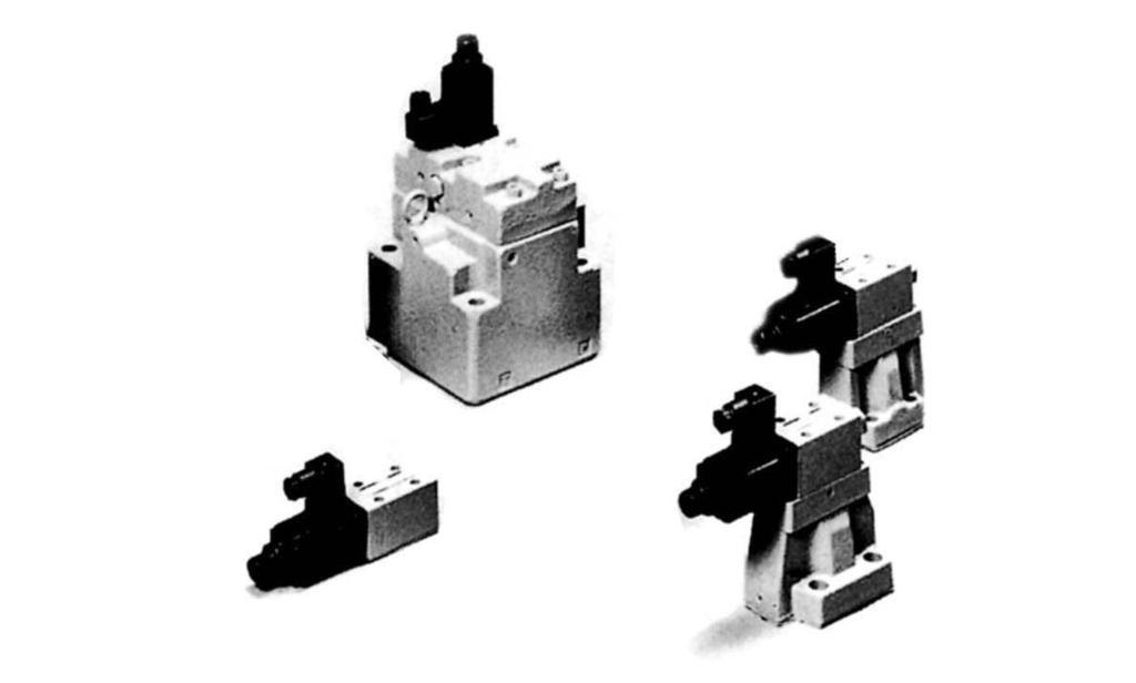
5 E-SERIES Hydraulic Pilot Relief Valves This valve consists of a DC solenoid and a direct-acting relief valve. It serves as a pilot valve for a low flow rate hydraulic system or a proportional electro-hydraulic control valve and controls the pressure in proportional to the input current. Note that this valve is used in conjunction with the applicable power amplifier. Ratings Description Model Numbers EDG P T -51 Max. Operating Pres. 24.5{250} Max. Flow L/min 2 Min. Flow L/min 0.3 Adj. Range Refer to Model Number Designation B : 800 Rated Current ma C : 900 H : 950 Coil Resistance Ω 10 Hysteresis 3% or less Repeatability 1% Approx. Mass kg 2 Model Number Designation ED G -01 V -C -1 -PN T13-51 Adj. Series Type of Valve Size Applicable Control Range Safety Valve Number Mounting { kgf/cm 2 } ED : B : 0.5~ 6.9 : General use { 5~ 70} None: Proportional G : C : 1.0~ 15.7 Without Safety Valve ElectroHydra Sub-Plate 01 V : Vent Control of { 10~ 160} Relief ulic Pilot Mounting Valve 1 H : 1.2~ : With Safety Valve Relief Valve { 12~ 250} (Omit if not required) 1. When the valve is to be used for vent control purpose, orifice adjustment is required due to piping capacity limitations. Therefore, consult your SEWON representative in advance. 2. Standard of T-line Orifice. Pres. Adj. Range B : T15, C : T13, H : T11 The orifice used as the pilot valve may differ from the standard orifice. Sub-Plate T-Line P-Line Orifice Orifice 2 PN: T15 Without Orifice T13 (Standard) T11 KS Graphic Symbols Design Number 51 Hydraulic Pilot Relief Valves Sub-plate Model Numbers Thread Size Rc Approx. Mass kg DSGM DSGM-01X-30 ¼ 0.8 DSGM-01Y-30 ⅛ ⅜ Without Safety Valve Please order the sub-plate using above the model number when you see it. The mounting surface should be used roughly 6-S after grind when you made it yourself. Sub-plate are shared with those for DSG-01 series solenoid operated valve. Please refer to page E-18 for dimension. With Safety Valve Hydraulic Pilot Relief Valves H-5
6 Appilcable Power Amplifiers For stable performance, it is rrecommended that SEWON's applicable power amplifiers be used (for details see page E-22). Attachment Mounting Bolts soket head cap screw : M5 45L 4 Pcs Model Number : AMN-D-10 (For DC power supply) Instructions Tank-Line Back Check that the tank line back pressure does not exceed 0.2 {2.0kgf/cm 2 } Vent Control When the valve is used for vent control of relief valves or for other valve vent control purposes, use the pipes of Dia. 6 mm, 300mm or less length for piping connection. If the pressure is instable, provide a 1.0 to 1.5 mm diameter orifice to the vent port of the relief valves or others. Circuit Control When the pressure in a circuit is directly controlled with this valve, set the trapped oil volume being more than 40cm 3. Low s The preselected pressure may become instable. To avoid such pressure instability, the flow rate should not be lower than 0.3 L/min. Safety Valve Setting The pressure of the safety valve at the maximum flow is preset at the value equal to the upper limit of the pressure adjustment range plus 2.{2.0kgf/cm 2 } In case where the upper limit of operating pressure is low or the upper limit of flow rate to be used is different from the specified maximum flow, please adjustand determine the setting pressure of the safety valve at the value calculated from the following formula. Setting pressure = (Operating pressure upper limit) + (Additional pressure indicated below) To lower the setting pressure, turn the safety valve pressure adjustment screw anti-clockwise. After adjustment, be sure to tighten the lock nut. Additional With Safety Valve Without Safety Valve Fully Extended 216 Fully Extended Adj. Screw for Safety Valve 3Hex. Soc. 5.5 Dia. Through 9.5 Bore 4Places INC For other dimensions, refer to the without safety valve. Lock Nut 10 Hex. The direction can be altered to every 90 degree angles. Port "P" Tank Port "T" Connector The direction can be altered to every 90 degree angles. Cable Departure Cable Applicable Outside Dia. 8-10mm Conductor Area Not Exceeding 1.5mm 2 Air Vent 3 Hex. Soc. 3Places Manual Adj. Screw 3 Hex. Soc. INC Mounting Surface (O-Ring Furnished) Note: For valve mounting surface dimensions, see the dimensional drawings of sub-plates (E-18) in common use. H-6 Hydraulic Pilot Relief Valves
7 E-SERIES Step Response(Example) These characteristics have been obtained by measuring on each valve. Therefore, they may vary according to a hydraulic circuit to be used. : 2L/min Trapped Oil Volume : 40cm 3 Viscosity : 30mm 2 /s{cst} Time Step Signal Step Signal Step Signal Time Time Frequency Response Frequency Control vs. Input Current Phase(deg.) Gain Phase Gain Trapped Oil Volume Viscosity Min. Adjustment Min. Adjustment Viscosity vs. Viscosity Input Current Viscosity vs. Oil Hydraulic Pilot Relief Valves Temperature Viscosity Hydraulic Pilot Relief Valve H-7
8 List of Seals and Solenoid Ass y Without Safety Valve EDG P T -51! CAUTION When making replacement of seals, please do it carefully after reading through the relevant instructions in the Operator's Manual. With Safety Valve EDG P T List of Seals Item Name of Parts Part Numbers Qty. 14 O-Ring JIS B A-P O-Ring JIS B B-P O-Ring JIS B B-P O-Ring JIS B B-P O-Ring JIS B B-P O-Ring AS (NBR, Hs90) 1 20 O-Ring JIS B B-P Fastener Seal SG-FCF-4 1 Note) O-Ring(Item 16, 18, 20) and the fastener seal(item 21) are Pilot Valve This table shows the proportional electro-hydraulic control valve which uses this valve(edg-01 ) for the pilot valve, the valve model number, and the solenoid assembly number. included in the solenoid assmbly. Valve Model Numbers Pilot Valve Model Numbers EBG-03-C-51 EDG-01V-C-1-PNT09-51 Solenoid Ass y EBG-03-H-51 EDG-01V-H-1-PNT09-51 Model Numbers 13 Solenoid Ass y EBG-03-C-T-51 EDG-01V-C-PNT09-51 EDG P T -51 E318-Y06M EBG-03-H-T-51 EDG-01V-H-PNT09-51 EDG-01V- - -P T -51 E318-Y06M EBG-06-C-51 EDG-01V-C-1-PNT10-51 Note) The connector assembly GDM-211-B-11(Item 12) is not included in the solenoid assmbly. Ass y. EBG-06-H-51 EBG-06-C-T-51 EBG-06-H-T-51 EDG-01V-H-1-PNT10-51 EDG-01V-C-PNT10-51 EDG-01V-H-PNT10-51 H-8 Hydraulic Pilot Relief Valve
9 E-SERIES Interchangeability between Old and New Design Specifications and Characteristics The Specification are not changed except as Input Current vs. Characteristics. For details contact us. Mounting Inerchangeability There is an inerchangeability in the mounting dimensions, however, the outside shape and dimensions are changed as shown below due to pilot valve improvement and other modifications. Air Vent 3 Hex. Soc. Old : Design 50 New : Design 51 Manual Adj. Screw 3 Hex. Soc. Manual Adj. Screw 3 Hex. Soc. Adaptor 22 Hex. Solenoid Fully Extended Solenoid Air Vent 3 Hex. Soc. Fully Extended Places Fully Extended 216 Fully Extended The solenoid assembly current design comes in two types: 1 E design and 2 60 design. See the figure on the left for an external view of type. 1. See the figure on the right for type.2. Model Numbers Additional {kgf/cm 2 } EBG {20.4} (At Flow rate 50 L/min) EBG {35.7} (At Flow rate 100 L/min) In case where the upper limit of operating pressure is low or the upper limit of flow rate to be used is different from the specified maximum flow, please adjust and determine the setting pressure of the safety valve at the value calculated from the following formula. Hydraulic Pilot Relief Valves Setting pressure = (Operating pressure upper limit) +(Additional pressure indicated below) Hydraulic Pilot Relief Valve H-9

10 Hydraulic Relief Valves This valve is derived by combining a small, high-performance 1/8 proportional electro-hydraulic pilot relief valve with a specially developed low-noise relief valve. With this valve, it is possible to regulate the system pressure in proportion to the input current. Note that this valve is used in conjunction with the applicable power amplifier. Ratings Description Model Numbers EBG EBG Max. Operating { kgf/cm 2 } 24.5{250} 24.5{250} Max. Flow Min. Flow L/min L/min Adjustment Range { kgf/cm 2 } Refer to Model Number Designation Rated Current Coil Resistance Hysteresis ma Ω C:770 C:750 H:820 H: % or less 3% or less Repeatability 1% 1% Approx. Mass kg Model Number Designation EB G -03 -C -T -51 Type of Adj. Design Series Number Safety Valve Valve Size Mounting Range Standard KS Graphic Symbols EB : Proportional ElectroHydraulic Pilot Relief Valve G : Sub-Plate Mounting C : ~ 15.7 { ~ 160} H : ~ 24.5 { ~ 250} None : With Safety Valve T:Without Safety Valve 51(standard) 5107(Low pres. Control Type) 5183 (Ext.Drain Type) Note) Min, adjustment pressure shall be refered to the curves on page H-12 Without Safety Valve Sub-Plate Series Sub-plate Thread Size Approx. Numbers Model Numbers Rc(PT) Mass kg EBG-03 BGM ⅜ 2.4 BGM-03X-20 ½ 3.1 EBG-06 BGM ¾ 4.7 BGM-06X With Safety Valve 쪾 Please order the sub-plate using above the model number when you see it. 쪾 Sub-plates are those for pilot operated relief valves. For dimensions, see page C-9. The mounting surface should be used roughly 6-S after grind when you made it yourself. Attachment Applicable Power Amplifiers Mounting Bolts For stable performance, it is rrecommended that SEWON's applicable power amplifiers be used (for details see page E-22). Model Number : AMN-D-10 (For DC power supply) Model Numbers EBG-03 EBG-06 Soket Head Cap Screw M12 40L 4pcs M16 50L 4pcs H-10 Hydraulic Relief Valve
11 E-SERIES Instructions Low s A flow rate of 3 L/min or higher should be used to avoid preselected pressure instability. Safety Valve The pressure of the safety valve is preset at the value equal to the upper limit of the pressure adjustment range plus added pressure. Model Additional { kgf/cm 2 } Numbers EBG {20.4} (At Flow rate 50 L/min) EBG {35.7} (At Flow rate 100 L/min) In case where the upper limit of operating pressure is low or the upper limit of flow rate to be used is different from the specified maximum flow, please adjust and determine the Additional Additional setting pressure of the safety valve at the value calculated from the following formula. Setting pressure = (Operating pressure upper limit) +(Additional pressure indicated below) With Safety Valve Fully Extended 216 Lock Nut 10 Hex. Adj. Screw for Safety Valve 3 Hex. Soc. Without Safety Valve Mounting Surface EBG-03 : ISO 6264-AR-06-2-A EBG-06 : ISO 6264-AS-08-2-A "Q" Dia. Through "S" Dia. Spotface 4Places INC For other dimensions, refer to the without safety valve. Connector The direction can be altered to every 90 degree angles. The direction can be altered to every 90 degree angles. Cable Departure Cable Applicable Outside Dia. 8-10mm Conductor Area Not Exceeding 1.5mm 2 Manual Adj. Screw 3 Hex. Soc. INC Tank Port T Port P This port is not used. It is provided because of the common use of the body with the low-noise type pilot operated relief valve. One the sub-plate, plug the port which corresponds to this port. Hydraulic Relief Valves Air Vent 3 Hex. Soc. 3Places Mounting Surface (O-Ring Furnished) 6 Dia. Locating Pin Model Numbers A B C D E F H J K L N Q S U EBG EBG Note: For valve mounting surface dimensions, see the dimensional drawings of sub-plates C-9) in common use. Hydraulic Relief Valve H-11
12 Min. Adjustment Min. Adjustment Min. Adjustment Step Response(Example) These characteristics have been obtained by measuring on each valve. Therefore, they may vary according to a hydraulic circuit to be used. Trapped Oil Volume : 1L Viscosity : 30mm 2 /s{cst} Step Signal Step Signal Time Time Step Signal Step Signal Time Time H-12 Hydraulic Relief Valve
13 E-SERIES Input Current vs. Input Current Frequency Response Trapped Oil Volume : 1L Viscosity : 30 mm2 /s{cst} Frequency Viscosity vs. Oil Input Current Viscosity Phase(deg.) Phase(deg.) Gain Gain Pressue Pressue Frequency Phase Phase Gain Gain Temperature Viscosity Temperature Viscosity Hydraulic Pilot Relief Valves vs. Viscosity : 30 mm2 /s{cst} Phase(deg.) Phase(deg.) Hydraulic Relief Valve H-13
14 List of Seals and Pilot Valves! CAUTION When making replacement of seals, please do it carefully after reading through the relevant instructions in the Operator's Manual. Pilot Valve 10 Valve Model Numbers EBG-03-C-51 EBG-03-H-51 EBG-03-C-T-51 EBG-03-H-T-51 EBG-06-C Pilot Valve Model Numbers EDG-01V-C-1-PNT09-51 EDG-01V-H-1-PNT09-51 EDG-01V-C-PNT09-51 EDG-01V-H-PNT09-51 EDG-01V-C-1-PNT EBG-06-H-51 EBG-06-C-T-51 EBG-06-H-T-51 EDG-01V-H-1-PNT10-51 EDG-01V-C-PNT10-51 EDG-01V-H-PNT Note) For the details of pilot valves, refer to "Pilot Relief Valves" on page H List of Seals Part Numbers Item Name of Parts Qty. EBG-03 EBG O-Ring JIS B B-P32 JIS B B-P O-Ring JIS B B-P28 JIS B B-P O-Ring JIS B B-P9 JIS B B-P O-Ring JIS B B-P9 JIS B B-P9 2 NBR NBR 15 O-Ring AS AS Hs90 Hs90 16 O-Ring JIS B B-P18 JIS B B-P28 2 H-14 Hydraulic Relief Valve
15 E-SERIES Interchangeability between Old and New Design Specifications and Characteristics The Specification are not changed except as Input Current vs. Characteristics. For details contact us. Mounting Inerchangeability There is an inerchangeability in the mounting dimensions, however, the outside shape and dimensions are changed as shown below due to pilot valve improvement and other modifications. Old : Design 50 New : Design 51 Fully Extended A Fully Extended A Manual Adj. Screw 3 Dia Manual Adj. Screw 3 Dia. Air Vent 3 Hex. Soc. Pilot Valve Design Air Vent 3 Hex. Soc. 3 Places Pilot Valve Design Adaptor 22 Hex. Manual Adj. Screw 3 Dia See EDG-01(page H-9) for details of the Solenoid Ass y See EDG-01(page H-9) for details of the Solenoid Ass y M a n u a l Adj. Screw for Safety Valve 3 Hex. Soc. Model Numbers A B C D E (OLD) EBG (NEW) EBG (OLD) EBG (NEW) EBG Hydraulic Pilot Relief Valves Hydraulic Relief Valve H-15


16 10Ω-10Ω Series Hydraulic Flow Control and Relief Valves This flow control and relief valve is an energy-saving valve that supplies the minimum pressure and flow necessary for actuator drive. Since this valve controls the pump pressure by following the load pressure while keeping the differential pressure minimized, it serves as a low power consumption energy-saving, metre-in, controlled flow control valve. Further, since a temperature compensation function is incorporated, this valve provides consistent flow control without respect to the fluid temperature. Ratings Description Model Numbers EFBG EFBG Max. Operating 24.5 {250} 24.5 {250} Max. Flow L/min Metred Flow Adjustment Range L/min Min. Pilot 1~ ~ {15.3} 1.5 {15.3} Pilot Flow L/min at Normal at Transition Flow Controls Rated Current ma Coil Resistance Ω Differential { kgf/cm 2 } Hysteresis or less {7.1} 0.7 {7.1} 3% or less 3% or less KS Graphic Symbols Whth Proportional Pilot Relief Valve External Pilot Internal Pilot Repeatability 1% 1% C : 1.4~15.7 C : 1.4~15.7 Controls 1 Pres. Adj. Range Rate Current Coil Resistance 2 { kgf/cm 2 } ma Ω {14~160} {14~160} H : 1.4~24.5 H : 1.4~24.5 {14~250} {14~250} C : 890 C : 880 H : 970 H : Hysteresis 3% or less 3% or less Repeatability 1% 1% Approx. Mas kg Refer to page H-18~H-19 1.The specifications for pressure controls are applied to models with proportional pilot Whthout Proportional Pilot Relief Valve External Pilot Internal Pilot relief valve.(ex:efbg c- -51) 2.The maximum pressure adjustment range of the models without proportional pilot relief valves is 24.5.(Ex:EFBG ) H-16 10Ω-10ΩSeries Flow Control and Relief Valve
17 E-SERIES Model Number Designation EFB G C -E -51 Series Number Type of Mounting Valve Size Max. Metred Flow L/min Proportional Pilot Relief Valve Adjustment Range Pilot Connection Design Number EFB : Hydraulic Flow G : Subplate C, H : See Specifications None : Internal Pilot 51(standard) 5103 (160L/min) Control and Relief Valve Mounting E : External Pilot 5118 (standard) Attachment Mounting Bolts Model Numbers soket head cap screw Appilcable Power Amplifiers For stable performance, it is rrecommended that SEWON's applicable power amplifiers be used (for details see page H-22). EFBG-03 EFBG-06 M10 65L 4pcs M16 100L 4pcs Valve Model Numbers Power Amplifier Model Number For Flow Control For Pres. Control EFBG (E)-51 C EFBG (E)-5118 H AMN-D-10 AMN-D-10 Sub-plate Valve Model Sub-plate Model Thread Size Approx. Instructions Drain Back Numbers Numbers RC(PT) Mass kg Check that the drain back pressure does not exceed 0.2. EFBG-03 EFBGM-03Y-20 ¾ 6 EFBGM-03Z When Relief Valve Passing is Low in Control State EFBGM-06X EFBG-06 EFBGM-06Y-20 1¼ 16 Sub-plates are available. Specify the sub-plate model number from the table above. When sub-plates are not used, the mounting surface should have a good machined finish. To avoid preselected pressure instability, use a passing flow rate of 15 L/min or higher. Further, check that the tank-line back pressure dose not exceed 0.5.{5.1kgf/cm 2 } Safety Valve Setting The pressure of the saffety valve is preset at the value equal to the upper limit of the pressure adjustment renge plus 2. Please adjust the pressure of the valve so preset to meet the pressure to be used actually. To lower the pressure setting, turn the safety valve pressure adjustment screw anti-clockwise. After adjustment, be sure to tighten the lock nut. 10Ω-10ΩSeries Flow Control and Relief Valve 10Ω-10ΩSeries Flow Control and Relief Valve H-17
18 EFBG C- -51 Adj. Screw for Safety Valve 3 Hex. Soc. Lock Nut 10 Hex Dia. Through 17.5 Dia. Spotface 4 Places Tank Port T Vent Port V Inlet Port P Outlet Port A Connector Cable Departure Cable Applicable Outside Dia. 8~10mm Sub-Plate Connector Cable Departure Cable Applicable Outside Dia. 8~10mm M10 Thd. 18 Deep 4 Places 11 Dia. Through 17.5 Dia. Spotface 4 Places 29 Dia. 3 Places 17.5 Dia. 10 Deep 2 Places Dia. Rc 1/4 (PT1/4) (From Rear) 14 Dia. Rc1/4 (PT1/4) (From Rear) Rc "B" (PT "B") 6 Dia. Rc1/4 Thd. (RT1/4) (From Rear) Two Locating Pins 6 Dia. Mounting Surface (O-Rings Funished) Mass 16Kg Sub-plate Model Number EFBGM-03Y-20 B ¾ EFBGM-03Z-20 1 H-18 10Ω-10ΩSeries Flow Control and Relief Valve
19 E-SERIES EFBG C-51 Adj.Screw for Safety Valve 3 Hex. Soc. Lock Nut 10 Hex 17.5 Dia. Through 26 Dia. Spotface 4 Places Tank Port T 85.7 Vent Port V 35.7 Inlet Port P Fully Extended EFBG-06-C/H-- 조합 Sub-Plate Cable Departure Connector Cable Applicable Outside Dia.8~10mm Cable Departure Cable Applicable Outside Dia.8~10mm Drain Port Y Outlet Port A Pilot Port X Connector M16 Thd. 30 Deep 4 Places 17.5 Dia. Through 26 Dia. Spotface 4 Places Rc1/4 (PT1/4) (From Rear) 6.2 Dia. 14 Dia. Rc3/8 (PT3/8) (From Rear) 29 Dia. 3 Places 17.5 Dia. 10 Deep 2 Places Rc "J" (PT "J") 6.2 Dia. Rc1/4 Thd. (RT1/4) (From Rear) Two Locating Pins 16 Dia. 171 Mounting Surface (O-Rings Funished) Mass 23Kg Ω-10ΩSeries Flow Control and Relief Valve Sub-Plate Medel Numbers B D E F H J EFBGM-06X EFBGM-06Y ¼ 10Ω-10ΩSeries Flow Control and Relief Valve H-19
20 Step Response (Flow Controls) These characteristics have been obtained by measuring on each valve. Therefore, they may vary according to a hydraulic circuit to be used. Step Signal Step Signal Step Response ( Controls) Time Time These characteristics have been obtained by measuring on each valve. Therefore, they may vary according to a hydraulic circuit to be used. Step Signal Step Signal Time Time Trapped Oil Volume Trapped Oil Volume Input Current vs. Flow Input Current Input Current Input Current vs. Input Current Input Current H-20 10Ω-10ΩSeries Flow Control and Relief Valve
21 E-SERIES List of Seals, Pilot Valves, Solenoid Ass y! CAUTION When making replacement of seals, please do it carefully after reading through the relevant instructions in the Operator's Manual List of Seals R-R Part Numbers Item Name of Parts EFBG-03 Qty. EFBG-06 Qty. 38 O-Ring JIS B B-P9 5 JIS B B-P O-Ring AS (NBR, Hs70) 1 JIS B A-P O-Ring JIS B B-P28 6 JIS B B-P O-Ring JIS B B-G30 1 JIS B B-P O-Ring JIS B B-P O-Ring JIS B A-P Ω-10ΩSeries Flow Control and Relief Valve 44 O-Ring JIS B A-P O-Ring JIS B B-P32 1 JIS B B-P O-Ring JIS B B-P28 1 JIS B B-P44 1 Solenoid Ass y Valve Model Numbers 23 Solenoid Ass y Model Numbers 20 Solenoid Ass y Model Numbers EFBG- - -C-(E) EFBG- - -H-(E) E318-Y06M E318-Y06M Note) 1. For the details of seals for solenoid Ass y see page H The connector assembly GDM-211-B-11(Item 21) is not included in the solenoid assembly. 10Ω-10ΩSeries Flow Control and Relief Valve H-21
22 Power Amplifiers For Hydraulic Control Valves These are power amplifiers to be used exclusively to operate the electro-hydraulic proportional valves. Various type and models on available for a variety applications. Type Model Number Applicable to Control Valve Function An amplifier which is operated by a battery power supply(24 V). By giving the command of DC voltage to the amplifier, current in proportion to that voltage will flow in the solenoid DC Input For DC Power or Flow Control of the control valve in order to control pressure or flow rate. An external setting unit which makes the command voltage and a DC power supply(or a function generator) are 24 V DC AMN-D-10 (For 10ΩSol.) necessary, but if a variable resistor for external setting is only one, the internal power supply for amplifier can be used. Variable Resistor amplifier Valve Instructions The power amplifiers should be kept away from hot and humid conditions which may deteriorate some components of the power amplifiers. They also should be installed in the clean and dry place where the vibration is minmal. Please avoid to install the power ampllfiers in the complete enclosure or get them enclosed totally as they need to radiate the heat from semiconductors or ICs inside. Please use shielded wires for input signal transmission to prevent the amplifiers from any interference such as noise from outside. H-22 Power Amplifiers

23 E-SERIES Compact Power Amplifiers For 10ΩSeries Control Valve Power Amplifiers For 10Ω Series Control Valves Compact Power Amplifiers For 10Ω proportional solenoids. The power supply is 24 V DC. It uses a new circuitry to be slow to heat. Ratings Description Model No. AMN-D-10 Model Number Designation AMN -D -10 Type of Function DC Input Type Series Number Type of Function Design Number Max. Output Current 1A(10Ω Solenoid) AMN D : DC Input Type 10 Power Input(Max.) Input Impedance Max. Gain Dither Temperature Drift(Max.) Power Supply DC+10V 10 kω 1A/5V Vairable 0.2mA/ DC24V(DC20~30V) Applicable to Valve Name of Valve Pilot Relief Valves Relief Valves 10Ω-10Ω Series Model Numbers EDG-01 EBG-03 EBG-06 Max. Input Power Ambient Temperature External Setting Resistance 25W 0 ~50 C 1kΩ High Flow Series Flow Control and Relief Valves EFBG-03 EFBG-06 Approc. Mass 0.2 kg 4Dia. Through 2 Places SEWON Setting Adjuster [Example Diagram] Power Amplifiers Zero Adjuster Span Adjuster Detail of Terminal Board Power Terminal Number Name Terminal Board (Refer to table on the right) Indicator Lamp 1 Power Supply +24V 2 Power Supply 0V 3 Ground G 4 Internal Power Supply +12V 5 Input Signal IN 6 Input Signal COM 7 8 Out to Valve Solenoid SOL Power Amplifiers H-23
PROPORTIONAL ELECTRO-HYDRAULIC CONTROLS
 H PROPORTIONAL ELECTRO-HYDRAULIC CONTROLS Hydraulic Controls H-3 H-1 E Series Hydraulic Controls Hydraulic Controls Max. Maximum Flow Types KS Graphic Symbols Operating L/min 1 2 3 5 10 20 30 50 100 200
Series Proportional Electro-Hydraulic Controls
 Proportional Electro-ydraulic Controls Types Graphic Symbols Max. Operating Pressure () Maximum Flow U.S.GPM. 3 3 3 L/min Page Pilot Relief Valves. (3) EDG 67 Relief Valves. (3) EBG 3 6 676 Relieving and
Proportional Electro-Hydraulic Pilot Relief Valves
 Proportional Electro-Hydraulic This valve consists of a small DC solenoid and a direct-acting relief valve. It serves as a pilot valve for a low flow rate hydraulic system or a proportional electro-hydraulic
EH SERIES PROPORTIONAL ELECTRO-HYDRAULIC CONTROL VALVES
 Pub. EC- E SERIES ELECTRO-YDRAULIC CONTROL VALVES Pilot Relief / Relief / Reducing and Relieving / Flow Control / Flow Control and Relief / Directional and Flow Control Up to. ( PSI), L/min (6 U.S.GPM)
E SERIES. Proportional Electro-Hydraulic Relief Valves. Specification. Model Number Designation. Attachment Mounting Bolts
 ydraulic Relief s The electro hydraulic relief valve is designed for compactness and high efficiency. The valve provides fast proportional response to the input current. For linear pressure control a special
PROPORTIONAL ELECTRO-HYDRAULIC CONTOROLS
 H PROPORTIONAL ELECTRO-HYDRAULIC CONTOROLS -Hybrid Components...Page Proportional Electro-Hydraulic Control Valves...Page 7 Proportional Electro-Hydraulic Controls High-accuracy, simple, convenient realizes
Proportional Electro-Hydraulic Flow Control and Relief Valves
 Ω Ω Proportional Electro-ydraulic Flow ontrol and Relief Valves This flow control and relief valve is an energy-saving valve that supplies the minimum pressure and flow necessary for actuator drive. Since
Hydraulic Fluids. Note: For use with hydraulic fluids other than those listed above, please consult your Yuken representatives in advance.
 Hydraulic Fluids Fluid Types Any type of hydraulic fluids listed in the table below can be used. Petroleum base oils Use fluids equivalent to ISO VG 32 or VG 46. Use phosphate ester or polyol ester fluid.
EHBG-03 EHBG-06 EHBG-10. Refer to Model No. Designation. 2% or Less(1%) 1% or Less *2. Refer to frequency Response on page V DC
 1% or Less *2. Refer to frequency Response on page V DC") Proportional Electro-ydraulic These valves, consist of a small size but high performance E series electro-hydraulic proportional pilot relief valve and a low noise type relief valve. The valves control
Proportional Electro-ydraulic These valves, consist of a small size but high performance E series electro-hydraulic proportional pilot relief valve and a low noise type relief valve. The valves control
Proportional Electro-Hydraulic Flow Control (and Check) Valves
 Valves") Proportional Electro-Hydraulic Flow Control (and Check) Valves EH SERIES The system flow rate can be controlled remotely as desired by regulating input voltage. Further, since pressure and temperature
Proportional Electro-Hydraulic Flow Control (and Check) Valves EH SERIES The system flow rate can be controlled remotely as desired by regulating input voltage. Further, since pressure and temperature
Proportional Electro-Hydraulic Relieving and Reducing Valves
 These valves consist of a small size but high performance EH series electro-hydraulic proportional pilot relief valve and reducing valve with relief function. The valves control the system pressure proportionally
Proportional Electro-Hydraulic Directional and Flow Control Valves
 Proportional Electro-Hydraulic s These valves are double-deck directional and flow control valves employing as their pilot the electro-hydraulic proportional pressure reducing valves with two proportional
Proportional Electro-Hydraulic Flow Control (and Check) Valves
 Valves") Ω Proportional Electro-ydraulic Flow Control (and Check) Valves Since the preselected flow rate continuously varies in proportion to the current input to the valve, the system flow rate can be remotecontrolled
Ω Proportional Electro-ydraulic Flow Control (and Check) Valves Since the preselected flow rate continuously varies in proportion to the current input to the valve, the system flow rate can be remotecontrolled
E SERIES. Proportional Electro-Hydraulic Relief Valves. Specification. Model Number Designation. Attachment Mounting Bolts
 s The electro hydraulic relief valve is designed for compactness and high efficiency. The valve provides fast proportional response to the input current. For linear pressure control a special venting feature
Direct Operated Type Directional and Flow Control Valves
 Specifications igh Response Type Proportional Electro-ydraulic Directional and Flow Control Valves igh response, high precision and high reliability are achieved be a combination of a compact and powerful
UNLOADING RELIEF VALVES
 UNLOADING RELIEF VALVES BUG-6/1 (3/4, 1-1/4) Specifications / Model Number Designation Up to 21 (35 ), L /min (66 ) Pub. E- These valves are used to operate the pumps with minimum load in accumulator circuits
PRESSURE REDUCING AND RELIEVING VALVES
 REDUING AND RELIEVING VALVES RBG-3 / 6 (3/8, 3/4) Mounting Specifications / Model Number Designation / Others Up to 25 (363 ), 25 (33 U.S.GPM) reducing and relieving valves are composite pressure control
PRESSURE REDUCING AND RELIEVING VALVES
 REDUING AND RELIEVING VALVES RBG-3 / 6 (3/8, 3/4) Mounting Specifications / Model Number Designation / Others Up to 5 (363 ), (33 U.S.GPM) reducing and relieving valves are composite pressure control valves
A Series Variable Displacement Piston Pumps
 A Series Variable Displacement Piston Pumps A37 A56 A1637 A16 A10 A Series Variable Displacement Piston Pumps Pump Type Graphic Symbol Geometric Displacement cm 3 /rev 1 5 10 0 50 100 00 300 Maximum Operating
FLOW CONTROLS. Maximum Flow U.S.GPM Maximum Operating Pressure MPa (PSI) Graphic Symbols. Page. Valve Type.
 Graphic Symbols. Page. Valve Type.") FLOW CONTROLS Valve Type Graphic Symbols Maximum Operating Pressure MPa (PSI) Maximum Flow U.S.GPM 5 5 5 5 5 5 5 Page Flow Control Valves (5) 77 Flow Control and Check Valves (5) 77 Pilot Operated Flow
FLOW CONTROLS Valve Type Graphic Symbols Maximum Operating Pressure MPa (PSI) Maximum Flow U.S.GPM 5 5 5 5 5 5 5 Page Flow Control Valves (5) 77 Flow Control and Check Valves (5) 77 Pilot Operated Flow
Note: For use with hydraulic fluids other than those listed above, please consult Yuken representative in advance.
 PRESSURE CONTROLS Fluid Types Any type of hydraulic fluids listed in the table below can be used Petroleum base oil Synthetic Fluids Water Containing Fluids Use equivalent to ISO VG32 or VG46. Use phosphate
Proportional Valve.
 Proportional Valve Electro-Hydraulic Proportional Pilot Relief Valve Electro-Hydraulic Proportional Flow & Directional Control Valve Electro-Hydraulic Proportional Relief & Flow Control Valve Electronic
AR Series Variable Displacement Piston Pumps. AR Series Variable Displacement Piston Pumps. AR Series Variable Displacement Piston Pumps
 Variable Displacement Piston Pumps AR Series Variable Displacement Piston Pumps Geometric Displacement Maximum cm 3 /rev Operating Pump Type Graphic Symbol Pressure Page 1 2 5 10 20 50 100 150 MPa Variable
High Pressure, High Flow Rate Modular Valves
 High Pressure, High Modular Valves EIC-F-14- MODULR VLVES The modular valves are functional elements with which a hydraulic system can be composed and built easily by stacking them with the mounting bolts.
SHUT-OFF TYPE SOLENOID OPERATED DIRECTIONAL VALVES DSPC/DSPG-01/03(1/8,
 SHUT-OFF TYP SOLNOID OPRATD VALVS DSPC/DSPG-/(/8, /8) Cartridge Type / Mounting Up to 5 MPa (6 PSI), 8 (. U.S.GPM) Pub. C- The shut-off type solenoid operated directional valves are poppet type solenoid
Pressure Reducing and Relieving Valves
 reducing and relieving valves are composite pressure control valves having pressure reducing and counterbalancing functions developed for hydraulic balancing circuits. Specifications RBG-- * - * RBG-6-
A Series Variable Displacement Piston Pumps. A16 Type performance characteristics A16 Type Noise level characteristics.
 EIC--12- PISTON PUMPS Series Variable Features High efficiency Under the conditions of pressure 16 Kgf/cm² and speed 18 r/min. volumetric efficiency is over 98% and the overall efficiency is over 9%. Low
06 SERIES MODULAR VALVES. Pub. EC-1404
 6 SERIES General Information Mounting Surface : ISO -AE-8--A, CETOP-8, NPA-D6 Up to 5 MPa (363 PSI), 5 L /m in (3 U.S.GPM) Pub. EC- The modular valves are functional elements with which a hydraulic system
AR Series Variable Displacement Piston Pumps. [Comparison of AR16 with A16 ] A16,32 Design 188. AR16,22 Design 130. Ratio of Mass (AR16/A16) 74%
![AR Series Variable Displacement Piston Pumps. [Comparison of AR16 with A16 ] A16,32 Design 188. AR16,22 Design 130. Ratio of Mass (AR16/A16) 74%](/thumbs/89/97534102.jpg "AR Series Variable Displacement Piston Pumps. [Comparison of AR16 with A16 ] A16,32 Design 188. AR16,22 Design 130. Ratio of Mass (AR16/A16) 74%") PISTON PUMPS EIC--11- Features Smaller in Size and Lighter in Mass s indicated in the dimensional comparison presented below, the R1 is smaller than the 1(3 design). lso, the mass of R1 is substantially
PISTON PUMPS EIC--11- Features Smaller in Size and Lighter in Mass s indicated in the dimensional comparison presented below, the R1 is smaller than the 1(3 design). lso, the mass of R1 is substantially
" " Series Variable Displacement Piston Pumps
 " " Series Variable Displacement Piston Pumps Compensator Type Constant Power (Torque) Control Type Load Sensing Type Pump Type Graphic Symbol Geometric Displacement cu. in./rev...5 5 5 5 5 cm /rev Maximum
" " Series Variable Displacement Piston Pumps
 " " Series Variable Displacement Piston Pumps AR Axial Port Type AR Side Port Type "AR" series variable displacement pump has been developed which the aim of even further the quientness in operation, smaller
"AR" SERIES PISTON PUMPS. Variable Displacement-Single Pumps Pressure Compensator Type,AR16 / AR22-FR01
 "AR" SERIES Variable Displacement-Single Pumps Compensator Type, / AR-FR1 Up to 1 MPa ( PSI),. cm /rev ( CU.IN./rev) Pub. EC- A Compensator Valve Adj. Screw Spool Control Piston Drain Port Flow Adj. Screw
Min. Metered Flow Capacity L/min. Max. Oper. Pressure Kgf/cm (0.04)* F- FC G N -11 H01. Max. Metered Flow Capacity L/min.
* F- FC G N -11 H01. Max. Metered Flow Capacity L/min.") Flow Control These are pressure and temperature compensating type valves and maintain a constant flow rate independent of change in system pressure (load) and temperature (Viscosity of the fluid). They
Flow Control These are pressure and temperature compensating type valves and maintain a constant flow rate independent of change in system pressure (load) and temperature (Viscosity of the fluid). They
"AR" SERIES PISTON PUMPS. Variable Displacement-Single Pumps Pressure Compensator Type,AR16 / AR22- FR01 3
 "AR" SERIES Variable Displacement-Single Pumps Compensator Type,AR / AR- FR Up to MPa ( PSI),. cm /rev (.5 CU.IN./rev) Pub. EC- A Compensator Valve Adj. Screw Spool Control Piston Drain Port Flow Adj.
"A" Series Variable Displacement Piston Pumps Single Pump, Pressure Compensator Type
 A"A" Series PISTON PUMPS Single Pump, Compensator Graphic Symbol M O Specifications Model s A-FRB- A-FRC/H- A- -R-- - -K- A- -R-- - -K- A- -R-- - -K- A- -R-- - -K- A- R S- A9- R S- A- R S- Geometric Displacement
PISTON PUMPS. A3H Series High Pressure Variable Displacement Piston Pumps. Features. A3H Series Variable Displacement Piston Pumps.
 3H Series High Variable EIC--13- Features 1 Control System for Wide Range pplication: 1 Compensator Type 3H Series High Variable 9 Constant Power Control Type 1 Load Sensing Type For these controls system,
03 SERIES. General Information Mounting Surface : ISO 4401-AC-05-4-A, CETOP-5, NFPA-DO2 Up to 25 MPa (3630 PSI), 70 L /min (18.5 U.S.
, 70 L /min (18.5 U.S.") 3 SERIES General Information Mounting Surface : ISO 44-C--4-, CETO-, N-DO Up to Ma (363 SI), 7 L /min (8. U.S.GM) ub. EC-43 MODULR VLVES The modular valves are functional elements with which a hydraulic
3 SERIES General Information Mounting Surface : ISO 44-C--4-, CETO-, N-DO Up to Ma (363 SI), 7 L /min (8. U.S.GM) ub. EC-43 MODULR VLVES The modular valves are functional elements with which a hydraulic
Pilot Operated Flow Control Valves / Pilot Operated Flow Control and Check Valves
 FLOW CONTROLS Flow control of these valves is continuously made by a hydraulically operated pilot piston mechanism which controls opening area of the orifice of the valve. With the use of these valves,
High Response Type Proportional Electro-Hydraulic Directional and Flow Control Valves
 igh Response ype roportional Electro-ydraulic s igh response, high precision and high reliability are achieved by a combination of compact and powerful solenoid and spool-position-detection LVD. Direct
PROPORTIONAL VALVES SERVO VALVES. Maximum operating pressure MPa {kgf/cm 2 } Model [Model No.]
![PROPORTIONAL VALVES SERVO VALVES. Maximum operating pressure MPa {kgf/cm 2 } Model [Model No.]](/thumbs/82/85298236.jpg "PROPORTIONAL VALVES SERVO VALVES. Maximum operating pressure MPa {kgf/cm 2 } Model [Model No.]") J PROPORTIONAL VALVES SERVO VALVES J Model [Model No.] Solenoid pilot operated proportional relief valve [JRP] Solenoid operated proportional relief valve [JRPL] Type C2 solenoid operated proportional
J PROPORTIONAL VALVES SERVO VALVES J Model [Model No.] Solenoid pilot operated proportional relief valve [JRP] Solenoid operated proportional relief valve [JRPL] Type C2 solenoid operated proportional
"G" SERIES SHOCKLESS TYPE SOLENOID OPERATED DIRECTIONAL VALVES G-DSG-01/03 (1/8, 3/8) "G" SERIES SHOCKLESS TYPE
 G SERIES SHOCKLESS TYPE") "G" SRIS SHOCKLSS Y NOID ORD DIRCIL VLVS G-DSG-1/3 (1/, 3/) "G" SRIS SHOCKLSS Y NOID CROLLD ILO ORD DIRCIL VLVS G-DSHG-/ (1/, 3/) Mounting Up to 5 Ma (33 SI), 5 L /m in (.1 U.S.GM) ub. C-5 DIRCIL CROLS
"G" SRIS SHOCKLSS Y NOID ORD DIRCIL VLVS G-DSG-1/3 (1/, 3/) "G" SRIS SHOCKLSS Y NOID CROLLD ILO ORD DIRCIL VLVS G-DSHG-/ (1/, 3/) Mounting Up to 5 Ma (33 SI), 5 L /m in (.1 U.S.GM) ub. C-5 DIRCIL CROLS
OBE (On-Board Electronics) Type Direct Operated Linear Servo Valves (Size: 01 & 03) LSVG-01-EH-*-**-**-10, LSVG-03EH-*-**-**-10/1006
 Type Direct Operated Linear Servo Valves (Size: 01 & 03) LSVG-01-EH-*-**-**-10, LSVG-03EH-*-**-**-10/1006") NO. 10 01E September 1, 2010 Public Relations Group Products Publicity Section Sales Administration Department Hamamatsucho Seiwa Bdg., 4-8, Shibadaimon 1-chome, Minato-ku, Tokyo 105-0012, Japan Tel: +81-3-3432-2113
NO. 10 01E September 1, 2010 Public Relations Group Products Publicity Section Sales Administration Department Hamamatsucho Seiwa Bdg., 4-8, Shibadaimon 1-chome, Minato-ku, Tokyo 105-0012, Japan Tel: +81-3-3432-2113
10 SERIES MODULAR VALVES. Pub. EC-1405
 SERIES General Information Mounting Surface : ISO ----, CETOP-, NP-D Up to 5 MPa (363 PSI), 8 L /m in ( U.S.GPM) Pub. EC-5 The modular valves are functional elements with which a hydraulic system can be
Modular Valves. Ratings
 High Pressure, High Flow Rate Features Installation and mounting space can be minimized. No special skill is required for assembly and any addition or alternation of the hydraulic circuit can be made quickly
Solenoid Pilot Operated Proportional Directional Control Valve
 Solenoid Pilot Operated Proportional Directional Control Valve Features hese solenoid pilot operated proportional directional control valves use a nozzle flapper valve as pilot valve and perform spool
High Pressure, High Flow Rate Modular Valves
 eatures Installation and mounting space can be minimized. No special skill is required for assembly and any addition or alternation of the hydraulic circuit can be made quickly and easily. roblems such
RELIEF VALVES Remote Control / Direct Type Pilot Operated / Solenoid Controlled
 RELIEF VALVES Remote ontrol / Direct ype ilot Operated / Solenoid ontrolled Up to 5 Ma (3630 SI), 0 L /m in (06 U.S.GM) ub. E-00 Remote ontrol Relief Valves... age 3 his valve is used as a remote control
Vent Connection. Pres. Adj. Range BT BG * ~ BG F- B T -03 P -V -32.
 These valves protect the hydraulic system from excessive pressure, and can e used to maintain constant pressure in a hydraulic system. Remote control and unloading are permitted y vent circuit. PRESSURE
Max. Operating Pressure Kgf/cm 2
 In-Line Check Valves DIRCTIONAL CONTROLS These valves allow free flow in one direction and prevent flow in the reverse direction. Cracking pressure specified is the pressure required to open the valve
10 SERIES MODULAR VALVES
 General Information Mounting Surface : ISO 441-A-1-4-A, CETOP-1, NPA-D1 Up to 5 MPa (363 PSI), 8 L /min (11 U.S.GPM) Pub. EC-145 The modular valves are functional elements with which a hydraulic system
EMulti Purpose Control Valves
 IRCTIONAL CONTROLS The Yuken Multi-Purpose Valves Comply with The Needs of Reducing Cost and Size of Your Machine YUKN's Multi Purpose Valve s are compound valves composed of the main valve having four
ARL1 Series Piston Pumps. ARL1 Series Piston Pumps. Geometric Displacement. Maximum cm 3 /rev
 ARL1 Series Piston Pumps Geometric Displacement Maximum cm 3 /rev Operating Pump Type Graphic Symbol Pressure Page 1 2 5 10 20 50 100 150 MPa ARL1-6 Piston Pump ARL1-8 ARL1-12 7 8 ARL1-16 5 Hydraulic Fluids
Series Variable Displacement Piston Pump
 AH Series Variable Displacement Piston Pump AH AH7 AH AH45 KS Geometric Displacement Max. Operating Series Graphic cm 3 /rev Pres. Page Symbol 3 4 5 6 7 8 9 3 4 5 MPa {kgf/cm 2 } AH-F-R--K-S- AH AH45-F-R--K-S-
Publ. 3-EN 2950-A. DENISON HYDRAULICS Pressure Relief Valve R6V
 Publ. 3-EN 2950-A DENISON HYDRAULICS Pressure Relief Valve R6V FEATURES, SYMBOL FEATURES High Performance: R6V valves are designed for a maximum pressure of 350 bar and a flow capacity up to 650 l/min.
Restrictors / One Way Restrictors
 FLOW CONTROLS This valve is used to regulate an actuator speed in a circuit where line pressure is almost steady and small fluctuation of oil flow due to pressure changes is permitted. Integrated check
Solenoid Controlled Relief Valves
 hese valves are a comination of a pilot operated relief valve and a solenoid operated directional valve. Piping etween the two is eliminated as the solenoid valve is directly mounted on the relief valve
Max. Reversed Free Flow L/min
 These Valves are the combination of flow control valve, a deceleration valve and a check valve and used mainly for controlling rapid traverse and feed cycle in machine tools. Switching from rapid traverse
50T,150T,250F SERIES Fixed Displacement-Single, Double, Combination
 T,T,F SERIES Fixed Displacement-Single, Double, Combination Up to 7 MPa ( PSI), 9 cm /rev (. CU.IN./rev) Single Pumps These pumps are widely used as a source of hydraulic power. They combine stable performance
MODULES. Maximum Flow U.S.GPM. Max. Operating Pressure MPa (PSI) L/min. 005 Series 25 (3630) Modular Valves. 01 Series 31.
 L/min. 005 Series 25 (3630) Modular Valves. 01 Series 31.") F MODULES YUKEN's are stack type valves, and require no piping. They not only rationalise system build, but they also meet the technical requirements for a variety of hydraulic systems. Stacking systems
F MODULES YUKEN's are stack type valves, and require no piping. They not only rationalise system build, but they also meet the technical requirements for a variety of hydraulic systems. Stacking systems
"A" Series Piston Pumps Variable Displacement-Single Pumps Electro-Hydraulic Proportional Pressure & Flow Control. Type
 Variable Displacement-Single Pumps Electro-Hydraulic Proportional & Flow Type 6 / / 7 / 6 / 7 / 9 / Model Number Designation Safety valve Input Signal for Flow Input Signal for mplifier Proportional Solenoid
Variable Displacement Piston Pumps
 A3HG Series High Pressure Variable Displacement Piston Pumps A3HG71 A3HG1 A3HG Through Drive A3HG Series High Pressure Variable Displacement Piston Pumps Pump Type Graphic Symbol Geometric Displacement
Max. Reversed Free Flow. Max. Operating. Pressure MPa (PSI) Fine Feed 20 (5.3) 14 (2030) 40 (10.6) ( ) 40 (10.6) (
 Fine Feed 20 (5.3) 14 (2030) 40 (10.6) ( ) 40 (10.6) (") These valves are the combination of flow control valve, a deceleration valve and a check valve and used mainly for controlling rapid traverse and feed cycles machine tools. Switching from rapid traverse
These valves are the combination of flow control valve, a deceleration valve and a check valve and used mainly for controlling rapid traverse and feed cycles machine tools. Switching from rapid traverse
EManually Operated Directional Valves
 DIRECIONL CONROLS hese valves may be used to manually shift the spool position and change the direction of oil flow. hreaded Connections Sub-late Mounting Specifications DM--C - DM--D - DM--D - DM-- -
ISD SO-NB-G105 SO-NB-G85 SO-NB-P46 PV2R1-* - * -RAA-42/4290 PV2R2-* - * -RAA-41/4190 PV2R3-* - * -RAA-31/3190 PV2R4-* - * -RAA-30/3090
 Spare Parts List PVR-* - * -RAA-4/4 PVR-* - * -RAA-4/4 PVR-* - * -RAA-/ PVR4-* - * -RAA-/ 4 5 4 6 8 8 6 5 4 Y Section Y-Y Y 6 5 Section - 8 Cartridge Kits Model Numbers PVR-6- * -RAA-4 * PVR-8- * -RAA-4
Compact Proportional Solenoid Valve
 Compact Proportional Solenoid Valve Series Repeatability: % or less Hysteresis:1% or less Fluid Flow rate control range Note) Series Air, Inert gas to L/min to L/min Note) Varies depending on the model.
Flow Control Valves / Flow Control and Check Valves
 LOW CONTROLS These valves are pressure and temperature compensating type valves and maintain a constant flow rate independent of change in system pressure (load) and temperature (viscosity of the fluid).
EManually Operated Directional Valves
 DIRECIONL CONROLS hese valves may be used to manually shift the spool position and change the direction of oil flow. hreaded Connections Sub-late Mounting Specifications DM--C - DM--D - DM--D - DM--B -
Functional Symbols and Application Notes
 Functional Symbols and pplication Notes Model Types KHDG5V Shown Simplified symbol Model Types KHDG5V Shown K()FDG5V symbols identical, but omit pilot-stage LVDTs Simplified symbol T T Detailed symbol
Throttle Modules / Throttle and Check Modules
 FLOW CONTROLS Used as pilot choke valves for solenoid controlled pilot operated directional valves and pilot operated directional valves. Graphic Symbols Valve Size 3 Standard Type P AB T TCG- P A B T
50T,150T,250F SERIES Fixed Displacement-Single, Double, Combination 3
 T,T,F SERIES Fixed Displacement-Single, Double, Combination Up to 7 MPa ( PSI), 9 cm /rev (. CU.IN./rev) Single Pumps These pumps are widely used as a source of hydraulic power. They combine stable performance
VARIABLE DISPLACEMENT PISTON PUMPS
 VRIBLE DISPLCEMENT Pump Type "R" Series Variable Displacement Piston Pumps Maximum Operating MPa (PSI) () Geometric Displacement cu. in./rev... cm /rev R R Catalogue No. Pub. EC- "" Series Variable Displacement
PROPORTIONAL PRESSURE RELIEF VALVES PILOT OPERATED WITH OBE
 CONTINENTAL HYDRAULICS VER03MPG PROPORTIONAL PRESSURE RELIEF VALVES PILOT OPERATED WITH OBE VER03MPG - PROPORTIONAL PRESSURE RELIEF VAVLES PILOT OPERATED WITH OBE 5505 WEST 123RD STREET SAVAGE, MN 55378-1299
2.4 HEAVY DUTY SERIES
 2 2.4 HEAVY DUTY SERIES CONTENTS PPV102 Ordering Code 2.4.1 Heavy Duty Series 2.4.2 Heavy Duty Series compensator 2.4.3 Standard gear pump models Technical Information 2.4.4 Specifications 2.4.5 Hydraulic
Pilot Operated Pressure Relief Valve Series R5V (Denison)
") Characteristics Pilot operated pressure relief valves series R5V have a similar design to the subplate mounted R4V series. The SAE flanges allow to mount the valves directly on the outlet flanges of pumps
Characteristics Pilot operated pressure relief valves series R5V have a similar design to the subplate mounted R4V series. The SAE flanges allow to mount the valves directly on the outlet flanges of pumps
Poppet Type Directional Valves
 IRCTIONAL CONTROLS Poppet Type irectional Valves Valve Type Graphic Symbols Max. Operating Pressure MPa (PSI) Maximum Flow U. S. GPM.5 5 5 5 5 5 L/min Page Poppet Type Solenoid Operated irectional Valves
01 SERIES MODULAR VALVES. Pub. EC-1402
 SERIES General Information Mounting Surface : ISO --3--, CEO-3, N-D Up to 3.5 Ma (57 SI), 35 L /m in (9.5 U.S.GM) ub. EC- MODULR VLVES he modular valves are functional elements with which a hydraulic system
Modular Throttle Valve MST MT MTC MCT Solenoid Operated Throttle Valve Throttle Valve Throttle and Check Valve Counter Restrictors Valve
 Modular Throttle MST MT MTC MCT Solenoid Operated Throttle Throttle Throttle and Check Counter Restrictors Modular Relief MGS MBR MCB MRB MSV MRV Two Section Reducing Reducing Counter Balance Balance Sequence
BST / BSG-03 / 06 / 10 Threaded Connections / Sub-plate Mounting. Specifications / Model Number Designation. Max. Flow L/min (U.S.GPM) Double Sol.
 Double Sol.") Specifications hreaded Connection Mounting BS-- - - - -47 BS-06- - - - -47 BS-0- - - - -47 BSG-- - - - -47 BSG-06- - - - -47 BSG-0- - - - -47 BS / BSG- / 06 / 0 hreaded Connections / Mounting Specifications
Specifications hreaded Connection Mounting BS-- - - - -47 BS-06- - - - -47 BS-0- - - - -47 BSG-- - - - -47 BSG-06- - - - -47 BSG-0- - - - -47 BS / BSG- / 06 / 0 hreaded Connections / Mounting Specifications
4.2 FIXED DISPLACEMENT DOUBLE PUMP
 4.2 FIXED DISPLACEMENT DOUBLE PUMP CONTENTS PVF101 Ordering Code 4.2.1 Fixed Displacement Technical Information 4.2.2 Specifications 4.2.3 Hydraulic fluids 4.2.4 Viscosity range 4.2.5 Temperature range
EMechanically Operated Directional Valves
 E DIRECIONL CONROLS Cam Operated Directional Valves hese valves may be used to shift the direction of oil flow by depressing the spool by way of a cam. Specifications Max. Operating Max. -Line Max. Flow
Directional Controls
 Vickers Directional Controls Wet Armature Solenoid Operated Directional Control Valves Model DGV-, Series Typical Construction of a Spring-Centered DC Valve with Variable Speed Pilot Control passage Speed
Vickers. Piston Motors. Inline Piston Motors. Fixed and Variable Displacement. Revised 5/99 691
 Vickers Piston Motors Inline Piston Motors Fixed and Variable Displacement Revised 5/99 691 Table of Contents Introduction........................................................................................
Circuit of directional control valve and regulator. Simplifying circuit design. Space saving and piping. work eliminated. Automating pressure control
 Port Electro-Pneumatic Proportional Valve Series 000/000 Capable of actuating a cylinder and performing analog control of pressurization alone can be used to switch and actuate a cylinder and to perform
VED05MJ - PROPORTIONAL DIRECTIONAL CONTROL VALVES WITH OBE & POSITION FEEDBACK
 CONTINENTAL HYDRAULICS VED05MJ PROPORTIONAL DIRECTIONAL CONTROL VALVES WITH OBE & POSITION FEEDBACK VED05MJ - PROPORTIONAL DIRECTIONAL CONTROL VALVES WITH OBE & POSITION FEEDBACK 5505 WEST 123RD STREET
D4E DIRECT OPERATED DIRECTIONAL CONTROL VALVE WITH ELECTRIC PROPORTIONAL CONTROL SERIES 41
 83 250/198 ED D4E DIRECT OPERATED DIRECTIONAL CONTROL VALVE WITH ELECTRIC PROPORTIONAL CONTROL SUBPLATE MOUNTING CETOP 05 p max 250 bar Q max (see performance ratings table) MOUNTING INTERFACE OPERATING
2.3 MEDIUM HEAVY DUTY SERIES
 2 2.3 MEDIUM HEAVY DUTY SERIES CONTENTS PPV11 Ordering Code 2.3.1 Medium Heavy Duty Series 2.3.2 Torque limiter settings Technical Information 2.3.3 Specifications 2.3.4 Hydraulic fluids 2.3.5 Viscosity
VANE PUMPS. Output Flow at 1200 r/min at No-Load U.S.GPM Maximum Operating Pressure MPa (PSI) Graphic Symbols.
 Graphic Symbols.") B VANE PUMPS Pump Type "PVR" Series Single Pumps Graphic Symbols at r/min at No-Load.. PVR PVR PVR PVR Maximum Operating MPa (PSI) () Page Fixed Displacedment "PVRA" Series Single Pumps "PVR" Series Double
B VANE PUMPS Pump Type "PVR" Series Single Pumps Graphic Symbols at r/min at No-Load.. PVR PVR PVR PVR Maximum Operating MPa (PSI) () Page Fixed Displacedment "PVRA" Series Single Pumps "PVR" Series Double
Direct Operated Type Solenoid Operated Proportional Throttle Valve
 Direct Operated ype Solenoid Operated roportional hrottle Valve EM-G EM-G3 EM-G3-X EMS-2 EMS-2 EM-G4 b X EMS-3 Features hese proportional throttle directional control valves perform spool position feedback
Low Noise Type Solenoid Controlled Relief Valves
 he low-noise solenoid controlled relief valve is a combination of a low-noise type pilot operated relief valve and a solenoid operated directional valve. It is used for no-load pump operation by using
4/3 proportional directional control valve, without position control, with on-board electronics (OBE)
") 4/3 proportional directional control valve, without position control, with on-board electronics (OBE) Type 4WRBAE..E.. /..W.. Nominal size (NG) 6, 10 Unit series 2X Maximum working pressure P, A, B 315
4/3 proportional directional control valve, without position control, with on-board electronics (OBE) Type 4WRBAE..E.. /..W.. Nominal size (NG) 6, 10 Unit series 2X Maximum working pressure P, A, B 315
Graphic Symbol 100 L 140 G25. R -M V 4 4 G P E. Perm.* 2 Magnet. Differential Pressure P. Connection. R: BSP.F Thd. O: Not Fitted.
 ollowing are the Accessories used in the Hydraulic Systems iller Breather Model Code Method of Representation: According to Model Code in the above table. Suction Strainer Model Code SS 15 evel Gauge iltration
DIRECTIONAL CONTROLS
 E DIRECTIONAL CONTROLS Solenoid Operated Directional Valves E-5 Solenoid Controlled Pilot Operated Directional Valves E-5 Pilot Mechanically Operated Directional Valves E-5 Check/Pilot Controlled Check
Pub.EC Series
 Pub.EC-1905-1 Hydraulic Fluids Hydraulic Fluids Use clean petroleum base oils equivalent to ISO VG32 or 46. The recommended viscosity range is from 20 to 400 mm 2 /s and temperature range is from 0 to
Proportional flow control valve 2-way versiontype 2FRE 6...RC
 Proportional flow control valve 2-way versiontype 2FRE 6...RC Huade América 1 BEIJING HUADE HYDRAULIC INDUSTRIAL GROUP CO.,LTD. Proportional flow control valve 2-way version Type 2FRE 6...RC Size 6 up
Proportional pressure reducing valve, 3-way variant, pilot operated
 roportional pressure reducing valve, 3-way variant, pilot operated RE 29286/1.1 Replaces: 2.8 1/14 ypes 3DRE(M) and 3DRE(M)E Sizes 1 and 16 Component series 7X Maximum pressure setting 315 bar (size 1)
Type C2 Seat Type Solenoid Pilot Valve
 Type C Seat Type Solenoid Pilot Valve JIS graphic symbols for hydraulic system T eatures No hydraulic locking occurs even during long periods of pressurized operation Nomenclature 1 3 5 - - - - - 1 3 5
HYDRAULIC CYLINDER CJT TYPE SERIES HYDRAULIC CYLINDER CJT SERIES HYDRAULIC CYLINDER WITH PROXIMITY SWITH C6 SERIES COMPACT CYLINDER J-1
 J HYDRAULIC CYLINDER CJT TYPE 35 70 40 20 SERIES HYDRAULIC CYLINDER CJT SERIES HYDRAULIC CYLINDER WITH PROXIMITY SWITH C6 SERIES COMPACT CYLINDER J-4 J-45 J-5 J- Related to the unit and the design number
VER*SP CONTINENTAL HYDRAULICS PROPORTIONAL PILOT RELIEF VALVES VER*SP - PROPORTIONAL PILOT RELIEF VALVES
 CONTINENTAL HYDRAULICS VER*SP PROPORTIONAL PILOT RELIEF VALVES 5505 WEST 123RD STREET SAVAGE, MN 55378-1299 / PH: 952.895.6400 / WWW.CONTINENTALHYDRAULICS.COM DURABLE VER*SP PROPORTIONAL PILOT RELIEF VALVES
VED05MG CONTINENTAL HYDRAULICS PROPORTIONAL DIRECTIONAL CONTROL VALVES WITH OBE VED05MG - PROPORTIONAL DIRECTIONAL CONTROL VALVES WITH OBE
 CONTINENTAL HYDRAULICS VED05MG PROPORTIONAL DIRECTIONAL CONTROL VALVES WITH OBE 5505 WEST 123RD STREET SAVAGE, MN 55378-1299 / PH: 952.895.6400 / FAX: 952.895.6444 / WWW.CONTINENTALHYDRAULICS.COM POWERFUL
Direct Operated Type Solenoid Operated Proportional Throttle Valve
 efore using the product, please check the For latest information, DF catalogs and operation manuals Direct Operated ype Solenoid Operated roportional hrottle Valve EM-G EM-G3 EM-G3-X EMS-2 EMS-2 EM-G4