April 2004 / BULLETIN for Supermarket Systems DDR-20 OLDR-15
|
|
|
- Conrad Ray
- 5 years ago
- Views:
Transcription


1 April 2004 / BULLETIN for Supermarket Systems DDR-20 OLDR-15
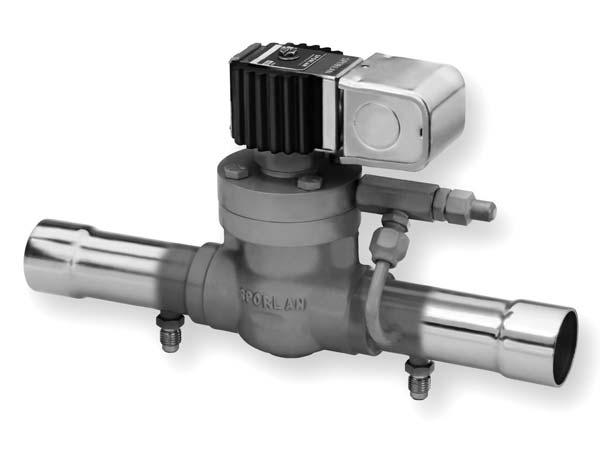
2 Page 2 / Bulletin SPORLAN DEFROST DIFFERENTIAL PRESSURE REGULATING VALVES OFFER THESE BENEFITS: Able to maintain a differential pressure between the defrost header and the liquid header, allowing reverse flow during the defrost cycle. Combines a liquid differential valve and a solenoid valve into one component, thus reducing piping costs. Ability to adjust the differential setting from 5 to 50 psid. In many supermarket applications refrigerant gas from the discharge line, or from the top of the receiver, is used for defrost. This method of defrost diverts a portion of the hot gas or cool gas (from the top of the receiver) to the suction line, and back through the evaporator being defrosted. The gas condenses in the evaporator and flows in reverse, through a check valve, around the TEV and liquid line solenoid valve. Liquid refrigerant then flows to the liquid header where it is distributed to evaporators not in the defrost cycle. In order for reverse flow to occur, the pressure of the defrost header must be greater than the pressure of the liquid header. The difference in pressure is known as the defrost differential. Several methods are used to obtain the defrost differential. A common liquid line method is to install a differential check valve in parallel with a solenoid valve between the receiver and the liquid header. When the solenoid valve is closed during defrost, it allows the differential check valve to control the receiver at a greater pressure than the liquid header. Sporlan offers the (O)LDR-15, (O)LDR-20, XTM and XTO versions for this application. The (O)LDR, XTM or XTO valves combine the features of the liquid differential check valve and the solenoid valve into a single component. A discharge line method is to install a discharge differential pressure regulating valve in the discharge line before the condenser. In order for the reverse flow of hot gas to occur, the pressure of the discharge gas (defrost header) must be greater than the pressure of the receiver (liquid header). Sporlan offers the DDR-20 for this application. A solenoid feature allows the valve to control the differential when the coil is de-energized and to operate full open when the coil is energized. OPERATION (O)LDR, XTM AND XTO VALVE DESIGN & OPERATION The (O)LDR is designed to maintain a differential pressure between the receiver and the liquid header. A pilot differential valve controls the (O)LDR by varying the pressure on top of the main piston. These valves are available in two port sizes, the (O)LDR-15 (1") and the (O)LDR-20 (1-5/16"). Inlet pressure enters the pilot assembly through a passageway in the valve body on the (O)LDR-15, and through an external tube connected to the inlet fitting on the (O)LDR-20. The outlet on the pilot differential valve is connected to the outlet fitting with an external tube on both valves. Sporlan liquid line differential valves have a solenoid bypass feature that allows the valve to remain full open or modulate to maintain a differential. We supply two versions of liquid line differential valves: The OLDR is in the full open position when the coil is de-energized (Figure 3), and it is in the differential operation mode when the coil is energized (Figure 1). The OLDR uses the coil. Refer to Bulletin for more information on Sporlan solenoid coils. The LDR is in the differential operation mode when the coil is de-energized (Figure 2), and it is in the full open position when the coil is energized (Figure 4). The LDR uses the coil. Refer to Bulletin for more information on Sporlan solenoid coils. The XTM operates identically to the LDR-15 and the XTO operates identically to the LDR-20. The special feature of the XTM and XTO versions are the unique outlet fitting configurations. Different outlet fittings are indicated by a suffix -1, -4, or -5 (i.e. the XTM-1 has connections 1-3/8" ODF x 1-3/8" ODF 90 elbow). For piping considerations, if replacement is necessary, an exact replacement is best. The internal parts are interchangeable between the LDR-15 and the XTM, and between the LDR-20 and XTO. Refer to the Specification table on page 8 for further details, and Bulletin for service and installation instructions. (O)LDR, XTM AND XTO DIFFERENTIAL OPERATION OLDR - Coil Energized LDR, XTM and XTO - Coil De-energized The plunger lifts off the pilot port, allowing inlet pressure to enter the chamber on top of the main piston. It then bleeds out through the pilot differential valve (See Figures 1 and 2). When the differential pressure across the valve is below the setting of the pilot differential valve, the pilot differential valve modulates closed. Closing the pilot differential valve allows pressure to build on top of the main piston. As this FOR USE ON REFRIGERATION and/or AIR CONDITIONING SYSTEMS ONLY Bulletin 90-50, April 2004, supersedes Bulletin 90-50, dated May 1999, and all prior publications. Copyright 2004 By Sporlan Company, Washington, MO 63090
3 Bulletin / Page 3 Coil Energized OLDR-20 Differential Operation Coil De-Energized OLDR-20 Full Open Operation Coil Coil Pilot Port Pilot Differential Pilot Port Pilot Differential P2 Spring Strainer P2 Spring Strainer Figure 1 Figure 3 Coil De-energized LDR-20 & XTO Differential Operation Coil Energized LDR-20 & XTO Full Open Operation Coil Coil Pilot Port Pilot Differential Pilot Port Pilot Differential P2 Spring Strainer P2 Spring Strainer Figure 2 Figure 4 pressure () approaches the inlet pressure (), the force, combined with the force from the spring (P2), pushes the piston down, modulating the valve in the closing direction. As the differential pressure rises above the pilot differential valve setting, the pilot differential valve modulates open. This bleeds refrigerant from the chamber on top of the piston at a faster rate than refrigerant is entering, so the pressure () decreases. As this pressure () plus the pressure from the spring (P2) falls below the inlet pressure (), the inlet pressure pushes the piston up, modulating the valve open. The valve will open only as far as necessary to maintain the pilot differential valve setting. The pilot differential valve will then modulate the piston from partially open to partially closed to maintain the valve setting. (O)LDR, XTM AND XTO FULL OPEN OPERATION OLDR - Coil De-energized LDR, XTM and XTO - Coil Energized The plunger moves down to close the pilot port, stopping all flow to the chamber above the piston. The refrigerant remaining above the piston then bleeds to the valve outlet through an orifice (bleed hole) in the pilot differential valve piston. The pressure in the chamber () decreases so the inlet pressure () moves the piston up and the valve opens (See Figures 3 and 4). DDR-20 VALVE DESIGN AND OPERATION The DDR-20 is designed to create a differential pressure between its inlet (discharge) pressure and the receiver pressure. The pilot differential valve controls the DDR-20 by varying the pressure on top of the main piston. The pilot differential valve senses receiver
4 Page 4 / Bulletin pressure through a field installed pilot line connecting the pilot differential valve to the receiver. Inlet pressure enters the pilot assembly through an external tube. This inlet pressure bleeds through a fixed restrictor to the top of the main valve piston. Pressure on top of the main piston is bled off through the pilot differential valve. A solenoid bypass feature is incorporated in the valve so that the valve will modulate fully open when there is no need to create a differential. Energizing the solenoid coil opens the valve fully. The DDR-20 uses the coil. Refer to Bulletin for more information on Sporlan solenoid coils. DDR-20 DIFFERENTIAL OPERATION Coil De-energized The kick-off spring forces the pin and plunger down, closing Port A and opening Port B. Discharge gas enters the chamber on top of the piston through Port B, and is bled out through the pilot differential valve, to the receiver (See Figure 5). When the differential pressure between the discharge line and the receiver is below the setting of the pilot differential valve, the pilot differential valve modulates closed. Closing the valve allows pressure to build on top of the main piston. As this pressure () approaches the inlet pressure (), the force, combined with the force from the spring (P2), pushes the piston down, modulating the valve closed. As the differential pressure rises above the pilot differential valve setting, the pilot differential valve modulates open. The open pilot differential valve bleeds refrigerant from the chamber on top of the piston at a faster rate than refrigerant is entering, therefore the pressure decreases. As this pressure () plus the pressure from the spring (P2) falls below the inlet pressure (), the inlet pressure pushes the piston up, modulating the valve open. The valve opens only as far as necessary to maintain the pilot differential valve setting. The pilot differential valve then modulates the piston from partially open to partially closed to maintain the valve setting. DDR-20 FULL OPEN OPERATION Coil Energized Energizing the solenoid pulls the pin and plunger up, opening Port A. The discharge gas entering the pilot assembly then forces the small ball up to close Port B (See Figure 6). When Port B is closed, discharge gas can no longer enter the chamber on top of the main piston. The pilot differential valve closes, and refrigerant from the top of the piston bleeds to the suction line through Port A and Fitting C. This decreases pressure in the chamber (), so the inlet pressure () moves the piston up and the valve opens. APPLICATION Defrost Differential Pressure Regulating s are used on supermarket systems to allow reverse flow of refrigerant gas through the suction line and evaporator during a defrost. The valves accomplish this by maintaining the defrost header at a greater pressure than the liquid header. Correct application depends Figure 5 Coil De-Energized Differential Operation Figure 6 Coil Energized Full Open Operation Top View Fitting "C" to Suction To Receiver Fitting C Fitting "C" to Suction To Receiver 200 Mesh Strainer 200 Mesh Strainer P2 (Spring) P2 (Spring) Port A Port B Port A Port B
5 Bulletin / Page 5 on several factors. Either of the two types of defrost differential pressure regulating valves (liquid line or discharge line) can be applied on supermarket systems. However, the two types cannot be applied on the same system. LOCATION AND PIPING The (O)LDR, XTM and XTO valves are located between the receiver and the liquid header (See Figure 8). The DDR-20 is located in the discharge line before the condenser (See Figure 7). The two types of defrost differential valves (liquid line and discharge line) cannot be applied on the same system. Sporlan recommends consulting recognized piping references for assistance in piping procedures. Sporlan is not responsible for system design, any damage arising from faulty system design, or for misapplication of its products. If these valves are applied in any manner other than as described in this bulletin or other Sporlan literature, the Sporlan warranty is void. IMPORTANT: There are two pilot lines from the DDR- 20 that must be installed in the field for the valve to operate properly. The 1/4 SAE fitting on the pilot dif- ferential valve must be connected to the receiver. The second 1/4 SAE fitting, located below the solenoid coil (Fitting C), must be connected to the suction line. The pilot line to suction is not a constant high to low side bleed. It only bleeds the small amount of refrigerant from the top of the valve s main piston to open the valve when the solenoid coil is energized. Once the valve is open, and at all other times, there is no high to low side bleed. When the valve is modulating, the bleed through the pilot differential valve is to the receiver. ADJUSTMENT RANGE AND PRESSURE SETTINGS All defrost differential valves are set by turning the adjusting stem located under the cap on the pilot differential valve. The adjustment range is 5 to 50 psig. The (O)LDR, XTM and XTO have a factory setting of 18 psid, and the DDR-20 has a factory setting of 30 psid. Turning the stem clockwise increases the setting, counterclockwise decreases the setting. Adjustments must be made with the valve in its differential mode and no refrigerated cases in defrost, so that the head pressure is normal. Complete instructions on setting the valves are given in Bulletin Figure 7 Typical Piping Diagram with DDR-20 Discharge Differential Regulator DDR-20 Discharge Differential Regulator 8D, 12D, 16D, Heat Reclaim Normal Condenser ORI Head Pressure Control OCV, Oil Check OR-1-1/2 Oil Reservoir Check Reclaim Condenser Type ORD-4 Discharge Bypass Receiver Pressurization Suction Filter Oil Filter PIPING KEY Oil Level Control Oil Separator Suction Discharge Liquid Oil Suction Header Defrost Header Restrictor of some type may be required Suction Throttling or Solenoid Stop for Defrost 2-Way Solenoid Defrost CDS-9 Step Motor Evaporator Control 2-Way Solenoid Defrost Reclaim Condenser Pump-out Solenoid (normally open) Evaporator Evaporator Catch-All Distributor TEV Check TEV Check See All Liquid Line Solenoid Check Liquid Header Liquid Line Solenoid with Check Feature (CE Series) Receiver
6 Page 6 / Bulletin Figure 8 Typical Piping Diagram with (O)LDR-20 Liquid Differential Regulator 8D, 12D, 16D, Heat Reclaim Normal Condenser ORI Head Pressure Control OCV, Oil Check OR-1-1/2 Oil Reservoir Check Reclaim Condenser Type ORD-4 Discharge Bypass Receiver Pressurization Suction Filter Oil Filter PIPING KEY Oil Level Control Oil Separator Suction Discharge Liquid Oil Suction Header Defrost Header Restrictor of some type may be required Suction Throttling or Solenoid Stop for Defrost 2-Way Solenoid Defrost CDS-9 Step Motor Evaporator Control 2-Way Solenoid Defrost Reclaim Condenser Pump-out Solenoid (normally open) Evaporator Evaporator Catch-All Distributor TEV Check TEV Check See All Liquid Line Solenoid (O)LDR Liquid Differential Regulator Check Liquid Header Liquid Line Solenoid with Check Feature (CE Series) Receiver SELECTION Selection involves five basic system criteria: 1. Refrigerant 2. The type of Defrost Differential (Liquid Differential Pressure Regulating or Discharge Differential Pressure Regulating ) 3. Allowable design pressure drop across the valve 4. Liquid temperature 5. Common suction temperature A normally open OLDR version or an LDR version (differential mode when the coil is de-energized) must be determined if a liquid differential pressure regulating valve is desired. Example: Select a Liquid Defrost Differential Pressure Regulating for a 40 ton R-22 supermarket system with a liquid temperature of 90 F and a common suction temperature of 0 F. From the capacity table on page 7, the (O)LDR-15 has a capacity of 46.9 tons at a 2 psi pressure drop. The correction factor for 90 F liquid is 1.06, and the correction factor for 0 F suction is Therefore 46.9 tons multiplied by 1.06 and 0.91 is equal to 45.2 tons. The OLDR-15-5/50 is the appropriate selection. Example: Select a Discharge Differential Pressure Regulating for a 20 ton R-404A supermarket system with a liquid temperature of 60 F and a common suction of -20 F. From the capacity table on page 7, the DDR-20 has a capacity of 18.7 tons at a 2 psi pressure drop. The correction factor for 60 F liquid is 1.43 and the correction factor for -20 F suction is Therefore 18.7 tons multiplied by 1.43 and 0.85 is equal to 22.7 tons. The DDR-20-5/50 is the appropriate selection.
7 Bulletin / Page 7 CAPACITIES - TONS OF REFRIGERATION REFRIGERANT a 404A/507 PRESSURE DROP ACROSS VALVE - psi TYPES LDR-15, OLDR-15 & XTM TYPES LDR-20, OLDR-20 & XTO TYPE DDR Capacities are based on 40 F evaporator temperature, 100 F condenser temperature, 25 F superheated return gas, discharge gas temperature 50 F above isentropic compression. For capacities at other liquid or evaporator temperatures use multipliers in table below: REFRIGERANT LIQUID TEMPERATURE F REFRIGERANT LIQUID TEMPERATURE CORRECTION FACTORS A EVAPORATOR TEMPERATURE CORRECTION FACTORS EVAPORATOR TEMPERATURE F Multiplier DESIGNATION / ORDERING INSTRUCTIONS Select from the capacity table above. When ordering be sure to give complete valve designation including voltage and cycles. OLDR O LDR 15 5/50 1-3/8 ODF 120/50-60 Normally Open DDR Liquid Differential Regulator Size Adjustment Range - psi Connections - Inches Electrical Specifications DDR 20 5/50 1-5/8 ODF 120/50-60 Discharge Differential Regulator Size Adjustment Range - psi Connections - Inches Electrical Specifications
8 Page 8 / Bulletin VALVE TYPE PORT SIZE Inches * Add 1 pound for solenoid coil. The XTM-1, XTM-5, XTO-1 and XTO-4 are Underwriters Laboratories Listed under Guide No. YIOZ, File No. MH4576. Maximum Rated Pressure of 400 psig. MOPD of 300 psig. OLDR-15 DIFFERENTIAL SETPOINT RANGE SPECIFICATIONS CONNECTIONS - Inches INLET x OUTLET DIMENSIONS - Inches COIL A B C D Net WEIGHT - lbs* Shipping OLDR /8 ODF x 1-1/8 ODF or LDR /8 ODF x 1-3/8 ODF OLDR /8 ODF x 1-5/8 ODF /16 or LDR /8 ODF x 2-1/8 ODF XTM-1 5/50 psi 1-3/8 ODF x 1-3/8 ODF, 90 Elbow XTM-5 1-1/8 ODF x 1-3/8 ODF, 90 Elbow XTO-1 1-5/8 ODF x 1-5/8 ODF, 90 Elbow /16 XTO-4 2-1/8 ODF x 2-1/8 ODF DDR /16 1-5/8 ODF x 1-5/8 ODF See drawing below C XTM C B A D NOTE: (O)LDR-15 size valves do not have the tube from inlet fitting to pilot assembly. Inlet pressure enters the pilot assembly through a passageway in the valve body. DDR A 2.06 D B PRINTED IN U.S. OF A
Condensed Catalog 410A January 2008
 CATALOG Page 1 Condensed Catalog January 2008 This condensed catalog contains product specifically for R- applications. By including a minimum of engineering information we are able to provide a concise
t EVAPORATOR PRESSURE REGULATING VALVES
 CATALOG 201 Page 63 t EVAPORATOR PRESSURE REGULATING VALVES (S)ORIT-12, -15 and -20 Features n High side pilot for improved temperature control and low P operation n Adjustable n Optional solenoid stop
Defrost Differential Pressure Regulating Valves Installation and Service Instructions
 July 202 / Bulletin 90-5 Defrost Differential Pressure Regulating s Installation and Service Instructions (O)LDR-6, (O)LDR-20, DDR-20 Obsolete: (O)LDR-5, XTM-, XTM-5, XTO-, -4 (Included for part s breakdown)
Hot gas bypass regulator type CPCE Liquid gas mixer type LG (accessory)
") MAKING MODERN LIVING POSSIBLE Data sheet Hot gas bypass regulator type CPCE Liquid gas mixer type LG (accessory) A CPCE hot gas bypass regulator is used to adapt compressor capacity to actual evaporator
MAKING MODERN LIVING POSSIBLE Data sheet Hot gas bypass regulator type CPCE Liquid gas mixer type LG (accessory) A CPCE hot gas bypass regulator is used to adapt compressor capacity to actual evaporator
The System Features These Advantages: Designing the Low Pressure Oil Return System
 JANUARY 2004 / Bulletin 110-10 Sporlan s Oil Level Control System components were developed to offer the refrigeration industry an oil level control system of the highest quality. The heart of the system
611H Flo-Con Pressure Regulators & Valves
 aerospace climate control electromechanical filtration fluid & gas handling hydraulics pneumatics process control sealing & shielding 611H Flo-Con Regulators & Valves Catalog F-2, February 2012 Page 2
Pulse Width Modulation Valves. Models SPW-0 thru -7
 November 2017 Bulletin / Bulletin 30-30 30-30 Page 1 Pulse Width Modulation s Models SPW-0 thru -7 Page 2 Bulletin 30-30 Pulse Width Modulation s For Refrigerant Flow Control in Direct Expansion HFC, HCFC
April 2007 / BULLETIN Solenoid Valves. The right solenoid valve for any job.
 pril 2007 / BULLETIN 30-10 Solenoid Valves The right solenoid valve for any job. Bulletin 30-10 / Page 1 Sporlan Solenoid Valves Benefits Molded coil for most sizes. lass "F" temperature rating oil types
Refrigeration Solenoid Valves & 3-Way Heat Reclaim Valves
 aerospace climate control electromechanical filtration fluid & gas handling hydraulics pneumatics process control sealing & shielding Refrigeration Solenoid s & 3-Way Heat Reclaim s Catalog D-1, May 2010
Subcritical CO 2 Innovations
 March 2011 / CATALOG 744 Subcritical CO 2 Innovations Energy Conscious Products & Solutions for Supermarkets Subcritical CO 2 Innovations Energy Conscious Products & Solutions for Supermarkets CATALOG
PRODUCT DATA HDF SERIES Solenoid Valve
 HDF series solenoid valves are piston type pilot operated solenoid valves, and are designed for use in all air conditioning and refrigeration systems. The HDF valves can tolerate discharge line temperatures
Solenoid Valves. Installation and Servicing Instructions SD-15/ TYPES B6, B9, B10, B14, B19, B25 SERIES (Brass Connections) GENERAL
 GENERAL") Solenoid Valves Installation and Servicing Instructions SD-15/82017 The molded MKC-1 coil fits the E2, A3, E3, W3, S4, E5, B6, E6, S6, W6, S7, E8, E10S1, E35, E43, R183, R184 and R246 series normally closed
Solenoid Valves Installation and Servicing Instructions SD-15/82017 The molded MKC-1 coil fits the E2, A3, E3, W3, S4, E5, B6, E6, S6, W6, S7, E8, E10S1, E35, E43, R183, R184 and R246 series normally closed
November 2015 / BULLETIN Solenoid Valves. Installation and Servicing Instructions ENGINEERING YOUR SUCCESS
 Solenoid Valves Installation and Servicing Instructions November 2015 / BULLETIN 30-11 ENGINEERING YOUR SUCCESS Page 2 / Bulletin 30-11 Solenoid Valves Installation and Servicing Instructions Not For Use
(S)PORT - (S)PORT-II Evaporator Pressure Regulators
PORT - (S)PORT-II Evaporator Pressure Regulators") (S)PORT - (S)PORT-II Evaporator Pressure Regulators Features Highest capacity commercial regulator in the industry Sweat-in-place without disassembly Interchangeable capacity cartridges Low Pressure Drop
(S)PORT - (S)PORT-II Evaporator Pressure Regulators Features Highest capacity commercial regulator in the industry Sweat-in-place without disassembly Interchangeable capacity cartridges Low Pressure Drop
3-Way Valves. Installation and Servicing Instructions
 June 001 / ULLETIN 30-1 3-Way Valves Installation and Servicing Instructions CONTENTS 5D, 8D, 1D & 16D 3-Way Heat Reclaim Valves................ 8D-SC, 1D-SC & 16D-SC 3-Way Split Condenser Valves........
Solenoid valve for R410A and R744 Types EVR 2 - EVR 6 and EVRH 10 - EVRH 40
 Data sheet Solenoid valve for R410A and R744 s EVR 2 - EVR 6 and EVRH 10 - EVRH 40 EVRH high pressure range is a direct or servo operated solenoid valve specially designed to meet the requirements for
Solenoid valves type EVR 2 40 NC / NO
 Solenoid valves type EVR 2 40 NC / NO Introduction EVR is a direct or servo operated solenoid valve for liquid, suction, and hot gas lines with fluorinated refrigerants. Features Complete range of solenoid
MAKING MODERN LIVING POSSIBLE. Solenoid valves Type EVU for fluorinated refrigerants REFRIGERATION AND AIR CONDITIONING.
 MAKING MODERN LIVING POSSIBLE Solenoid valves EVU for fluorinated refrigerants REFRIGERATION AND AIR CONDITIONING Technical leaflet Contents Page Introduction... 3 Features... 3 Approvals... 3 Technical
EVAPORATOR PRESSURE REGULATORS
 PARKER (S)PORT, (S)PORT II FEATURES AND BENEFITS Highest capacity commercial regulator in the industry. Sweat-in-place without disassembly. Interchangeable capacity cartridges. Low pressure drop. Manual
Specifications, Applications, Service Instructions & Parts. Flanged and Weld-in 3/4" thru 4" Port (20 mm thru 100 mm) for Refrigerants
 for Refrigerants") Bulletin Specifications, Applications, Service Instructions & Parts Hs4d TWO STEP solenoid valves Flanged and Weld-in 3/4" thru 4" Port (20 mm thru 100 mm) for Refrigerants 2 (50 mm) HS4D with Optional
Bulletin Specifications, Applications, Service Instructions & Parts Hs4d TWO STEP solenoid valves Flanged and Weld-in 3/4" thru 4" Port (20 mm thru 100 mm) for Refrigerants 2 (50 mm) HS4D with Optional
Thermostatic and Automatic Expansion Valves
 aerospace climate control electromechanical filtration fluid & gas handling hydraulics pneumatics process control sealing & shielding Thermostatic and Automatic Expansion Valves Catalog E-1, July 2012
Pilot operated main valves for regulating pressure and temperature, type PM
 MAKING MODERN LIVING POSSIBLE Technical brochure Pilot operated main valves for regulating pressure and temperature, type PM PM valves are pilot operated main valves for regulating pressure and temperature
Danfoss Saginomiya 4 - Way Reversing Valves
 New perspectives with anfoss Saginomiya - Way Reversing Valves Reliable season change ST, VHV -way reversing valves Wide application range - complete capacity range - available for all common refrigerants
Crankcase Pressure Regulating Valves
 Crankcase Regulating Valves Crankcase Regulating Valves are designed to prevent overloading of the compressor motor by limiting the crankcase pressure to a predetermined maximum value during and after
Electrical Control Valves Series EX4, EX5, EX6, EX7 & EX8
 Electrical Control s Series EX4, EX5, EX6, EX7 & EX8 Features Multifunction as expansion valve, hot gas bypass, suction gas throttling, head pressure, liquid level actuator etc. Fully hermetic design (no
Solenoid valve. Solenoid Coil
 Solenoid valve Solenoid valve Solenoid Coil Plunger Valve body A simple solenoid valve consists ofi: Valve body with a plunger the plunger is made of metal Coil an electrical coil if the coil is given
Solenoid valve Types EVR 2 EVR 40 NC/NO
 MAKING MODERN LIVING POSSIBLE Data sheet Solenoid valve s EVR 2 EVR 40 NC/NO EVR is a direct or servo operated solenoid valve for liquid, suction, and hot gas lines with fluorinated refrigerants. EVR valves
Reliable season change
 New perspectives with Danfoss Saginomiya 4 - Way Reversing Valves Reliable season change, VHV 4-way reversing valves Wide application range - complete capacity range - available for all common refrigerants
Sporlan Gas Cooler/ Flash Gas Bypass Valves
 Sporlan Gas Cooler/ Flash Gas Bypass Valves For Transcritical CO 2 (R-744) Applications August 14 / Bulletin 100-80 Page 2 Bulletin 100-80 Bulletin 100-80 Page 3 GAS COOLER/FLASH GAS BYPASS VALVES The
EX4 / EX5 / EX6 / EX7 / EX8 Electrical Control Valves
 ALCO Controls EX4 / EX5 / EX6 / EX7 / EX8 are stepper motor driven valves for precise control of refrigerant mass flow in air conditioning, refrigeration, heat pumps, close control, and industrial process
Solenoid valves Type EVU for fluorinated refrigerants
 Data sheet Solenoid valves EVU for fluorinated refrigerants EVU solenoid valves are designed to fit into compact refrigeration systems. Available in direct and pilot operated versions, they can be applied
Solenoid valves Type EVR 2 40 NC/ NO REFRIGERATION AND AIR CONDITIONING. Technical leaflet
 Solenoid valves EVR 2 40 NC/ NO REFRIGERATION AND AIR CONDITIONING Technical leaflet 2 DKRCCPDBB0A202-520H275 Danfoss A/S, 0-2006 Contents Page Introduction.......................................................................................
Electrical Control Valves
 172 Electrical Control Valves Electrical Control Valves Electrical Control Valve Technology Thermostatic expansion valves and mechanical regulator valves have been used in the refrigeration and air conditioning
Low Profile Unit Coolers
 Bulletin 306.0D August 2004 (Replaces 306.0C 3/04) Low Profile Unit Coolers Model ADT - Air Defrost Model LET/LLE - Electric Defrost Model HGT - Hot Gas Defrost Front access to refrigeration components.
SOLENOID VALVES SOLDER CONNECTIONS
 SOLEID VALVES I n s t a l l a t i o n a n d S e r v i c i n g I n s t ru c t i o n s N O T F O R U S E O N H A Z A R D O U S O R C O R R O S I V E F L U I D S The molded MKC- coil fits the A3, E3, W3,
Reliable season change
 ew perspectives with anfoss Saginomiya 4 - Way Reversing Valves Reliable season change ST, VHV 4-way reversing valves Wide application range - complete capacity range - available for all common refrigerants
Solenoid valves. Solenoid valves, type PKVD Solenoid valves, type EVR NC / NO
 Solenoid valves Contents Page Solenoid valves, type PKVD 12-20 Introduction... 5 Features... 5 Technical data... 5 Ordering... 5 Capacity... 6 Sizing... 7 Valve selection... 7 Design/Function... 8 Dimensions
Why and how to adjust a TXV / TEV
 Why and how to adjust a TXV / TEV As we talked about in an earlier podcast, a TXV is designed to maintain a specified and constant superheat at the outlet of the evaporator coil. It does this through a
800SVRM-7 5/04 RATE-OF-FLOW CONTROL 800 SERIES CONTROL VALVES
 RATE-OF-FLOW CONTROL RATE-OF-FLOW WITH SOLENOID & EXTERNAL FILTER.2 .3 RATE-OF-FLOW & PRESSURE REDUCIN G WITH SOLENOID & EXTERNAL FI LTER.4 RATE-OF-FLOW & PRESSURE SUSTAINING WITH EXTERNAL FILTER.5 RATE-OF-FLOW
ANSI/AHRI Standard 760 (I-P) 2014 Standard for Performance Rating of Solenoid Valves for Use with Volatile Refrigerants
 2014 Standard for Performance Rating of Solenoid Valves for Use with Volatile Refrigerants") ANSI/AHRI Standard 760 (I-P) 2014 Standard for Performance Rating of Solenoid Valves for Use with Volatile Refrigerants Approved by ANSI on May 15, 2015 IMPORTANT SAFETY DISCLAIMER AHRI does not set safety
ANSI/AHRI Standard 760 (I-P) 2014 Standard for Performance Rating of Solenoid Valves for Use with Volatile Refrigerants Approved by ANSI on May 15, 2015 IMPORTANT SAFETY DISCLAIMER AHRI does not set safety
Pilot controlled servo valves Type ICS - Solenoid Valves Pressure Regulating Valves. Technical leaflet MAKING MODERN LIVING POSSIBLE
 MAKING MODERN LIVING POSSIBLE Pilot controlled servo valves Type ICS - Solenoid Valves Pressure Regulating Valves REFRIGERATION AND AIR CONDITIONING Technical leaflet Contents Page Introduction...3 Features...3
Pilot Controlled Servo Valves ICS
 MAKING MODERN LIVING POSSIBLE Technical brochure Pilot Controlled Servo Valves ICS ICS servo valves belong to the ICV (Industrial Control Valve) family and are one of two product groups. ICV types ICS
Solenoid valves type EVRA 3 to 40 and EVRAT 10 to 20
 Solenoid valves type EVRA 3 to 40 and EVRAT 10 to 20 Contents Page Approval...569 Technical data...569 Ordering...570 Rated capacity...573 Capacity...573 Design / Function...577 Material specification............................................................................
Electrically Operated Expansion Valve Types AKV 10, AKV 15 and AKV 20
 MAKING MODERN LIVING POSSIBLE Data sheet Electrically Operated Expansion Valve Types AKV 10, AKV 15 and AKV 20 AKV are electrically operated expansion valves designed for refrigerating plants. The AKV
THERMOSTATIC EXPANSION VALVES
 PARKER TXV MODEL NUMBER SELECTION S MODEL E EXTERNAL EQUALIZER OPTIONAL 5 V X CHARGE TYPE 00 M.O.P. B BLEED OPTIONAL 0 BLEED S EG (C) C = Internal Check Valve (E) for externally equalized evaporator pressure
Pilot-operated servo valve Type ICS
 Data sheet Pilot-operated servo valve Type ICS ICS pilot-operated servo valves belong to the ICV (Industrial Control Valve) family. The valve comprises three main components: valve body, function module
Appendix A. Standard Symbols for Hydraulic Components
 Table B.1 Flow lines Appendix A Standard Symbols for Components Continuous flow E Pilot connection L L>10E E Drain connection L L
Solenoid valves Type EVU
 Data sheet Solenoid valves EVU EVU solenoid valves are designed to fit into compact refrigeration systems. Available in direct and servo operated versions, they can be applied in liquid, suction, and hot
Industrial Refrigeration Control Valves. Catalog C12
 aerospace climate control electromechanical filtration fluid & gas handling hydraulics pneumatics process control sealing & shielding Industrial Refrigeration Control Valves Catalog C Refrigerating Specialties
Product Guide for HFO / HFO Blends. R448A/R449A R450A/R513A R1234ze. R134a R407A/F R404A/507 R12/502
 Product Guide 2016 for HFO / HFO Blends R448A/R449A R450A/R513A R1234ze R134a R407A/F R404A/507 R12/502 Preface Many end-users, equipment and compressor manufacturers are investigating ways to minimize
Pilot-operated servo valve Type ICS
 Data sheet Pilot-operated servo valve ICS ICS pilot-operated servo valves belong to the ICV (Industrial Control Valve) family. The valve comprises three main components: valve body, function module and
Copeland Screw TM Compressors
 Copeland Screw TM Compressors Mechanical Guidelines for SHL & SHM Models using ESC-201 Control System Contents: Start-Up Procedure Operating Specifications Maintenance Trouble Shooting Guidelines Start-up
Alco Controls. Components for the Refrigeration Industry. Product Selection Catalogue
 Alco Controls Components for the Refrigeration Industry Product Selection Catalogue Note: The components listed in this catalogue are not released for use with caustic, poisonous or flammable substances.
Parker TEV Model Visual
 PARKER - THERMOSTATIC EXPANSION VALVES TXV MODEL NUMER SELECTION Parker TEV Model Visual N Series TEV C(E) Series TEV SC(E) Series TEV Applications: Applications: Applications: Low Profile Coolers, Rail
PRESSURE REDUCING VALVE
 Schematic Throttles to reduce high upstream pressure to constant lower downstream pressure Low Flow By-Pass controls at low flows 4 PRESSURE REDUCING VALVE with LOW-FLOW BY-PASS FEATURE Main Line valve
PRESSURE REDUCING VALVE
 Schematic Throttles to reduce high upstream pressure to constant lower downstream pressure Low Flow By-Pass controls at low flows 4 PRESSURE REDUCING VALVE with LOW-FLOW BY-PASS FEATURE Main Line valve
BULLETIN Type A4AM. March 2002 Installation, Service and Parts Instruction. Refrigerating Specialties Division Fig.
 Electrically Compensated Pressure Regulators Type A4AM, A4AOM, & A2BM PORT SIZE 3/8-4 (20MM-100MM) FOR AMMONIA, R22, R134A, R502 OTHER COMMON REFRIGERANTS FEATURES Unique modular construction Suitable
MODULOAD CAPACITY CONTROL FOR 3D COMPRESSORS
 21-1278 Application Engineering Bulletin AE-1278-R5 Revised February, 1997 MODULOAD CAPACITY CONTROL FOR 3D COMPRESSORS On refrigeration and air conditioning applications where the refrigeration load may
Solenoid valves type EVSA 25 50
 Solenoid valves type EVSA 25 50 Introduction EVSA is an assisted lift, servo operated solenoid valve. EVSA 25, 35 and 50 are for use in suction lines - EVSA 25 in liquid and return lines too - in refrigerating
Pressure and temperature regulators, type PM, and pilot valves
 Pressure and temperature regulators, type PM, and pilot valves Introduction Main valves, type PM 1 and PM 3 Pilot valves for mounting directly into main valves, type PM Main valves, type PM 1 and PM 3
(770) Turning Parts Changers Into TROUBLESHOOTERS!
 Turning Parts Changers Into TROUBLESHOOTERS!") Hydraulic Consulting, Inc. Turning Parts Changers Into TROUBLESHOOTERS! This e-book manual is your customized troubleshooting manual in Adobe Acrobat Portable Document File (PDF) format. It requires the
Hydraulic Consulting, Inc. Turning Parts Changers Into TROUBLESHOOTERS! This e-book manual is your customized troubleshooting manual in Adobe Acrobat Portable Document File (PDF) format. It requires the
REFRIGERATION STRAINERS
 REFRIGERATION STRAINERS AC & R OIL FILTER - POE OIL FILTER-DRIER S-4004 AC&R Components S-4004 Oil Filter removes foreign material from the oil as it passes through the filter. The filter easily captures
Pilot-operated servo valve Type ICS
 Data sheet Pilot-operated servo valve Type ICS The valve comprises three main components: valve body, function module and top cover. ICS pilot-operated servo valves are pilot operated valves for regulating
Electric Expansion Valve Type AKVO 10
 Data sheet Electric Expansion Valve Type AKVO 10 AKVO 10 is an electrically operated expansion valve designed for refrigeration plant. AKVO 10 has an internal filter. The AKVO 10 range covers a capacity
PRESSURE REDUCING CONTROL VALVE
 PRESSURE REDUCING CONTROL VALVE 06/08 Schematics Throttles to reduce high upstream pressure to constant lower downstream pressure Reducing setpoint is adjustable 2 (AOS) X P/L Standard Components 1 Main
Capacity regulators (hot gas bypass) PMC and CVC
 PMC and CVC") MAKING MODERN LIVING POSSIBLE Technical brochure Capacity regulators (hot gas bypass) PMC and CVC The PMC and CVC is used for capacity regulation in refrigeration, freezing and air conditioning plant for
MAKING MODERN LIVING POSSIBLE Technical brochure Capacity regulators (hot gas bypass) PMC and CVC The PMC and CVC is used for capacity regulation in refrigeration, freezing and air conditioning plant for
Solenoid valves EVRA and EVRAT
 Data sheet Solenoid valves EVRA and EVRAT EVRA is a direct or servo operated solenoid valve for liquid, suction and hot gas lines with ammonia or fluorinated refrigerants. EVRA valves are supplied complete
Rack Oil regulation and System Oil Failures
 Rack Oil regulation and System Oil Failures Bryan Lord 2009 Oil failure alarms are usually more than just a compressor safety control failure or low oil pressure event. Unfortunately OFC alarms are just
MAINTENANCE MANUAL FOR THERMOSTATIC TEMPERATURE REGULATING VALVE TRAC STYLE P
 MANUAL NUMBER P-EFS-1 MAINTENANCE MANUAL FOR THERMOSTATIC TEMPERATURE REGULATING VALVE TRAC STYLE P TRAC Regulator Company Inc. 160 South Terrace Avenue Mount Vernon, New York USA 10550-2408 Phone: (914)
Product Guide for HFO / HFO Blends. R448A/R449A R450A/R513A R1234ze. R134a R407A/F R404A/507 R12/502
 Product Guide 2016 for HFO / HFO Blends R448A/R449A R450A/R513A R1234ze R134a R407A/F R404A/507 R12/502 Preface Many end-users, equipment and compressor manufacturers are investigating ways to minimize
ESCONDIDO FIRE DEPT TRAINING MANUAL Section DRIVER OPERATOR Page 1 of 13 Pumps and Accessory Equipment Revised
 DRIVER OPERATOR Page 1 of 13 PUMPS AND ACCESSORY EQUIPMENT Pumps are designed for many different purposes. In order to understand the proper application and operation of a pump in a given situation, firefighters
DIFFERENTIAL PRESSURE RELIEF REGULATOR TYPE A4AL Port Size 3/4"- 4" (20-100mm) For Ammonia, R-22, R134a, R404a, R507 and other common refrigerants.
 For Ammonia, R-22, R134a, R404a, R507 and other common refrigerants.") DIFFERENTIAL PRESSURE RELIEF REGULATOR TYPE A4AL Port Size 3/4"- 4" (20-100mm) For Ammonia, R-22, R134a, R404a, R507 and other common refrigerants. FEATURES Pilot operated characterized Modulating Plug
DIFFERENTIAL PRESSURE RELIEF REGULATOR TYPE A4AL Port Size 3/4"- 4" (20-100mm) For Ammonia, R-22, R134a, R404a, R507 and other common refrigerants. FEATURES Pilot operated characterized Modulating Plug
Replacing the Internal Oil Filter Elements for HS85 and OS 85 Screw Compressors
 Maintenance Bulletin (MB-0038) Version 1, Sept 2015 Replacing the Internal Oil Filter Elements for HS85 and OS 85 Screw Compressors The internal oil filter elements are recommended to be changed on new
2003 Explorer Sport/Sport-Trac Workshop Manual. 7. Disconnect the vacuum harness connector. Remove the nut.
 7. Disconnect the vacuum harness connector. Remove the nut. 8. Remove two nuts, one bolt, and the A/C evaporator housing (19850). Remove the nut located at the bottom of the A/C evaporator housing first.
HFK. Balanced Port Thermo Expansion Valve Kits. Save Inventory $ and Valuable Truck Stock Space
 HFK Balanced Port Thermo Expansion Valve Kits Save Inventory $ and Valuable Truck Stock Space Features and Benefits Features of the high performance HF valve now available with interchangeable valve bodies,
P SERIES INTENSIFIER PUMP
 P SERIES INTENSIFIER PUMP INSTALLATION, OPERATION & MAINTENANCE MANUAL INTERFACE DEVICES, INC. 230 Depot Road, Milford, CT 06460 Ph: (203) 878-4648, Fx: (203) 882-0885, E-mail: info@interfacedevices.com
2003 Mustang Workshop Manual
 Page 1 of 6 SECTION 412-03: Air Conditioning 2003 Mustang Workshop Manual DESCRIPTION AND OPERATION Procedure revision date: 06/14/2002 Air Conditioning Printable View (225 KB) The A/C refrigerant system
Section Va: Valve Actuators
 Valve and Actuator Manual 977 Actuator Basics and Sizing Information Section Engineering Data Book Va Issue Date 0592 Section Va: Valve Actuators Pneumatic Actuators Page 3 Electric Actuators 5 Maximum
June 2015 / BULLETIN Catch-All. Liquid & Suction Line Filter-Driers FILTER-DRIERS. It s the CORE that counts!
 June 2015 / BULLETIN 40-10 Catch-All Liquid & Suction Line Filter-Driers FILTER-DRIERS It s the CORE that counts! Page 2 Bulletin 40-10 Table of Contents The Sporlan Catch-All Liquid and Suction Line Filter-Driers
Solenoid valves, type EVRA 3 40 and EVRAT REFRIGERATION AND AIR CONDITIONING. Technical leaflet
 Solenoid valves, type 40 and EVRAT 10 20 REFRIGERATION AND AIR CONDITIONING Technical leaflet Technical leaflet Solenoid valves type to 40 and EVRAT 10 to 20 Contents Page Introduction... 3 Approvals...
AE R5 February 1997 Reformatted November 2010
 AE21-1278 R5 February 1997 Reformatted November 2010 Moduload Capacity Control for 3D Compressors On refrigeration and air conditioning applications where the refrigeration load may vary over a wide range,
Electric Expansion Valves
 Electric Expansion s Bulletin 100-20-1, January 2011 Page 2 Bulletin 100-20-1UK This supplement to Bulletin 100-20 (September 2008) details the updated Sporlan series of Electric Expansion s. Built on
Adjustable Differential Relay A1
 Sales Manual Section 332 PRODUCT SPECIFICATION MODEL 84871-A1 GENERAL DESCRIPTION The 84871-A1 Adjustable Differential Diverting Relay is a two-position, snap-acting, three-way relay. Its normal function
Section 6.1. Implement Circuit - General System. General: TF Configuration TB Configurations Implement Control Valve:
 Section 6.1 Implement Circuit - General System General: TF Configuration... 6.1.3 TB Configurations... 6.1.5 Implement Pump Breakdown... 6.1.6 Operational Description: General... 6.1.7 Compensator Control...
Sporlan V-Series Ruby Seat Solenoid Valves
 aerospace climate control electromechanical filtration fluid & gas handling hydraulics pneumatics process control sealing & shielding Sporlan V-Series Ruby Seat Solenoid Valves Bulletin 30-10-8, October
EMERSON CLIMATE TECHNOLOGIES-EX
 EMERSON CLIMATE TECHNOLOGIES-EX Valves & Controls EX4-EX8 Control Valve The EX4-EX8 are stepper motor driven valves that are optimized for the control of liquid or gaseous mass flow in refrigeration systems.
Steel Suction Line Accumulators
 Steel Suction Line Accumulators U-Tube Style Accumulators VA, PA and VPA Series The U-tube accumulator design is a result of extensive laboratory testing of various designs. It takes into account essential
Specifications, Applications, Service Instructions & Parts. HCK1, HCK1W PISTON-TYPE CHECK VALVE ¾" thru 6" (20 thru 150 mm)
") Bulletin Specifications, Applications, Service Instructions & Parts HCK1, HCK1W PISTON-TYPE CHECK VALVE ¾" thru (20 thru 150 mm) d ¾" thru FPT, SW, WN, ODS for refrigerants Piston-Type Check Valve: HCK1
Bulletin Specifications, Applications, Service Instructions & Parts HCK1, HCK1W PISTON-TYPE CHECK VALVE ¾" thru (20 thru 150 mm) d ¾" thru FPT, SW, WN, ODS for refrigerants Piston-Type Check Valve: HCK1
Section 6.1. Implement Circuit - General System. General: Implement Control Valve:
 Section 6.1 Implement Circuit - General System General: Implement Circuit... 6.1.3 Implement Pump Breakdown... 6.1.4 Operational Description: General... 6.1.5 Compensator Control... 6.1.6 Standby Condition...
Mustang Series PRESSURE REDUCING CONTROL VALVE. M115 (Globe) M1115 (Angle) Schematic. Standard Components. Options & Accessories.
 M1115 (Angle) Schematic. Standard Components. Options & Accessories.") PRESSURE REDUCING CONTROL VALVE 02/09 Schematic Throttles to reduce high upstream pressure to constant lower downstream pressure Reducing setpoint is adjustable 2 (AOS) P/L Standard Components 1 Main Valve
PRESSURE REDUCING CONTROL VALVE 02/09 Schematic Throttles to reduce high upstream pressure to constant lower downstream pressure Reducing setpoint is adjustable 2 (AOS) P/L Standard Components 1 Main Valve
Application Data CONTENTS. COMPRESSOR PHYSICAL DATA (Table 1) Table 1 Open-Drive Compressors
 Table 1 Open-Drive Compressors") Page COMPRESSOR PHYSICA DATA................. 1 OPEN-DRIVE COMPRESSORS................ 2-29 Operating Requirements......................... 2 Discharge Temperature.......................... 2 High Compression
Page COMPRESSOR PHYSICA DATA................. 1 OPEN-DRIVE COMPRESSORS................ 2-29 Operating Requirements......................... 2 Discharge Temperature.......................... 2 High Compression
Multi Ejector Solution TM for R744 (CO 2 ) Product type - CTM 1 and CTM 2 Liquid Ejector
 Product type - CTM 1 and CTM 2 Liquid Ejector") Data sheet Multi Ejector Solution TM for R744 (CO 2 ) Product type - CTM 1 and CTM 2 Liquid Ejector Multi Ejector Solution TM, consists of a CTM 1 and CTM 2 liquid valves and an AK-PC 782A controller.
Data sheet Multi Ejector Solution TM for R744 (CO 2 ) Product type - CTM 1 and CTM 2 Liquid Ejector Multi Ejector Solution TM, consists of a CTM 1 and CTM 2 liquid valves and an AK-PC 782A controller.
V46 Series Pressure-Actuated Water-Regulating Valves
 FANs 1, 11 Product/Technical Bulletin V46 Issue Date 9 V46 Series Pressure-Actuated Water-Regulating Valves The V46 pressure-actuated modulating valves come in two types of control action: direct acting
Electric expansion valves Types AKVA 10, 15 & 20
 Data sheet Electric expansion valves Types AKVA 10, 15 & 20 AKVA are electric expansion valves designed for ammonia refrigerating plant. The AKVA valves are normally controlled by a controller from Danfoss
WATER COOLED AIR CONDITIONING UNITS MODEL CVWSEK-060 WATER SIDE ECONOMIZER FOR CSV060B VERTICAL R-410A STYLE B R-410A
 WATER COOLED AIR CONDITIONING UNITS INSTALLATION, OPERATION, & MAINTENANCE SUPERSEDES 145.15-IOM1 (612) Form 145.15-IOM1 (514) MODEL CVWSEK-060 WATER SIDE ECONOMIZER FOR CSV060B VERTICAL R-410A STYLE B
Eclipse 2000 Service Parts
 This part list contains the service parts for the Eclipse 000 systems. The models that are covered include: CME08 CP08 ERC08 Eclipse 000 Service Parts Table of Contents CME08 Cabinet Page CME08 Interior
SOLENOID VALVES FOR REFRIGERATING SYSTEMS
 SOLENOID VALVES 17 SOLENOID VALVES FOR REFRIGERATING SYSTEMS APPLICATIONS The solenoid valves, shown in this chapter, are classified Pressure accessories in the sense of the Pressure Equipment Directive
Daniel. Liquid Control Valves Technical Guide. Technical Guide DAN-LIQ-TG-44-rev0813. DAN-LIQ-TG-44-rev0208. February 2008.
 DAN-LIQ-TG-44-rev0208 February 2008 Daniel Liquid Control Valves Technical Guide www.daniel.com Daniel Measurement and Control Theory, Principle of Operation and Applications This brochure has been prepared
Corp L3 Revised CB17/CBH17 SERIES UNITS SPECIFICATIONS CB17-95V CBH17-95V
 Service Literature Corp. 0002 L3 Revised 08 2004 CB17/CBH17 SERIES UNITS CB17 Lennox CB17 and CBH17 model blower coil units, designed for indoor applications only, are available in two models; CB17 series
3-Way Valves. Installation and Servicing Instructions
 May Bulletin 2016 / Bulletin 30-21 Page 30-211 3-Way Valves Installation and Servicing Instructions Page 2 Bulletin 30-21 Contents 3-Way Heat Reclaim Valves B5D, 8D, 12D, 16D, 8D-HP, 12D-HP, SB5D, S8D,