PNEUMATIC SYSTEMS. Power Systems. Pneumatic
|
|
|
- Norah Pierce
- 5 years ago
- Views:
Transcription

1 PNEUMATIC SYSTEMS Power Systems Hydraulic Electrical Pneumatic
2 Aircraft Pneumatic Systems Aircraft Pneumatic Systems power Instruments, landing gear, flaps, air conditioning, windows, doors and more


3 Aircraft Pneumatic Systems Sometimes called vacuum pressure systems Similar to hydraulic system but with air instead of fluid Difference Air is compressible Fluid is not compressible In light Aircraft, Suction Pressure Gauge shows Vacuum System Pressure


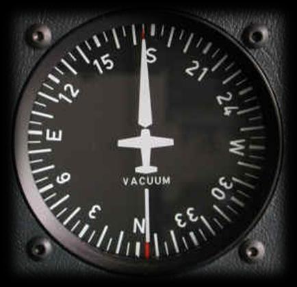


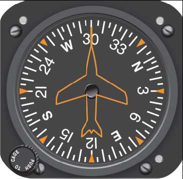
4 Vacuum Systems Components: Pumps Relief Valves Vacuum Manifold Vacuum Air Filter Suction Gauge Gyro instruments: Attitude Indicator Heading Indicator

5 Advantages of Pneumatics Simple Reliable Light weight Safe (if properly maintained)

6 Pneumatics Use in Small Aircraft
 Not all aircraft have")
7 Pneumatic System Components Pneumatic systems in GA aircraft are pretty straightforward: Air Pump Vacuum Regulator Inlet Air Filter Overboard Vent Line Gauges: Attitude Indicator Heading Indicator System Indicators Suction Gauge Gyro Flag Annunciator Lights (AL) Not all aircraft have ALs

8 How Pneumatic Systems Works Filtered Air is pulled through system by vacuum pump Evacuated air passes through instrument case causes gyro to spin Spinning gyros provide rigidity in space for instrument references Air exhausts through Gyro Pressure Gauge exhaust port Gauge measures system pressure Failure Warning Systems

9 Pneumatic Air Filter Prevent system contamination Remove air particulates Clean air is essential to good operation

10 Pneumatic Pressure Regulator Prevents system over pressurization Insures proper calibration


11 Air Pump Heart of pneumatic system is pressure or vacuum air pump (Usually engine driven) Two basic types : Wet air pumps use engine oil to lubricate pump internally Dry air pumps - more common have graphite vanes inside pump casing - self-lubricate as pump rotates.

12 GA Aircraft Instrument Panel


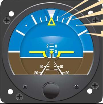
13 Attitude and Heading Indicators
 range Spotting pneumatic system failure early reduces chances of spatial")
14 Signs of Pneumatic System Failure Inaccurate/conflicting Instrument information Suction/pressure gauge indicates outside normal operating (green) range Spotting pneumatic system failure early reduces chances of spatial disorientation

15 Causes of Pneumatic System Failure Contamination: Solid particles in pneumatic system damage pump and plug valve openings Liquids from oil, water, or engine cleaning solvents A loose fitting or damaged hoses Worn out, misused, or incorrectly routed hoses Abrupt engine deceleration Sudden engine stoppage


16 To Avoid Spatial Disorientation Install a backup power supply for pneumatics Regularly check suction gauge in instrument scan Maintain proficiency in partial panel instrument flying Cover up or simulate loss of flight instruments Make timed turns Notify ATC, declare an Emergency In IMC seek and fly to VMC Ask ATC for no gyro vectors (and approach) Use a precision instrument approach, if available and favorable to your situation
17 Elements of a Basic Compressed Air Pneumatic System A. Air Compressor B. Check Valve C. Accumulator D. Directional Valve E. Actuator
18 A Compressor Pump that compresses air, raising air pressure to above ambient pressure for use in pneumatic systems
19 B Check valve One-way valve - allows pressurized air to enter the pneumatic system, but prevents backflow of air toward the Compressor when Compressor is stopped (prevent loss of pressure

20 C Accumulator Stores compressed air, Prevents surges in pressure Prevents constant Compressor operation ( duty cycles of Compressor)

21 D Directional valve Controls pressurized air flow from Accumulator (source to user equipment via selected port Some valves are one way shut tight Some valves are two way, allowing free exhaust from the port not selected valves can be actuated manually or electrically
22 E Actuator Converts energy stored in compressed air into mechanical motion Example is a linear piston (piston limited to moving in two opposing directions) Other examples are alternate tools including: rotary actuators, air tools, expanding bladders, etc
 Emergency Brakes (some aircraft) Cabin Pressure (for pressurized")
23 Pneumatic uses in Aircraft Powers engine Suction System for Heading indicators Attitude indicators Actuates Landing Gear (some aircraft) Emergency Brakes (some aircraft) Cabin Pressure (for pressurized aircraft)

24 Pressure Pump Types Two basic types: wet and dry Wet air pumps use engine oil to lubricate inside of pump Dry Air pumps - more common - have graphite vanes inside pump housing which self-lubricate as vane rotates

25 Pressure Pumps Heart of Pneumatics System Power Aircraft Flight Instruments using: Positive-Pressure Pump Increases air pressure, or Vacuum (negative pressure) Pump Decreases air pressure Both are usually engine-gear driven air pumps Air pump draws air into the system through a filter Fast-moving stream of air passes over rotating vanes within heading and attitude indicator gyroscopes, causing the gyroscopes to rotate at about 10,000 RPM. Creating rigidity in space

26 Converts Energy into Motion Pneumatic Actuator
27 High Pressure Air Systems Operate wing flaps, brakes, and landing gear. Hydraulic or actuating systems also operate these units. Pneumatic system also powers autopilot and de-ice systems. Reminder - Pneumatics are similar to hydraulics, except pneumatics use air rather than fluid for the actuation of mechanical units. One disadvantage of pneumatics is the air is compressible, unlike fluid in hydraulics, so pressure variability can be a problem.
")
28 Pneumatic Safety Systems Pressure to blow down and lock down gear in event of normal gear extension (hydraulic) failure

29 Deicing Boot Installed on Wings and Control Surfaces Made of Thick Rubber Membrane Inflates with Compressed Air

30 Pneumatics in Flying Surfaces (Wings and Empenage) Up to 15,000 psi Pyrotechnic and mechanical activation Variable damping and rate deployment Pneumatic Wing and Tail Actuators

31 Air Brakes Reduce Speed During Landing Increase Drag Little Effect on Lift
32 Pneumatic systems Other uses Waveguide Pneumatic safety systems are component systems in many aircraft Waveguide Pressurization System Delivers dry nitrogen Prevents Arcing in Radar Waveguide Fully automated system Used in High Performance Aircraft - F16 and F15E
33 Definitions Pneumatic systems Compressed Air A vacuum system Advantages of Pneumatic Systems Light weight Safe Reliable Eco-friendly Small (can be) Unaffected by atmospheric changes Inexpensive components Pressure seals are usually problem free Forces transmitted are easy to manage (within acceptable PSI limits)


34 Bottom Line - Safety Basic Operation Recognize Eminent System Failure -Take action Signs of Failure - Gauges - Warning Systems - Aircraft handling

35 When everything else goes wrong! The most important pneumatic system for pilot survival!!!

36 Pneumatics Systems for Small Aircraft Mark Tison, Silvia Fresnedo and The THE END FLY SAFE!!
37 References s=ywvrw63vnu&sig=aykt1s2yocq689t9yg4nuhiudyw#ppa283,m
38 Pneumatics Pneumatics-Pertaining to or operated by air or gas Mcgraw Hill, 2 nd ed.,dictionary of Engineering Pneumatics are compressed air directed at auxillary functions;ie.de-icing equip.the basic composition of all compressed gas systems include a compressor pump (or vac),a resevoir tank(enables capacity storage on demand supply),a pressure regulator,directional proportional valves,hi press. Air lines,and end use component or tool.
39 Pneumatics cont. Pneumatics are used to operate systems & equipment from remote locations(ie. Inside wings,or external hatches)pneumatics are lightweight,compact,sturdy and easily maintained.the principle operation of an aircrafts speed indicator,turn ind.,&gyros to name a few are pneumatic controlled. My main theory of this paper is to point out the turbo-charger system as a themo-pneumatic,jet pro-impelled dual dynamic system.the induction air is ram fed to the intake via a compressor,and the waste exhaust is redirected to a turbine impeller on the reverse end of the compressors shaft;which combines the use of compressed hot & cold gases to overcome thinner air at increased altitude and speeds.that is also thermo-dynamics.the use of both ends of the compressor as forced air induction and forced heat exhaust through the turbine is the basis of jet propulsion-although actually a right angle rather than staight through as typical jet engine.now add the cabin pressure system using compressed air and constant pressure adjustable releif valve-and you get 8000 ft pressure at 24ooo ft.flying above the weather and riding favorable winds making good time.
40 Air Pump Functionality 1.The air pump draws air into the system through a filter 2. The fast-moving stream of air passes over the vanes within the heading and attitude indicator gyros, causing the gyroscopes to rotate at about 10,000 RPM 3.In many aircraft, the same air pump powers the autopilot and de-ice systems

41 System Failure Alerts Pneumatic System health can be determined by the indications on either the vacuum gauge or flags on the attitude indicator
42 Redundancy and the Aircraft Pneumatic System Redundancy in a pneumatic system can take a load of worry off your plate Many newer aircraft come with redundant systems, older aircraft usually do not Pilots who frequently fly in IMC or night VMC should consider system redundancy Redundancy comes in several forms: Electrically-powered backup attitude and heading indicators Air pump redundancy with an electric or engine driven pump Standby vacuum system that utilizes the pressure differential from the engine s intake manifold
43 Questions?
44 Compressor System
45 Typical Components Compressor pump Accumulator tank Check valve Directional valve Actuator Relief valve Pressure gauge

46 Vacuum System
47 Typical Components Air inlet filter Instruments Vacuum regulator Air pump Overboard vent line
48 Other Uses in Aviation Wing de-icing equipment Manufacturing / maintenance Power tools
49 Warning! The attitude indicator is the most important flight instrument; wing icing is potentially fatal. Good maintenance will generally ensure the pneumatic system will be reliable when you need it the most!
50 Pneumatic Systems Advantages: Less Weight. No fire hazard. A clean system (no fluid). No requirement to return air to a reservoir. Known as vacuum or pressure systems. Driven by two types of air pumps, wet and dry. Wet air pumps use engine oil to lubricate the pump, dry pumps have vanes inside the pump that self-lubricate as they rotate.

51 AIRCRAFT PNEUMATIC SYSTEMS Corey Hjalseth Ali Spriggs
52 Pneumatic System A.K.A. Vacuum System Only certain flight instruments are powered by the vacuum system. The vacuum pump is mounted on the rear of the engine. The air pump is engine driven. The pump draws in the air through a filter. The air moves over the gyros for the heading and attitude indicator. The air causes the gyroscopes to move at 10,000 RPM. The air goes out through the vacuum regulator. The air finishes its trip by passing through the air pump and overboard vent line.
53 PNEUMATIC SYSTEMS DIAGRAM
54 TYPES OF PUMPS There are two kinds of pumps. Wet and dry. Wet pumps use engine oil for lubrication. Dry air pumps are more common then wet. Dry pumps have graphite vanes which lubricate as they rotate. The pumps effectiveness is measured by a suction gauge on the instrument panel. These pumps power the Heading and Attitude Indicators.
Surface and Brakes Anti-Ice Systems
 Surface and Brakes Anti-Ice Systems WING DEICE DISTRIBUTOR VALVE TAIL DEICE R BLEED FAIL VDC FROM RIGHT ENGINE P3 PNEUMATIC AIR SHUTOFF VALVE N.O. R BK DEICE ON Ice and Rain Protection N.C. TO DOOR SEAL
Section 5 - Ice & Rain Protection
 Section 5-5.1 Ice Detection 5.2 Ice Protection 5.2 Control 5.2 Operation 5.3 Engine Inlet 5.3 Pitot 5.4 Operation 5.4 Stall Warning Vane 5.4 Operation 5.4 Windshield 5.5 Windshield Anti-Ice Diagram - High
TECHNICAL PAPER 1002 FT. WORTH, TEXAS REPORT X ORDER
 I. REFERENCE: 1 30 [1] Snow Engineering Co. Drawing 80504 Sheet 21, Hydraulic Schematic [2] Snow Engineering Co. Drawing 60445, Sheet 21 Control Logic Flow Chart [3] Snow Engineering Co. Drawing 80577,
ESCONDIDO FIRE DEPT TRAINING MANUAL Section DRIVER OPERATOR Page 1 of 13 Pumps and Accessory Equipment Revised
 DRIVER OPERATOR Page 1 of 13 PUMPS AND ACCESSORY EQUIPMENT Pumps are designed for many different purposes. In order to understand the proper application and operation of a pump in a given situation, firefighters
Hydraulic System (i.e. Brakes & Cowl Flaps)
") Hydraulic System (i.e. Brakes & Cowl Flaps) B-17 Technical Session for Flight Engineers 7/8/2017 (with post meeting revisions 7/9/2017) The B-17G (specifically our Texas Raiders, TR) has a hydraulic system
Hydraulic System (i.e. Brakes & Cowl Flaps) B-17 Technical Session for Flight Engineers 7/8/2017 (with post meeting revisions 7/9/2017) The B-17G (specifically our Texas Raiders, TR) has a hydraulic system
Instructor Training Manual. Chapter 6 HYDRAULICS & PNEUMATICS
 Instructor Training Manual Chapter 6 HYDRAULICS & PNEUMATICS Learning Objectives 1. The purpose of this chapter is to provide a basic introduction to the principles of hydraulics & pneumatics and their
AIRCRAFT GENERAL KNOWLEDGE (1) AIRFRAME/SYSTEMS/POWERPLANT
 AIRFRAME/SYSTEMS/POWERPLANT") 1 In flight, a cantilever wing of an airplane containing fuel undergoes vertical loads which produce a bending moment: A highest at the wing root B equal to the zero -fuel weight multiplied by the span
1 In flight, a cantilever wing of an airplane containing fuel undergoes vertical loads which produce a bending moment: A highest at the wing root B equal to the zero -fuel weight multiplied by the span
Pneumatic Air Conditioning System Citation, Citation I
 Pneumatic Air Conditioning System Citation, Citation I COCKPIT VENT FOOT WARMER OVERHEAD COCKPIT WINDSHIELD WEMAC OPTIMAL VENT OVERHEAD CONDITIONED AIR DUCTS BLOWER SIDE WINDOW UNDER FLOOR CONDITIONED
Chapter 6. Supercharging
 SHROFF S. R. ROTARY INSTITUTE OF CHEMICAL TECHNOLOGY (SRICT) DEPARTMENT OF MECHANICAL ENGINEERING. Chapter 6. Supercharging Subject: Internal Combustion Engine 1 Outline Chapter 6. Supercharging 6.1 Need
OPERATIONS MANUAL FTO SECTION : 06.04
 06.04.08. OO-WIK SECTION : 06.04 PARTENAVIA OO-WIK PAGE : 1 PRE ENTRY PITOT COVER - REMOVE SNOW / ICE CHECK AIRCRAFT NOSE INTO WIND AIRCRAFT WEIGHT & BALANCE WITHIN LIMITS EXTERNAL (COCKPIT FIRST) PARK
2. Turbocharger System
 INTAKE (INDUCTION) 2. Turbocharger System A: GENERAL The turbocharger system consists of a water-cooled turbocharger, air-cooled intercooler, wastegate control solenoid valve, etc. The turbine rotated
I) Clamping the work piece II) Drilling the work piece. III) Unclamping the work piece. 10
 Clamping the work piece II) Drilling the work piece. III) Unclamping the work piece. 10") Seventh Semester B.E. III IA Test, 2014 USN 1 P E M E PES INSTITUTE OF TECHNOLOGY (Bangalore South Campus) (Hosur Road, 1KM before Electronic City, Bangalore-560 100) Department of Mechanical Engineering
Seventh Semester B.E. III IA Test, 2014 USN 1 P E M E PES INSTITUTE OF TECHNOLOGY (Bangalore South Campus) (Hosur Road, 1KM before Electronic City, Bangalore-560 100) Department of Mechanical Engineering
ASSIGNMENT Chapter 4 AIRCRAFT ELECTRICAL SYSTEMS
 ASSIGNMENT Chapter 4 AIRCRAFT ELECTRICAL SYSTEMS 4-1. What are the two most common types of bulb bases? A. Single wire and single contact B. Doubled filament and index C. Single and double contact bayonet
AERONAUTICAL ENGINEERING
 AERONAUTICAL ENGINEERING SHIBIN MOHAMED Asst. Professor Dept. of Mechanical Engineering Al Ameen Engineering College Al- Ameen Engg. College 1 Aerodynamics-Basics These fundamental basics first must be
VACUUM PUMP. Please read the operating manual carefully before using.
 Operating Manual 231672 Please read the operating manual carefully before using. I. Pump components Oil Fill Cap Handle Inlet Fitting Exhaust Fitting Power Switch Sight Glass Fan Cover Die-Cast Aluminum
Turbo Tech 101 ( Basic )
") Turbo Tech 101 ( Basic ) How a Turbo System Works Engine power is proportional to the amount of air and fuel that can get into the cylinders. All things being equal, larger engines flow more air and as
Turbo Tech 101 ( Basic ) How a Turbo System Works Engine power is proportional to the amount of air and fuel that can get into the cylinders. All things being equal, larger engines flow more air and as
Shafer RV-Series Rotary Vane Valve Actuators Operating Valves in Critical Pipeline Applications
 Shafer RV-Series Rotary Vane Valve Actuators Operating Valves in Critical Pipeline Applications Applications Emerson Process Management Valve Automation is recognized worldwide for the reliability of its
LUBRICATION SYSTEM B-17 Technical Session for Flight Engineers 10/14/2017
 LUBRICATION SYSTEM B-17 Technical Session for Flight Engineers 10/14/2017 The Lubrication System, and most everything else, is described in B-17 MANUALS published by the Army. Note that these Manuals were
Introduction to Hydraulics. Gui Cavalcanti 4/17/2012
 Introduction to Hydraulics Gui Cavalcanti 4/17/2012 Definition Transmission of mechanical power via incompressible liquids Hydraulic Power = Flow X Pressure Pressure X Area = Force Flow / Area = Velocity
Simple Carburettor Fuel System for a Piston Engine. And how it works
 Simple Carburettor Fuel System for a Piston Engine And how it works Inlet Exhaust Tank PISTON ENGINE Carburettor Fuel System Filler Cap COCKPIT FUEL GAUGE E FUEL 1/2 F Filler Neck Tank Cavity FUEL LEVEL
Owners Manual. Table of Contents 3.1. INTRODUCTION AIRSPEEDS FOR EMERGENCY OPERATION OPERATIONAL CHECKLISTS 3
 EMERGENCY PROCEDURES Table of Contents 3.1. INTRODUCTION 2 3.2. AIRSPEEDS FOR EMERGENCY OPERATION 2 3.3. OPERATIONAL CHECKLISTS 3 3.3.1. ENGINE FAILURES 3. ENGINE FAILURE DURING TAKEOFF RUN 3. ENGINE FAILURE
CESSNA 182 TRAINING MANUAL. Trim Control Connections
 Trim Control Connections by D. Bruckert & O. Roud 2006 Page 36 Flaps The flaps are constructed basically the same as the ailerons with the exception of the balance weights and the addition of a formed
So how does a turbocharger get more air into the engine? Let us first look at the schematic below:
 How a Turbo System Works Engine power is proportional to the amount of air and fuel that can get into the cylinders. All things being equal, larger engines flow more air and as such will produce more power.
Reducing Landing Distance
 Reducing Landing Distance I've been wondering about thrust reversers, how many kinds are there and which are the most effective? I am having a debate as to whether airplane engines reverse, or does something
P0441-EVAP PURGE SYSTEM PERFO... P0441-EVAP PURGE SYSTEM PERFORMANCE
 P0441-EVAP PURGE SYSTEM PERFO... P0441-EVAP PURGE SYSTEM PERFORMANCE For a complete wiring diagram, refer to the Wiring Information. Theory of Operation EVAP SYSTEM COMPONENTS CALLOUT DESCRIPTION 1 Filter
Metrovick F2/4 Beryl. Turbo-Union RB199
 Turbo-Union RB199 Metrovick F2/4 Beryl Development of the F2, the first British axial flow turbo-jet, began in f 940. After initial flight trials in the tail of an Avro Lancaster, two F2s were installed
Cessna Citation XLS - Anti-Ice & De-Ice Systems
 GENERAL The airplane utilizes a combination of engine bleed air, electrical heating elements and pneumatic boots to accomplish anti-ice/deice functions. The anti-ice system consists of bleed air heated
Initial / Recurrent Ground Take-Home Self-Test: The Beechcraft 58 Baron Systems, Components and Procedures
 Initial / Recurrent Ground Take-Home Self-Test: The Beechcraft 58 Baron Systems, Components and Procedures Flight Express, Inc. This take-home self-test partially satisfies the recurrent ground training
CHITKARA UNIVERSITY. (LECTURE NOTES SERIES FOR DR. REDDY Labs BADDI) Er. Anoop Aggarwal (Associate Professor, Deptt. Of Mechanical Engineering)
 Er. Anoop Aggarwal (Associate Professor, Deptt. Of Mechanical Engineering)") BASIC HYDRAULICS (LECTURE NOTES SERIES FOR DR. REDDY Labs BADDI) Er. Anoop Aggarwal (Associate Professor, Deptt. Of Mechanical Engineering) CHITKARA UNIVERSITY Er. GAUTAM MALIK Fluid Power Machine Hydraulic
BASIC HYDRAULICS (LECTURE NOTES SERIES FOR DR. REDDY Labs BADDI) Er. Anoop Aggarwal (Associate Professor, Deptt. Of Mechanical Engineering) CHITKARA UNIVERSITY Er. GAUTAM MALIK Fluid Power Machine Hydraulic
DESCRIPTION AND OPERATION ICE DETECTION SYSTEM
 ICE DETECTION SYSTEM 2.23. ICE DETECTION SYSTEM The ice detection system consists of an ice detector located on the right side of the airplane nose and two ICE amber caution lighted pushbuttons on both
Accident Prevention Program
 Accident Prevention Program Part I ENGINE OPERATION FOR PILOTS by Teledyne Continental Motors SAFE ENGINE OPERATION INCLUDES: Proper Pre-Flight Use the correct amount and grade of aviation gasoline. Never
Lesson 5: Directional Control Valves
 : Directional Control Valves Basic Hydraulic Systems Hydraulic Fluids Hydraulic Tank Hydraulic Pumps and Motors Pressure Control Valves Directional Control Valves Flow Control Valves Cylinders : Directional
A/C compressors: extending their service life
 FEATURE A/C compressors: extending their service life What can we say about the A/C compressor? Believe it or not, it is one of the hardestworking components on the vehicle. Its toughest job is to generate
HPUs Hydraulic Power Units
 HPUs Hydraulic Power Units DESIGN PHILOSOPHY Shafer has been manufacturing hydraulic power units (HPUs) for over 40 years. The primary industries we serve are natural gas, oil and water. The majority of
Air Management System Components
 AIR M anagement Sys tem Air Management System Components Air Management System Features Series Sequential The series sequential turbocharger is a low pressure/high pressure design working in series with
SECTION II AIRPLANE AND SYSTEMS MODEL 750 HYDRAULIC
 HYDRAULIC The main hydraulic system is comprised of two independent systems; system A and system B. Hydraulic power is used to power the primary flight controls (rudder, elevators, ailerons, and roll spoilers),
AIRCRAFT GENERAL KNOWLEDGE (2) INSTRUMENTATION
 INSTRUMENTATION") 1 The purpose of the vibrating device of an altimeter is to: A reduce the effect of friction in the linkages B inform the crew of a failure of the instrument C allow damping of the measurement in the unit
1 The purpose of the vibrating device of an altimeter is to: A reduce the effect of friction in the linkages B inform the crew of a failure of the instrument C allow damping of the measurement in the unit
CLOSED CIRCUIT HYDROSTATIC TRANSMISSION
 Energy conservation and other advantages in Mobile Equipment Through CLOSED CIRCUIT HYDROSTATIC TRANSMISSION C. Ramakantha Murthy Technical Consultant Various features/advantages of HST Hydrostatic transmissions
STUDENT APPLICATION CHECKLIST
 DIPLOMA OF ENGINEERING TECHNOLOGY IN AEROPLANE MAINTENANCE Module 1 AQD10102 Technical Mathematics 1 Module 2 AJD 10103 Physics & Aerodynamics AKD 10203 Electrical Fundamentals 2 Module 4 AKD 20102 Electronic
To study about various types of braking system.
 To study about various types of braking system INTRODUCTION The system is purely mechanical means & is independent of the hydraulic system which controls the brake normally. A brake commonly referred to
RX Catch Can installation & PCV system for Turbo & remote mount supercharger systems
 RX Catch Can installation & PCV system for Turbo & remote mount supercharger systems The LS based motors have a PCV system that at best is pretty ineffective. This allows oil mist to enter the intake manifold
Section 6.1. Implement Circuit - General System. General: TF Configuration TB Configurations Implement Control Valve:
 Section 6.1 Implement Circuit - General System General: TF Configuration... 6.1.3 TB Configurations... 6.1.5 Implement Pump Breakdown... 6.1.6 Operational Description: General... 6.1.7 Compensator Control...
A pump is a machine used to move liquid through a piping system and to raise the pressure of the liquid.
 What is a pump A pump is a machine used to move liquid through a piping system and to raise the pressure of the liquid. Why increase a liquid s pressure? Static elevation a liquid s pressure must be increased
Proper Propane Pump Installation
 Spring 2014 Proper Propane Pump Installation If installed correctly, a propane pump can operate many years with few or no problems. So often shortcuts are taken. Practical thinking goes out the window
GACE Flying Club Aircraft Review Test 2018 N5312S & N5928E. Name: GACE #: Score: Checked by: CFI #:
 GACE Flying Club Aircraft Review Test 2018 N5312S & N5928E Name: GACE #: Score: Checked by: CFI #: Date: (The majority of these questions are for N5312S. All N5928E questions will be marked 28E) 1. What
AVANTI P180. Ground Handling
 AVANTI P180 Ground Handling Towing The airplane should be moved on the ground with the aid of the nosewheel towing bar provided with the airplane. The tow bar is designed to attach to the nose wheel axle.
FRL unit consist of Filterations, Regulators and Lubricator unit.
 4.1 AIR CONTROL 4.1.1 Fluid Conditioner FRL unit consist of Filterations, Regulators and Lubricator unit. It is also known as Air Service Unit. Primary function is to provide clean air at optimal pressure
Typical Fuel Systems - An Overview
 Typical Fuel Systems - An Overview Richard Skiba Skiba, R. (1999). Typical Fuel Systems An Overview, Pacific Flyer, March. Skiba, R. (2001). 'Typical Fuel Systems - An Overview'. Air Sport: The Home of
Content : 4.1 Brayton cycle-p.v. diagram and thermal efficiency. 4Marks Classification of gas turbines.
 Content : 4.1 Brayton cycle-p.v. diagram and thermal efficiency. 4Marks Classification of gas turbines. 4.2 Construction and working of gas turbines i) Open cycle ii) Closed cycle gas Turbines, P.V. and
(Phone) (Fax) ( ) (Web) airflowperformance.com
 (Fax) ( ) (Web) airflowperformance.com") Airflow Performance Inc. 111 AIRFLOW DRIVE SPARTANBURG, SC 29306 (Phone) 864-576-4512 (Fax) 864-576-0201 (E-mail) airflow2@bellsouth.net (Web) airflowperformance.com Rev 7-05 AIRFLOW PERFORMANCE INC. PURGE
Airflow Performance Inc. 111 AIRFLOW DRIVE SPARTANBURG, SC 29306 (Phone) 864-576-4512 (Fax) 864-576-0201 (E-mail) airflow2@bellsouth.net (Web) airflowperformance.com Rev 7-05 AIRFLOW PERFORMANCE INC. PURGE
FLASHCARDS AIRCRAFT. Courtesy of the Air Safety Institute, a Division of the AOPA Foundation, and made possible by AOPA Services Corporation.
 AIRCRAFT FLASHCARDS Courtesy of the Air Safety Institute, a Division of the AOPA Foundation, and made possible by AOPA Services Corporation. Knowing your aircraft well is essential to safe flying. These
Page 2. Pitot tube anti-ice. Windshield Anti-ice Components. Propeller Anti-ice Components. Wing boot anti-ice pneumatic components
 Ice & Rain Trainer Component Location Page 2 Pitot tube anti-ice Propeller Anti-ice Components Windshield Anti-ice Components Wing boot anti-ice pneumatic components Control and Indicating Components 110
LogSplitterPlans.Com
 Hydraulic Pump Basics LogSplitterPlans.Com Hydraulic Pump Purpose : Provide the Flow needed to transmit power from a prime mover to a hydraulic actuator. Hydraulic Pump Basics Types of Hydraulic Pumps
ELECTRICAL SYSTEMS AIAA TEAM 1 VT AIAA TEAM 1 1
 ELECTRICAL SYSTEMS AIAA TEAM 1 VT AIAA TEAM 1 1 Electrical Systems in Aircraft Avionics Hydraulics Environmentalcontrol Lighting Subsystems VT AIAA TEAM 1 2 Electrical System Composition Batteries Alternators/Generators
Bombardier Challenger Auxiliary Power Unit
 GENERAL A Honeywell 36 150(CL) constant-speed gas turbine auxiliary power unit (APU) is installed within a fire-resistant compartment in the aft equipment bay. The APU drives a generator, providing AC
Syslog Technologies Innovative Thoughts
 AUTOMATIC PNEUMATIC WATER PUMPING SYSTEM SYNOPSIS The aim of the project is pneumatic operated water pumping system. Radial plunger Pneumatic Water pumping system are reciprocating pump in which the piston
Induction, Cooling, & Exhaust. Aviation Maintenance Technology 111 B B
 Induction, Cooling, & Exhaust Aviation Maintenance Technology 111 B - 112 B Unliscensed copyrighted material - W. North 1998 Unliscensed copyrighted material - W. North 1998 Induction = those locations
Interior Pre Flight Documents: Check Control Wheel Lock: Remove Flight Controls: Check Instruments: Check for Damage Switches: Verify All Off Master
 Interior Pre Flight Documents: Check Control Wheel Lock: Remove Flight Controls: Check Instruments: Check for Damage Switches: Verify All Off Master Switch ALT/BAT: On Fuel Gauge: Check Quantity Flaps:
This information covers the design and function of the intake and exhaust systems for the Volvo D16F engine.
 Volvo Trucks North America Greensboro, NC USA Intake and Exhaust System DService Bulletin Trucks Date Group No. Page 2.2007 250 35 1(6) Intake and Exhaust System Design and Function D16F W2005773 This
CDI Revision Notes Term 1 ( ) Grade 12 Advanced Unit 2 Mechanical Systems
 Grade 12 Advanced Unit 2 Mechanical Systems") CDI Revision Notes Term 1 (2017 2018) Grade 12 Advanced Unit 2 Mechanical Systems STUDENT INSTRUCTIONS Student must attempt all questions. For this examination, you must have: (a) An ink pen blue. (b)
CDI Revision Notes Term 1 (2017 2018) Grade 12 Advanced Unit 2 Mechanical Systems STUDENT INSTRUCTIONS Student must attempt all questions. For this examination, you must have: (a) An ink pen blue. (b)
CH.4 Basic Components of Hydraulic and Pneumatic System/16 M HAP/17522/AE5G
 Content : 4.1 Hydraulic and Pneumatic actuators. 10 Marks Hydraulic Actuators - Hydraulic cylinders (single, double acting and telescopic) construction and working, Hydraulic motors (gear and piston type)
JODEL D.112 INFORMATION MANUAL C-FVOF
 JODEL D.112 INFORMATION MANUAL C-FVOF Table of Contents I General Description...4 Dimensions:...4 Powertrain:...4 Landing gear:...4 Control travel:...4 II Limitations...5 Speed limits:...5 Airpeed indicator
Aero Engines. Review Oil & Fuel
 Aero Engines 9.02 Oil & Fuel References: FTGU pages 57-61 Review 1. What are the 4 strokes in a complete cycle? 2. Name 3 types of combustion engine. 3. List a few advantages and/or disadvantages to each
BONANZA 35 SERIES SHOP MANUAL. The time periods for inspections noted in this manual are based on average usage and average environmental conditions.
 200200200 OVERHAUL AND REPLACEMENT SCHEDULE The first overhaul or replacement must be performed not later than the recommended period. The condition of the item at the end of the first period can be used
Models
 Models 15300 15301 15500 15501 SAFETY PRECAUTIONS WARNING! To prevent personal injury, Wear goggles when working with refrigerants. Contact with refrigerants may cause injury. Incorrect use or connections
High CATALOG. Efficiency. Pilot Operated Safety Valves Series 810 Pop Action Series 820 Modulate Action. The-Safety-Valve.com
 High Efficiency Pilot Operated Safety Valves Series 10 Pop Action Series 20 Modulate Action CATALOG The-Safety-Valve.com Valve finder How to find the right product group High operating to set pressure
Chapter 3: Aircraft Construction
 Chapter 3: Aircraft Construction p. 1-3 1. Aircraft Design, Certification, and Airworthiness 1.1. Replace the letters A, B, C, and D by the appropriate name of aircraft component A: B: C: D: E: 1.2. What
FTM-L SERIES SINGLE OR TWIN DIRECT STEAM MIXER KETTLE COMPLETE WITH HYDRAULIC POWER TILT BRIDGE PARTS AND SERVICE MANUAL
 FTM-L SERIES SINGLE OR TWIN DIRECT STEAM MIXER KETTLE COMPLETE WITH HYDRAULIC POWER TILT BRIDGE PARTS AND SERVICE MANUAL EFFECTIVE SEPTEMBER 19, 2014 Superseding All Previous Parts Lists. The Company reserves
AIRCRAFT GENERAL KNOWLEDGE (2) INSTRUMENTATION
 INSTRUMENTATION") 1 The purpose of the vibrating device of an altimeter is to: A reduce the effect of friction in the linkages B inform the crew of a failure of the instrument C allow damping of the measurement in the unit
1 The purpose of the vibrating device of an altimeter is to: A reduce the effect of friction in the linkages B inform the crew of a failure of the instrument C allow damping of the measurement in the unit
TECNAM P2004 BRAVO N128LS
 TECNAM P2004 BRAVO N128LS GENERAL INFORMATION NORMAL PROCEDURES TIME SENSITIVE EMERGENCY TECNAM P2004 BRAVO CHECKLIST [FLIGHT PLAN DESIGNATION IS BRAV ] EMERGENCY CONTACT The following are First Landings'
 www.thecarproblems.com/automotive-service-centre How You Diagnose Your Car Problems And Save Money A Quick Look At An Automotive Service Turbo For Your Car - Benefits, Precautions And Just How Does It
CHAPTER 7 ABNORMAL FLOWS AND CHECKLISTS TABLE OF CONTENTS
 CHAPTER 7 ABNORMAL FLOWS AND CHECKLISTS TABLE OF CONTENTS ELECTRICAL FAULTS...3 Alternator Failure / Low Voltage...3 INSTRUMENTS...7 Low vacuum indication / vacuum failure...7 Erroneous airspeed / altitude
Review and Proposal of Exhaust gas operated air brake system for automobile
 Review and Proposal of Exhaust gas operated air brake system for automobile Shriram Pawar 1, Praful Rote 2, Pathan Sahil, Mohd Sayed 4 1 BE student Mechanical, SND COE & RC, YEOLA, Maharashtra,India 2
GENERAL The Honeywell model TFE731-40AR turbofan engine is a lightweight, two-spool, geared-stage, front-fan, jet engine.
 ENGINE GENERAL The Honeywell model TFE731-40AR turbofan engine is a lightweight, two-spool, geared-stage, front-fan, jet engine. The cross section of the engine is shown in Figure 7-71-1, page VII-71-3.
Definitions of Technical Terms
 Definitions of Technical Terms ABSOLUTE A measure having as it s zero point of base the complete absence of the entity being measured. ABSOLUTE PRESSURE A pressure scale with zero point at a perfect vacuum.
3. Fuel System FUEL SYSTEM FUEL INJECTION (FUEL SYSTEM) A: GENERAL. FU(STi)-7
 A: GENERAL. FU(STi)-7") W1860BE.book Page 7 Tuesday, January 28, 2003 11:01 PM 3. Fuel System A: GENERAL The fuel pressurized by the fuel tank inside pump is delivered to each fuel injector by way of the fuel pipe and fuel filter.
W1860BE.book Page 7 Tuesday, January 28, 2003 11:01 PM 3. Fuel System A: GENERAL The fuel pressurized by the fuel tank inside pump is delivered to each fuel injector by way of the fuel pipe and fuel filter.
Internal Combustion Engines
 Internal Combustion Engines The internal combustion engine is an engine in which the burning of a fuel occurs in a confined space called a combustion chamber. This exothermic reaction of a fuel with an
Test Which component has the highest Energy Density? A. Accumulator. B. Battery. C. Capacitor. D. Spring.
 Test 1 1. Which statement is True? A. Pneumatic systems are more suitable than hydraulic systems to drive powerful machines. B. Mechanical systems transfer energy for longer distances than hydraulic systems.
BRAKE SYSTEM, HYDRAULICALLY ACTUATED - 631G TRACTOR Cat Tractors with standard shoe/drum brakes
 BRAKE SYSTEM, HYDRAULICALLY ACTUATED - 631G TRACTOR 194139 631 Cat Tractors with standard shoe/drum brakes Kress Corporation modifies the Caterpillar tractor air actuated shoe brake system to a hydraulically
DCS L-39 ALBATROS REAL PILOT START-UP, TAXI AND TAKEOFF CHECKLISTS V 1.0 PREPARED BY LINO_GERMANY
 DCS L-39 ALBATROS REAL PILOT START-UP, TAXI AND TAKEOFF CHECKLISTS V 1.0 PREPARED BY LINO_GERMANY T.O. 1T-L39C-1.0 P1 INTRODUCTIONS A. CHECKLISTS This compilation contains amplified normal and (hopefully
1 of 7 12/18/2016 9:15 PM
 1 of 7 12/18/2016 9:15 PM P0456-EVAP SYSTEM SMALL LEAK Special Tools: For a complete wiring diagram, refer to the Wiring Information. 2 of 7 12/18/2016 9:15 PM Theory of Operation 3 of 7 12/18/2016 9:15
HYVAC PRODUCTS, INC. Capture Filters for Vacuum Pump Exhaust
 Capture Filters for Vacuum Pump Exhaust Exhaust filters are often used on oil sealed rotary vane vacuum pumps. The main reason to use an exhaust filter is to eliminate or minimize oil mist that can often
Cathay Pacific I Can Fly Programme General Aviation Knowledge. Aerodynamics
 Aerodynamics 1. Definition: Aerodynamics is the science of air flow and the motion of aircraft through the air. 2. In a level flight, the 'weight' and 'lift' of the aircraft respectively pulls and holds
LIQUID MEASUREMENT STATION DESIGN Class No
 LIQUID MEASUREMENT STATION DESIGN Class No. 2230.1 Michael Frey Systems Sales Manager Daniel Measurement & Control, Inc. 5650 Brittmoore Rd. Houston, Texas 77041 INTRODUCTION The industry continues to
TECNAM P92 EAGLET N615TA TECNAM P92 EAGLET CHECKLIST [FLIGHT PLAN DESIGNATION IS ECHO ]
![TECNAM P92 EAGLET N615TA TECNAM P92 EAGLET CHECKLIST [FLIGHT PLAN DESIGNATION IS ECHO ]](/thumbs/86/93080937.jpg "TECNAM P92 EAGLET N615TA TECNAM P92 EAGLET CHECKLIST [FLIGHT PLAN DESIGNATION IS ECHO ]") TECNAM P92 EAGLET CHECKLIST [FLIGHT PLAN DESIGNATION IS ECHO ] EMERGENCY CONTACT The following are First Landings' emergency contact telephone numbers. We ask that you call the numbers in the order listed.
TECNAM P92 EAGLET CHECKLIST [FLIGHT PLAN DESIGNATION IS ECHO ] EMERGENCY CONTACT The following are First Landings' emergency contact telephone numbers. We ask that you call the numbers in the order listed.
VALVE TIMING DIAGRAM FOR SI ENGINE VALVE TIMING DIAGRAM FOR CI ENGINE
 VALVE TIMING DIAGRAM FOR SI ENGINE VALVE TIMING DIAGRAM FOR CI ENGINE Page 1 of 13 EFFECT OF VALVE TIMING DIAGRAM ON VOLUMETRIC EFFICIENCY: Qu. 1:Why Inlet valve is closed after the Bottom Dead Centre
Laboratory Lubricated Vane Vacuum System with Premium NFPA Controls
 Laboratory Lubricated Vane Vacuum with Premium NFPA Controls Specification General The Powerex laboratory vacuum system is designed to create a suction system to remove unwanted fluids or gases from laboratory
Lucinda Handwriting & Arial Black 11, 16, 18 34
 Access and inspection holes are provided in the cabin floor for servicing cables, hydraulic lines, landing gear and gasoline tank. Additional access holes are provided on the exterior at the boom for servicing
PILOT S GUIDE. for the XXX Series Electric Attitude Indicator with Battery Backup
 PILOT S GUIDE for the 4300-XXX Series Electric Attitude Indicator with Battery Backup Mid-Continent Instruments and Avionics 9400 E. 34 th Street N., Wichita, KS 67226 USA Phone 316-630-0101 Fax 316-630-0723
/.4=111. Lubrication Systems 6-23
 Lubrication Systems 6-23 The transducer is designed so that it sends a corrected oil pressure (fluid pressure minus vent "air" pressure) to the cockpit gauge. This design is used because vent pressure
Marine Engineering Exam Resource Review of Hydraulics
 1. What is Pascal s law? Pressure confined on a confined fluid will transmit the pressure in all directions and act with equal force on all areas at right angles. 2. How does the law pertain to hydraulics?
Name Date. True-False. Multiple Choice
 Name Date True-False T F 1. Oil film thickness increases with an increase in oil temperature. T F 2. Displacement is the volume that a piston displaces in an engine when it travels from top dead center
Powertrain Efficiency Technologies. Turbochargers
 Powertrain Efficiency Technologies Turbochargers Turbochargers increasingly are being used by automakers to make it possible to use downsized gasoline engines that consume less fuel but still deliver the
TURBOCHARGER Toyota Celica DESCRIPTION OPERATION TURBOCHARGING SYSTEMS All Models
 TURBOCHARGER 1988 Toyota Celica 1988 TURBOCHARGING SYSTEMS All Models DESCRIPTION Most models use a water-cooled turbocharger, mounted directly to the exhaust manifold with a wastegate assembly attached
canadair chzflleriqer OPERATING MANUAL PSP 601A-6 SECTION 5 AUXILIARY POWER UNIT (APU)
") OPERATING MANUAL. AUXILIARY POWER UNIT (APU) 1.. 3. 4. 5. 6. GENERAL APU CONTROL START SYSTEM SHUTDOWN BLEED AIR SYSTEM OIL SYSTEM TABLE OF CONTENTS Page 1 3 3 Figure Number LIST OF ILLUSTRATIONS Title
OPERATING MANUAL. AUXILIARY POWER UNIT (APU) 1.. 3. 4. 5. 6. GENERAL APU CONTROL START SYSTEM SHUTDOWN BLEED AIR SYSTEM OIL SYSTEM TABLE OF CONTENTS Page 1 3 3 Figure Number LIST OF ILLUSTRATIONS Title
AUTOGAS 150 SERIES PUMPS INSTALLATION GUIDELINES FOR UNDERGROUND TANK APPLICATIONS
 Application Bulletin A Unit of IDEX Corporation No. 13 June 21 AUTOGAS 1 SERIES PUMPS INSTALLATION GUIDELINES FOR UNDERGROUND TANK APPLICATIONS CORKEN, INC. A Unit of IDEX Corporation P.O. Box 12338, Oklahoma
UNIT IV INTERNAL COMBUSTION ENGINES
 UNIT IV INTERNAL COMBUSTION ENGINES Objectives After the completion of this chapter, Students 1. To know the different parts of IC engines and their functions. 2. To understand the working principle of
Design and Fabrication of Sequencing Circuit with Single Double Acting Cylinder
 Design and Fabrication of Sequencing Circuit with Single Double Acting Cylinder V.G.Vijaya Department of Mechatronics Engineering, Bharath University, Chennai 600073, India ABSTRACT: This project deals
Supercharging INDUCTION. Its purpose is to increase the mass of the air/fuel charge going into the engine for each revolution.
 Supercharging INDUCTION Its purpose is to increase the mass of the air/fuel charge going into the engine for each revolution. Most supercharged engines also have constant speed propellers They are designed
V - Speeds. RV-10 V fe Flaps Speeds Trail (0 deg) Half (15 deg) Full (30 deg) 122 kias 96 kias. 80 kias
 Half (15 deg) Full (30 deg) 122 kias 96 kias. 80 kias") RV-10 Check List V - Speeds RV-10 V fe Flaps Speeds Trail (0 deg) Half (15 deg) Full (30 deg) 122 kias 96 kias 87 kias V s1 Stall (Flap Up) 60 kias V s0 Stall (Flap 40 deg) 55 kias Best Glide 80 kias V
RV-10 Check List V - Speeds RV-10 V fe Flaps Speeds Trail (0 deg) Half (15 deg) Full (30 deg) 122 kias 96 kias 87 kias V s1 Stall (Flap Up) 60 kias V s0 Stall (Flap 40 deg) 55 kias Best Glide 80 kias V