/.4=111. Lubrication Systems 6-23
|
|
|
- Jonah Miller
- 5 years ago
- Views:
Transcription


1 Lubrication Systems 6-23 The transducer is designed so that it sends a corrected oil pressure (fluid pressure minus vent "air" pressure) to the cockpit gauge. This design is used because vent pressure opposes oil flow at the oil jets, and the operator needs to know the flow condition in terms of corrected oil pressure. The vent system is explained in detail later in this chapter. The oil pressure indicating system is explained in detail in Chapter XII. Note that in this system, the entire oil supply circulates approximately three times per minute. This is typical of most gas turbine engines. The CJ61 lubrication system is considered a hot tank system because the oil cooler is located in the pressure subsystem and the oil is scavenged (hot) back to the oil tank. b. System Components 1) Oil Cooler The oil cooler's main function is to maintain a specific oil temperature under differing oil heat conditions which occur at varying engine speeds. The oil cooler shown in Figure 6-28 is a liquid-to-liquid heat exchanger. It contains numerous soda-straw type passageways for fuel flow on its way to the combustor while the oil circulates around the straws. This allows an exchange of heat to occur between the fuel and the oil. This fuel-cooled oil cooler contains a combination differential pressure bypass valve and thermostatic bypass valve at the cooler inlet. When the oil is cold, the valve is open, allowing oil to take the path of least POPPET /.4=111 SPRING SYSTEM RELIEF VALVE TO ENGINE ANTI-STATIC LEAK CHECK VALVE (2-3 PSID) #9'.'" Mrli, An> or#m14 wire. FROM RESERVOIR PUMP Fig. 6-26A In-line type antistatic-leak check valve. Fig. 6-26B In oil-filter type antistatic-leak check valve.


2 6-24 Aircraft Gas Turbine Powerplants 111 CD ILI Z 2 D Lu CTJ ZW U. < LLI tr h- U) Z > ILI 2 Ui > Z OW ox w 3 U.1 < < LU cr o I- 2' 2 ec (t) 9 4. > up cc u. 4 w t <1.11-1,.. Ili O. --1 T. -I a: co w 2 2 <, cc IJJ will O. w cc I- co > >..1 CD P > < -i (n o> P ce U- 3 a Lu a. 2


3 Lubrication Systems 6-25 resistance, bypassing the cooling chamber and flowing directly to the system (Figure 6-28B). When the oil heats up, the thermo-valve expands to close, forcing the oil to flow through the cooler. If a restriction occurs from cooler clogging, pressure buildup off-seats the bypass valve and oil flows uncooled, at a slightly reduced pressure, to the system. The thermostatic valve contains a bi-metallic spring, typically constructed of iron/nickel alloy and brass, which, because of the different coefficient of expansion, produces movement with loss or gain of heat (Figure 6-28C). A typical oil cooler operational schedule might be as follows: Oil cooler thermostatic valve starts to close at 165 F, and is fully closed at 185 F, with normal engine oil temperature stabiliing at 21 F. From this point, the cooler capacity for fuel flow and oil flow regulate the operational oil temperature rather than the thermo-valve. As the throttle is advanced for the engine to create more power, and therefore more heat for the oil to absorb, the fuel flow through the cooler increases and absorbs this heat. The maximum continuous oil temperature in this system would be 21 F. If the temperature reached a value over 21 Fbut under 23 F, the red line, the engine would have to be operated at reduced power at the (A) THERMOSTAT TEMPERATURE DIFFERENTIAL PRESSURE AND THERMOSTATIC BY-PASS VALVE (SHOWN I? COLD MODE) (C) TEMPERATURE THERMOSTAT (IN HOT MODE) BY-PASS SPRING L PRESSURE BY-PASS VALVE Fig. 6-28A Oil cooler exterior. Fig 6-28B Thermo-valve in transit with oil both cooling and bypassing. Fig. 6-28C Thermo-valve closed when oil is hot.
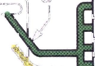
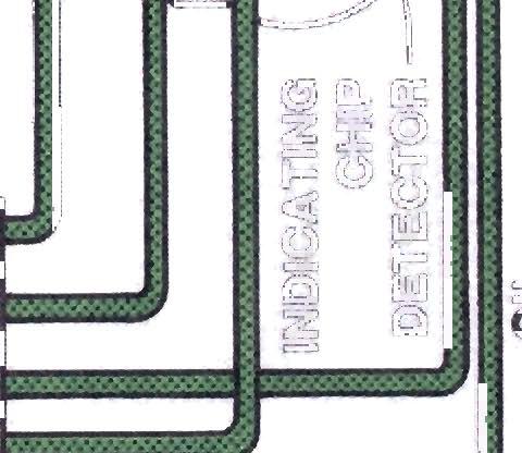
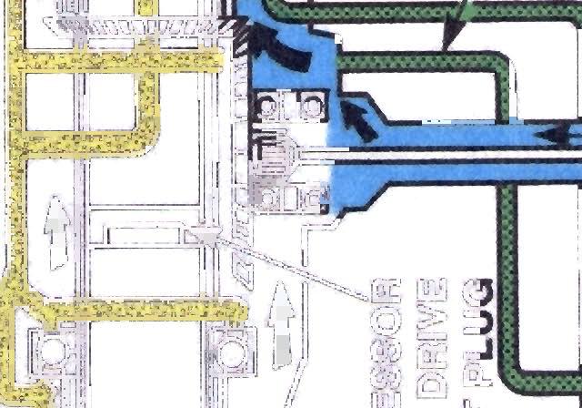
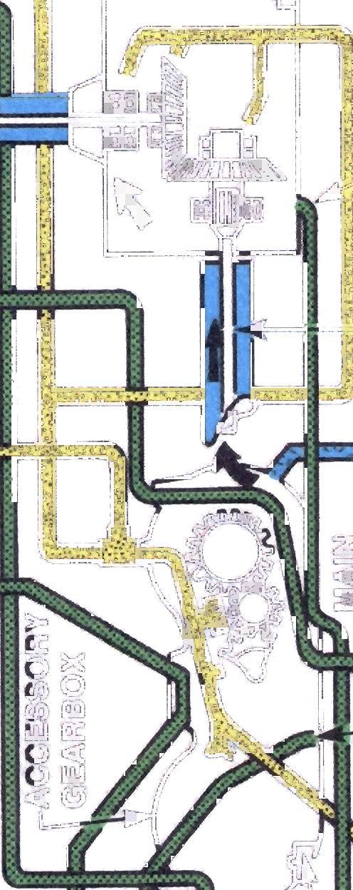
4 6-26 Aircraft Gas Turbine Pow rplants discretion of the pilot. Once an oil temperature of 23 F is reached, the engine would have to be shut down. The purpose of the thermostatic valve is to quickly bypass oil to the lube points on a cold start. It is not uncommon, however, to see an oil cooler without a thermostatic device if oil can be distributed rapidly enough for quick lubrication when the oil is cold. One of the checks on an oil cooler is to see a momentary oil temperature rise on engine deceleration, and drop on acceleration as a function of fuel flow. From this, the operator can conclude that the thermo-valve is not stuck in a transient position and is not bypassing. The fuel-oil cooler is used on most engines and often on larger engines, in combination with an air-oil cooler. The air-oil cooler is also in popular use. The air-oil cooler and thermostatic valve arrangement is quite similar in principle and design to the fuel-oil coolers shown, but the heat exchanger section looks similar to the small radiator type cooler used on reciprocating engines (Figure 6-33). 2) Oil Jets (Figure 6-29A) Oil jets, or noles, as they are sometimes called, are located at the various places within the engine that need to be lubricated. Oil jets are the terminating point of the pressure subsystem. They deliver either an atomied spray or a fluid stream of oil to bearings, oil seals, gears, and other parts. The fluid stream method is the most common, especially when high loads are present. In most cases this stream of oil is directed onto the bearing surfaces from what is termed a Direct Lubrication Oil Jet (Figure 6-29B). Another less common method is called a Mist and Vapor Lubrication Oil Jet, where the oil stream (sometimes an air-oil stream) is aimed at a splash pan and slinger ring device. This allows for a wider area of lubrication from a single oil jet and is utilied in some larger engines (Figure 6-29C). A newer type of oil jet coming into use is called "under-race lubrication", in which oil is routed through rotor shafts and bearing journals, then fed through slots acting as oil jets in the bearing inner races. Manufacturer's information indicates that they are achieving superior cooling when comparing traditional spray-jet lubrication with this method. Over time, a restriction to flow may occur at the calibrated orifice of the oil jet. An accumulation of carbon (called coking) takes place due to residual engine heat acting on oil coated metal parts. This condition results faster if the prescribed cooling down period prior to engine shutdown is ignored. Oil jets can be checked for sie and cleanliness with a drill pin or the shank end of a new numbered drill bit. It is very important that the drill shank be free from any nicks or burrs. Another method of checking for restrictions to flow is the smoke check. Smoke or shop air is directe oil nole inlet port and a check is made of the rate through the orifice. A comparison is usually known good or new oil jet. A flow tester is also available in most larg facilities. This device can measure rate accurately, in gallons per minute, with the oil jet in the engine. On some engines, bearing flow c part of the 1-hour inspection, or similar i requirements. 3) Last Chance Filters Quite often, last chance filters are installed i to prevent plugging of the oil jets. Observe 6-29A the last chance filters. Because of thei location within the engine, last chance fi accessible for cleaning only during engine ove prevent engine damage from clogged last chanc or plugged oil jets, the main filters are ins frequent intervals by ground personnel. Flow detect early signs of filter blockage is also acco at periodic intervals. into the ischarge ade to a r repair f flow installed ecks are spection oil lines 1 Figure remote ters are haul. To screens ected at sting to plished 2. Scavenge Subsystem (C161) (Figure 6-27) The scavenge subsystem removes oil from th- bearing compartments and gearboxes by suction rom the lubrication pump scavenge return elements (1 o 5). All five scavenge elements route oil to one return li e, which enters the dwell chamber in the oil tank. T e dwell chamber acts as an air--oil separator. The total eturn oil capacity is nine gallons per minute. The entrain4d air that accumulates in the oil increases oil vol me and necessitates the use of a much higher capacity scavenge subsystem than the pressure subsystem. a. Chip Detectors Many scavenge systems contain permane magnet chip detectors which attract and hold ferr s metal particles (Figure 6-3) which would otherwise circulate back to the oil tank and the engine pressure subsystem, possibly causing wear or damage. Chip detectors are a point of frequent inspection to detect early signs of main bearing failure. As a general rule, the presence of small fuy particles or gray metallic paste is considered satisfactory and the result of normal wear. Metallic chips or flakbs are an indication of serious internal wear or malfunction. Refer to Figures 6-3A and 6-3B. Figure 6-33 (insert) shows an indicting-type magnetic chip detector. It has a warning circuit feature. When debris bridges the gap between the magnetic positive electrode in the center and the ground electrode (shell), a warning light is activated in the cockpit. When the light illuminates, the flight crew will take whatever action is warranted, such as in-flight shutdown, continued operation at flight idle, or continued operation at normal cruise, depending on the other engine in truments readings.
5 Lubrication Systems 6-27 b. Pulsed Chip Detector System A newer type of chip detector is the Electric Pulsed Chip Detector, which can discriminate between small wear-metal particles, both ferrous and non-ferrous, considered non-failure related, and larger particles, which can be an indication of bearing failure, gearbox failure, or other potentially serious engine malfunction (Figure 6-3C). The Pulsed Chip Detector looks like the Indicating Chip Detector at the gap-end, but its electrical circuit contains a pulsing mechanism which is powered by the aircraft 28 VDC bus. The pulsed detector is designed with either one or two operating modes: Manual only or manual and automatic. In the manual mode, each time the gap is sufficiently bridged, regardless of the particle sie, the warning light will illuminate in the cockpit. The operator will then initiate the pulse; electrical energy will discharge across the gap-end in an attempt to separate the debris from the hot center electrode. This procedure is called burn-off. If the light goes out and stays out, the operator will consider the bridging a result of a non-failure related cause. If the light does not go out, or repeatedly comes on after being cleared, the operator will take appropriate action, such as reducing engine power or shutting down the engine. In the automatic mode, if the gap is bridged by small debris, a pulse of electrical energy discharges across the gap. The resulting burn-off prevents a cockpit warning light from illuminating by opening the circuit before a time-delay relay in the circuit activates to complete the current path to ground. If the debris is a large particle, it will remain in place after the burn-off cycle is completed and a warning light will illuminate in the cockpit when the time delay relay closes. LAST CHANCE FILTER IN LAST CHANCE FILTER CARBON SEAL JETS LABYRINTH AIR- SEAL,:iCOMPRESSOR SHAFT CARBON SEALS GEARBOX DRIVE SHAFT DRAIN DETAIL OF NOZZLE OPERATION 7SSMSS:ZZT JET Fig. 6-29A Location of main bearing oil jets and filters. Fig. 6-29B Direct lubrication oil jet. Fig. 6-29C Mist and vapor oil jet.
LUBRICATION SYSTEM B-17 Technical Session for Flight Engineers 10/14/2017
 LUBRICATION SYSTEM B-17 Technical Session for Flight Engineers 10/14/2017 The Lubrication System, and most everything else, is described in B-17 MANUALS published by the Army. Note that these Manuals were
General Issues of Line Leak Detection
 Quality Petroleum Equipment Solutions for Over 20 Years ARM-4073 AST-4010 AST-4012 CFOSI FST-200 ISM-4080 ISM-4081 ISM-4080 MC LD-2000 LD-2000\E LD-2200 LD-2200\75 LD-3000 LD-3000\E LD-3000\FL LDT-890
GENERAL The Honeywell model TFE731-40AR turbofan engine is a lightweight, two-spool, geared-stage, front-fan, jet engine.
 ENGINE GENERAL The Honeywell model TFE731-40AR turbofan engine is a lightweight, two-spool, geared-stage, front-fan, jet engine. The cross section of the engine is shown in Figure 7-71-1, page VII-71-3.
CHAPTER 5 SINGLE-ROTOR POWER TRAIN SYSTEM MAIN DRIVE SHAFT FM 1-514
 CHAPTER 5 SINGLE-ROTOR POWER TRAIN SYSTEM A typical single-rotor power tram system (Figure 5-1) consists of a main transmission (main gearbox), a main drive shaft, and a series of tail rotor drive shafts
COOLING SYSTEM - V8. Cooling system component layout DESCRIPTION AND OPERATION
 Cooling system component layout 26-2-2 DESCRIPTION AND OPERATION 1 Heater matrix 2 Heater return hose 3 Heater inlet hose 4 Heater inlet pipe 5 Throttle housing 6 Connecting hose 7 Throttle housing inlet
Module 7: Cooling System Components
 Â ÂÂ Â Basic Cooling System Components Radiators Common Types of Radiators Coolant Hoses Water Pumps Centrifugal Force Types of Drives for Water Pumps Types of Drive Belts Basic Cooling System Components
 Â  Basic Cooling System Components Radiators Common Types of Radiators Coolant Hoses Water Pumps Centrifugal Force Types of Drives for Water Pumps Types of Drive Belts Basic Cooling System Components
HYDRAULIC SYSTEM, ISL-07
 SECTION 09-304.295 09-304.295/ 1 GENERAL DESCRIPTION 7 1 This system uses hydraulic power to operate a fan that forces outside air into the radiator located on the left-hand side at the rear of the bus.
AN EXPLANATION OF CIRCUITS CARTER YH HORIZONTAL CLIMATIC CONTROL CARBURETER
 AN EXPLANATION OF CIRCUITS CARTER YH HORIZONTAL CLIMATIC CONTROL CARBURETER The Carter Model YH carbureter may be compared with a Carter YF downdraft carbureter with the circuits rearranged to operate
Section 13 - E. 1 of 18. Engine Systems
 Engine Systems 1 of 18 ENGINE FUEL SYSTEM Introduction The fuel system uses electronic, hydraulic and mechanical functions to regulate the power and adapt it to the requirements at any one time. Air pressure
CHAPTER 12 SERVICING. Section Title Page
 CHAPTER 12 SERVICING Section Title Page 12-10 Main Rotor Gearbox.................................. 12.1 12-11 Servicing................................. 12.1 12-12 Filter Replacement...........................
Module 13: Mechanical Fuel Injection Diagnosis and Repair
 Terms and Definitions Parts of Injection Nozzles Types of Nozzle Valves Operation of an Injection Nozzle Fuel Flow Through the Unit Injector Optional Features on Fuel Injection Pumps Main Parts of a Distributor-Type
Internal Combustion Engines
 Internal Combustion Engines The internal combustion engine is an engine in which the burning of a fuel occurs in a confined space called a combustion chamber. This exothermic reaction of a fuel with an
Cla-Val. Service Training Manual. Simple solutions plus learning with a purpose
 Cla-Val Service Training Manual Simple solutions plus learning with a purpose 5 Application Series Section General Identify What Valve You Have 5-1 Rate of Flow 40 Series 5-2 Pressure Relief 50 Series
TC Series Cooling Systems
 TC Series Cooling Systems Table of Contents Table of Contents...1 List of Figures...1 Safety...2 Introduction...2 General Specifications...2 Types of Coolant...2 Routine Maintenance...2 Surge Tank Coolant
Lubrication & Cooling Systems
 Study Guide Chapter 14 Pages 393 432 44 Points 1. The life span of an engine depends largely upon its & systems. Lube & Cooling The American Petroleum Institute (API) rates oil service classification.
Turbo Tech 101 ( Basic )
") Turbo Tech 101 ( Basic ) How a Turbo System Works Engine power is proportional to the amount of air and fuel that can get into the cylinders. All things being equal, larger engines flow more air and as
Turbo Tech 101 ( Basic ) How a Turbo System Works Engine power is proportional to the amount of air and fuel that can get into the cylinders. All things being equal, larger engines flow more air and as
DESCRIPTION AND OPERATION
 Page 1 of 10 DESCRIPTION AND OPERATION AIR DELIVERY DESCRIPTION AND OPERATION The air delivery description and operation is divided into five areas: HVAC Control Components Air Speed Air Delivery Recirculation
Troubleshooting The Transmission Hydraulic System
 416B, 426B, 428B, 436B, & 438B BACKHOE LOADERS TRANSMISSION Testing And Adjusting Troubleshooting The Transmission Hydraulic System Make reference to the following warning and pressure tap locations for
TECHNICAL PAPER 1002 FT. WORTH, TEXAS REPORT X ORDER
 I. REFERENCE: 1 30 [1] Snow Engineering Co. Drawing 80504 Sheet 21, Hydraulic Schematic [2] Snow Engineering Co. Drawing 60445, Sheet 21 Control Logic Flow Chart [3] Snow Engineering Co. Drawing 80577,
SECTION HYDRAULIC SYSTEM
 09-304.06/ 1 SECTION 09-304.06 GENERAL DESCRIPTION 7 1 This system uses hydraulic power to operate a fan that forces outside air into the radiator located on the left-hand side at the rear of the bus.
So how does a turbocharger get more air into the engine? Let us first look at the schematic below:
 How a Turbo System Works Engine power is proportional to the amount of air and fuel that can get into the cylinders. All things being equal, larger engines flow more air and as such will produce more power.
Section of 14. Ice and Rain Protection
 Ice & Rain Protection 1 of 14 WINDSCREEN WIPERS General The aircraft is fitted with two windscreen wipers, one on each pilots side windscreen, which are controlled by a 3-position (FAST, SLOW and MANUAL)
Introduction. APU Location
 B737 NG APU Introduction The auxiliary power unit (APU) is a self contained gas turbine engine installed within a fireproof compartment located in the tail of the airplane. The APU supplies bleed air for
 Page 1 of 9 303-01C Engine 6.0L Diesel 2004 F-Super Duty 250-550/Excursion DESCRIPTION AND OPERATION Procedure revision date: 08/06/2003 Engine Printable View Engine Description The 6.0L diesel engine
Section 6.1. Implement Circuit - General System. General: TF Configuration TB Configurations Implement Control Valve:
 Section 6.1 Implement Circuit - General System General: TF Configuration... 6.1.3 TB Configurations... 6.1.5 Implement Pump Breakdown... 6.1.6 Operational Description: General... 6.1.7 Compensator Control...
Oil Module in the Inner V
 Oil Module in the Inner V There are numerous oil supply passages under a cover in the V of the engine. The cover is bolted directly to the cylinder block, with a metal gasket positioned between them. Oil
Rolls -Royce M250--C40B OPERATION AND MAINTENANCE. Table 603. Inspection Checksheet
 Table 603 Inspection Checksheet Owner Date A/C Make/Model S/N Reg. No. TSN Engine S/N TSN TSO This inspection checksheet is to be used when performing scheduled inspections. This form can be locally reproduced
EMISSION CONTROL (AUX. EMISSION CONTROL DEVICES) H4DOTC
 H4DOTC") EMISSION CONTROL (AUX. EMISSION CONTROL DEVICES) H4DOTC SYSTEM OVERVIEW 1. System Overview There are three emission control systems, which are as follows: Crankcase emission control system Exhaust emission
EMISSION CONTROL (AUX. EMISSION CONTROL DEVICES) H4DOTC SYSTEM OVERVIEW 1. System Overview There are three emission control systems, which are as follows: Crankcase emission control system Exhaust emission
DASSAULT AVIATION Proprietary Data
 FALCON 7X 02-70-05 CODDE 1 PAGE 1 / 6 GENERAL ACRONYMS LIST ACOC AGB APU A/T ATSV BOV CAS CB CL CMC CR DC DCU ECS EEC FADEC FBW FCU FF FOHE FSOV HP HPC HPT IGV ITT LP LPC LPT LRU MV N1 N2 PDU PLA PMA PMU
Troubleshooting, Service Tips, And Major Improvements For Hydrostatic Transmissions (Special Edition){3200}
{3200}") Page 1 of 75 Troubleshooting, Service Tips, And Major Improvements For Hydrostatic Transmissions (Special Edition){3200} 943, 953, 963, 973 Loaders Introduction The hydrostatic transmissions used in 943,
Page 1 of 75 Troubleshooting, Service Tips, And Major Improvements For Hydrostatic Transmissions (Special Edition){3200} 943, 953, 963, 973 Loaders Introduction The hydrostatic transmissions used in 943,
PALO VERDE NUCLEAR GENERATING STATION
 PALO VERDE NUCLEAR GENERATING STATION Mechanical Maintenance Training Classroom Lesson Mechanical Maintenance Training Date: 7/23/2010 5:42:15 AM LP Number: NMC61C000202 Rev Author: LEE BAKER Title: Lubrication
SECTION D Engine 6.0L Diesel
 303-01D-i Engine 6.0L Diesel 303-01D-i SECTION 303-01D Engine 6.0L Diesel CONTENTS PAGE DESCRIPTION AND OPERATION Engine... 303-01D-2 303-01D-2 Engine 6.0L Diesel 303-01D-2 DESCRIPTION AND OPERATION Engine
Torque Converter, Transmission Pump, Screen And Filter
 Page 13 of 27 Transmission Hydraulic System In Forward (Engine Running - Type 2 & 3 Control Valve Shown) (4) Transmission control valve. (5) Neutralizer valve. (6) Neutralizer solenoid. (7) Flow control
Name Date. True-False. Multiple Choice
 Name Date True-False T F 1. Oil film thickness increases with an increase in oil temperature. T F 2. Displacement is the volume that a piston displaces in an engine when it travels from top dead center
Section 3 Technical Information
 Section 3 Technical Information In this Module: Engine identification Modes of operation Battery charging and heat manage operation Service and repair procedures Maintenance requirements Engine Identification
three different ways, so it is important to be aware of how flow is to be specified
 Flow-control valves Flow-control valves include simple s to sophisticated closed-loop electrohydraulic valves that automatically adjust to variations in pressure and temperature. The purpose of flow control
Use these modules to gain valuable knowledge about STIHL policies, procedures and products that will be a benefit to you on the job immediately.
 Bronze Level Training Lesson 09 This is Bronze Level 09 of 10. Welcome to the Service Advantage Bronze Level Training on icademy. These modules are designed to enhance your knowledge base on topics such
CHAPTER 4 - OIL SYSTEM
 CHAPTER 4 - OIL SYSTEM CONTENTS PAGE Typical Oil System Wet Sump 02 Typical Oil System Dry Sump 04 Oil Distribution 06 Main Bearings Locations 08 Main Bearing Lubrication 10 Oil Pump 12 Oil System Wet
Definitions of Technical Terms
 Definitions of Technical Terms ABSOLUTE A measure having as it s zero point of base the complete absence of the entity being measured. ABSOLUTE PRESSURE A pressure scale with zero point at a perfect vacuum.
AIRCRAFT GENERAL KNOWLEDGE (1) AIRFRAME/SYSTEMS/POWERPLANT
 AIRFRAME/SYSTEMS/POWERPLANT") 1 In flight, a cantilever wing of an airplane containing fuel undergoes vertical loads which produce a bending moment: A highest at the wing root B equal to the zero -fuel weight multiplied by the span
1 In flight, a cantilever wing of an airplane containing fuel undergoes vertical loads which produce a bending moment: A highest at the wing root B equal to the zero -fuel weight multiplied by the span
ESCONDIDO FIRE DEPT TRAINING MANUAL Section DRIVER OPERATOR Page 1 of 13 Pumps and Accessory Equipment Revised
 DRIVER OPERATOR Page 1 of 13 PUMPS AND ACCESSORY EQUIPMENT Pumps are designed for many different purposes. In order to understand the proper application and operation of a pump in a given situation, firefighters
Rolls -Royce M250--C47B OPERATION AND MAINTENANCE TABLE 603. Inspection Checksheet. A/C Make/Model S/N Reg. No. TSN
 TABLE 603 Inspection Checksheet Owner Date A/C Make/Model S/N Reg. No. TSN Engine S/N TSN TSO This inspection checksheet is to be used when performing scheduled inspections. This form can be locally reproduced
Chapter 11 Safety, Ground Ops, Servicing
 Chapter 11 Safety, Ground Ops, Servicing Chapter 11 Section A Study Aid Questions 1. Keeping hangars, shop, and the flight line and is essential to safety and efficient maintenance. 2. and should watch
Metrovick F2/4 Beryl. Turbo-Union RB199
 Turbo-Union RB199 Metrovick F2/4 Beryl Development of the F2, the first British axial flow turbo-jet, began in f 940. After initial flight trials in the tail of an Avro Lancaster, two F2s were installed
IGNITION COIL - 2.4L SPARK PLUG
 TJ IGNITION CONTROL 8I - 13 IGNITION COIL - 2.4L DESCRIPTION - 2.4L The coil assembly consists of 2 different coils molded together. The assembly is mounted to the top of the engine (Fig. 21). REMOVAL
Gearbox, Bearings and Lubrication
 Chapter 4 Gearbox, Bearings and Lubrication Typical small gas turbine reduction gear train Small gas turbine engines spin at very high speed in the order of 25,000-85,000 rpm. A reduction gearbox is normally
Aero Engines. Review Oil & Fuel
 Aero Engines 9.02 Oil & Fuel References: FTGU pages 57-61 Review 1. What are the 4 strokes in a complete cycle? 2. Name 3 types of combustion engine. 3. List a few advantages and/or disadvantages to each
Engine Performance Troubleshooting Tree - Signature and ISX CM870
 File: 70-t02-1001 Page 1 of 64 Engine Performance Troubleshooting Tree - Signature and ISX CM870 This troubleshooting procedure should be followed for the following symptoms: Engine Acceleration or Response
OPERATOR S MANUAL AND PARTS LIST
 Portable Air Compressor 300HH, 375, 375H a n d 425 Ex p o r t Caterpillar Standard and Aftercooled and Filtered Part Number: 02250169-733 keep for future reference Sullair corporation The information in
Introduction. General Information. Systems Operation
 Systems Operation Introduction Reference: For illustrated Specifications, refer to the Specifications For 416, 426, 428, 436, 438, & Series II Backhoe Loaders Transmission, Form No. SENR3131. If the specifications
AUTOMATIC TRANSMISSION (5AT)
") (5AT) GENERAL 1. General To improve the dynamic performance and fuel efficiency of the vehicle, a new 5-speed automatic transmission is developed. The features of this new automatic transmission are as
(5AT) GENERAL 1. General To improve the dynamic performance and fuel efficiency of the vehicle, a new 5-speed automatic transmission is developed. The features of this new automatic transmission are as
LIQUEFIED GAS PUMP INSTALLATION
 LIQUEFIED GAS PUMP INSTALLATION Z400C ENGINEERING DATA AND DESIGN HANDBOOK THE APPLICATION OF PUMPS TO LIQUEFIED GAS TRANSFER Although we cannot change the nature of the liquefied gas, there are many things
XCITE Owner s Manual. Reso-not TM Damping System XCITE 1502C HYDRAULIC POWER SUPPLY
 Reso-not TM Damping System XCITE Owner s Manual 1502C HYDRAULIC POWER SUPPLY Xcite Systems Corporation 675 Cincinnati RDS Batavia - 1 Pike Cincinnati, Ohio 45245 Tel: (239) 980-9093 Fax: (239) 985-0074
Water pump Owner's Manual
 Water pump Owner's Manual Safety Precautions I. General Safeguards Please read this operation manual to have a thorough understanding of the content there before use the product. Failure to do so may lead
Section 6.1. Implement Circuit - General System. General: Implement Control Valve: Implement Circuit
 Section 6.1 Implement Circuit - General System General: Implement Circuit... 6.1.3 Implement Pump Breakdown... 6.1.4 Operational Description: General... 6.1.5 Compensator Control... 6.1.6 Standby Condition...
Engine Cooling. Cooling System Component Layout. https://myvpn.dealerconnection.com/extdealerlrprod/xml/parsexml.jsp,danainfo=gtr.fran...
 Page 1 of 5 Published : Apr 28, 2004 Engine Cooling Cooling System Component Layout Item Part Number Description 1 - Heater hose, inlet and outlet 2 - Heater hose, inlet and outlet for vehicles with rear
26 - COOLING SYSTEM CONTENTS ENGINE COOLING - DESCRIPTION... 3 ENGINE COOLING - OPERATION... 9 COOLING SYSTEM FAULTS... 1
 26 - COOLING SYSTEM CONTENTS Page LAND ROVER V8 DESCRIPTION AND OPERATION ENGINE COOLING - DESCRIPTION... 3 ENGINE COOLING - OPERATION... 9 FAULT DIAGNOSIS COOLING SYSTEM FAULTS... 1 REPAIR COOLANT - DRAIN
Cooling System. Table of Contents
 Sub-Headings Safety 2 s 2 Cautions 2 Notes 2 Introduction 2 General Specifications 2 Engine 2 Coolant 2 Routine Maintenance 2 Hose Connections 4 Radiator, Charge Air and Heater Cores 4 Cooling System Leaks
FUEL CONTROL UNIT ON ALLISON BENDIX 250
 CHAPTER TWO FUEL CONTROL UNIT ON ALLISON BENDIX 250 2.1 INTRODUCTION TO ALLISON BENDIX 250. The Allison 250 series turbo shaft engine consists of a compressor assembly, combustion assembly, turbine assembly,
Section 6.1. Implement Circuit - General System. General: Implement Control Valve:
 Section 6.1 Implement Circuit - General System General: Implement Circuit... 6.1.3 Implement Pump Breakdown... 6.1.4 Operational Description: General... 6.1.5 Compensator Control... 6.1.6 Standby Condition...
Parker Hannifin Filtration Group Racor Division DUAL FBO OPERATION AND MAINTENANCE INSTRUCTIONS SPARE PARTS
 Parker Hannifin Filtration Group OPERATION AND MAINTENANCE INSTRUCTIONS SPARE PARTS DFBO-10-IN/DFBO-14-IN DFBO-14-MA 2(23) Duplex Fuel Filter / Separator Operation and Maintenance Instructions 73309 031912
NECO Pumping Systems
 INSTALLATION OPERATION & MAINTENANCE INSTRUCTIONS For Your NECO Pumping Systems Fuel Oil Transfer System THIS COMPLETELY ASSEMBLED, TESTED, PACKAGED SYSTEM IS OF THE HIGHEST QUALITY AND DESIGN. TO OBTAIN
Section 5 - Ice & Rain Protection
 Section 5-5.1 Ice Detection 5.2 Ice Protection 5.2 Control 5.2 Operation 5.3 Engine Inlet 5.3 Pitot 5.4 Operation 5.4 Stall Warning Vane 5.4 Operation 5.4 Windshield 5.5 Windshield Anti-Ice Diagram - High
Fuel System Description
 Page 1 of 9 2005 Pontiac GTO GTO (VIN V) Service Manual Engine Engine Controls - 6.0L Description and Operation Document ID: 1550920 Fuel System Description System Overview The fuel tank stores the fuel
CH.4 Basic Components of Hydraulic and Pneumatic System/16 M HAP/17522/AE5G
 Content : 4.1 Hydraulic and Pneumatic actuators. 10 Marks Hydraulic Actuators - Hydraulic cylinders (single, double acting and telescopic) construction and working, Hydraulic motors (gear and piston type)
REPAIR MANUAL AFX8010
 REPAIR MANUAL AFX 1 27/05/2004 Contents INTRODUCTION DISTRIBUTION SYSTEMS POWER PRODUCTION POWER TRAIN TRAVELLING BODY AND STRUCTURE TOOL POSITIONING CROP PROCESSING A B C D E G K AFX 1 27/05/2004 INTRODUCTION
HTX-HTH SEPARATORS I&O MANUAL
 INSTALLATION OPERATIONS AND MAINTENANCE HTX-HTH SEPARATORS I&O MANUAL 1365 N. Clovis Avenue Fresno, California 93727 (559) 255-1601 www.lakos.com LS-714B (Rev. 11/17) TABLE OF CONTENTS Table of Contents...
Steam Turbine Seal Rub
 Steam Turbine Seal Rub Date : November 19, 2014 Steam Turbine Seal Rub Vibration data helps to identify a steam turbine seal rub. Sotirios Christofi Deputy Manager, Head of Mechanical Maintenance, Thessaloniki
Troubleshooting the Transmission Hydraulic System
 Testing and Adjusting IT28F INTEGRATED TOOLCARRIER POWER TRAIN Testing And Adjusting Introduction Reference: For Specifications with illustrations, refer to SENR5974, IT28F Integrated Toolcarrier Power
ENGINE, AIRCRAFT, GAS TURBINE MODEL T63-A-720 P/N NSN
 TM 55-2840-241-23 TECHNICAL MANUAL AVIATION UNIT AND AVIATION INTERMEDIATE MAINTENANCE MANUAL ENGINE, AIRCRAFT, GAS TURBINE MODEL T63-A-720 P/N6887191 NSN 2840-01-013-1339 HEADQUARTERS, DEPARTMENT OF THE
Schuyler McElrath Gas Turbine Consultant JASC: Jansen s Aircraft Systems Controls, Inc
 Fuel flexibility and reliability in Combined Cycle gas turbine applications Schuyler McElrath Gas Turbine Consultant JASC: Jansen s Aircraft Systems Controls, Inc schuyler@jasc-controls.com www.jasc-controls.com
Rolls -Royce M250--C47M OPERATION AND MAINTENANCE
 TABLE 603 Inspection Checksheet Owner Date A/C Make/Model S/N Reg No. TSN Engine S/N TSN TSO This inspection checksheet is to be used when performing scheduled inspections. This form may be locally reproduced
Manual for all Rittenhouse Skid Mount & Trailer Sprayers
 Manual for all Rittenhouse Skid Mount & Trailer Sprayers M. K. Rittenhouse & Sons Ltd. 1402 Fourth Avenue St Catharines, On L2S 0B8 1-800-461-1041 www.mkrittenhouse.com Introduction Congratulations on
Proposition 65 Warning This product contains chemicals known to the State of California to cause cancer or birth defects or other reproductive harm.
 Model RPHBM Hydrant Backflow Meter Installation Testing Maintenance Instructions CAUTION: Installation of Backflow Preventers must be performed by qualified, licensed personnel. The installer should be
ENGINE COOLING SYSTEM GENERAL 1. GENERAL SPECIFICATIONS ENGINE COOLING SYSTEM. undefined
 211001 043 GENERAL 1. GENERAL SPECIFICATIONS 211001 044 211001 2. FASTENER TIGHTENING SPECIFICATIONS 211001 045 OVERVIEW AND OPERATION PROCESS 1. COMPONENT LOCATOR 1. Reserver Tank 2. Deaeration Tube 3.
2015 PSI 8.8L LPG Engine Overview. Study Guide. Course Code: 8777
 2015 PSI 8.8L LPG Engine Overview Study Guide Course Code: 8777 1 2015 PSI 8.8L LPG Engine Overview Study Guide 2015 Navistar, Inc. 2701 Navistar Drive, Lisle, IL 60532. All rights reserved. No part of
United States Army Aviation Center of Excellence. Fort Rucker, Alabama JULY 2011 STUDENT HANDOUT
 United States Army Aviation Center of Excellence Fort Rucker, Alabama JULY 2011 STUDENT HANDOUT TITLE: AH-64D INTEGRATED PRESSURIZED AIR SYSTEM (IPAS) FILE NUMBER: 011-0910-1.5 (LOT13) PROPONENT FOR THIS
Lesson 5: Directional Control Valves
 : Directional Control Valves Basic Hydraulic Systems Hydraulic Fluids Hydraulic Tank Hydraulic Pumps and Motors Pressure Control Valves Directional Control Valves Flow Control Valves Cylinders : Directional
Simple Carburettor Fuel System for a Piston Engine. And how it works
 Simple Carburettor Fuel System for a Piston Engine And how it works Inlet Exhaust Tank PISTON ENGINE Carburettor Fuel System Filler Cap COCKPIT FUEL GAUGE E FUEL 1/2 F Filler Neck Tank Cavity FUEL LEVEL
LACT MEASUREMENT. Total Head = Or PSI = S.G. 2.31
 LACT MEASUREMENT Prepared By: Ken A. Steward. P.E. Linco-Electromatic, Inc. 4580 West Wall Street Midland, Texas 79703 The Operation of L.A.C.T. Units The simplest approach to the understanding of the
Hydraulic energy control, conductive part
 Chapter 2 2 Hydraulic energy control, conductive part Chapter 2 Hydraulic energy control, conductive part To get the hydraulic energy generated by the hydraulic pump to the actuator, cylinder or hydraulic
DESCRIPTION AND OPERATION
 412-03-1 Air Conditioning 412-03-1 DESCRIPTION AND OPERATION Air Conditioning Refrigerant flow into the evaporator core is metered The air conditioning system components are: by an evaporator core orifice
GENERAL SERVICE INFORMATION
 GENERAL SERVICE INFORMATION Component Identification Figure 31 Reference Description Number 1 Lifting Eye (Flywheel End) 2 Turbocharger* 3 Lifting Eye ( Cooling Fan End) 4 Coolant Pump 5 Cooling Fan 6
Section 10 Chapter 7
 Section 10 Chapter 7 24 Valve, 8.3 Liter Engine Troubleshooting Symptoms Identification Note: All coding used in the 8.3 Liter and 9 Liter engine manuals are Cummins engine codes. These engine codes have
Rolls -Royce M250--C47M OPERATION AND MAINTENANCE
 TABLE 603 Inspection Checksheet Owner Date A/C Make/Model S/N Reg. No. TSN Engine S/N TSN TSO This inspection checksheet is to be used when performing scheduled inspections. This form can be locally reproduced
Cooling System. Water Pump. Radiator
 The cooling system is engineered to remove waste heat from the engine cylinder block and cylinder head to prevent damage caused by overheating of those components. The waste heat is transferred through
2003 Mustang Workshop Manual
 Page 1 of 6 SECTION 412-03: Air Conditioning 2003 Mustang Workshop Manual DESCRIPTION AND OPERATION Procedure revision date: 06/14/2002 Air Conditioning Printable View (225 KB) The A/C refrigerant system
FUNDAMENTAL SAFETY OVERVIEW VOLUME 2: DESIGN AND SAFETY CHAPTER E: THE REACTOR COOLANT SYSTEM AND RELATED SYSTEMS
 PAGE : 1 / 13 4. PRESSURISER 4.1. DESCRIPTION The pressuriser (PZR) is a pressurised vessel forming part of the reactor coolant pressure boundary (CPP) [RCPB]. It comprises a vertical cylindrical shell,
ENGINE <4G6> 1-1 CONTENTS OVERVIEW... 2 COOLING SYSTEM... 4 MAIN UNIT... 2 INTAKE AND EXHAUST SYSTEMS... 4 LUBRICATION SYSTEM... 2 FUEL SYSTEM...
 1-1 ENGINE CONTENTS OVERVIEW.............................. 2 MAIN UNIT.............................. 2 Pistons.................................... 2 LUBRICATION SYSTEM.................. 2 Oil Pan....................................
Section 6.1. Implement Circuit - General System. General: TF Configuration TB Configurations Implement Control Valve:
 Section 6.1 Implement Circuit - General System General: TF Configuration... 6.1.3 TB Configurations... 6.1.5 Implement Pump Breakdown... 6.1.6 Operational Description: General... 6.1.7 Compensator Control...
United States Army Warfighting Center Fort Rucker, Alabama OCTOBER 2005
 United States Army Warfighting Center Fort Rucker, Alabama OCTOBER 2005 STUDENT HANDOUT TITLE: CH-47D POWER PLANTS FILE NUMBER: 011-2107-5 PROPONENT FOR THIS STUDENT HANDOUT IS: 110 th Aviation Brigade
SERVICE MANUAL. Common Rail System for HINO J08C/J05C Type Engine Operation. For DENSO Authorized ECD Service Dealer Only
 For DENSO Authorized ECD Service Dealer Only Diesel Injection Pump No. E-03-03 SERVICE MANUAL Common Rail System for HINO J08C/J05C Type Engine Operation June, 2003-1 00400024 GENERAL The ECD-U2 was designed
Cooling System Description and Operation
 Page 1 of 5 2008 Holden VE Sedan VE, WM, Caprice, Statesman, Lumina, Omega, VXR8 Service Manual Engine Engine Cooling Description and Operation Document ID: 1990377 Cooling System Description and Operation
TECHNICAL MANUAL OPERATOR S, UNIT, INTERMEDIATE (DS) AND INTERMEDIATE (GS) MAINTENANCE MANUAL FOR
 AND INTERMEDIATE (GS) MAINTENANCE MANUAL FOR") TM 5-2815-232-14 TECHNICAL MANUAL OPERATOR S, UNIT, INTERMEDIATE (DS) AND INTERMEDIATE (GS) MAINTENANCE MANUAL FOR ENGINE, DIESEL, CATERPILLAR, MODEL 3508 NSN 2815-01-216-0938 HEADQUARTERS, DEPARTMENT
TM 5-2815-232-14 TECHNICAL MANUAL OPERATOR S, UNIT, INTERMEDIATE (DS) AND INTERMEDIATE (GS) MAINTENANCE MANUAL FOR ENGINE, DIESEL, CATERPILLAR, MODEL 3508 NSN 2815-01-216-0938 HEADQUARTERS, DEPARTMENT
Sprayer Control. Manual for SprayLink Cable Installations. Tank. Jet Agitator. Agitator Valve. Diaphragm Pump. Pressure Transducer.
 Sprayer Control Plumbing & Installation Manual for SprayLink Cable Installations Tank Jet Tank Shut-Off Diaphragm Pump Electric Ball s Transducer Strainer Relief Regulating Copyrights 2012 TeeJet Technologies.
GPM Hydraulic Consulting, Inc. P.O. Box 689. Social Circle, GA Hydraulic Consulting, Inc
 Hydraulic Consulting, Inc This special promotional CD is to demonstrate how your hydraulic troubleshooting manual can be ordered as an Adobe Acrobat ebook. It can be installed on any computer with the
FUEL FLOW SENSOR INSTALLATION GUIDE
 Table of content FUEL FLOW SENSOR INSTALLATION GUIDE Revision 1 1 Features... 1 2 Installation... 2 2.1 Overview... 2 2.2 Fuel compatibility... 2 2.3 Ranging jet... 3 2.4 Flow direction... 4 2.5 Location...
Introducing the Sea-Doo 4-TEC SUPERCHARGED
 Introducing the Sea-Doo 4-TEC SUPERCHARGED 185HP & MASSIVE TORQUE iame41-1.doc 29Mar03 Page 1 of 2 Another Sea-Doo watercraft first and only. Introducing the 185hp, GTX 4-TEC SUPERCHARGED PWC. The 4-TEC
Injector. General Information CAUTION. Use only the specified injector for the engine.
 Page 1 of 32 006-026 Injector General Information CAUTION Use only the specified injector for the engine. All engines use closed nozzle, hole-type injectors. However, the injectors can have different part
Technical information for LFU20-Z07-3A-X2
 Technical information for LFU20-Z07-3A-X2 Ultrasonic flow sensor and flow controller Applications: closed-loop flow control. Also requires fluid regulator (separate part) Ultrasonic flow sensor IN18796_LFU