POSITIVE DISPLACEMENT FLOW METERS
|
|
|
- Kristina Davis
- 5 years ago
- Views:
Transcription

1 POSITIVE DISPLACEMENT FLOW METERS
2 ABOUT MACNAUGHT Macnaught Pty Ltd is a privately owned manufacturing company based in Australia, established in Macnaught s experience in Positive Displacement Flow Meter technology extends back to Macnaught s mission is to always exceed industry standards with its products and services. Macnaught continues to work closely with industry practitioners to deliver product improvements, new technologies and bespoke solutions. Macnaught has become a highly sought after manufacturer of precision oval gear meter technology. This has been achieved through decades of industry experience and innovation derived from its cutting edge in-house Research and Development facility with full ISO 9001 and accreditation. Macnaught also provide region specific accreditation as required. Macnaught s Positive Displacement Flow Meters are suitable for a wide range of industrial applications including fuel and oil distribution, corrosive chemical or solvent measurement and high pressure applications to name a few. Macnaught boasts a network of over 60 international distributors and a highly skilled global sales support network enabling access to its high performance and valued products simple, fast and efficient. Decades of experience have resulted in simple, robust and highly accurate Positive Displacement Flow Meters. Specify Macnaught Positive Displacement Flow Meters with confidence for your flow measurement equipment requirements. With international distribution capabilities, Macnaught's Americas office is located in Tampa, Florida. Our dedicated local team of technical experts and sales professionals look forward to serving your flow meter requirements.
3 CONTENTS INTRODUCTION 2 RANGE OVERVIEW 2 METER SELECTION GUIDE 4 OPERATING GUIDELINES 8 MX-SERIES FLOW METERS 9 MX06 ¼ DIGITAL FLOW METERS SUITABLE FOR FLOW RANGE GPH 12 MX09 ¼ DIGITAL FLOW METERS SUITABLE FOR FLOW RANGE GPH 14 MX12 ½ DIGITAL FLOW METERS SUITABLE FOR FLOW RANGE GPM 16 MX19 ¾ DIGITAL FLOW METERS SUITABLE FOR FLOW RANGE GPM 18 MX25 1 DIGITAL FLOW METERS SUITABLE FOR FLOW RANGE GPM 20 MX40 1½ DIGITAL FLOW METERS SUITABLE FOR FLOW RANGE GPM 22 MX50 2 DIGITAL FLOW METERS SUITABLE FOR FLOW RANGE GPM 24 MX75 3 DIGITAL FLOW METERS SUITABLE FOR FLOW RANGE GPM 26 MX100 4 DIGITAL FLOW METERS SUITABLE FOR FLOW RANGE GPM 28 M-SERIES FLOW METERS 31 M1 ¼ PULSE FLOW METERS SUITABLE FOR FLOW RANGE GPH 38 ¼ HIGH PRESSURE FLOW METERS SUITABLE FOR FLOW RANGE GPH 40 M2 ¼ PULSE FLOW METERS SUITABLE FOR FLOW RANGE GPH 42 ¼ HIGH PRESSURE FLOW METERS SUITABLE FOR FLOW RANGE GPH 44 M4 ½ HIGH PRESSURE FLOW METERS SUITABLE FOR FLOW RANGE 0.5-8GPM 46 ½ MECHANICAL FLOW METERS SUITABLE FOR FLOW RANGE 0.5-8GPM 48 M7 1 PULSE FLOW METERS SUITABLE FOR FLOW RANGE GPM 50 M10 1 MECHANICAL FLOW METERS SUITABLE FOR FLOW RANGE GPM 52 M40 1½ MECHANICAL FLOW METERS SUITABLE FOR FLOW RANGE GPM 54 M50 2 MECHANICAL FLOW METERS SUITABLE FOR FLOW RANGE GPM 56 M80 3 MECHANICAL FLOW METERS SUITABLE FOR FLOW RANGE GPM 58 M100 4 MECHANICAL FLOW METERS SUITABLE FOR FLOW RANGE GPM 60 ACCESSORIES 63 APPENDICES 72 APPENDIX A FLOW METER ACCURACY AND PRESSURE LOSSES 72 APPENDIX B ACCESSORY DIMENSIONAL DATA 74 APPENDIX C VISCOSITY FACTOR 77 APPENDIX D WARRANTIES & CERTIFICATIONS 78 APPENDIX E CHEMICAL COMPATIBILITY GUIDE 79 macnaught.com 1


4 INTRODUCTION INTRODUCTION RANGE OVERVIEW Macnaught s Positive Displacement Flow Meters are suitable for a wide range of industrial applications including fuel and oil distribution, corrosive chemical, solvent measurement and high pressure applications to name a few. Macnaught offers Positive Displacement Flow Meters featuring Oval Gear technology. The measuring principle includes two high precision toothed oval gears, which are driven by the flow of the medium and mesh with each other: in presence of a flow, defined volumes of fluid are transported through the meter for each rotation of oval gears pair. As the flow rate increases, so does the rotational speed of the rotors. The number of gear rotations is a measure of the amount of fluid that has passed through the meter; each rotation is detected by a sensor and the volume is calculated using a conversion factor (K factor). Figure 1: Macnaught Positive Displacement Flow Meter operation. A key distinction of positive displacement flow meters is that they offer direct measurement of the volumetric flow rate. Positive displacement flow meters are frequently specified as they offer high accuracy and repeatability. They readily provide measurement accuracy within +/-0.5% of the true value. Additionally, positive displacement flow meters require no power to drive the gear operation with no special fluid conditioning (e.g. straight lengths of pipe) and are capable of handling high pressure, large flow variations and plant equipment vibration due to their robust design. Advantages: High accuracy and repeatability Suitable for viscous fluids Cost-effective Accuracy unaffected by changes in viscosity Requires minimal maintenance Ease of installation Exceptional turn-down ratio Precision engineering and manufacturing methods are used by Macnaught using cutting edge CNC machining technology and mill certified materials to deliver highly repeatable accuracy and durability. All critical components are machined in-house with astute quality control monitoring the production process continuously.* NOTE: This catalogue is intended to provide general guidance on Macnaught's Positive Displacement Flow Meters. In order to select the most appropriate meter for your needs, please seek expert advice which is available free-of-charge from Macnaught's Technical Support Team. 2 Macnaught Positive Displacement Flow Meters

5 As a result of over 50 years experience with Positive Displacement Flow Meter technology, Macnaught offers two comprehensive ranges that cater for the ever changing market needs. The latest innovation with the MX-SERIES range to the original M-SERIES range, Macnaught flow meters are designed to insist upon durability, reliability and excellence. The MX-SERIES is the latest innovation featuring: High precision billet construction for enhanced material integrity and process reliability Programmable digital display and Pulse output options Unique bayonet assembly for added versatility and flexibility INTRODUCTION The M-SERIES is Macnaught s original range of meters featuring: Established design and cast construction for proven performance Mechanical and pulse output options Figure 2: Summary of the key features of Macnaught s Positive Displacement Flow Meters MX-SERIES M-SERIES Meter Body Billet construction* Stainless Steel Aluminium Cast construction** Stainless Steel Aluminium PPS PPS (Hastelloy or Stainless Steel) Aluminium (Carbon Bushing) Rotor 316 Stainless Steel (Carbon Bushing) High Viscosity Rotors (Stainless Steel with Carbon Bushing) Output Mechanical CHECK Standard Mechanical Register Heavy Duty Mechanical Register Output Electrical Standard Pulse Intrinsically Safe Pulse High Temp. Pulseerature Pulse 4-20 ma output Standard Pulse Digital Display Full programmable Meter Mount Digital Displays (PR & ER) Remote-mountable Digital Displays (PR & ER) Full programmable Meter Mount Digital Displays (DR - CR025 only) Remote-mount Digital Display (PR & ER) *Billet construction across the MX meters up to 2 **M-SERIES all cast with the exception of the MH High Pressure Flow Meters (these are of billet construction) macnaught.com 3
6 INTRODUCTION INTRODUCTION METER SELECTION GUIDE Correct specification of the appropriate meter is necessary to achieve desired accuracy and suitable data output, as well as to ensure safety in each application. While for most applications, the specification of the appropriate meter will be straightforward, using the specification process outlined below, for some applications there may be additional technical considerations which need to be assessed on a case-bycase basis. In all circumstances we recommend that you consult with Macnaught's Technical Support Team to select the most appropriate meter for your needs The following steps are provided as general guidelines to assist with correct meter specification. However, to ensure accuracy of specification in relation to your application, we recommend seeking expert advice before making the final selection of the appropriate meter. Please note that Macnaught s Technical Support Team is available free-of-charge to assist in the specification and identification of a suitable meter. Flow Meter Size Macnaught Positive Displacement Flow Meters are available in a range of sizes that are engineered to provide high accuracy across a wide turn down ratio. Figure 3 assists in interpreting your process flow rate, which is an important determinant to the accuracy of your meter. The size of meter should be selected for maximum coverage for your operating flow rates. As shown in Figure 4, the accuracy of the meter is optimal near the mid-range of the meter flow range. In some instances the required flow rates can fall across two meter options, e.g. if the required flow rate is 1 GPM both the MX09 & the MX12 are suitable, in such cases it is recommended to select the meter where the flow range is within the upper 50% of the meter s flow range limits, i.e. the MX09 is preferred. Figure 3: Macnaught Positive Displacement Flow Meters flow rate range selection chart Meter model vs Flowrate vs Rate M100 MX100 M80 MX75 M50 MX50 M40 MX40 M-Series M- Series M10 MX25 MX-Series M7 MX19 M cP MX12 M2 M cP (non lubricating fluids) MX09 MX Flowrate (GPM) (GPM) Figure 4: Impact of viscosity and flow range on meter accuracy Accurracy vs Flow Rate Accuracy % Gasoline 0.4 cp Water 1 cp Light Oil 20 cp A Heavy Oil B Heavy Oil C Heavy Oil 20 cp 100 cp 300 cp Flow as % of maximum capacity Note: For viscosities greater than 1000cP High Viscosity rotors are required NOTE: The above graphs are based on generic industry-sourced data. The graphs are intended to be used for illustrative purposes only and may not be directly applicable to your specific applications. Please seek expert advice from Macnaught's Technical Support Team before final selection. IMPORTANT: Do not use the above data for product selection. 4 Macnaught Positive Displacement Flow Meters
7 Macnaught standard single point calibration is carried out at mid-flow range where the individual K-factor is assigned to the meter. Identifying the correct meter size for the operating flow rates will ensure the longevity of the meter and deliver optimal accuracy during its operation. For instances where operation is necessary outside the designated mid flow range of the meter, it is recommended that an optional multi-point calibration is performed which will help ensure maximum accuracy is achieved. We recommend consulting Macnaught's Technical Support Team before final selection. INTRODUCTION Chemical Compatibility To determine the most appropriate materials combination for each application it is essential that the wetted components of the meter assembly are confirmed for chemical compatibility. Macnaught meters are available in standard materials configurations, as shown on the quick reference table below (figure 5): common fluid types are listed and the recommended materials combination for each of them is indicated. For a more comprehensive chemical compatibility guide, please refer to Appendix E on page 79. The chemical compatibility guides referred to above are intended to provide general guidance on chemical compatibility. It is highly recommended that the data is checked on a case-by-case basis, as individual process variations in chemical concentration and temperatures from those of the reference data can influence compatibility. We advise seeking expert advice from Macnaught s Technical Support Team to confirm the materials selection. Figure 5: Quick reference chemical compatability guide* BODY PPS AL SS AL ROTOR PPS PPS PPS/SS SS SEALS FFKM FKM FEP FEP Avgas - Jet Fuel Diesel Fuel Ethylene Glycol Gasoline, Unleaded Kerosene Adblue CHECK Ammonia, anhydrous Citric Acid Methyl Ethyl Ketone Acetone V Ethanol V Hexane V Methanol Toluene Phosphoric Acid Potassium Hydroxide V Sodium Hydroxide Sulphuric Acid Water *Refer to Appendix E - Chemical Compatibility Guide for general guidance on suitability NOTE: This chart is intended to provide general guidance on chemical compatibility and should not be used for product selection. The chart is based on industry data and may not be directly applicable to your specific applications. Macnaught does not accept liability for chemical compatibility outside of the accuracy of the wetted component list. Please consult Macnaught's Technical Support Team before final selection. macnaught.com 5
8 INTRODUCTION Temperature & Pressure Rating All Macnaught flow meters are designed to be completely safe under normal operating conditions. However, to ensure user s safety, it is very important to select a flow meter that will operate within the process pressure and temperature conditions at all times. Allowances should be made for any potential spikes in pressure (e.g. as a result of sudden valve closures or as the pump initially starts). If the system pressure is expected to reach the meters maximum rating it may be necessary to incorporate a pressure relief valve into the system. Macnaught's Technical Support Team is available to provide advice in this regard. There are a number of factors which influence the pressure and temperature ratings of a flow meter during operation: Presence of flanged ports causes a reduction of the pressure rating Other modifications to the materials properties Temperature rating: Operational parameters such as the limitations of an attached LCD register and batteries Coefficient of thermal expansion or Other modifications to the materials properties, When factors combine, the individual effects could amplify and pose a safety risk. We therefore recommend seeking expert advice from Macnaught s Technical Support Team before final selection of the appropriate meter. Rotor Type While Macnaught Positive Displacement Flow Meters are capable of processing a very wide range of fluid viscosities, the viscosity of fluids still need to be considered to aid the selection process. This value should always be taken at the applications operating temperature and flow rate. Note that typical fluid technical data sheets are not usually stated at operating conditions, so further research may be required to determine this information. In cases where the fluid is non-newtonian, additional allowances may be required to compensate for changes to viscosity between static and dynamic situations. The higher the fluids viscosity the greater the pressure drop it will cause. As shown in Figure 7, the maximum flow rate will need to be reduced as the viscosity increases. Please contact Macnaught if your require further assistance. Alternatively, as shown in Figure 6, Macnaught offers High Viscosity (HV) rotors that have been modified to alleviate this pressure drop and still offer extended flow ranges. As a general rule if the viscosity is >1000cP it is recommended to use HV rotors, but it is also important to look for notes on minimum viscosity as this can also affect the meters minimum flow rate. 6 Macnaught Positive Displacement Flow Meters
9 INTRODUCTION Figure 6: Benefit of High Viscosity Rotors used to reduce pressure loss impact Maximum Flow Rate Range INTRODUCTION Pressure Loss (psi) Standard Rotors High Viscosity Rotors Flow rate 1 00% Flow rate 100% 50% Flow rate 25% Flow rate 10% Flow rate 5% Flow rate Pressure Loss (kpa) ,000 1,000,000 1, ,000 Fluid Viscosity (cp) Figure 7: Impact of viscosity on pressure loss for a range of flow rates Pressure Drop vs. % Flow Rate Pressure Drop (psi) cp 2000 cp 1000 cp 100 cp 50 cp 10 cp 300 cp 5 cp 1 cp Flow as % of maximum capacity Note: For viscosities greater than 1000cP High Viscosity rotors are required NOTE: The above graphs are based on generic industry-sourced data. The graphs are intended to be used for illustrative purposes only and may not be directly applicable to your specific applications. Please seek expert advice from Macnaught's Technical Support Team before final selection. IMPORTANT: Do not use the above data for product selection. macnaught.com 7


 embossed on the meter body. 6.")
10 INTRODUCTION OPERATING GUIDELINES While oval gear flow meters provide exceptional accuracy, reliability and a cost effective solution, there are some considerations for their usage. For example they should not be used to measure fluids with particles or air pockets in them and adequate filtration needs to be installed upstream of the meter. Inside the meter are moving components, so as good Figure 8: Recommended installation components for optimal meter operation practice a routine inspection may be required. The frequency of the inspection should be based on the operating conditions; these will include the maximum flow rate, viscosity and the fluids lubricating properties. If the meter is used with a lubricating fluid, such as oil, and is well within the maximum flow range, then the meter will operate of many years maintenance free. STRAINER FLOWMETER OUT IN Installation Guidelines 1. It is recommended that when setting up pipe work for meter installations a bypass line be included in the design. This provides the facility for a meter to be removed for maintenance without interrupting production 2. Use thread sealant on all pipe threads. 3. For pump applications ensure pipe work has the appropriate working pressure rating to match the pressure output of the pump. Check specified Meter Technical Data section for further details. 4. Install a wire mesh strainer, Y or basket type (refer to pg.68 for Y strainer options) as close as possible to the inlet side of the meter. 5. For M-series meters ensure that the meter is installed so that the flow of the liquid is in the direction of the arrows (if applicable) embossed on the meter body. 6. The meter can be installed in any orientation as long as the meter shafts are in a horizontal plane. (Refer to Figure 9 below for correct installation). The register assembly may be orientated to suit the individual. Note: Incorrect installation can cause premature wear of meter components. 7. Do not over-tighten meter connections. It is important that after initial installation you fill the line slowly, high speed air purge could cause damage to the rotors. 8. Test the system for leaks. 9. Check the strainer for swarf or foreign material after the first 1 hour of operation. Check the strainer for swarf or foreign material periodically, particularly if the flow rate decrease. Figure 9: Meter orientation for register assembly 8 Macnaught Positive Displacement Flow Meters


11 MX-SERIES FLOW METERS


12 MX-SERIES FLOW METERS DIGITAL FLOW METERS The Digital Flow Meter range are the latest innovation from Macnaught. They feature billet construction* offering optimal operational reliability and accuracy. Supplied with an individual Test Report, these meters are also marked with the actual K factor from calibration testing for an accuracy of +/- 0.5%. Their construction is modular allowing for simple in situ maintenance and system changes. EXPLODED DIAGRAM MX-SERIES FLOW METERS Output Macnaught offer a range of digital output and display options that will suit most applications. Choose between display based on application needs Port connection Based on desired pipe connection Meter size Choose meter size based on flow rate desired Materials of construction Choose material based on pressure and fluid type Rotor type Select rotor type based on the viscosity of the fluid and fluid type *Billet construction across the MX meters up to 2 10 Macnaught Positive Displacement Flow Meters
13 PRODUCT IDENTIFICATION SYSTEM MX06P-1SE MX06 P MX PORT SIZE /4 1/4 1/2 3/4 1 1½ MATERIALS OF CONSTRUCTION CATEGORY (METER/ROTOR/SEAL) MODELS AL/PPS/FKM MX06-50 F AL/AL/FKM MX P SS/PPS/FEP MX06-50 AL/SS/FEP MX06-25 S AL/AL/FEP MX MX-SERIES FLOW METERS 1 PORT CONNECTION 1 G 2 NPT 3 ANSI JIS 10K 5 DIN PN16 MODEL All Models MX S E ROTOR TYPE MODELS S Standard As per category T High Temp. Pulse MX06P - MX50P V High Viscosity S and P category OUTPUT TYPE MODELS X No Output All Models A Standard Pulse All Models B Ex approved (Ex ia) Consult Macnaught Technical regarding availability D PR (LCD 12mm display) All Models E PRA (LCD 12mm display) All Models F ER (LCD 17mm display) All Models* G ERA (LCD 17mm display) All Models* H ERB (LCD 17mm display) All Models* N Ex Approved (Ex ia NAMUR) Consult Macnaught Technical regarding availability T High Temperature All Models I J K Reed/Reed Hall/Hall High Resolution (omnipolar) Consult Macnaught Technical regarding availability macnaught.com 11
14 MX06 ¼ DIGITAL FLOW METERS SUITABLE FOR FLOW RANGE GPH Output variations: MX-SERIES FLOW METERS B - Ex approved (Ex ia) Intrinsically Safe - NPN N - Ex approved (Ex ia) Intrinsically Safe - NAMUR T - High Temp. Pulse Max temp- 150ºC F - ER LCD Display (17mm) G- ERA LCD Display (17mm) H- ERB LCD Display (17mm) Batch controller MX06P-1SE Stainless steel body with LCD register D - PR LCD Display (12mm) E - PRA LCD Display (12mm) with outputs A - Standard Pulse Reel/Hall Effect I - Standard Pulse Reel/Reed Effect J - Standard Pulse Hall/Hall Effect K - High Resolution Hall NPN The MX06 ¼ Digital Flow Meters are suitable for flows between GPH. The ¼ Digital Flow Meters have an accuracy of +/- 0.5% and provides exceptional levels of reliability and durability. SPECIFICATIONS MX06F MX06S MX06P Materials of Construction Meter Body Aluminium (6061) Aluminium (6061) Stainless Steel (316) Rotor PPS Stainless Steel (316) PPS Stainless Steel (316) Seals Design Specifications Process Connections Technical Specifications Flow rate Non-lubricating fluids Operating Temperature Range* Max. Operating Pressure Accuracy Repeatability Nominal K-Factor Fluorocarbon (FKM) ¼ G ¼ NPT 2-100L/hr USG/hr 6-100L/hr USG/hr ºC ºF 1000psi 69bar +/- 0.5% 3, Pulses/Gallon L/hr USG/hr PTFE Encapsulated (FEP) ¼ G ¼ NPT 2-100L/hr USG/hr 6-100L/hr USG/hr ºC ºF 1000psi 69bar +/- 0.5% 3, Pulses/Gallon L/hr USG/hr PTFE Encapsulated (FEP) ¼ G ¼ NPT 2-100L/hr USG/hr 6-100L/hr USG/hr L/hr USG/hr ºC (150ºC with high temp. rotors) ºF (302ºF with high temp. rotors) 1000psi 69bar +/- 0.5% 3, Pulses/Gallon *Temperature based on standard pulse output - subject to change dependant on rotor and output type, contact Macnaught technical support for further investigations 12 Macnaught Positive Displacement Flow Meters
15 OUTPUT TYPES DESCRIPTION SWITCH TYPE OUTPUT TYPE MX06F MX06S MX06P X No Output - No Output A Standard Pulse Reed /Hall (NPN) Pulse (1m flying lead) B Ex approved (Ex ia) Hall (NPN) Pulse (2m DIN cable) D PR (LCD 12mm display) - Display 12mm E PRA (LCD 12mm display) - Display 12mm, 4-20mA output, Pulse F ER (LCD 17mm display) - Display 17mm G ERA (LCD 17mm display) - Display 17mm, 4-20mA output, Pulse H ERB (LCD 17mm display) - Display 17mm + Batch Control N Ex Approved (Ex ia NAMUR) NAMUR Pulse (2m DIN cable) T High Temp. Pulseerature Hall (NPN) Pulse S S I Reed/Reed Reed/Reed Pulse (1m flying lead) J Hall/Hall Hall/Hall Pulse (1m flying lead) K High Resolution (omnipolar) Hall (NPN) Pulse (1m flying lead) Available Not Available S Only with stainless steel rotors Consult Macnaught Technical regarding availability MX-SERIES FLOW METERS DIMENSIONS 74mm OUTPUT A PULSER - Standard OUTPUT B PULSER - Exia OUTPUT N PULSER - Exia OUTPUT T PULSER - High Temp. OUTPUT D,E DISPLAY - LCD 12mm OUTPUT F,G,H DISPLAY - LCD 17mm 59mm 93mm 100mm 104mm 90mm 143mm A 42mm 25mm 71mm PULSER AND DISPLAY HEIGHT - A 74mm 19mm 25.4mm (1") A/F 16mm 99mm 161mm macnaught.com 13

16 MX09 ¼ DIGITAL FLOW METERS SUITABLE FOR FLOW RANGE GPH Output variations: MX-SERIES FLOW METERS B - Ex approved (Ex ia) Intrinsically Safe - NPN N - Ex approved (Ex ia) Intrinsically Safe - NAMUR T - High Temp. Pulse Max temp- 150ºC F - ER LCD Display (17mm) G- ERA LCD Display (17mm) H- ERB LCD Display (17mm) Batch controller MX09P-1SE Stainless steel body with LCD register D - PR LCD Display (12mm) E - PRA LCD Display (12mm) with outputs A - Standard Pulse Reel/Hall Effect I - Standard Pulse Reel/Reed Effect J - Standard Pulse Hall/Hall Effect K - High Resolution Hall NPN The MX09 ¼ Digital Flow Meters are suitable for flows between GPH. The ¼ Digital Flow Meters have an accuracy of +/- 0.5% and provides exceptional levels of reliability and durability. SPECIFICATIONS MX09F MX09S MX09P Materials of Construction Meter Body Aluminium (6061) Aluminium (6061) Stainless Steel (316) Rotor PPS Stainless Steel (316) PPS Stainless Steel (316) Seals Fluorocarbon (FKM) PTFE encapsulated (FEP) PTFE encapsulated (FEP) Design Specifications Process Connections Threaded ¼ G ¼ NPT Threaded ¼ G ¼ NPT Threaded ¼ G ¼ NPT Technical Specifications Flow rate L/hr USG/hr L/hr 4-132USG/hr L/hr USG/hr L/hr 4-132USG/hr L/hr USG/hr L/hr 4-132USG/hr Operating Temperature Range* ºC ºF ºC ºF ºC (150ºC with high temp. rotors) ºF (302ºF with high temp. rotors) Max. Operating Pressure 1000psi 69bar 1000psi 69bar 1000psi 69bar Accuracy +/- 0.5% +/- 0.5% +/- 0.5% Repeatability Nominal K-Factor 1, Pulses/Gallon 1, Pulses/Gallon 1, Pulses/Gallon *Temperature based on standard pulse output - subject to change dependant on rotor and output type, contact Macnaught technical support for further investigations 14 Macnaught Positive Displacement Flow Meters
17 OUTPUT TYPES DESCRIPTION SWITCH TYPE OUTPUT TYPE MX09F MX09S MX09P X No Output - No Output A Standard Pulse Reed /Hall (NPN) Pulse (1m flying lead) B Ex approved (Ex ia) Hall (NPN) Pulse (2m DIN cable) D PR (LCD 12mm display) - Display 12mm E PRA (LCD 12mm display) - Display 12mm, 4-20mA output, Pulse F ER (LCD 17mm display) - Display 17mm G ERA (LCD 17mm display) - Display 17mm, 4-20mA output, Pulse H ERB (LCD 17mm display) - Display 17mm + Batch Control N Ex Approved (Ex ia NAMUR) NAMUR Pulse (2m DIN cable) T High Temp. Pulseerature Hall (NPN) Pulse S S I Reed/Reed Reed/Reed Pulse (1m flying lead) J Hall/Hall Hall/Hall Pulse (1m flying lead) K High Resolution (omnipolar) Hall (NPN) Pulse (1m flying lead) Available Not Available S Only with stainless steel rotors Consult Macnaught Technical regarding availability MX-SERIES FLOW METERS DIMENSIONS 74mm A 42mm 25mm 71mm PULSER AND DISPLAY HEIGHT - A OUTPUT A PULSER - Standard OUTPUT B PULSER - Exia OUTPUT N PULSER - Exia OUTPUT T PULSER - High Temp. OUTPUT D,E DISPLAY - LCD 12mm OUTPUT F,G,H DISPLAY - LCD 17mm 59mm 93mm 100mm 104mm 90mm 143mm 74mm 19mm 25.4mm (1") A/F 16mm 99mm 161mm macnaught.com 15
 Intrinsically Safe - NPN N - Ex approved (Ex ia) Intrinsically Safe - NAMUR T - High Temp.")
18 MX12 ½ DIGITAL FLOW METERS SUITABLE FOR FLOW RANGE GPM Output variations: MX-SERIES FLOW METERS B - Ex approved (Ex ia) Intrinsically Safe - NPN N - Ex approved (Ex ia) Intrinsically Safe - NAMUR T - High Temp. Pulse Max temp- 150ºC F - ER LCD Display (17mm) G- ERA LCD Display (17mm) H- ERB LCD Display (17mm) Batch controller MX12P-1SE Stainless steel body with LCD register D - PR LCD Display (12mm) E - PRA LCD Display (12mm) with outputs A - Standard Pulse Reel/Hall Effect I - Standard Pulse Reel/Reed Effect J - Standard Pulse Hall/Hall Effect K - High Resolution Hall NPN The MX12 ½ Digital Flow Meters are suitable for flows between GPM. The ½ Digital Flow Meters have an accuracy of +/- 0.5% and provides exceptional levels of reliability and durability. SPECIFICATIONS MX12F MX12S MX12P Materials of Construction Meter Body Aluminium (6061) Aluminium (6061) Stainless Steel (316) Rotor PPS Stainless Steel (316) PPS Stainless Steel (316) Seals Fluorocarbon (FKM) PTFE encapsulated (FEP) PTFE encapsulated (FEP) Design Specifications Process Connections Threaded ½ G ½ NPT Threaded ½ G ½ NPT Threaded ½ G ½ NPT Technical Specifications Flow rate 3-25L/min USG/min 2-30L/min 0.5-8USG/min 3-25L/min USG/min 2-30L/min 0.5-8USG/min 3-25L/min USG/min 2-30L/min 0.5-8USG/min Operating Temperature Range* ºC ºF ºC ºF ºC (150ºC with high temp. rotors) ºF (302ºF with high temp. rotors) Max. Operating Pressure 2000 psi 138 Bar 2000 psi 138 Bar 2000 psi 138 Bar Accuracy +/- 0.5% +/- 0.5% +/- 0.5% Repeatability Nominal K-Factor Pulses/Gallon Pulses/Gallon Pulses/Gallon *Temperature based on standard pulse output - subject to change dependant on rotor and output type, contact Macnaught technical support for further investigations 16 Macnaught Positive Displacement Flow Meters
19 OUTPUT TYPES DESCRIPTION SWITCH TYPE OUTPUT TYPE MX12F MX12S MX12P X No Output - No Output A Standard Pulse Reed /Hall (NPN) Pulse (1m flying lead) B Ex approved (Ex ia) Hall (NPN) Pulse (2m DIN cable) D PR (LCD 12mm display) - Display 12mm E PRA (LCD 12mm display) - Display 12mm, 4-20mA output, Pulse F ER (LCD 17mm display) - Display 17mm G ERA (LCD 17mm display) - Display 17mm, 4-20mA output, Pulse H ERB (LCD 17mm display) - Display 17mm + Batch Control N Ex Approved (Ex ia NAMUR) NAMUR Pulse (2m DIN cable) T High Temp. Pulseerature Hall (NPN) Pulse S S I Reed/Reed Reed/Reed Pulse (1m flying lead) J Hall/Hall Hall/Hall Pulse (1m flying lead) K High Resolution (omnipolar) Hall (NPN) Pulse (1m flying lead) Available Not Available S Only with stainless steel rotors Consult Macnaught Technical regarding availability MX-SERIES FLOW METERS DIMENSIONS 87mm 81mm PULSER AND DISPLAY HEIGHT - A OUTPUT A PULSER - Standard OUTPUT B PULSER - Exia OUTPUT N PULSER - Exia OUTPUT T PULSER - High Temp. OUTPUT D,E DISPLAY - LCD 12mm OUTPUT F,G,H DISPLAY - LCD 17mm 66mm 100mm 107mm 111mm A 49mm 28mm 74mm 19mm 25.4mm (1") A/F 16mm 99mm 161mm macnaught.com 17
20 MX19 ¾ DIGITAL FLOW METERS SUITABLE FOR FLOW RANGE GPM Output variations: MX-SERIES FLOW METERS B - Ex approved (Ex ia) Intrinsically Safe - NPN N - Ex approved (Ex ia) Intrinsically Safe - NAMUR T - High Temp. Pulse Max temp- 150ºC F - ER LCD Display (17mm) G- ERA LCD Display (17mm) H- ERB LCD Display (17mm) Batch controller MX19P-1SE Stainless steel body with LCD register D - PR LCD Display (12mm) E - PRA LCD Display (12mm) with outputs A - Standard Pulse Reel/Hall Effect I - Standard Pulse Reel/Reed Effect J - Standard Pulse Hall/Hall Effect K - High Resolution Hall NPN The MX19 ¾ Digital Flow Meters are suitable for flows between GPM. The ¾ Digital Flow Meters have an accuracy of +/- 0.5% and provides exceptional levels of reliability and durability. SPECIFICATIONS MX19F MX19S MX19P Materials of Construction Meter Body Aluminium (6061) Aluminium (6061) Stainless Steel (316) Rotor PPS Stainless Steel (316) PPS Stainless Steel (316) Seals Fluorocarbon (FKM) PTFE encapsulated (FEP) PTFE encapsulated (FEP) Design Specifications Process Connections Threaded ¾ G ¾ NPT Threaded ¾ G ¾ NPT Threaded ¾ G ¾ NPT Technical Specifications Flow rate 8-70L/min USG/min 3-80L/min USG/min 8-70L/min USG/min 3-80L/min USG/min 8-70L/min USG/min 3-80L/min USG/min Operating Temperature Range* ºC ºF ºC ºF ºC (150ºC with high temp. rotors) ºF (302ºF with high temp. rotors) Max. Operating Pressure 2000 psi 138 Bar 2000 psi 138 Bar 2000 psi 138 Bar Accuracy +/- 0.5% +/- 0.5% +/- 0.5% Repeatability Nominal K-Factor Pulses/Gallon Pulses/Gallon Pulses/Gallon *Temperature based on standard pulse output - subject to change dependant on rotor and output type, contact Macnaught technical support for further investigations 18 Macnaught Positive Displacement Flow Meters
21 OUTPUT TYPES DESCRIPTION SWITCH TYPE OUTPUT TYPE MX19F MX19S MX19P X No Output - No Output A Standard Pulse Reed /Hall (NPN) Pulse (1m flying lead) B Ex approved (Ex ia) Hall (NPN) Pulse (2m DIN cable) D PR (LCD 12mm display) - Display 12mm E PRA (LCD 12mm display) - Display 12mm, 4-20mA output, Pulse F ER (LCD 17mm display) - Display 17mm G ERA (LCD 17mm display) - Display 17mm, 4-20mA output, Pulse H ERB (LCD 17mm display) - Display 17mm + Batch Control N Ex Approved (Ex ia NAMUR) NAMUR Pulse (2m DIN cable) T High Temp. Pulseerature Hall (NPN) Pulse S S I Reed/Reed Reed/Reed Pulse (1m flying lead) J Hall/Hall Hall/Hall Pulse (1m flying lead) K High Resolution (omnipolar) Hall (NPN) Pulse (1m flying lead) Available Not Available S Only with stainless steel rotors Consult Macnaught Technical regarding availability MX-SERIES FLOW METERS DIMENSIONS 112mm 100mm PULSER AND DISPLAY HEIGHT - A OUTPUT A PULSER - Standard OUTPUT B PULSER - Exia OUTPUT N PULSER - Exia OUTPUT T PULSER - High Temp. OUTPUT D,E DISPLAY - LCD 12mm OUTPUT F,G,H DISPLAY - LCD 17mm 79mm 113mm 120mm 124mm 110mm 163mm A 62mm 37mm 74mm 19mm 25.4mm (1") A/F 16mm 99mm 161mm macnaught.com 19
 Intrinsically Safe - NPN N - Ex approved (Ex ia) Intrinsically Safe - NAMUR T - High Temp.")
 with outputs A - Standard Pulse Reel/Hall Effect I - Standard Pulse Reel/Reed Effect J - Standard Pulse Hall/Hall Effect K - High Resolution Hall NPN The MX25 1 Digital Flow Meters")
22 MX25 1 DIGITAL FLOW METERS SUITABLE FOR FLOW RANGE GPM Output variations: MX-SERIES FLOW METERS B - Ex approved (Ex ia) Intrinsically Safe - NPN N - Ex approved (Ex ia) Intrinsically Safe - NAMUR T - High Temp. Pulse Max temp- 150ºC F - ER LCD Display (17mm) G- ERA LCD Display (17mm) H- ERB LCD Display (17mm) Batch controller MX25P-1SE Stainless steel body with LCD register D - PR LCD Display (12mm) E - PRA LCD Display (12mm) with outputs A - Standard Pulse Reel/Hall Effect I - Standard Pulse Reel/Reed Effect J - Standard Pulse Hall/Hall Effect K - High Resolution Hall NPN The MX25 1 Digital Flow Meters are suitable for flows between GPM. The 1 Digital Flow Meters have an accuracy of +/- 0.5% and provides exceptional levels of reliability and durability. SPECIFICATIONS MX25F MX25S MX25P Materials of Construction Meter Body Aluminium (6061) Aluminium (6061) Stainless Steel (316) Rotor PPS Stainless Steel (316) PPS Stainless Steel (316) Seals Fluorocarbon (FKM) PTFE encapsulated (FEP) PTFE encapsulated (FEP) Design Specifications Process Connections Threaded 1 G 1 NPT Flange ANSI CLASS 150 DIN PN16 JIS 10k Threaded 1 G 1 NPT Flange ANSI CLASS 150 DIN PN16 JIS 10k Threaded 1 G 1 NPT Flange ANSI CLASS 150 DIN PN16 JIS 10k Technical Specifications Flow rate L/min USG/min 6-120L/min USG/min L/min USG/min 6-120L/min USG/min L/min USG/min 6-120L/min USG/min Operating Temperature Range* ºC ºF ºC ºF ºC (150ºC with high temp. rotors) ºF (302ºF with high temp. rotors) Max. Operating Pressure** 2000 psi 138 Bar 2000 psi 138 Bar 2000 psi 138 Bar Accuracy +/- 0.5% +/- 0.5% +/- 0.5% Repeatability Nominal K-Factor Pulses/Gallon Pulses/Gallon Pulses/Gallon *Temperature based on standard pulse output - subject to change dependant on rotor and output type, contact Macnaught technical support for further investigations ** Pressure rating subject to change as per flange rating 20 Macnaught Positive Displacement Flow Meters
23 OUTPUT TYPES DESCRIPTION SWITCH TYPE OUTPUT TYPE MX25F MX25S MX25P X No Output - No Output A Standard Pulse Reed /Hall (NPN) Pulse (1m flying lead) B Ex approved (Ex ia) Hall (NPN) Pulse (2m DIN cable) D PR (LCD 12mm display) - Display 12mm E PRA (LCD 12mm display) - Display 12mm, 4-20mA output, Pulse F ER (LCD 17mm display) - Display 17mm G ERA (LCD 17mm display) - Display 17mm, 4-20mA output, Pulse H ERB (LCD 17mm display) - Display 17mm + Batch Control N Ex Approved (Ex ia NAMUR) NAMUR Pulse (2m DIN cable) T High Temp. Pulseerature Hall (NPN) Pulse S S I Reed/Reed Reed/Reed Pulse (1m flying lead) J Hall/Hall Hall/Hall Pulse (1m flying lead) K High Resolution (omnipolar) Hall (NPN) Pulse (1m flying lead) Available Not Available S Only with stainless steel rotors Consult Macnaught Technical regarding availability MX-SERIES FLOW METERS DIMENSIONS 240mm 112mm 100mm PULSAR AND DISPLAY HEIGHT - A OUTPUT A PULSER - Standard OUTPUT B PULSER - Exia OUTPUT N PULSER - Exia OUTPUT T PULSER - High Temp. OUTPUT D,E DISPLAY - LCD 12mm OUTPUT F,G,H DISPLAY - LCD 17mm 92mm 126mm 133mm 137mm 123mm 176mm A 75mm 45mm 74mm 19mm 25.4mm (1") A/F 16mm 99mm 161mm macnaught.com 21
 Intrinsically Safe - NPN N - Ex approved (Ex ia) Intrinsically Safe - NAMUR T - High Temp.")
24 MX40 1½ DIGITAL FLOW METERS SUITABLE FOR FLOW RANGE GPM Output variations: MX-SERIES FLOW METERS B - Ex approved (Ex ia) Intrinsically Safe - NPN N - Ex approved (Ex ia) Intrinsically Safe - NAMUR T - High Temp. Pulse Max temp- 150ºC F - ER LCD Display (17mm) G- ERA LCD Display (17mm) H- ERB LCD Display (17mm) Batch controller MX40P-1SE Stainless steel body with LCD register D - PR LCD Display (12mm) E - PRA LCD Display (12mm) with outputs A - Standard Pulse Reel/Hall Effect I - Standard Pulse Reel/Reed Effect J - Standard Pulse Hall/Hall Effect K - High Resolution Hall NPN The MX40 1½ Digital Flow Meters are suitable for flows between GPM. The 1½ Digital Flow Meters have an accuracy of +/- 0.5% and provides exceptional levels of reliability and durability. SPECIFICATIONS MX40F MX40S MX40P Materials of Construction Meter Body Aluminium (6061) Aluminium (6061) Stainless Steel (316) Rotor PPS Aluminium (6061) PPS Stainless Steel (316) Seals Fluorocarbon (FKM) PTFE encapsulated (FEP) PTFE encapsulated (FEP) Design Specifications Process Connections Threaded 1½ G 1½ NPT Flange ANSI CLASS 150 DIN PN16 JIS 10k Threaded 1½ G 1½ NPT Flange ANSI CLASS 150 DIN PN16 JIS 10k Threaded 1½ G 1½ NPT Flange ANSI CLASS 150 DIN PN16 JIS 10k Technical Specifications Flow rate L/min 4-62USG/min L/min USG/min L/min 4-62USG/min L/min USG/min L/min 4-62USG/min L/min USG/min Operating Temperature Range* ºC ºF ºC ºF ºC (150ºC with high temp. rotors) ºF (302ºF with high temp. rotors) Max. Operating Pressure** 1500 psi 103 Bar 1500 psi 103 Bar 1500 psi 103 Bar Accuracy +/- 0.5% +/- 0.5% +/- 0.5% Repeatability Nominal K-Factor Pulses/Gallon Pulses/Gallon Pulses/Gallon *Temperature based on standard pulse output - subject to change dependant on rotor and output type, contact Macnaught technical support for further investigations ** Pressure rating subject to change as per flange rating 22 Macnaught Positive Displacement Flow Meters
25 OUTPUT TYPES DESCRIPTION SWITCH TYPE OUTPUT TYPE MX40F MX40S MX40P X No Output - No Output A Standard Pulse Reed /Hall (NPN) Pulse (1m flying lead) B Ex approved (Ex ia) Hall (NPN) Pulse (2m DIN cable) D PR (LCD 12mm display) - Display 12mm E PRA (LCD 12mm display) - Display 12mm, 4-20mA output, Pulse F ER (LCD 17mm display) - Display 17mm G ERA (LCD 17mm display) - Display 17mm, 4-20mA output, Pulse H ERB (LCD 17mm display) - Display 17mm + Batch Control N Ex Approved (Ex ia NAMUR) NAMUR Pulse (2m DIN cable) T High Temp. Pulseerature Hall (NPN) Pulse S S I Reed/Reed Reed/Reed Pulse (1m flying lead) J Hall/Hall Hall/Hall Pulse (1m flying lead) K High Resolution (omnipolar) Hall (NPN) Pulse (1m flying lead) Available Not Available S Only with stainless steel rotors Consult Macnaught Technical regarding availability MX-SERIES FLOW METERS DIMENSIONS 240mm 137mm 120mm PULSER AND DISPLAY HEIGHT - A OUTPUT A PULSER - Standard OUTPUT B PULSER - Exia OUTPUT N PULSER - Exia OUTPUT T PULSER - High Temp. OUTPUT D,E DISPLAY - LCD 12mm OUTPUT F,G,H DISPLAY - LCD 17mm 120mm 154mm 161mm 165mm 151mm 204mm A 103mm 61mm 74mm 19mm 25.4mm (1") A/F 16mm 99mm 161mm macnaught.com 23
26 MX50 2 DIGITAL FLOW METERS SUITABLE FOR FLOW RANGE GPM Output variations: MX-SERIES FLOW METERS B - Ex approved (Ex ia) Intrinsically Safe - NPN N - Ex approved (Ex ia) Intrinsically Safe - NAMUR T - High Temp. Pulse Max temp- 150ºC F - ER LCD Display (17mm) G- ERA LCD Display (17mm) H- ERB LCD Display (17mm) Batch controller MX50P-1SE Stainless steel body with LCD register D - PR LCD Display (12mm) E - PRA LCD Display (12mm) with outputs A - Standard Pulse Reel/Hall Effect I - Standard Pulse Reel/Reed Effect J - Standard Pulse Hall/Hall Effect K - High Resolution Hall NPN The MX50 2 Digital Flow Meters are suitable for flows between GPM. The 2 Digital Flow Meters have an accuracy of +/- 0.5% and provides exceptional levels of reliability and durability. SPECIFICATIONS MX50F MX50S MX50P Materials of Construction Meter Body Aluminium (6061) Aluminium (6061) Stainless Steel (316) Rotor PPS Aluminium (6061) PPS Stainless Steel (316) Seals Fluorocarbon (FKM) PTFE encapsulated (FEP) PTFE encapsulated (FEP) Design Specifications Process Connections Threaded 2 G 2 NPT Flange ANSI CLASS 150 DIN PN16 JIS 10k Threaded 2 G 2 NPT Flange ANSI CLASS 150 DIN PN16 JIS 10k Threaded 2 G 2 NPT Flange ANSI CLASS 150 DIN PN16 JIS 10k Technical Specifications Flow rate L/min USG/min L/min USG/min L/min USG/min L/min USG/min L/min USG/min L/min USG/min Operating Temperature Range* ºC ºF ºC ºF ºC (150ºC with high temp. rotors) ºF (302ºF with high temp. rotors) Max. Operating Pressure** 1200 psi 82 Bar 1200 psi 82 Bar 1200 psi 82 Bar Accuracy +/- 0.5% +/- 0.5% +/- 0.5% Repeatability Nominal K-Factor Pulses/Gallon Pulses/Gallon Pulses/Gallon *Temperature based on standard pulse output - subject to change dependant on rotor and output type, contact Macnaught technical support for further investigations ** Pressure rating subject to change as per flange rating 24 Macnaught Positive Displacement Flow Meters
27 OUTPUT TYPES DESCRIPTION SWITCH TYPE OUTPUT TYPE MX50F MX50S MX50P X No Output - No Output A Standard Pulse Reed /Hall (NPN) Pulse (1m flying lead) B Ex approved (Ex ia) Hall (NPN) Pulse (2m DIN cable) D PR (LCD 12mm display) - Display 12mm E PRA (LCD 12mm display) - Display 12mm, 4-20mA output, Pulse F ER (LCD 17mm display) - Display 17mm G ERA (LCD 17mm display) - Display 17mm, 4-20mA output, Pulse H ERB (LCD 17mm display) - Display 17mm + Batch Control N Ex Approved (Ex ia NAMUR) NAMUR Pulse (2m DIN cable) T High Temp. Pulseerature Hall (NPN) Pulse S S I Reed/Reed Reed/Reed Pulse (1m flying lead) J Hall/Hall Hall/Hall Pulse (1m flying lead) K High Resolution (omnipolar) Hall (NPN) Pulse (1m flying lead) Available Not Available S Only with stainless steel rotors Consult Macnaught Technical regarding availability MX-SERIES FLOW METERS DIMENSIONS 163mm 264mm 140mm PULSER AND DISPLAY HEIGHT - A OUTPUT A PULSER - Standard OUTPUT B PULSER - Exia OUTPUT N PULSER - Exia OUTPUT T PULSER - High Temp. OUTPUT D,E DISPLAY - LCD 12mm OUTPUT F,G,H DISPLAY - LCD 17mm 141mm 175mm 182mm 186mm 172mm 225mm A 124mm 72mm 74mm 19mm 25.4mm (1") A/F 16mm 99mm 161mm macnaught.com 25

28 MX75 3 DIGITAL FLOW METERS SUITABLE FOR FLOW RANGE GPM Output variations: MX-SERIES FLOW METERS B - Ex approved (Ex ia) Intrinsically Safe - NPN N - Ex approved (Ex ia) Intrinsically Safe - NAMUR T - High Temp. Pulse Max temp- 150ºC F - ER LCD Display (17mm) G- ERA LCD Display (17mm) H- ERB LCD Display (17mm) Batch controller MX75F-1SE Aluminium body with LCD register D - PR LCD Display (12mm) E - PRA LCD Display (12mm) with outputs A - Standard Pulse Reel/Hall Effect I - Standard Pulse Reel/Reed Effect J - Standard Pulse Hall/Hall Effect K - High Resolution Hall NPN The MX75 3 Digital Flow Meters are suitable for flows between GPM. The 3 Digital Flow Meters have an accuracy of +/- 0.5% and provides exceptional levels of reliability and durability. SPECIFICATIONS MX75F MX75S Materials of Construction Meter Body Cast Aluminium (6061) Cast Aluminium (6061) Rotor Aluminium (6061) Aluminium (6061) Seals Fluorocarbon (FKM) PTFE encapsulated (FEP) Design Specifications Process Connections Threaded 3 G 3 NPT Flange ANSI CLASS 150 DIN PN16 JIS 10k Threaded 3 G 3 NPT Flange ANSI CLASS 150 DIN PN16 JIS 10k Technical Specifications Flow rate L/min USG/min L/min 5-194USG/min L/min USG/min L/min 5-194USG/min Operating Temperature Range* ºC ºF ºC ºF Max. Operating Pressure** 175 psi 12 bar 175 psi 12 bar Accuracy +/- 0.5% +/- 0.5% Repeatability Nominal K-Factor 9.76 Pulses/Gallon 9.76 Pulses/Gallon *Temperature based on standard pulse output - subject to change dependant on rotor and output type, contact Macnaught technical support for further investigations ** Pressure rating subject to change as per flange rating 26 Macnaught Positive Displacement Flow Meters
29 OUTPUT TYPES DESCRIPTION SWITCH TYPE OUTPUT TYPE MX75F MX75S X No Output - No Output A Standard Pulse Reed /Hall (NPN) Pulse (1m flying lead) B Ex approved (Ex ia) Hall (NPN) Pulse (2m DIN cable) D PR (LCD 12mm display) - Display 12mm E PRA (LCD 12mm display) - Display 12mm, 4-20mA output, Pulse F ER (LCD 17mm display) - Display 17mm G ERA (LCD 17mm display) - Display 17mm, 4-20mA output, Pulse H ERB (LCD 17mm display) - Display 17mm + Batch Control N Ex Approved (Ex ia NAMUR) NAMUR Pulse (2m DIN cable) T High Temp. Pulseerature Hall (NPN) Pulse I Reed/Reed Reed/Reed Pulse (1m flying lead) J Hall/Hall Hall/Hall Pulse (1m flying lead) K High Resolution (omnipolar) Hall (NPN) Pulse (1m flying lead) Available Not Available S Only with stainless steel rotors Consult Macnaught Technical regarding availability MX-SERIES FLOW METERS DIMENSIONS A 436mm* 141mm 254mm 179mm PULSER AND DISPLAY HEIGHT - A OUTPUT A PULSER - Standard OUTPUT B PULSER - Exia OUTPUT N PULSER - Exia OUTPUT T PULSER - High Temp. OUTPUT D,E DISPLAY - LCD 12mm OUTPUT F,G,H DISPLAY - LCD 17mm 196mm 230mm 237mm 241mm 227mm 280mm 74mm 19mm 25.4mm (1") A/F 16mm 99mm 161mm *Length subject to change refer to appendix B (pg. 74 ) for full dimension variations macnaught.com 27
 Intrinsically Safe - NPN N - Ex approved (Ex ia) Intrinsically Safe - NAMUR T - High Temp.")
30 MX100 4 DIGITAL FLOW METERS SUITABLE FOR FLOW RANGE GPM Output variations: MX-SERIES FLOW METERS B - Ex approved (Ex ia) Intrinsically Safe - NPN N - Ex approved (Ex ia) Intrinsically Safe - NAMUR T - High Temp. Pulse Max temp- 150ºC F - ER LCD Display (17mm) G- ERA LCD Display (17mm) H- ERB LCD Display (17mm) Batch controller MX100F-1SE Aluminium steel body with LCD register D - PR LCD Display (12mm) E - PRA LCD Display (12mm) with outputs A - Standard Pulse Reel/Hall Effect I - Standard Pulse Reel/Reed Effect J - Standard Pulse Hall/Hall Effect K - High Resolution Hall NPN The MX100 4 Digital Flow Meter are suitable for flows between GPM. The 4 Digital Flow Meters have an accuracy of +/- 0.5% and provides exceptional levels of reliability and durability. SPECIFICATIONS MX100F MX100S Materials of Construction Meter Body Cast Aluminium (6061) Cast Aluminium (6061) Rotor Aluminium (6061) Aluminium (6061) Seals Fluorocarbon (FKM) PTFE encapsulated (FEP) Design Specifications Process Connections Threaded 3 G 3 NPT Flange ANSI CLASS 150 DIN PN16 JIS 10k Threaded 3 G 3 NPT Flange ANSI CLASS 150 DIN PN16 JIS 10k Technical Specifications Flow rate L/min USG/min L/min USG/min L/min USG/min L/min USG/min Operating Temperature Range* ºC ºF ºC ºF Max. Operating Pressure** 175 psi 12 bar 175 psi 12 bar Accuracy +/- 0.5% +/- 0.5% Repeatability Nominal K-Factor 8.71 Pulses/Gallon 8.71 Pulses/Gallon *Temperature based on standard pulse output - subject to change dependant on rotor and output type, contact Macnaught technical support for further investigations ** Pressure rating subject to change as per flange rating 28 Macnaught Positive Displacement Flow Meters
31 OUTPUT TYPES DESCRIPTION SWITCH TYPE OUTPUT TYPE MX100F MX100S X No Output - No Output A Standard Pulse Reed /Hall (NPN) Pulse (1m flying lead) B Ex approved (Ex ia) Hall (NPN) Pulse (2m DIN cable) D PR (LCD 12mm display) - Display 12mm E PRA (LCD 12mm display) - Display 12mm, 4-20mA output, Pulse F ER (LCD 17mm display) - Display 17mm G ERA (LCD 17mm display) - Display 17mm, 4-20mA output, Pulse H ERB (LCD 17mm display) - Display 17mm + Batch Control N Ex Approved (Ex ia NAMUR) NAMUR Pulse (2m DIN cable) T High Temp. Pulseerature Hall (NPN) Pulse I Reed/Reed Reed/Reed Pulse (1m flying lead) J Hall/Hall Hall/Hall Pulse (1m flying lead) K High Resolution (omnipolar) Hall (NPN) Pulse (1m flying lead) Available Not Available S Only with stainless steel rotors Consult Macnaught Technical regarding availability MX-SERIES FLOW METERS DIMENSIONS A 583mm* 141mm 254mm 179mm PULSER AND DISPLAY HEIGHT - A OUTPUT A PULSER - Standard OUTPUT B PULSER - Exia OUTPUT N PULSER - Exia OUTPUT T PULSER - High Temp. OUTPUT D,E DISPLAY - LCD 12mm OUTPUT F,G,H DISPLAY - LCD 17mm 242mm 276mm 283mm 287mm 273mm 326mm 74mm 19mm 25.4mm (1") A/F 16mm 99mm 161mm *Length subject to change refer to appendix B (pg. 74) for full dimension variations macnaught.com 29
32


33 M-SERIES FLOW METERS


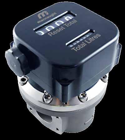
34 M-SERIES FLOW METERS MECHANICAL FLOW METERS The Mechanical Flow Meters range is the original meter range from Macnaught. They are available with reliable mechanical displays offer a measurement option for unpowered or remote sites. All Macnaught Flow Meters are supplied with an individual Test Report. EXPLODED DIAGRAM Output Choose between standard mechanical or heavy duty mechanical register M-SERIES FLOW METERS Rotor type Select rotor type based on the viscosity of the fluid and fluid type Materials of construction Choose material based on pressure and fluid type Port connection Based on desired pipe connection Port size Choose meter port size based on flow rate desired 32 Macnaught Positive Displacement Flow Meters
35 PRODUCT IDENTIFICATION SYSTEM F012-1S3 F MATERIALS OF CONSTRUCTION CATEGORY (METER/ROTOR/SEAL) MODELS AL/PPS/FKM F F AL/AL/FKM F M SS/PPS/FEP M S AL/SS/FEP S025 AL/AL/FEP S PORT SIZE 012 1/ ½ PORT CONNECTION 1 G (Litres Display) 2 NPT (US Gallons Display) 3 NPT (Litres Display) MODELS All Models M-SERIES FLOW METERS 4 BSP Rc (Litres Display) S 3 ROTOR MODELS S Standard Rotors Category F and M T* High Temperature Category M and S025 V OUTPUT High Viscosity *T type rotors are offered in Aluminium for category S040 to S100 PPS material for F012-F050 AL material for F075-F100, S040-S100 SS material for M025-M050 MODELS 3 Standard Mechanical Heavy Duty Mechanical All Models macnaught.com 33


36 M-SERIES FLOW METERS PULSE FLOW METERS (STANDARD) The Macnaught Pulse Flow Meter range are the original meter range from Macnaught. They offer a compact and robust metal body, manufactured from high quality grades of cast aluminium and stainless steel. For highly corrosive chemical applications, BR42B grade PPS material is used to deliver superior stability*. EXPLODED DIAGRAM M-SERIES FLOW METERS Output Choose between Hall Effect or Reed Switch Rotor type Select rotor type based on the viscosity of the fluid and fluid type Materials of construction Choose material based on pressure and fluid type Port connection Based on desired pipe connection Port size Choose meter port size based on flow rate desired 34 Macnaught Positive Displacement Flow Meters
37 PRODUCT IDENTIFICATION SYSTEM F006-1SA F MATERIALS OF CONSTRUCTION CATEGORY (BODY/ROTOR/SEAL) MODELS F AL/SS/FKM All Models M SS/SS/FFKM M006/M009 S AL/SS/FFKM S006/S009 CR PPS/PPS/FFKM PPS/PPS/FEP CR006 and CR009 CR PORT SIZE MODELS 006 1/4 All models 009 1/4 All models Category CR only PORT CONNECTION MODELS 1 G Category F, M and S only 2 NPT All models 4 Rc All models M-SERIES FLOW METERS S ROTOR TYPE MODELS S Standard F and CR category only T High Temp. Pulse M and S category only V High Viscosity 009 only; Not available for CR A OUTPUT TYPE 1 Reed/Hall MODELS Flying lead for 006/009 User connection for CR025 2 Reed/Reed 006/009 Single reed ONLY A B Reed/Hall DIN connection Reed/Reed DIN connection Not Available for CR025 macnaught.com 35


38 M-SERIES FLOW METERS PULSE FLOW METERS (HIGH PRESSURE) Macnaught High Pressure Flow Meters are manufactured from robust stainless steel body utilizing high quality billet suitable for use in the harshest environments. Designed to withstand pressures from 3000psi to 8000psi, the Macnaught High Pressure Flow Meters fit virtually any high pressure liquid measurement requirements. All Macnaught Flow Meters are supplied with an individual Test Report. EXPLODED DIAGRAM Output Choose between Hall Effect or Reed Switch M-SERIES FLOW METERS Rotor type Select rotor type based on the viscosity of the fluid and fluid type Port connection Based on desired pipe connection Port size Choose meter port size based on flow rate desired Materials of construction Choose material based on pressure and fluid type 36 Macnaught Positive Displacement Flow Meters
39 PRODUCT IDENTIFICATION SYSTEM MH009-1T1 MH MH MATERIALS OF CONSTRUCTION CATEGORY (METER/ROTOR/SEAL) SS/SS/FFKM SS/SS/FEP SS/PPS/FEP MODELS MH MH PORT SIZE 006 1/ / /2 PORT CONNECTION 1 G 2 NPT MODELS All Models MODELS All Models M-SERIES FLOW METERS T ROTOR TYPE MODELS T High Temp. Pulseerature All Models V High Viscosity MH009 and MH012 1 OUTPUT SWITCH TYPE 1 Pulse Output Single Hall for MH006/009. Reed/Hall for MH012 2 Pulse Output Single Reed for MH006/009. Dual Reed for MH012 macnaught.com 37
40 M1 ¼ PULSE FLOW METERS SUITABLE FOR FLOW RANGE GPH F006-1S1 Aluminium body with flying lead CR006-1SA PPS body with DIN variation M-SERIES FLOW METERS Macnaught ¼ Pulse Flow Meters are a small capacity meter in the M-SERIES range. Differentiated by its flow rate capabilities. Suitable for flows between GPH. The ¼ Pulse Flow Meters have an accuracy of +/- 0.5% and provides exceptional levels of reliability and durability. SPECIFICATIONS Materials of Construction Meter Body Rotor Seals Design Specifications Process Connections Technical Specifications Flow rate Aluminium Stainless Steel Fluorocarbon (FKM) ¼ G ¼ NPT 2-100L/hr USG/hr F006 S006 M006 CR L/hr USG/hr Aluminium Stainless Steel Perfluoroelastomer (FFKM) ¼ G ¼ NPT 2-100L/hr USG/hr L/hr USG/hr Stainless Steel Stainless Steel Perfluoroelastomer (FFKM) ¼ G ¼ NPT 2-100L/hr USG/hr L/hr USG/hr PPS PPS Perfluoroelastomer (FFKM) ¼ BSP (Rc) ¼ NPT 2-100L/hr USG/hr L/hr USG/hr Non-lubricating fluids 6-100L/hr USG/hr 6-100L/hr USG/hr 6-100L/hr USG/hr 6-100L/hr USG/hr Operating Temperature Range* ºC ºF ºC ºF ºC ºF ºC ºF Max. Operating Pressure 800 psi 55 bar 800 psi 55 bar 800 psi 55 bar 75 psi 5 bar Accuracy +/- 0.5% +/- 0.5% +/- 0.5% +/- 0.5% Repeatability Nominal K-Factor 3, Pulses/Gallon 3, Pulses/Gallon 3, Pulses/Gallon 3, Pulses/Gallon *Temperature based on standard pulse output - subject to change dependant on rotor and output type, contact Macnaught technical support for further investigations CR's are an M-SERIES meter. They are not modular in design and do not feature digital direct mount options. Across the M-series, differentiation is expressed through the material compatibility table etc as the key variable is wetted components. The CR is not it's own category rather a combination that suits particular conditions as is all the meters in the M-SERIES category it is classified with. This was the logic for the entire range. 38 Macnaught Positive Displacement Flow Meters
41 OUTPUT TYPES PREFIX OUTPUT SWITCH TYPE F006 S006 M006 CR006 1 Pulse output Reed/Hall Flying Lead 2 Pulse output Reed Flying Lead A Pulse output Reed/Hall DIN Connection B Pulse output Reed/Reed DIN Connection Available Not Available DIMENSIONS M006/F006/S006 DIN variation 51mm 13mm 17mm 64mm 59mm 42mm 17mm 50mm 59mm 42mm M006/F006/S006 Flying Lead CR006 DIN variation 51mm 51mm 13mm 51mm 1m 17mm 64mm 59mm 45mm 50mm 1m 59mm 17mm 45mm M-SERIES FLOW METERS CR006 Flying Lead macnaught.com 39
42 M1 ¼ HIGH PRESSURE FLOW METERS SUITABLE FOR FLOW RANGE GPH Also available as optional accessories: DR LCD Display (12mm) DRA LCD Display (12mm) with outputs MH006-1T1 Stainless steel body with pulser cap M-SERIES FLOW METERS Macnaught ¼ High Pressure Flow Meters are a small capacity meter in the M-SERIES range. Suitable for flows between GPH. The ¼ High Pressure Flow Meters are manufactured from high quality billet for enhanced material reliability with pressure ratings of up to 8000psi and have an accuracy of +/- 0.5% to provide exceptional levels of reliability and durability. SPECIFICATIONS Materials of Construction Meter Body Rotor Seals Design Specifications Process Connections Technical Specifications Flow rate Non-lubricating fluids Operating Temperature Range* Pressure Accuracy Repeatability Nominal K-Factor Stainless Steel Stainless Steel Perfluoroelastomer (FFKM) ¼ G ¼ NPT 2-100L/hr USG/hr 6-100L/hr USG/hr ºC ºF 8000 psi 557 bar +/- 0.5% 3, Pulses/Gallon MH L/hr USG/hr Pulse Output Options Pulser Pulser Local Display Options Type DR Type DRA Single Hall Effect Single Reed Switch LCD display (12mm) LCD display (12mm) No Outputs Outputs: Scaled Pulse, 4-20mA and Hi/Lo Flow Alarm *Temperature based on standard pulse output - subject to change dependant on rotor and output type, contact Macnaught technical support for further investigations 40 Macnaught Positive Displacement Flow Meters
43 DIMENSIONS MH ISOMETRIC VIEW MH006 with DR Display M-SERIES FLOW METERS ISOMETRIC VIEW macnaught.com 41


44 M2 ¼ PULSE FLOW METERS SUITABLE FOR FLOW RANGE GPH F009-1S1 Aluminium body with flying lead CR009-1SA PPS body with DIN variation M-SERIES FLOW METERS Macnaught ¼ Pulse Flow Meters are a small capacity meter in the M-SERIES range. Differentiated by its flow rate capabilities. Suitable for flows between GPH. The ¼ Pulse Flow Meters have an accuracy of +/- 0.5% and provides exceptional levels of reliability and durability. SPECIFICATIONS Materials of Construction Meter Body Rotor Seals Design Specifications Process Connections Technical Specifications Flow rate Operating Temperature Range* Max. Operating Pressure Accuracy Repeatability Nominal K-Factor Aluminium Stainless Steel Fluorocarbon (FKM) ¼ G ¼ NPT L/hr USG/hr ºC ºF 800 psi 55 bar +/- 0.5% 1, Pulses/Gallon F009 S009 M009 CR L/hr 4-132USG/hr Aluminium Stainless Steel Perfluoroelastomer (FFKM) ¼ G ¼ NPT L/hr USG/hr ºC ºF 800 psi 55 bar +/- 0.5% 1, Pulses/Gallon L/hr 4-132USG/hr Stainless Steel Stainless Steel Perfluoroelastomer (FFKM) ¼ G ¼ NPT L/hr USG/hr ºC ºF 800 psi 55 bar +/- 0.5% 1, Pulses/Gallon L/hr 4-132USG/hr PPS PPS Perfluoroelastomer (FFKM) ¼ BSP (Rc) ¼ NPT L/hr USG/hr ºC ºF 75 psi 5 bar +/- 1.0% 1, Pulses/Gallon L/hr 4-132USG/hr *Temperature based on standard pulse output - subject to change dependant on rotor and output type, contact Macnaught technical support for further investigations CR's are an M-SERIES meter. They are not modular in design and do not feature digital direct mount options. Across the M-series, differentiation is expressed through the material compatibility table etc as the key variable is wetted components. The CR is not it's own category rather a combination that suits particular conditions as is all the meters in the M-SERIES category it is classified with. This was the logic for the entire range. 42 Macnaught Positive Displacement Flow Meters
45 OUTPUT TYPES PREFIX OUTPUT SWITCH TYPE F009 S009 M009 CR009 1 Pulse output Reed/Hall Flying Lead 2 Pulse output Reed Flying Lead A Pulse output Reed/Hall DIN Connection B Pulse output Reed/Reed DIN Connection Available Not Available DIMENSIONS M009/F009/S009 DIN variation 51mm 13mm 17mm 64mm 59mm 42mm 17mm 50mm 59mm 42mm M009/F009/S009 Flying Lead CR009 DIN variation 51mm 51mm 13mm 51mm 1m 17mm 64mm 59mm 45mm 50mm 1m 59mm 17mm 45mm M-SERIES FLOW METERS CR009 Flying Lead macnaught.com 43

46 M2 ¼ HIGH PRESSURE FLOW METERS SUITABLE FOR FLOW RANGE GPH Also available as optional accessories: DR LCD Display (12mm) DRA LCD Display (12mm) with outputs MH009-1T1 Stainless steel body with pulser cap M-SERIES FLOW METERS Macnaught ¼ High Pressure Flow Meters are a small capacity meter in the M-SERIES range. Suitable for flows between GPH. The ¼ High Pressure Flow Meters are manufactured from high quality billet for enhanced material reliability with pressure ratings of up to 8000psi and have an accuracy of +/- 0.5% to provide exceptional levels of reliability and durability. SPECIFICATIONS Materials of Construction Meter Body Rotor Seals Design Specifications Process Connections Technical Specifications Flow rate Operating Temperature Range* Max. Operating Pressure Accuracy Repeatability Nominal K-Factor Stainless Steel Stainless Steel Perfluoroelastomer (FFKM) Threaded ¼ G ¼ NPT L/hr USG/hr ºC ºF 8000 psi 557 bar +/- 0.5% 1, Pulses/Gallon MH L/hr 4-132USG/hr Pulse Output Options Pulser Pulser Local Display Options Type DR Type DRA Single Hall Effect Single Reed Switch LCD display (12mm) LCD display (12mm) No Outputs Outputs: Scaled Pulse, 4-20mA and Hi/Lo Flow Alarm *Temperature based on standard pulse output - subject to change dependant on rotor and output type, contact Macnaught technical support for further investigations 44 Macnaught Positive Displacement Flow Meters
47 DIMENSIONS MH ISOMETRIC VIEW MH009 with DR Display M-SERIES FLOW METERS ISOMETRIC VIEW macnaught.com 45
 DRA LCD Display (12mm) with outputs MH012-1T1 Stainless steel body with pulser cap M-SERIES FLOW METERS Macnaught ½ High Pressure")

48 M4 ½ HIGH PRESSURE FLOW METERS SUITABLE FOR FLOW RANGE 0.5-8GPM Also available as optional accessories: DR LCD Display (12mm) DRA LCD Display (12mm) with outputs MH012-1T1 Stainless steel body with pulser cap M-SERIES FLOW METERS Macnaught ½ High Pressure Flow Meters are suitable for low to medium flow range of 0.5-8GPM. The ½ High Pressure Flow Meters are manufactured from high quality billet for enhanced material reliability with pressure ratings of up to 3000psi and have an accuracy of +/- 0.5% to provide exceptional levels of reliability and durability. SPECIFICATIONS Materials of Construction Meter Body Rotor Seals Design Specifications Process Connections Technical Specifications Flow rate Operating Temperature Range* Pressure Accuracy Repeatability Nominal K-Factor Stainless Steel Stainless Steel PPS option PTFE encapsulated (FEP) Threaded ½ G ½ NPT 3-25L/min USG/min ºC ºF 3000psi 207 Bar +/- 1.0% +/ Pulses/Gallon MH L/min 0.5-8USG/min Pulse Output Options Pulser Pulser Local Display Options Type DR Type DRA Dual Reed/Hall Dual Reed Switch LCD display (12mm) LCD display (12mm) No Outputs Outputs: Scaled Pulse, 4-20mA and Hi/Lo Flow Alarm *Temperature based on standard pulse output - subject to change dependant on rotor and output type, contact Macnaught technical support for further investigations 46 Macnaught Positive Displacement Flow Meters
49 DIMENSIONS MH ISOMETRIC VIEW MH012 with DR Display 95 M-SERIES FLOW METERS 100 ISOMETRIC VIEW macnaught.com 47

50 M4 ½ MECHANICAL METERS SUITABLE FOR FLOW RANGE 0.5-8GPM Output variations: Type 3 Standard Mechanical Display Type 4 Heavy Duty Mechanical Display F012-1S3 Aluminium body with standard mechanical display M-SERIES FLOW METERS Designed and built to suit a broad range of industrial applications, the Macnaught ½ Mechanical Meters are suitable for flows between 0.5-8GPM. The ½ Mechanical Meters have an accuracy of +/- 1.0% and provides exceptional levels of reliability and durability. These meters are an ideal solution for remote sites or where ease of installation, accuracy and reliability are the priority. SPECIFICATIONS Materials of Construction Meter Body Rotor Seals Design Specifications Process Connections Technical Specifications Flow rate Max. Operating Temperature Max. Operating Pressure Accuracy Repeatability Mechanical Display Type 3 - Standard Type 4 - Heavy Duty Cast Aluminium PPS Fluorocarbon (FKM) Threaded ½ G ½ NPT 3-25L/min USG/min ºC ºF 500 psi 35 bar +/- 1.0% Polypropylene (IP56) Aluminium (IP67) F L/min 0.5-8USG/min Cast Stainless Steel PPS Stainless Steel PTFE encapsulated (FEP) Threaded ½ G ½ NPT 3-25L/min USG/min ºC ºF 500psi 35 bar +/- 1.0% +/-0.03% Polypropylene (IP56) Aluminium (IP67) M L/min 0.5-8USG/min 48 Macnaught Positive Displacement Flow Meters
51 DIMENSIONS F012 M012 DISPLAY HEIGHT - A TYPE 3 MECHANICAL REGISTER - STANDARD TYPE 4 MECHANICAL REGISTER - HEAVY DUTY 122mm 115mm 24mm 64mm A 100mm 106mm 48mm 148mm 154mm 173mm TYPE 4 M-SERIES FLOW METERS macnaught.com 49
 DRA LCD Display (12mm) with outputs ER LCD Display (17mm) ERA LCD Display (17mm) with outputs ERB LCD Display (17mm) with batch")

52 M7 1 PULSE FLOW METERS SUITABLE FOR FLOW RANGE GPM Also available as optional accessories: DR LCD Display (12mm) DRA LCD Display (12mm) with outputs ER LCD Display (17mm) ERA LCD Display (17mm) with outputs ERB LCD Display (17mm) with batch control output CR025-2S1 PPS body with pulser cap M-SERIES FLOW METERS The Macnaught 1 Pulse Flow Meters are specialised meters suitable for aggressive chemicals and water based products. Suitable for flows between GPM. The 1 Pulse Flow Meters have an accuracy of +/- 0.5% and provides exceptional levels of reliability and durability. SPECIFICATIONS Materials of Construction Meter Body Rotor Seals Design Specifications Process Connections Technical Specifications Flow rate Operating Temperature Range Max. Operating Pressure Accuracy Repeatability Nominal K-Factor PPS PPS PTFE encapsulated (FEP) Threaded 1 BSP (Rc) 1 NPT 8-70L/min USG/min ºC ºF 150 psi 10 Bar +/- 0.5% Pulses/Gallon CR L/min USG/min Pulse Output Options Pulser Pulser Local Display Options Type DR Type DRA Reed/Hall Effect Reed/Reed Switch Dual Hall LCD display (12mm) LCD display (12mm) No Outputs Outputs: Scaled Pulse, 4-20mA and Hi/Lo Flow Alarm 50 Macnaught Positive Displacement Flow Meters
53 DIMENSIONS CR025 82mm 35mm 100mm ISOMETRIC VIEW 27mm 100mm 109mm CR025 with ER Display 161mm 85mm 82mm ISOMETRIC VIEW M-SERIES FLOW METERS 27mm 109mm CR025 with DR Display 109mm 27mm 82mm 80mm 102mm macnaught.com 51
54 M10 1 MECHANICAL METERS SUITABLE FOR FLOW RANGE GPM Output variations: Type 3 Standard Mechanical Display Type 4 Heavy Duty Mechanical Display F025-1S3 Aluminium body with standard mechanical display M-SERIES FLOW METERS Designed and built to suit a broad range of industrial applications, the Macnaught 1 Mechanical Meters are suitable for flows between GPM. The 1 mechanical meters have an accuracy of +/- 1.0% and provides exceptional levels of reliability and durability. These meters are an ideal solution for remote sites or where ease of installation, accuracy and reliability are the priority. SPECIFICATIONS Materials of Construction Meter Body Rotor Seals Design Specifications Process Connections Technical Specifications Flow rate Operating Temperature Range* Max. Operating Pressure** Accuracy Repeatability Mechanical Display Type 3 - Standard Type 4 - Heavy Duty Cast Aluminium PPS Fluorocarbon (FKM) Threaded 1 G 1 NPT L/min USG/min ºC ºF 500 psi 35 Bar +/- 1.0% Polypropylene (IP56) Aluminium (IP67) F025 M025 S025 Flange ANSI CLASS 150 DIN PN16 JIS 10k 6-120L/min USG/min Cast Stainless Steel PPS Stainless Steel PTFE encapsulated (FEP) Threaded 1 G 1 NPT L/min USG/min ºC ºF 500 psi 35 Bar +/- 1.0% Polypropylene (IP56) Aluminium (IP67) Flange ANSI CLASS 150 DIN PN16 JIS 10k 6-120L/min USG/min Cast Aluminium Stainless Steel PTFE encapsulated (FEP) Threaded 1 G 1 NPT L/min USG/min ºC ºF 500 psi 35 Bar +/- 1.0% Polypropylene (IP56) Aluminium (IP67) Flange ANSI CLASS 150 DIN PN16 JIS 10k 6-120L/min USG/min *Temperature based on standard rotors - subject to change in M025 when changing rotor material, contact Macnaught technical for further investigations **Pressure subject to change as per flange rating 52 Macnaught Positive Displacement Flow Meters
55 DIMENSIONS 284mm F025 S mm A 100mm A F025-1S3 133mm 28mm 56mm 106mm ANSI M mm 143mm 28mm 133 DISPLAY HEIGHT - A TYPE 3 MECHANICAL REGISTER - STANDARD 28 ANSI TYPE 4 MECHANICAL REGISTER - HEAVY DUTY M-SERIES FLOW METERS 115mm 162mm 158mm 184mm 173mm macnaught.com 53

56 M40 1½ MECHANICAL METERS SUITABLE FOR FLOW RANGE GPM Output variations: Type 3 Standard Mechanical Display Type 4 Heavy Duty Mechanical Display F040-1S3 Aluminium body with standard mechanical display M-SERIES FLOW METERS Designed and built to suit a broad range of industrial applications, the Macnaught 1½ Mechanical Meters are suitable for flows between GPM. The 1½ Mechanical Meters have an accuracy of +/- 1.0% and provides exceptional levels of reliability and durability. These meters are an ideal solution for remote sites or where ease of installation, accuracy and reliability are the priority. SPECIFICATIONS Materials of Construction Meter Body Rotor Seals Design Specifications Process Connections Technical Specifications Flow rate Operating Temperature Range* Max. Operating Pressure** Accuracy Repeatability Mechanical Display Type 3 - Standard Type 4 - Heavy Duty Cast Aluminium PPS Fluorocarbon (FKM) Threaded 1½ G 1½ NPT L/min 4-62USG/min ºC ºF 500 psi 35 Bar +/- 1.0% Polypropylene (IP56) Aluminium (IP67) F040 M040 S040 Flange ANSI CLASS 150 DIN PN16 JIS 10k L/min USG/min Cast Stainless Steel PPS Stainless Steel PTFE encapsulated (FEP) Threaded 1½ G 1½ NPT L/min 4-62USG/min ºC ºF 500 psi 35 Bar +/- 1.0% Polypropylene (IP56) Aluminium (IP67) Flange ANSI CLASS 150 DIN PN16 JIS 10k L/min USG/min Cast Aluminium Aluminium Stainless Steel PTFE encapsulated (FEP) Threaded 1½ G 1½ NPT L/min 4-62USG/min ºC ºF 500 psi 35 Bar +/- 1.0% Polypropylene (IP56) Aluminium (IP67) Flange ANSI CLASS 150 DIN PN16 JIS 10k L/min USG/min *Temperature based on standard rotors - subject to change in M040 when changing rotor material, contact Macnaught technical support for further investigations **Pressure subject to change as per flange rating 54 Macnaught Positive Displacement Flow Meters
57 DIMENSIONS F040 M040 S040 DISPLAY HEIGHT - A A 44mm 132mm 124mm 270mm* ANSI TYPE 3 MECHANICAL REGISTER - STANDARD TYPE 4 MECHANICAL REGISTER - HEAVY DUTY 190mm 144mm 216mm 178mm 173mm M-SERIES FLOW METERS *Length subject to change refer to appendix B (pg. 75) for full dimension variations macnaught.com 55

58 M50 2 MECHANICAL METERS SUITABLE FOR FLOW RANGE GPM Output variations: Type 3 Standard Mechanical Display Type 4 Heavy Duty Mechanical Display F050-1S3 Aluminium body with standard mechanical display and BSP thread adaptors M-SERIES FLOW METERS Designed and built to suit a broad range of industrial applications, the Macnaught 2 Mechanical Meters are suitable for flows between GPM. The 2 Mechanical Meters have an accuracy of +/- 1.0% and provides exceptional levels of reliability and durability. These meters are an ideal solution for remote sites or where ease of installation, accuracy and reliability are the priority. SPECIFICATIONS Materials of Construction Meter Body Rotor Seals Design Specifications Process Connections Technical Specifications Flow rate Cast Aluminium PPS Fluorocarbon (FKM) Threaded 2 G 2 NPT L/min 4-130USG/min F050 M050 S050 Flange ANSI CLASS 150 DIN PN16 JIS 10k L/min 4-130USG/min Cast Stainless Steel PPS Stainless Steel PTFE encapsulated (FEP) Threaded 2 G 2 NPT L/min 4-130USG/min Flange ANSI CLASS 150 DIN PN16 JIS 10k L/min 4-130USG/min Cast Aluminium Stainless Steel Aluminium PTFE encapsulated (FEP) Threaded 2 G 2 NPT L/min 4-130USG/min Flange ANSI CLASS 150 DIN PN16 JIS 10k L/min 4-130USG/min Operating Temperature Range* ºC ºF ºC ºF ºC ºF Max. Operating Pressure** 500psi 35 Bar 500psi 35 Bar 500psi 35 Bar Accuracy +/- 1.0% +/- 1.0% +/- 1.0% Repeatability Mechanical Display Type 3 - Standard Polypropylene (IP56) Polypropylene (IP56) Polypropylene (IP56) Type 4 - Heavy Duty Aluminium (IP67) Aluminium (IP67) Aluminium (IP67) *Temperature based on standard rotors - subject to change in M040 when changing rotor material, contact Macnaught technical support for further investigations **Pressure subject to change as per flange rating 56 Macnaught Positive Displacement Flow Meters
59 DIMENSIONS F050 M050 S050 DISPLAY HEIGHT - A TYPE 3 TYPE 4 MECHANICAL REGISTER - STANDARD MECHANICAL REGISTER - HEAVY DUTY 178mm 195mm 215mm 241mm 60mm 157mm A 120mm 89mm 106mm 264mm 210mm ANSI/DIN/JIS G/NPT M-SERIES FLOW METERS 186mm *Length subject to change refer to appendix B (pg. 75) for full dimension variations Refer to appendix B (pg. 76) for dimensions of air eliminators macnaught.com 57

60 M80 3 MECHANICAL METERS SUITABLE FOR FLOW RANGE GPM Output variations: Type 4 Heavy Duty Mechanical Display F075-1S4 Aluminium body with heavy duty mechanical display and ANSI flanges M-SERIES FLOW METERS Designed and built to suit a broad range of industrial applications, the Macnaught 3 Mechanical Meters are suitable for flows between GPM. The 3 Mechanical Meters have an accuracy of +/- 1.0% and provides exceptional levels of reliability and durability. These meters are an ideal solution for remote sites or where ease of installation, accuracy and reliability are the priority. SPECIFICATIONS Materials of Construction Meter Body Rotor Seals Design Specifications Process Connections Technical Specifications Flow rate Operating Temperature Range Max. Operating Pressure** Accuracy Repeatability Cast Aluminium Aluminium Fluorocarbon (FKM) Threaded 3 G 3 NPT L/min USG/min ºC ºF 175 psi 12 Bar +/- 1.0% F075 Flange ANSI CLASS 150 DIN PN16 JIS 10k L/min 5-194USG/min Cast Aluminium Aluminium PTFE encapsulated (FEP) Threaded 3 G 3 NPT L/min USG/min ºC ºF 175 psi 12 Bar +/- 1.0% S075 Flange ANSI CLASS 150 DIN PN16 JIS 10k L/min 5-194USG/min Pulse Output Options Type 4 - Heavy Duty Aluminium (IP67) Aluminium (IP67) **Pressure subject to change as per flange rating 58 Macnaught Positive Displacement Flow Meters
61 DIMENSIONS F075 S mm 141mm 254mm 226mm 85mm 200mm 78mm 436mm 302mm ANSI/DIN/JIS G/NPT M-SERIES FLOW METERS *Length subject to change refer to appendix B (pg. 75) for full dimension variations Refer to appendix B (pg. 76) for dimensions of air eliminators macnaught.com 59

62 M100 4 MECHANICAL METERS SUITABLE FOR FLOW RANGE GPM Output variations: Type 4 Heavy Duty Mechanical Display F100-1S4 Aluminium body with heavy duty mechanical display with ANSI flanges M-SERIES FLOW METERS Designed and built to suit a broad range of industrial applications, the Macnaught 4 Mechanical Meters are suitable for flows between GPM. Suitable for fuels, lubricants and non-corrosive fluids of up to a viscosity of 1000cP. The 4 Mechanical Meters have an accuracy of +/- 1.0% and provides exceptional levels of reliability and durability. These meters are an ideal solution for remote sites or where ease of installation, accuracy and reliability are the priority. SPECIFICATIONS Materials of Construction Meter Body Rotor Seals Design Specifications Process Connections Technical Specifications Flow rate Operating Temperature Range Max. Operating Pressure*** Accuracy Repeatability Cast Aluminium Aluminium Fluorocarbon (FKM) Threaded 3 G 3 NPT L/min USG/min ºC ºF 175 psi 12 Bar +/- 1.0% F100 Flange 4 ANSI CLASS DIN PN16 4 JIS 10k L/min USG/min Cast Aluminium Aluminium PTFE encapsulated (FEP) Threaded 3 G 3 NPT L/min USG/min ºC ºF 175 psi 12 Bar +/- 1.0% S100 Flange 4 ANSI CLASS DIN PN16 4 JIS 10k L/min USG/min Pulse Output Options Type 4 - Heavy Duty Aluminium (IP67) Aluminium (IP67) **Pressure subject to change as per flange rating 60 Macnaught Positive Displacement Flow Meters
63 DIMENSIONS F100-1S4 S100-1S4 212mm 191mm 339mm 220mm 85mm 246mm 108mm 583mm* 302mm* ANSI/DIN/JIS G/NPT M-SERIES FLOW METERS *Length subject to change refer to appendix B (pg. 75) for full dimension variations Refer to appendix B (pg. 76) for dimensions of air eliminators macnaught.com 61
64


65 ACCESSORIES
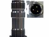
66 ACCESSORIES PULSER MODULES The Pulser Output Options are designed to complement the MX Blind meters series. These options provide the flexibility to apply a style of housing that best satisfies the application requirements. TYPE A STANDARD PULSE* TYPE B INTRINSICALLY SAFE TYPE N INTRINSICALLY SAFE TYPE T HIGH TEMP. PULSEERATURE Switch Type Reed/Hall Effect NPN open collector NAMUR NPN open collector Construction PP (polypropylene) Stainless Steel Cuzn, Chrome plated Stainless Steel IP rating IP67 IP67 IP67 IP67 Max temp 120 C (248 F) 85 C (185 F) 85 C (185 F) 150 C (302 F) Intrinsically safe Approvals *Options of lengths: 1m, 5m and 10m PULSER MODULE OPTIONS ATEX, CSA, FM II I G Ex ia IIC T6 ATEX, IECEx II G Ex ia IIC T4..T6 Ga II 1 D Ex ia IIIC T115OC Da Macnaught offer a range of Pulser modules to suit a wide variety of industrial flow metering needs. Incorporating Reed and NPN Open Collector switching technology and locking mechanism to facilitate simple integration into any logging and control system. DIN COMPACT INDUSTRIAL PULSER CAP Output Pulser Pulser ACCESSORIES Cable connection (M12) DIN socket M20 or ½ NPT Switch Type Reed/Hall Effect Dual Reed Switch Dual Hall Effect Reed/Hall Effect Dual Reed Switch Construction PP (polypropylene) Aluminium or Stainless Steel IP rating IP67 IP67 Max temp 120ºC (248ºF) 120ºC (248ºF) Part number Hall/Hall Switch MXD-HH Reed/Reed Switch MXD-RR Reed/Hall Switch MXD-RH Aluminium MXD-ACM-1 (Reed/Hall) MXD-ACM-2 (Reed/Reed) MXD-ACN-1 (Reed/Hall) MXD-ACN-2 (Reed/Reed) Stainless Steel MXD-SCM-1 (Reed/Hall) 64 Macnaught Positive Displacement Flow Meters
67 PR DIGITAL DISPLAY SERIES (12MM DIGIT) The PR Series is a fully programmable 12mm LCD Digital Register displaying Flow Rate, Accumulated (Nonresettable) and Batch (Resettable) Totals. The output options available include 4-20mA output, scaled pulse output and a Hi/Lo Flow Alarm. Rated at IP67, the UV resistant glass reinforced polypropylene housing makes the PR Series suitable for both indoor and outdoor use in light-medium duty industrial applications. The PR display is also available in both Meter Mount and Remote Mount version METER MOUNT TYPE D PR DISPLAY TYPE E PRA DISPLAY Description Liquid Crystal Display Liquid Crystal Display with outputs Construction PP (polypropylene) PP (polypropylene) Wall mount option PR-WM PRA-WM IP rating IP67 IP67 Max temp 60ºC (140ºF) 60ºC (140ºF) Display Digit size (upper/lower) Accumulated total Resettable total Preset total Flow rate Outputs 4-20 ma (passive) Pulse/Transistor Output Flow Alarm Batch Control output 12mm/8mm CHECK CHECK CHECK CHECK CHECK 12mm/8mm CHECK CHECK DR DIGITAL DISPLAY SERIES (12MM DIGIT) METER MOUNT DR DRA Description Reflective, UV resistant numeric and alphanumeric LCD Reflective, UV resistant numeric and alphanumeric LCD Construction Aluminium exterior with polycarbonate windows Aluminium exterior with polycarbonate windows ACCESSORIES Wall mount option DR-WM DRA-WM IP rating IP67 IP67 Max temp 60ºC (140ºF) 60ºC (140ºF) Display Digit size (upper/lower) Accumulated total Resettable total Preset total Flow rate Outputs 4-20 ma (passive) Pulse/Transistor Output Flow Alarm Batch Control output 12mm/8mm CHECK CHECK CHECK CHECK CHECK 12mm/8mm CHECK CHECK macnaught.com 65
68 ACCESSORIES ER DIGITAL DISPLAY SERIES (17MM DIGIT) The ER Series is a fully programmable 17mm LCD Digital Register displaying Flow Rate, Accumulated (Nonresettable) and Batch (Resettable) Totals. The output options available include 4-20mA and scaled pulse output. Rated at IP67, the robust Aluminium housing makes the ER Series suitable for both indoor and outdoor use in heavy duty industrial applications. The ER display is also available in both Meter Mount (Aluminium) and Remote Mount (Aluminium or plastic) versions. METER MOUNT TYPE F ER DISPLAY TYPE G ERA DISPLAY TYPE H ERB DISPLAY Description Liquid Crystal Display Liquid Crystal Display with outputs Single stage Batch Controller Construction Aluminium Aluminium Aluminium IP rating IP67 IP67 IP67 Max temp 120 C (248 F) 80 C (176 F) 80 C (176 F) Display Digit size (upper/lower) Accumulated total Resettable total Preset total Flow rate 17mm/8mm CHECK 17mm/8mm CHECK 17mm/8mm CHECK Outputs 4-20 ma (passive) Pulse/Transistor Output Flow Alarm Batch Control output CHECK CHECK CHECK CHECK CHECK CHECK CHECK CHECK CHECK ACCESSORIES REMOTE MOUNT ER-RMP ER-RMA ERA-RMP ERA-RMA ERB-RMP ERB-RMA Description Liquid Crystal Display Liquid Crystal Display with outputs Single stage Batch Controller Construction Aluminium or GRP (plastic) Aluminium or GRP (plastic) Aluminium or GRP (plastic) IP rating IP67 IP67 IP67 Mounting Wall mount Wall mount Wall mount Display Digit size (upper/lower) Accumulated total Resettable total Preset total Flow rate 117mm/8mm CHECK 117mm/8mm CHECK 17mm/8mm CHECK Outputs 4-20 ma (passive) Pulse/Transistor Output Mechanical relay output Flow Alarm Batch Control output CHECK CHECK CHECK CHECK CHECK CHECK CHECK CHECK CHECK CHECK CHECK CHECK Ex approved part numbers ERX-RMA (Aluminium) ERX-RMP (Plastic) ERAX-RMA (Aluminium) ERAX-RMP (Plastic) ERBX-RMA (Aluminium) ERBX-RMP (Plastic) 66 Macnaught Positive Displacement Flow Meters
69 ER DIGITAL DISPLAY SERIES (17MM DIGIT) REMOTE MOUNT ERB-PM ERS-RMP ERS-RMA Description Two stage Batch Controller Differential Flow Computer Construction Aluminium front panel Aluminium or GRP (plastic) IP rating IP67 (NEMA 4X) IP67 (NEMA 4X) Mounting DIN panel mount Wall mount Display Digit size (upper/lower) Accumulated total Resettable total Preset total Flow rate Outputs 4-20 ma (passive) Pulse/Transistor Output Mechanical relay output Flow Alarm Batch Control output 17mm/8mm CHECK 17mm/8mm CHECK CHECK CHECK CHECK ACCESSORIES macnaught.com 67
: Part Number")
YS040-01 (NPT) WALL MOUNT BRACKET ACCESSORIES DESCRIPTION Aluminium wall mount bracket to suit models MX06-25»» Suitable for MX06: Part Number MXA-06-WM»» Suitable for MX09: Part Number")
70 ACCESSORIES AIR ELIMINATOR & STRAINER DESCRIPTION Aluminium body SS 316 basket Viton Seals Mesh size: 100 Mesh (150µ) Air eliminators are available in 3 sizes: - 2": Part Number BSA050-3": Part Number BSA075-4": Part Number BSA100 Y TYPE STRAINER DESCRIPTION Body: CF8M Screen: SS316 Working press: 800 psi/pn40 Y-type strainers are available in 4 sizes:»» ¼ 200 mesh (74µ): Part Number YS (BSP) YS (NPT)»» ½ 60 mesh (250µ): Part Number YS (BSP)YS (NPT)»» 1 60 mesh (250µ): Part Number YS (BSP)YS (NPT)»» 1½ 60 mesh (250µ): Part Number YS (BSP)YS (NPT) WALL MOUNT BRACKET ACCESSORIES DESCRIPTION Aluminium wall mount bracket to suit models MX06-25»» Suitable for MX06: Part Number MXA-06-WM»» Suitable for MX09: Part Number MXA-09-WM»» Suitable for MX12: Part Number MXA-12-WM»» Suitable for MX19-25: Part Number MXA-25-WM 68 Macnaught Positive Displacement Flow Meters
: Part Number MXD-C1.")
: Part Number MXD-C1-5S Please note: The Sensor cable should be ordered separate to the DIN Pulser Module.")
71 SIGNAL CABLE DESCRIPTION The Sensor Cable is a M12 5 position female connector cable, to supplement the DIN Pulser Module Manufactured form polyurethane, the sensor cable is highly resistant to acids, alkaline solutions, solvents and salt water The Sensor cable is available in 4 options:»» 1.5 meters (right angle): Part Number MXD-C1.5»» 5 meters (right angle): Part Number MXD-C5»» 10 meters (right angle): Part Number MXD-C10»» 1.5 meters (straight): Part Number MXD-C1-5S Please note: The Sensor cable should be ordered separate to the DIN Pulser Module. FIELD ATTACHABLE CONNECTOR DESCRIPTION The Field Attachable Connector is a M12, right angled female connector, to complement the DIN Pulser Module. The connector offers flexible on-site assembly via its 5 position, screw connection facility Part Number MXD-CF ACCESSORIES macnaught.com 69
 to MX SERIES Flow Meters.")

72 ACCESSORIES DIGITAL FLOW METER EXTENSION ADAPTORS Macnaught Digital Flow Meter Extensions Adaptors are manufactured from Stainless Steel 316 are suitable for upgrading M-SERIES Flow Meters* (early models) to MX SERIES Flow Meters. Since end-to-end length of MX Series flow meters are smaller than M-Series flow meters, these extension adaptors allow for users to compensate the extra length and will adjust perfectly in existing pipework. Macnaught offers these extension adaptors free of charge on request with every purchase of a MX meter. SPECIFICATIONS MX12 MX19 MX25 MX40 MX50 Part Number Telfon Seals Viton Seals MX12A-TE MX12A-V MX19A-TE MX19A-V MX25AA-TE MX25AS-TE MX25AA-V MX40A-TE MX40A-V MX50A-TE MX50A-V Size ½ ¾ 1 1½ 2 Suits models MX12 MX19 MX25 MX40 MX50 DIMENSIONS MX25P (SS) P/N: MX25A-V suitable for MX25F MX25A-TE suitable for MX25P or S ACCESSORIES MX06F (AL) MX06S (AL) MX06P (SS) MX09F (AL) MX09S (AL) MX09P (SS) F006 (AL) F009 (AL) S006 (AL) S009 (AL) M1 (AL) M2 (AL) MX12P (SS) MX12F (AL) MX12S (AL) F012 (AL) S012 (AL) M4 (AL) MX19P (SS) MX19F (AL) MX19S (AL) M025 (SS) M10 (SS) MX25F (AL) MX25S (AL) P/N: MX25A-V suitable for MX25F MX25A-TE suitable for MX25P or S M006 (SS) M009 (SS) M1 (SS) M2 (SS) F019 (AL) S019 (AL) M6 (AL) 50mm M012 (SS) M4 (SS) F025 S025 (AL) (AL) 60mm 71mm 100mm 102mm 133mm P/N: MX12A-V suitable for MX12F MX12A-TE suitable for MX12P or S P/N: MX19A-V suitable for MX19F MX19A-TE suitable for MX19P or S M10 (AL) 133mm 143mm *Applicable only for flow meters from 1/2 to 2 with BSP threaded connections. 70 Macnaught Positive Displacement Flow Meters
POSITIVE DISPLACEMENT FLOW METERS
 POSITIVE DISPLACEMENT FLOW METERS ABOUT MACNAUGHT Macnaught Pty Ltd is a privately owned manufacturing company based in Australia, established in 1948. Macnaught s experience in Positive Displacement Flow
MX-SERIES OVAL GEAR FLOW METERS
 Data Sheet MX-SERIES OVAL GEAR FLOW METERS Supplied by.com Call us on +44 (0)118 916 9420 Email info@247able.com MX-Series Oval Gear Flow Meters Features and Advantages P From ¼ DN8 at 0.5LPH to 4 DN100
OVAL GEAR FLOWMETER ELECTRONIC MODEL 006/009 (¼ )
") INST-006/009P_R9 06/2015 OVAL GEAR FLOWMETER ELECTRONIC MODEL 006/009 (¼ ) INSTRUCTION MANUAL F Serial Meters To the Owner PLEASE READ THIS SAFTEY INFORMATION CAREFULLY BEFORE USE. Read and retain this
INST-006/009P_R9 06/2015 OVAL GEAR FLOWMETER ELECTRONIC MODEL 006/009 (¼ ) INSTRUCTION MANUAL F Serial Meters To the Owner PLEASE READ THIS SAFTEY INFORMATION CAREFULLY BEFORE USE. Read and retain this
macnaught flow measurement
 macnaught flow measurement industrial flow meters macnaught.com.au flow meters m-series industrial macnaught flow measurement The M & MH range from Macnaught are positive displacement oval gear flowmeters
macnaught flow measurement
 macnaught flow measurement solvent flow meters macnaught.com.au flow meters solvent macnaught flow measurement The "S" range of oval gear fuel and oil meters from Macnaught are positive displacement oval
OVAL GEAR FLOWMETER ELECTRONIC MODEL 019 / ¾
 INST-019P_R4 11/2012 OVAL GEAR FLOWMETER ELECTRONIC MODEL 019 / ¾ INSTRUCTION MANUAL To the Owner PLEASE READ THIS SAFTEY INFORMATION CAREFULLY BEFORE USE. Read and retain this instruction manual to assist
macnaught flow measurement
 macnaught flow measurement fuel and oil meters macnaught.com.au flow meters fuel and oil macnaught flow measurement The F range of oval gear fuel and oil meters from Macnaught are positive displacement
MX06 - MX100 OVAL GEAR FLOWMETER SERIES
 MXL-INST Rev 7 04/2016 MX06 - MX100 OVAL GEAR FLOWMETER SERIES INSTRUCTION MANUAL To the Owner Please read and retain this instruction manual to assist you in the operation and maintenance of this product.
MX06 - MX100 OVAL GEAR FLOWMETER SERIES APPROVED FOR USE IN HAZARDOUS AREAS
 MXEX-INST Rev 9.0 04/2016 MX06 - MX100 OVAL GEAR FLOWMETER SERIES APPROVED FOR USE IN HAZARDOUS AREAS INSTRUCTION MANUAL To the Owner Page 1 of 33 index Installation Pre-installation checks. Page 3 Operating
OVAL GEAR FLOWMETER MECHANICAL MODEL 075 (3 )
") INST-075M_R4 11/2012 OVAL GEAR FLOWMETER MECHANICAL MODEL 075 (3 ) INSTRUCTION MANUAL To the Owner PLEASE READ THIS SAFTEY INFORMATION CAREFULLY BEFORE USE. Read and retain this instruction manual to assist
INST-075M_R4 11/2012 OVAL GEAR FLOWMETER MECHANICAL MODEL 075 (3 ) INSTRUCTION MANUAL To the Owner PLEASE READ THIS SAFTEY INFORMATION CAREFULLY BEFORE USE. Read and retain this instruction manual to assist
OVAL GEAR FLOWMETER MECHANICAL MODEL 012 (½ )
") INST-012M_R4 11/2012 OVAL GEAR FLOWMETER MECHANICAL MODEL 012 (½ ) INSTRUCTION MANUAL To the Owner PLEASE READ THIS SAFTEY INFORMATION CAREFULLY BEFORE USE. Read and retain this instruction manual to assist
INST-012M_R4 11/2012 OVAL GEAR FLOWMETER MECHANICAL MODEL 012 (½ ) INSTRUCTION MANUAL To the Owner PLEASE READ THIS SAFTEY INFORMATION CAREFULLY BEFORE USE. Read and retain this instruction manual to assist
Positive displacement flowmeter for continuous flow measurement
 8070 Positive displacement flowmeter for continuous flow measurement High accuracy Medium with high viscosity Mounting and dismounting of the electronics by a quarter-turn Connection to Bürkert devices
MODEL MX75 3 OVAL GEAR FLOWMETER
 Installation & Maintenance Instructions MODEL MX75 3 OVAL GEAR FLOWMETER Supplied by.com Call us on +44 (0)118 916 9420 Email info@247able.com MXL-INST75 Rev 1 06/2013 MODEL MX75 3 OVAL GEAR FLOWMETER
OVAL GEAR FLOWMETER ELECTRONIC MODEL 006/009 (¼ )
") 012 Puls 07.11 OVAL GEAR FLOWMETER ELECTRONIC MODEL 006/009 (¼ ) INSTRUCTION MANUAL To the Owner PLEASE READ THIS SAFTEY INFORMATION CAREFULLY BEFORE USE. Read and retain this instruction manual to assist
012 Puls 07.11 OVAL GEAR FLOWMETER ELECTRONIC MODEL 006/009 (¼ ) INSTRUCTION MANUAL To the Owner PLEASE READ THIS SAFTEY INFORMATION CAREFULLY BEFORE USE. Read and retain this instruction manual to assist
POSITIVE DISPLACEMENT FLOWMETERS
 MS589 0409 00 POSITIVE DISPLACEMENT FLOWMETERS M80 SERIES INSTRUCTION MANUAL M80 Pulse; Standard LCD; Deluxe LCD; From serial No.CXXXX TO THE OWNER Please take a few minutes to read through this manual
OVAL GEAR FLOWMETER MECHANICAL MODEL 012 (½ )
") 012 Mech 07.11 OVAL GEAR FLOWMETER MECHANICAL MODEL 012 (½ ) INSTRUCTION MANUAL To the Owner PLEASE READ THIS SAFTEY INFORMATION CAREFULLY BEFORE USE. Read and retain this instruction manual to assist
012 Mech 07.11 OVAL GEAR FLOWMETER MECHANICAL MODEL 012 (½ ) INSTRUCTION MANUAL To the Owner PLEASE READ THIS SAFTEY INFORMATION CAREFULLY BEFORE USE. Read and retain this instruction manual to assist
OVAL GEAR FLOWMETER ELECTRONIC MODEL 025 / 1
 025 Puls 07.11 OVAL GEAR FLOWMETER ELECTRONIC MODEL 025 / 1 INSTRUCTION MANUAL To the Owner PLEASE READ THIS SAFTEY INFORMATION CAREFULLY BEFORE USE. Read and retain this instruction manual to assist you
MODEL MX12 1/2 OVAL GEAR FLOWMETER
 MXL-INST12 Rev 4 12/2013 MODEL MX12 1/2 OVAL GEAR FLOWMETER INSTRUCTION MANUAL To the Owner Please read and retain this instruction manual to assist you in the operation and maintenance of this product.
OM SERIES OVAL GEAR METERS. OM SERIES Oval Gear Meters
 Oval Gear Meters OVAL GEAR METERS OM Series Oval Gear Meters are designed for low flow and high accuracy. OM Series Meters are great for viscous fluids. Units are available with from either a Reed Switch
Operating Instructions for Oval Wheel Flowmeter. Model: DOC
 Operating Instructions for Oval Wheel Flowmeter Model: DOC We don t accept warranty and liability claims neither upon this publication nor in case of improper treatment of the described products. The document
OMP Positive Displacement Flowmeters
 Flow Ranges From 0.53 to 26 GPH Through 4 to 132 GPH Handles Viscosities to 1,000,000 cps Handles Viscosities to 1,000,000 cps Low Head Loss Oval Gear Design OMP Series Medium & High Flow Meters OMP-1
Type 2712 (8630) Continuous TopControl System. General data Compatibility Materials of wetted parts Body Rotor Shaft Seal
 Continuous TopControl System. General data Compatibility Materials of wetted parts Body Rotor Shaft Seal") Positive displacement flow fitting for continuous and batch control High accuracy ± 0.5% 1/2 TO 4 (DN 15 to 100) INLINE Quarter Turn technology For highly viscous fluids Electronics for indication, monitoring,
Positive displacement flow fitting for continuous and batch control High accuracy ± 0.5% 1/2 TO 4 (DN 15 to 100) INLINE Quarter Turn technology For highly viscous fluids Electronics for indication, monitoring,
OVAL GEAR FLOWMETER ELECTRONIC MODEL 025 / 1. Type CR for Corrosive Applications
 INST-CR025P_R1 012/2011 OVAL GEAR FLOWMETER ELECTRONIC MODEL 025 / 1 Type CR for Corrosive Applications INSTRUCTION MANUAL To the Owner PLEASE READ THIS SAFTEY INFORMATION CAREFULLY BEFORE USE. Read and
Positive Displacement Flowmeters GM020 series instruction manual
 ACCURATE FLOWMETERS & INSTRUMENTATION PVT. LTD. Positive Displacement Flowmeters GM020 series instruction manual GM020 Pulse Meter From serial No. CXXXX Accurate Flowmeters & Instrumentation Pvt. Ltd.
Macnaught Fuel & Oil Flow Meters
 Macnaught Fuel & Oil Flow Meters The F range of oval gear fuel and oil meters from Macnaught are positive displacement oval gear flowmeters that are optimised for fuel and oil measurement applications.
POSITIVE DISPLACEMENT FLOWMETERS
 MS345BR 0408 0001 POSITIVE DISPLACEMENT FLOWMETERS M4 BRONZE SERIES INSTRUCTION MANUAL M4 Pulse; M4 Standard LCD; M4 Deluxe LCD; From serial No.CXXXX TO THE OWNER Please take a few minutes to read through
OMP POSITIVE DISPLACEMENT FLOWMETERS
 OMP POSITIVE DISPLACEMENT FLOWMETERS Flow Pressure Level Temperature measurement monitoring control Flow Ranges from 0.53 to 26 GPH to 4 to 92 GPM Handles Viscosities to 1,000,000 cps Pressure Ratings
OM004, OM006 & OM008 Oval Gear Meter
 OM SERIES OM004, OM006 & OM008 Oval Gear Meter OM004 (1/8"), OM006 (1/4") and OM008 (3/8") Oval Gear Meters ACCURACY: ±1.0% OF READING Select Your Body Material: Aluminum or Stainless Steel The OM Small
Positive Displacement Flowmeters GM020 series instruction manual
 MS244G 0603 0003 Positive Displacement Flowmeters GM020 series instruction manual GM020 Pulse Meter From serial No. CXXXX To the owner Thank you for purchasing a GPI GM Series Flow Meter. Please take a
FPD1001 thru FPD1003, FPD1102 and FPD1103, FPD1201 thru FPD1203 (includes -R Option) Positive Displacement Flowmeters
 Positive Displacement Flowmeters") FPD1001 thru FPD1003, FPD1102 and FPD1103, FPD1201 thru FPD1203 (includes -R Option) SERIES LOW Flow Positive Displacement Flowmeters To the owner: Please take a few minutes to read through the manual
FPD1001 thru FPD1003, FPD1102 and FPD1103, FPD1201 thru FPD1203 (includes -R Option) SERIES LOW Flow Positive Displacement Flowmeters To the owner: Please take a few minutes to read through the manual
The experts in fluid technology
 MS85 1005 0007 The experts in fluid technology Positive Displacement Flowmeters M10 series instruction manual M10 Mechanical meter From serial No. CXXXX To the owner Please take a few minutes to read thorugh
INLINE Flow sensor for hazardous area II 1 G/D - II 2 D - II 3 GD - I M1
 INLINE Flow sensor for hazardous area II G/D - II D - II GD - I M Type SE0 Ex can be combined with... Flow meter with NAMUR or NPN/PNP output signal Mounting, dismounting of electronics by a Quarter-Turn
QUALITY INDUSTRIAL FLOWMETERS
 QUALITY INDUSTRIAL FLOWMETERS COMPANY PROFILE Trimec Industries is an Australian owned ISO9001:2008 quality certified company specializing in the design and manufacture of a proprietary range of positive
Positive Displacement Flowmeters GM007 series instruction manual
 MS499G 0603 0003 Positive Displacement Flowmeters GM007 series instruction manual GM007 Pulse Meter From serial No. CXXXX To the owner Thank you for purchasing a GPI GM GPI by telephone or fax.] Series
QUALITY INDUSTRIAL FLOWMETERS
 QUALITY INDUSTRIAL FLOWMETERS COMPANY PROFILE Trimec Industries is an Australian owned ISO9001:2008 quality certified company specializing in the design and manufacture of a proprietary range of positive
FPD1001B thru FPD1003B, FPD1102B and FPD1103B, FPD1201B thru FPD1203B SERIES LOW FLOW Positive Displacement Flowmeters
 FPD1001B thru FPD1003B, FPD1102B and FPD1103B, FPD1201B thru FPD1203B SERIES LOW FLOW Positive Displacement Flowmeters To the owner: Please take a few minutes to read through the manual before installing
IM012E (ELECTRONIC) POSITIVE DISPLACEMENT FLOWMETER INSTRUCTION MANUAL
 POSITIVE DISPLACEMENT FLOWMETER INSTRUCTION MANUAL") IM012E (ELECTRONIC) POSITIVE DISPLACEMENT FLOWMETER INSTRUCTION MANUAL To the Owner PLEASE READ THIS INFORMATION CAREFULLY BEFORE USE. Read and retain this instruction manual to assist you in the operation
IM012E (ELECTRONIC) POSITIVE DISPLACEMENT FLOWMETER INSTRUCTION MANUAL To the Owner PLEASE READ THIS INFORMATION CAREFULLY BEFORE USE. Read and retain this instruction manual to assist you in the operation
POSITIVE DISPLACEMENT FLOWMETER
 Includes models IM019E-01 IM019E-02 IM019E (ELECTRONIC) POSITIVE DISPLACEMENT FLOWMETER INSTRUCTION MANUAL To the Owner PLEASE READ THIS INFORMATION CAREFULLY BEFORE USE. Read and retain this instruction
The experts in fluid technology
 MS489FA 1002 0001 The experts in fluid technology Positive Displacement Flowmeters M4 Encoder series instruction manual M4 Encoder series meter From serial No. CXXXX To the owner Please take a few minutes
The experts in fluid handling
 The experts in fluid handling Positive Displacement Flowmeters M50 series instruction manual M50 Pulse M50 Standard LCD M50 Deluxe LCD From serial No. CXXXX MS244 1298 0001 To the owner Thank you for purchasing
Technical Data. Series Oval Flowmeter. Model 9400
 Technical Data Series Oval Flowmeter Model 9400 General The Brodie 9400 Series Oval Flowmeters, Models 9402 through 9459 (sizes 1/2-3 ), are mechanical, positive displacement meters designed for use in
Installation & Operation Manual
 MFM/M0 Inlet/Outlet: (F) IN-LINE FLOW METER Installation & Operation Manual IMPORTANT! This manual contains important warnings and other information. READ AND KEEP FOR REFERENCE. S70, Rev A January 00
The experts in fluid technology
 MS65BR 0302 0001 The experts in fluid technology Positive Displacement Flowmeters M40 Bronze series instruction manual M40 Pulse M40 Standard LCD M40 Deluxe LCD From serial No. CXXXX To the owner Thank
FPD1000-HP SERIES HIGH PRESSURE Positive Displacement Flowmeters
 FPD1000-HP SERIES HIGH PRESSURE Positive Displacement Flowmeters To the owner: Thank you for purchasing an OMEGA FPD Series Flowmeter. Please take a few minutes to read through the manual before installing
INSTRUCTION MANUAL MN7 series
 Badger Meter Europa GmbH INSTRUCTION MANUAL MN7 series September 2001 Version MN7-09/01-e Content Content Page 1. To the owner 1 2. Important information 1 3. Installation 3 4. Operation 4 5. Electrical
Positive displacement batch controller
 8075 Batch controller Positive displacement batch controller Type 8075 can be combined with... Compact version for DN15 to DN100 Dosing On site calibration by Teach-In Check of input/output signals Total
Positive Displacement Flowmeters GM515 series instruction manual
 MS103G 0603 0004 Positive Displacement Flowmeters GM515 series instruction manual GM515 Mechanical meter From serial No. CXXXX To the owner Please take a few minutes to read thorugh this manual before
G2 Industrial Grade Meters
 G2 Industrial Grade Meters The unique modular approach of the Industrial Grade Meter line allows you to section 2: g2 industrial grade meters design a meter to match your specific application. Turbine
RUN ACCUM. TOTAL STOP BAT LOW HIGH
 TURBOPULSE TURBINE FLOWMETER INSTRUCTION MANUAL gal RUN ACCUM. TOTAL STOP BAT LOW HIGH RESET > PROGRAM ENTER ACCUM TOTAL ^ RATE TOTAL TP050 TABLE OF CONTENTS 1. INTRODUCTION Overview 1 1.1 Model number
Industrial OG meter series IOG Inline and flanged oval gear meter
 Badger Meter Europa GmbH Nürtinger Str. 76 72639 Neuffen (Germany) Tel. +49-7025-9208-0 Fax +49-7025-9208-15 www.badgermeter.de badger@badgermeter.de Industrial OG meter series IOG Inline and flanged oval
MidFlow _ 135. Sliding Vane Meters DN (1-2 ) Model PT / Fuel Oil Flowmeters135. Product Bulletin
 Model PT / Fuel Oil Flowmeters135. Product Bulletin") MidFlow Model PT / Fuel Oil Flowmeters135 Sliding Vane Meters DN 25-50 (1-2 ) _ 135 Product Bulletin WWW.VAF.NL 1 Introduction VAF Instruments MidFlow Model PT positive displacement sliding vane type liquid
MidFlow Model PT / Fuel Oil Flowmeters135 Sliding Vane Meters DN 25-50 (1-2 ) _ 135 Product Bulletin WWW.VAF.NL 1 Introduction VAF Instruments MidFlow Model PT positive displacement sliding vane type liquid
Positive displacement flowmeter
 Positive displacement flowmeter Configurable outputs: one or two transistor output(s) and single or dual 4...20 ma current output(s) Removable backlit display of flow rate and/or 2 two totalized volumes
Positive Displacement Flowmeters GM50 series instruction manual
 Positive Displacement Flowmeters GM50 series instruction manual GM50 Pulse GM50 Standard LCD G540 Deluxe LCD From serial No. CXXXX MS244G 0899 0001 To the owner means the GM Series flow meter is suitable
ProFlow TO BE REALLY SURE. Vane Meters. Experience in flow measurement. Introduction
 ProFlow N142 P R O D U C T B U L L E T I N Vane Meters Special versions This brochure comprises only VAF Instruments standard delivery program. Special flowmeter variants can be offered as tailor-made
FLOWMETERS PRODUCT OVERVIEW
 FLOWMETERS PRODUCT OVERVIEW 2018 QSE MAG METER Non-Intrusive (No moving parts) Electromagnetic Flow Meter ELECTROMAGNETIC Turf / Irrigation Agriculture Irrigation Turf Irrigation Systems Micro Irrigation
ZDM Positive Displacement Flow Meter User Instructions
 ZDM Positive Displacement Flow Meter User Instructions USA 1801 Parkway View Drive Pittsburgh, PA 15205 PH 412-788-2830 Canada 9A Aviation Point Claire, QC H9R 4Z2 PH 514-428-8090 www.koboldusa.com ZDM_manual_05/17
ISTEC MAGNETIC METERS
 ISTEC MAGNETIC METERS MEASURE ANY CONDUCTIVE LIQUIDS OR SLURRIES (EVEN ABRASIVE OR CORROSIVE) WITH THE NEW MICROPROCESSOR-BASED MAGNETIC METER -- A QUALITY PRODUCT - SIMPLE - RELIABLE - AT AN AFFORDABLE
Positive displacement flowmeters GM001 series instruction manual
 MS15G 0603 0002 Positive displacement flowmeters GM001 series instruction manual To the owner Please take a few minutes to read through this manual before installing and operating your meter. Always retain
OVAL GEAR. Large Capacity Positive Displacement Mechanical Flowmeters. Models: 3 (D-750), 3 (D-1000), 4 (D-1500) & 4" (D-2500)
, 3 (D-1000), 4 (D-1500) & 4 (D-2500)") OVAL GEAR Large Capacity Positive Displacement Mechanical Flowmeters INSTRUCTION MANUAL Models: 3 (D-750), 3 (D-1000), 4 (D-1500) & 4" (D-2500) Index / contents 1 1.0 General Page 1.1 Overview 2 1.2 Operating
OVAL GEAR Large Capacity Positive Displacement Mechanical Flowmeters INSTRUCTION MANUAL Models: 3 (D-750), 3 (D-1000), 4 (D-1500) & 4" (D-2500) Index / contents 1 1.0 General Page 1.1 Overview 2 1.2 Operating
Options guide. Electromagnetic flowmeters. M9xx
 Options guide Electromagnetic flowmeters M9xx Ordering codes Model Description M 910 -V0 0 0 0 DN50 PN16 Example Sensor M Basic Ex Ex certified (remote version only) Transmitter 910E Economic version 910
9900 Series Oval Flowmeter/Transmitter with SMART METER MANAGER
 Design Specifications DS-9900 Revision 04 9900 Series Oval Flowmeter/Transmitter with SMART METER MANAGER 2-Wire loop powered flowmeter/transmitter 316 Stainless steel measuring unit Automatic temperature
I N S T R U C T I O N M A N U A L
 I N S T R U C T I O N M A N U A L Oval Gear Positive Displacement Mechanical Flowmeters Models: 3 (080), 3 (080E), 4 (100), 4 (100E) NSW TEL: (02) 9939 0711 FAX: (02) 9939 0411 QLD/PNG TEL: (07) 3204 9166
Technical Data. BiRotor Plus Positive Displacement Meter
 Technical Data BiRotor Plus Positive Displacement Meter B27X 3 ANSI (DN80) B30X 6 ANSI (DN150) B28X 4 ANSI (DN100) B31X 8 ANSI (DN200) B29X 6 ANSI (DN150) B32X 10 ANSI (DN250) General The BiRotor Plus
Flow. Oval Wheel Flowmeter Model DOE
 Oval Wheel FIowmeter for low and high viscous liquids measuring monitoring analysing DOE Measuring range: 0.5 36 l/h und 1 40 l/min Viscosity range: 1 1000 cp Accuracy: ±1% of reading Material: stainless
PRECISION METERS. Tel: / Int'l: Fax: / Int'l: Springer Pumps, LLC Telford, PA 18969
 PRECISION METERS Sotera Precision Meters incorporate oval gear technology, eliminating metal-to-metal contact within the measuring chamber. This unique design promotes minimal wear, sustained accuracy,
Flow. Oval Wheel Flowmeter Model DON
 Oval Wheel FIowmeter for low and high viscous liquids measuring monitoring analysing DON OO Measuring range: 0.5 36 l/h und 150 2500 l/min OO Viscosity range: 0 1000 cp (higher on request) OO Accuracy:
INSTALLATION AND OPERATION
 Industrial Type Turbine Flowmeter NT Hygienic Type Turbine Flowmeter BNO Low Flow Pelton Wheel Flowmeter NS INSTALLATION AND OPERATION Nixon Flowmeters Ltd. Leckhampton, Cheltenham, Glos UK Tel. 0044 (0)
I N S T R U C T I O N M A N U A L 3 (080), 3 (080E), 4 (100), & 4 (100E)
, 3 (080E), 4 (100), & 4 (100E)") SEE OVER OVAL GEAR Large capacity positive displacement Mechanical Flowmeters I N S T R U C T I O N M A N U A L Models: 3 (080), 3 (080E), 4 (100), & 4 (100E) Index / contents 1 1.0 General Page 1.1 Overview
SEE OVER OVAL GEAR Large capacity positive displacement Mechanical Flowmeters I N S T R U C T I O N M A N U A L Models: 3 (080), 3 (080E), 4 (100), & 4 (100E) Index / contents 1 1.0 General Page 1.1 Overview
INDUSTRIAL METER CATALOG version seven
 INDUSTRIAL METER CATALOG version seven TABLE OF CONTENTS G Series Precision Meters... Build-Your-Own... 4 G Series Meter Number Reference... 5 Stainless Steel GBT, GIT & GNT... 6 Stainless Steel GBP, GIP
DRT. Ring Piston Flow Meter. for low/high Viscous Liquids
 Ring Piston Flow Meter for low/high Viscous Liquids measuring monitoring analysing DRT Measuring range: 0.2... 10 L/min to 12... 330 L/min Viscosity range: low viscous to high viscous liquids Accuracy:
RMG Meßtechnik GmbH. Publication No E
 Turbine meter TRZ 03 RMG Meßtechnik GmbH Publication No. 3.161-E P.O.Box 80 D-3550 Butzbach (Germany) Phone: +49 (0)6033 897-0 Fax: +49 (0)6033 897-130 E-mail: messtechnik@rmg.de Web site: http://www.rmg.de
Filter module AF Features. MAHLE Industrialfiltration is now Filtration Group. For more information, visit
 MAHLE Industrialfiltration is now Filtration Group. For more information, visit www.filtrationgroup.com Filter module AF 43 Nominal pressure 16 bar, nominal temperature 180 C; nominal width DN 80 to DN
HG 20F-012E-01 OIL CONTROL GUN
 HG 20F-012E-01 OIL CONTROL GUN INSTRUCTION MANUAL INTRODUCTION Thank you for purchasing a Macnaught oil dispensing gun complete with electronic meter. The Macnaught metered oil dispensing gun has been
TYPE MP OSCILLATING PISTON FLOWMETER
 TS-150 (G) TYPE MP OSCILLATING PISTON FLOWMETER Flow Rates of 3.8 to 1,140 Liters/Min. (1 to 300 gpm) Accuracy of ±0.5% of Rate ±0.1% Repeatability Magnetically Coupled Output Shaft Proven Reliable Oscillating
Volumeter TRZ 03-K PRODUCT INFORMATION. Reliable Measurements of Gas
 Volumeter TRZ 0-K PRODUCT INFORMATION Reliable Measurements of Gas Method of operation, Construction Method of operation The TRZ 0-K Volumeter is a flow meter suitable for metering gases, where the rate
Operating Instructions for Oval Wheel Flowmeter. Model: DOE
 Operating Instructions for Oval Wheel Flowmeter Model: DOE We don t accept warranty and liability claims neither upon this publication nor in case of improper treatment of the described products. The document
FLOWMETER (SMALL CAPACITY) METER SIZE 80, 81
 METER SIZE 80, 81") UF- FLOWMETER (SMALL CAPACITY) METER SIZE, GENERAL SPECIFICATION GS.No.GBL--E GENERAL The UF-II Series is a new positive displacement flowmeter developed specifically to serve as the heart in loading facilities
UF- FLOWMETER (SMALL CAPACITY) METER SIZE, GENERAL SPECIFICATION GS.No.GBL--E GENERAL The UF-II Series is a new positive displacement flowmeter developed specifically to serve as the heart in loading facilities
GRUNDFOS PRODUCT GUIDE DMH. Dosing pumps
 GRUNDFOS PRODUCT GUIDE Dosing pumps Contents Features and benefits 3 Performance range 4 Pump selection options 36 Pumped liquids List of pumped liquids 39 Identification Type key 7 Functions Functional
Metal tube flowmeters. Series SC250. Metal Tube Flow Meters. Series SC250. Variable area flowmeter for liquids, gases and steam
 Metal tube flowmeters Variable area flowmeter for liquids, gases and steam Metallic or plastic tube with a robust construction Indication by means of magnetic coupling Scales calibrated in l/h, m 3 /h,
DOR Insertion Paddle Wheel Flowmeter
 Benefits and Features Flow Range: 5.5 180 GPM to 25,000 800,000 GPM Flow Velocity Range: 1.0...33.0 ft/s pmax: 1160 PSI tmax: 300 F Connection: 1½" NPT, 2" NPT Male, R 1½, & R 2 Male for Pipe Sizes: 1½"...100"
RCM - Direct Reading Flowmeters
 Compact Design Easy to Install Horizontal or Vertical Installation Flow Rates up to 3000 GPM (Liquid) or 20000 SCFM (Gas) Low Pressure Drop Optional Alarms and Output Signals Accuracy: ± 3% of full scale
RCM. Direct Reading Flowmeter. for Liquids or Gases
 Direct Reading Flowmeter for Liquids or Gases measuring monitoring analyzing RCM Compact Design Easy to Install Horizontal or Vertical Installation Flow Rates up to 3000 GPM (Liquid) or 20000 SCFM (Gas)
KDM ARMORED FLOW METER & SWITCH
 KDM ARMORED FLOW METER & SWITCH Flow Pressure Level Temperature measurement monitoring control S2 Short Installation Length SS, PTFE or Hastelloy Wetted Parts Analog Output Available 110 F to + 390 F Temperature
PSF50 Paddle flow switch
 Paddle Flow Switch Paddle Flow Switch PSF50 Paddle flow switch Paddle flap flow / no flow switch Economically priced flow/no flow paddle operated flow switch. Simple and reliable design for liquids up
OPTIMASS 3000 Technical Datasheet
 OPTIMASS 3000 Technical Datasheet Sensor for mass flow First choice for low flow applications Certified secondary pressure containment A common footprint for all three sizes, in Hastelloy or Stainless
INSERTION flow sensor for continuous flow measurement
 INSERTION flow sensor for continuous flow measurement Economic integration in pipe systems without any additional piping 3-wire frequency pulse version to directly interface with PLC s (both PNP and NPN)
Metal tube variable area flowmeter for gases, liquids and steam
 Metal tube variable area flowmeter for gases, liquids and steam Metallic or plastic tube with a robust construction Indication by means of magnetic coupling Scales calibrated in l/h, m 3 /h, kg/h, t/h,
Level switches Series LC40 Float level switch for liquids
 Level switches Series LC40 Float level switch for liquids Simple and robust construction Versatile and easily adaptable to the different control positions of the industrial processes Side or top of the
OVAL GEAR Medium capacity positive displacement Mechanical flowmeters. Model: ½ (15m m)
") OVAL GEAR Medium capacity positive displacement Mechanical flowmeters INSTRUCTION MANUAL Model: ½ (15m m) Index / contents 1 1.0 General Page 1.1 Overview 2 1.2 Operating principal 3 1.3 Specifications
OVAL GEAR Medium capacity positive displacement Mechanical flowmeters INSTRUCTION MANUAL Model: ½ (15m m) Index / contents 1 1.0 General Page 1.1 Overview 2 1.2 Operating principal 3 1.3 Specifications
CONTOIL VZFA/VZOA , versions for higher requirements / applications
 CONTOIL VZF/VZO 4...50, versions for higher requirements / applications For applications requiring an increased accuracy of ±0.5 % or better, such as: Measurement of L heating fuel or diesel in testing
25 mm (1 in), 38 mm (1-1/2 in) & 50 mm (2 in) TYPE S FLOWMETERS WITH MODEL 157 AND 800 SERIES REGISTERS
, 38 mm (1-1/2 in) & 50 mm (2 in) TYPE S FLOWMETERS WITH MODEL 157 AND 800 SERIES REGISTERS") TS- Rev. B Type S lowmeters 1, 1 1 2 & 2 mm (1 in), mm (1-1/2 in) & mm (2 in) TYPE S LOWMETERS WITH MODEL 7 AND 8 SERIES REGISTERS 1-1/2" Type S with Model 7 Register SPECIICATIONS 1" Type S with Model
TS- Rev. B Type S lowmeters 1, 1 1 2 & 2 mm (1 in), mm (1-1/2 in) & mm (2 in) TYPE S LOWMETERS WITH MODEL 7 AND 8 SERIES REGISTERS 1-1/2" Type S with Model 7 Register SPECIICATIONS 1" Type S with Model
Sarasota FD900 Sarasota ID900 Sarasota PD900 Gas Density Meters for Gas Metering and Control
 Sarasota FD900 Sarasota ID900 Sarasota PD900 Gas Density Meters for Gas Metering and Control The Sarasota range of gas density meters meets the challenges of fiscal/custody transfer gas metering, liquefied
NTD. Volumetric flow meters with IP-55 or EExd protection. Nuevas Técnicas de Dispersión, S.L.
 Nuevas Técnicas de Dispersión, S.L. Pol. Ind. La Esperanza, C/Comunidad de Murcia, 152 12400 Segorbe (Castellón) España Tel. +34 964714032 - info@ntdmaquinaria.com www.ntdmaquinaria.com NTD Volumetric
Level Measurement. Point level measurement Capacitance switches. Pointek CLS200 Standard. 4/18 Siemens FI Overview.
 Pointek CLS200 Standard Overview Configuration Installation Pointek CLS200 (standard version) is a versatile inverse frequency shift capacitance level switch with optional rod/cable choices liquids, solids,
BM SERIES METERS PRECISION POSITIVE DISPLACEMENT METERS THE LEADER IN ACCURATE, LONG-LIFE, FUEL METERING INDUSTRY LEADING ACCURACY (+/-.
 BM SERIES METERS PRECISION POSITIVE DISPLACEMENT METERS THE LEADER IN ACCURATE, LONG-LIFE, FUEL METERING INDUSTRY LEADING ACCURACY (+/-.05% * ) 110 TO 0 LPM (30 TO 1000 GPM) FLOW RATES * subject to meter
Industrial Meter Catalog
 Industrial Meter Catalog SEE INSIDE FOR THESE NEW PRODUCTS: GBM Series Mini Batcher... page 66 LM50M Mechanical Lube Meter... page 52 TM Digital Pulse Meter... page 53 VERSION 6 2008 888-996-3837 www.gpi.net
Oscillating piston flowmeters Series COVOL Positive displacement flowmeter for liquids
 Oscillating piston flowmeters Series COVOL Positive displacement flowmeter for liquids Suitable for all kind of liquids Viscosity up to 120000 mpa s Excellent performance with changing process conditions
SAE J1939 CAN compatible sensors for hydraulic system monitoring of flow, pressure and temperature on pumps, valves and hydrostatic transmissions
 SAE J99 CAN compatible sensors for hydraulic system monitoring of flow, pressure and temperature on pumps, valves and hydrostatic transmissions Milwaukee, WI, USA Tel: + () 769-600 sales-us@webtec.com
display on the wall or in a panel away from the inline sensor SE30 for easy meter reading.
 Analogue Flow Rate Indicator, DN 15...; PN 1...16 Advantages / Benefits Reduced costs of ownership up to 6% Economic integration in pipe systems without any additional piping Shows flow rate with a large
Satellite photo of cloud vortices caused by a mountain (Courtesy of our friends at NASA) tekvorx Operation Showing Simplified Construction
 tekvorx Operation Showing Simplified Construction") Sensing the pulse of industry tekvorx TV01 Multivariable Vortex flow Sensors Vortex flow sensors derive their name from a natural phenomenon of fluid dynamics. When a gas or relatively low viscosity liquid
Sensing the pulse of industry tekvorx TV01 Multivariable Vortex flow Sensors Vortex flow sensors derive their name from a natural phenomenon of fluid dynamics. When a gas or relatively low viscosity liquid