Notes on Hydraulic Systems
|
|
|
- Arron Neal
- 5 years ago
- Views:
Transcription
 is intended to cover the syllabus of the V Unit of the subject Hydraulic Machines & Systems for BE III (Mech.) of OU.")
1 Notes on Hydraulic Systems Dr. P A Sastry Professor, Dept. of Mechanical Engg. MVSR Engineering College, Hyderabad. The accompanying material on Hydraulic Systems (HS) is intended to cover the syllabus of the V Unit of the subject Hydraulic Machines & Systems for BE III (Mech.) of OU. It also helps to introduce the area to beginners. Hydraulic systems find extensive applications in industry. As such the evolution has seen a great variety of pumps, valves and circuits including very complex ones. The notes provides a brief coverage of the working principles of major components and circuits used in hydraulic systems, and deals with: i. What and why of hydraulic systems ii. Pumps used in HS iii. Accessories Filters, Accumulators, Heat exchangers iv. Commonly used Directional and Pressure control valves v. Important hydraulic circuits. vi. Hydraulic Servo Systems Acknowledgement: The material, particularly diagrams, is collected from the following sources: a. power b. c. d. The Control of Fluid Power, Longman by D McCloy and HR Martin. 1

2 HYDRAULIC SYSTEMS 1. Introduction Hydraulic systems are used for transmission of power through the medium of hydraulic oil. The hydraulic system works on the principle of Pascal s law which says that the pressure in a fluid at rest is transmitted uniformly in all directions. The fluid medium used is hydraulic oil, which may be mineral oil or water or combinations. This area is also known as oil hydraulics. The power transferred is Power = Pressure x flow rate in the tubes or hoses. The schematic of a simple hydraulic system is shown in the figure below. It consists of: a movable piston connected to the output shaft in an enclosed cylinder storage tank containing hydraulic fluid filter which is in suction line of pump inside the tank or on tank inlet line. Electric motor / Diesel or petrol engine which is the primary source of power Hydraulic pump driven by motor or engine Pressure control valve Leak proof closed loop piping. Direction control valve which controls the direction of fluid flow so as to change the direction of motion of a linear or rotary actuator Actuator A cylinder for linear movement or a hydraulic motor for rotary actuation of load 2
3 1.1 Applications of Hydraulic Systems The chief advantage that hydraulic systems derive is from the high pressures that can be applied leading to high force or toque by the actuating piston or motor. Pressures normally used in Industry are 140 bar (140 kgf/ cm 2 14 MPA 2000 psi). But in some specific applications in machine tools and aerospace, 350 bar (35 MPa or 5000 psi) is also common. Example: Consider an actuator with a 10 cms diameter piston. If the pressure applied on the piston is 140 bar, Force that the piston rod delivers = F = Pressure x Area = 140 * π/4* 10 2 = 10,996 Kgf = 108 KN. ie nearly 10 Tons of load can be applied using a 10 cms dia cylinder. If the pressure is 350 bar, load will be 25 Tons. Similarly high torques can be applied with a small sized motor compared to an electric motor. The high Power / Weight ratio of the hydraulic actuators is the prime reason for use of hydraulics. 1.2 Application areas: Hydraulic systems are generally used for precise control of larger forces. The main applications of hydraulic system can be classified in five categories: Industrial: Plastic processing machineries, steel making and primary metal extraction applications, automated production lines, machine tool industries, paper industries, loaders, crushes, textile machineries, R & D equipment and robotic systems etc. Mobile hydraulics: Tractors, irrigation system, earthmoving equipment, material handling equipment, commercial vehicles, tunnel boring equipment, rail equipment, building and construction machineries and drilling rigs etc. Automobiles: brakes, shock absorbers, steering system, wind shield, lift and cleaning etc. Marine applications: Controls in ocean going vessels, fishing boats and navel equipment. Aerospace equipment: R udder control, landing gear, breaks, flight control and transmission, rocket motor movement 3
4 1.3 Advantages and Disadvantages of Hydraulic systems Advantages of Hydraulic systems High power to weight ratio compared to electrical systems Allows easy control of speed and position, and direction Facilitates stepless power control Allows combination with electric controls Delivers consistent power output which is difficult in pneumatic or mechanical drive systems Performs well in hot environment conditions Compared to Pneumatics: Much stiffer (or rigid) due to incompressible fluid Better speed of response Better lubricity (less friction) and rust resistance Low maintenance cost. Disadvantages Material of storage tank, piping, cylinder and piston can be corroded with the hydraulic fluid. Therefore one must be careful while selecting materials and hydraulic fluid. Structural weight and size of the system is more which makes it unsuitable for the smaller instruments. Small impurities in the hydraulic fluid can permanently damage the complete system. Therefore suitable filter must be installed. Leakage of hydraulic fluid is also a critical issue and suitable prevention method and seals must be adopted. Hydraulic fluids, if not disposed properly, can be harmful to the environment. 4
5 1.4 Relative advantages of different power transmission systems: Each type of power transmission and control system has specifically suitable application areas. However, we can make some general comparisons between them. Fluid power and Electrical are good at transmitting power over long distances, and also better controllable compared to mechanical devices. Electrical devices are the cheapest. Hydraulic systems have better power/weight ratio. In terms of cost, electrical would be the cheapest. Following table gives a relative comparison of Hydraulic, pneumatic and Mech / EM systems. H Hydraulic; P Pneumatic M Mechanical/Electromechanical; E Electrical Property Best Good Fair Torque/Inertia H P M Power /weight H,P - M Rigidity H M P Dirt vulnerability E,M - H,P Speed of response E H M. P Compactness E H M,P Ability to work in adverse conditions - P,M,H E Relative cost M,E H,P Hydraulic fluids: The general requirements of fluids in power transmission are : 1. Low cost 2. Non-corrosive 3. Have infinite stiffness 4. Good lubrication properties 5. Store well without degradation 6. Non-toxic 7. Non-inflammable 8. Properties remain stable over wide range of temperatures. 5
6 Many types of fluids are used ranging from water, mineral oils, vegetable oils, synthetic and organic liquids. Water was the first liquid used and is very cheap. But its disadvantages are freezes easily, rusts metal parts, boils and relatively poor lubricant. Mineral oils are far superior in these properties. Its success also lies in the ease with which their properties can be changed with additives. Additives used are - various chemicals like phenols and amines, chlorine and lead compounds, esters, organo-metallic compounds, for change in properties such as: 1. Antioxidants 2. Corrosion inhibitor 3. Rust inhibitor 4. Anti-foam 5. Lubrication improver 6. Pour point depressant 7. Viscosity index improver. 1.6 FILTERS When hydraulic fluids are contaminated, hydraulic systems may get damaged and malfunction due to clogging and internal wear. They require filtration to remove contaminants. Filters are classified as i. Reservoir filters: ii. Line filters iii. Off-line filters iv. Other cleaning equipment 1. Reservoir filters: These may be installed in the reservoir at the pump suction port or in the return line cleaning the liquid returning to the port. Suction type filter consists of a core rolled up with a filter paper and submerged in working fluid. Typically they use 100 micron filter papers. Return filters or either mounted on the reservoir or in the lines. Filtration ratings in return lines vary from 10 micron to 35 micron, lower micron rating being used for higher pressures. 2. Line filters: These are installed when high filtration is required and are used to avoid high suction at the reservoir filters. These are used with a separate line connection. Filter selection depends upon pressure, flow rate and filtration rating. 3. Off-line filters: These filters clean fluids in a reservoir using a dedicated pump and filter separate from the line. These are used when higher cleaning level is required. 4. Other equipment include air breather (filtering out dust in the air), oil filling port or magnetic separator to absorb iron powders in reservoir. 6
7 1.7 ACCUMULATORS: Types: These are used to supply additional fluid when main line fluid pump is inadequate to perform the actuation. Usually gas filled bladders at high pressure act on the reservoir of fluid in the accumulator to make up for the required line flow. Accumulators are used i. to accommodate large flow rates or to compensate leakages. ii. Absorb pulsations and reducing noise iii. To absorb shocks. i. Bladder type: Separates gas from oil by a rubber bladder ii. Diaphragm type: Sometimes used as a small accumulator iii. Piston type: Shaped as a cylinder without a rod iv. Spring type, weight loaded type. 1.8 HEAT EXCHANGERS: Energy generated by prime movers transforms to thermal energy which increases the temperature of the working fluid. High temperatures deteriorate the fluid properties and result in shorter fluid life. Hence it is required to cool the oil to certain level for smooth operation. Typical heat exchangers used are: i. Tubular heat exchangers: This delivers cooling fluid through copper tubes to accomplish heat exchange between fluid and cooling water. ii. Plate heat exchanger: This consists of many thin cooling plates which exchange heat with cooling water. iii. Air cooing radiator: Forced air flows through tubes and cools the fluid iv. Refrigerant exchanger: This is like a domestic refrigerator and dissipates heat from fluid. It consists of a hydraulic pump, a motor and thermos stat. It is used when accurate temperature control is needed. Heaters: In cold regions, viscosity becomes high causing high pressure loss in the system. Hence electronic heater or steam heaters are used for heating the oil to the desired temperature. 7
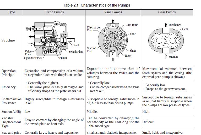
8 2 Pumps Pumps used in hydraulic systems are Positive displacement pumps. (Rotodynamic pumps like centrifugal pump are not used) Most commonly used pumps are 1. Gear Pump (External or Internal ) 2. Vane Pump 3. Piston pump (Axial Regular or Bent Axis type) These pumps deliver a constant volume of fluid in a cycle. The discharge quantity per revolution is fixed in these pumps and they produce fluid flow proportional to their displacement and rotor speed. These pumps are used in most of the industrial fluid power applications. The output fluid flow is constant and is independent of the system pressure (load). P o i n t s t o N o t e a b o u t P u m p s : Positive displacement pumps i. generate high pressures, ii. high volumetric efficiency, iii. high power to weight ratio, iv. have little change in efficiency throughout the pressure range v. have wide operating range pressure and speed. The fluid flow rate of these pumps ranges from 0.1 to 15,000 gpm, and the pressure ranges between 1 to 700 bar. Pressure is a back effect: Positive displacement pumps do not produce pressure but they only produce fluid flow. The resistance to output fluid flow generates the pressure. It means that if the discharge port (output) of a positive displacement pump is opened to the atmosphere, then fluid flow will not generate any output pressure above atmospheric pressure. But, if the discharge port is partially blocked, then the pressure will rise due to the increase in fluid flow resistance. If the discharge port of the pump is completely blocked, then an infinite resistance will be generated. This will result in the breakage of the weakest component in the circuit. Therefore, a safety valves called relief valve is invariably provided in the hydraulic circuits. 2.1 Gear Pumps Gear pump is a robust and simple positive displacement pump. It has two meshed gears revolving about their respective axes. These gears are the only moving parts in the pump. They are compact, relatively inexpensive and have few moving parts. Gear pumps are most commonly used for the hydraulic fluid power applications and are also widely used in chemical industries. 8


9 Based upon the design, the gear pumps are classified as: External gear pumps Lobe pumps Internal gear pumps Gerotor pumps 2.2 External gear pump 2.3 Lobe Pump Working: One of the two gears / lobes is connected to a motor and causes rotation of the other. As they rotate in the direction shown, vacuum is created on the inlet side, liquid is trapped between the gear teath / lobe and the motor casing. On further rotation liquid is forced to the outlet side. The gear teeth or lobes at the centre provide a seal between the inlet and outlet. 9

10 The volume displaced (d p ) is product of the area entrapped and width of tooth per each revolution and is constant. Flow rate is N x d p, where is the speed of motor. (use appropriate units) 2.4 Internal Gear Pump: Working : The internal gear is eccentric to the outer gear. Rotation of the internal gear causes suction on inlet side, liquid is trapped between internal gear teeth and the crescent seal, and is forced out to outlet port. Internal gear pumps are exceptionally versatile. They are often used for low or medium viscosity fluids such as solvents and fuel oil and wide range of temperature. This is non- pulsing, self-priming and can run dry for short periods. It is a variation of the basic gear pump. 2.5 Vane Pumps Gear pumps have a disadvantage of small leakage due to gap between gear teeth and the pump housing. This limitation is overcome in vane pumps. Working principle: The schematic of vane pump working principle is shown in figure. Vane pumps generate a pumping action by tracking of vanes along the casing wall. 10


11 The vane pumps generally consist of a rotor, vanes, ring and a port plate with inlet and outlet ports. The rotor in a vane pump is connected to the prime mover through a shaft. The vanes are located on the slotted rotor. The rotor is eccentrically placed inside a cam ring as shown in the figure. The rotor is sealed into the cam by two side plates. When the prime mover rotates the rotor, the vanes are thrown outward due to centrifugal force. The vanes track along the ring. It provides a tight hydraulic seal to the fluid which is more at the higher rotation speed due to higher centrifugal force. This produces a suction cavity in the ring as the rotor rotates. It creates vacuum at the inlet and therefore, the fluid is pushed into the pump through the inlet. The fluid is carried around to the outlet by the vanes whose retraction causes the fluid to be expelled. The capacity of the pump depends upon the eccentricity, expansion of vanes, width of vanes and speed of the rotor. It can be noted that the fluid flow will not occur when the eccentricity is zero. 2.6 Unbalanced Vane pump: In practice, the vane pumps have more than one vane as shown in figure 11

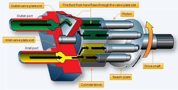
12 The rotor is offset within the housing, and the vanes are constrained by a cam ring as they cross inlet and outlet ports. Although the vane tips are held against the housing, still a small amount of leakage exists between rotor faces and body sides. This type of pump is called as unbalanced vane pump. 2.7 Balanced vane pump This pump has an elliptical cam ring with two inlet and two outlet ports. Pressure loading still occurs in the vanes but the two identical pump halves create equal but opposite forces on the rotor. It leads to the zero net force on the shaft and bearings. Thus, life of pump and bearing increase significantly. Also the sound and vibration are less. 2.8 Axial Piston Pump Balanced Vane Pump Axial piston pumps are positive displacement pumps which converts rotary motion of the input shaft into an axial reciprocating motion of the pistons. These pumps have a number of pistons (usually an odd number) in a circular array within a housing which is commonly referred to as a cylinder block, rotor or barrel. In general, these systems have a maximum operating temperature of about 120 C. Therefore, the leakage between cylinder 12

13 housing and body block is used for cooling and lubrication of the rotating parts. This cylinder block rotates by an integral shaft aligned with the pistons. There are two types of ax ial piston pumps. a. Bent axis piston pumps b. Swash plate axial piston pump 2.9.a Bent-Axis Piston Pump In these pumps, the reciprocating action of the pistons is obtained by bending the axis of the cylinder block. The cylinder block rotates at an angle which is inclined to the drive shaft. The cylinder block is turned by the drive shaft through a universal link. The cylinder block is set at an offset angle with the drive shaft. The cylinder block contains a number of pistons along its periphery. These piston rods are connected with the drive shaft flange by ball-and- socket joints. These pistons are forced in and out of their bores as the distance between the drive shaft flange and the cylinder block changes. A universal link connects the block to the drive shaft, to provide alignment and a positive drive. Bent Axis Piston pump The volumetric displacement (discharge) of the pump is controlled by changing the offset angle. 2.9.b Swash Plate Axial Piston Pump A swash plate is a device that translates the rotary motion of a shaft into the reciprocating motion. It consists of a disk attached to a shaft as shown in Figure If the disk is aligned perpendicular to the shaft; the disk will turn along with the rotating shaft without any reciprocating effect. Similarly, the edge of the inclined shaft will appear to oscillate along the shaft's length. This apparent linear motion increases with increase in the angle between disk and the shaft (offset angle). 13

14 The apparent linear motion can be converted into an actual reciprocating motion by means of a follower that does not turn with the swash plate. Swash plate piston pump In swash plate axial piston pump a series of pistons are aligned coaxially with a shaft through a swash plate to pump a fluid. The axial reciprocating motion of pistons is obtained by a swash plate that is either fixed or has variable degree of angle. As the piston barrel assembly rotates, the piston rotates around the shaft with the piston shoes in contact with the swash plate. The piston shoes follow the angled surface of the swash plate and the rotational motion of the shaft is converted into the reciprocating motion of the pistons. Pump capacity can be controlled by varying the swash plate angle with the help of a separate hydraulic cylinder. 14
15 15
16 3 DIRECTIONAL CONTROL VALVES (DCV) 3.1 Directional control valves can be classified in a number of ways: 1. According to type of construction : Poppet valves Spool valves 2. According to number of working ports : Two- way valves Three way valves Four- way valves. 3. According to number of Switching position: Two position Three - position 4. According to Actuating mechanism: Manual actuation Mechanical actuation Solenoid ( Electrical ) actuation Hydraulic ( Pilot ) actuation Pneumatic actuation Indirect actuation The designation of the directional control valve refers to the number of working ports and the number of switching positions. 16
 The figure below represents a 2 position, 4-way ( or 4- port) valve. The two rectangular blocks represent two positions of possible actuation of valve.")
17 3.2 How to read the valve schematic: Symbols: P Pressure port ( high pressure oil inlet from pump) T Tank or return port connected to tank A,B Ports connected to actuator (eg., piston side and rod side of cylinder) The figure below represents a 2 position, 4-way ( or 4- port) valve. The two rectangular blocks represent two positions of possible actuation of valve. A,B,P and T are the 4 ports of the valve connected to different components. Hence it is called a 2/4 valve. The construction or design of the valve is such that when valve is actuated to left side, as shown by arrows, pressure line from pump is connected to A side of actuator, and B side is connected to the tank. Similarly when valve is switched to second position, the right side is effective. (Now read the four symbols A,B,P,T on the four ports in right rectangle, which is effective). From the arrows it means P is connected to B and A is connected to T). 1. Check Valve: This valve allows flow from P to A., when pressure is enough to overcome the spring force acting on the ball, which is quite small. It does not allow flow in the other direction ie from A to P. The symbol for check valve is as shown. It is also called On-off or Non-return valve. The simplest type 17


18 of directional control valve is a check valve which is a two way valve because it contains two ports. These valves are also called as on-off valves because they allow the fluid flow in only in one direction and the valve is normally closed. Two way valves is usually the spool or poppet design with the poppet 2. Spool type on/ off valve: As can be seen from the figure, 3. 2-position, 3-way valve Symbol of 2/3 valve 4. Open center 3/4 DCV Position 0: A to T Position 1: P to A 18


19 5. Closed Center 3 / 4 DCV: 6. Tandem centered 3 /4 DCV 7. Two position, Four way DCV : 19

20 3.3 Actuation of Directional control valves : Directional control valves can be actuated by different methods. Manually actuated Valve: A manually actuated DCV uses muscle power to actuate the spool. Manual actuators are hand lever, push button, pedals. The following symbols show the DCV actuated manually (a) (b) Fig a & b shows the symbol of 2 / 4 DCV manually operated by hand lever to 1 and spring return to 2. In the above two symbols the DCV spool is returned by springs which push the spool back to its initial position once the operating force has stopped. Mechanical Actuation: The DCV spool can be actuated mechanically, by roller and cam, roller and plunger. The spool end contains the roller and the plunger or cam can be attached to the actuator (cylinder).. When the cylinder reaches a specific position the DCV is actuated. The roller tappet connected to the spool is pushed in by a cam or plunger and presses on the spool to shift it either to right or left reversing the direction of flow to the cylinder. A spring is often used to bring the valve to its center configuration when deactivated. Solenoid Actuated DCV: A very common way to actuate a spool valve is by using a solenoid is illustrated in the figure. When the electric coil (solenoid) is energized, it creates a magnetic force that pulls the armature into the coil. This caused the armature to push on the spool rod to move the spool of the valve.. The advantage of a solenoid valve is that the switching time is less. 20

21 Hydraulic actuation: This type actuation is usually known as pilot-actuated valve. The hydraulic pressure may be directly used on the end face of the spool. The pilot ports are located on the valve ends. Figure shows a DCV where the rate of shifting the spool from one side to another can be controlled by a needle valve. Fluid entering the pilot pressure port on the X end flows through the check valve and operates against the piston. This forces the spool to move towards the opposite position. Fluid in the Y end (right end, not shown in the figure) is passed through the adjustable needle valve and exhausted back to tank. The amount of fluid bled through the needle valve controls how fast the valve will shift. Indirect actuation of directional control valve 21


22 4 Pressure Relief Valves The pressure relief valve is used to protect the hydraulic components from excessive pressure. It is one of the most important components of a hydraulic system and is essentially required for safe operation of the system. Its primary function is to limit the system pressure within a specified range. It is normally a closed type and it opens when the pressure exceeds a specified maximum value by diverting pump flow back to the tank. The simplest type valve contains a poppet held in a seat against the spring force as shown in the figure. The fluid enters from the opposite side of the poppet. When the system pressure exceeds the preset value, the poppet lifts and the fluid is escaped through the orifice to the storage tank directly. It reduces the system pressure and as the pressure reduces to the set limit again the valve closes. This valve does not provide a flat cut-off pressure limit with flow rate because the spring must be deflected more when the flow rate is higher. Various types of pressure control valves are discussed in the following sections: 1.Pressure Relief Valve: When the system pressure exceeds a set value, the poppet raises up and allows fluid to flow rank. 2. Unloading Valve: A unloading valve is used to permit a pump to operate at minimum load. The unloading valve is normally closed valve with the spool closing the tank port. When a pilot pressure is enough to overcome the spring force, spool moves up and flow is diverted to tank. When the pilot pressure is relaxed, spool moves down and lets the flow to the circuit for operation. 22


23 The unloading valve is used in system having one or more fixed delivery pump to control the amount of flow at any given time. A well designed hydraulic circuit uses the correct amount of fluid for each phase of a given cycle of machine operations. When pressure builds up during the feed phase of the cycle, the pilot pressure opens the unloading valve, causing the large discharge pump to bypass its flow back to the tank. 3. Sequence valve: A sequence valve s primary function is to divert flow in a predetermined sequence. It is a pressure-actuated valve similar in construction to a relief valve and normally a closed valve. When the main system pressure overcomes the spring setting, the valve spool moves up allowing flow from the secondary port. 4. Counter balance Valve: A C o u n t e r balance valve is used to maintain back pressure to prevent a load from failing. One can find application in vertical presses, lift trucks, loaders and other machine tool that must position or hold suspended loads. 23
 and (b) illustrate the comparison between direct and remote pilot signal (a) (b) 5. Pressure Reducing Valve: Pressure reducing valve is used to limit its outlet pressure.")
24 When a counterbalance valve is used on large vertical presses, it may important to analyze the source of pilot pressure. Figures (a) and (b) illustrate the comparison between direct and remote pilot signal (a) (b) 5. Pressure Reducing Valve: Pressure reducing valve is used to limit its outlet pressure. Reducing valves are used for the operation of branch circuits, where pressure may be less than the main system pressure. The pressure reducing valve is normally an open type valve. When the secondary pressure is high, it lifts the spool against the spring force and throttles the flow till such extent that the secondary pressure reaches the value as set by spring. 24
25 5. SOME TYPICAL HYDRAULIC CIRCUITS 5.1 In this part we will look at some of the simple and commonly encountered hydraulic circuits. The circuits are drawn using the standard graphical symbols. 1. Control of a Single- Acting Hydraulic Cylinder In single acting cylinder hydraulic force is exerted on the piston for forward movement (to right in the figure shown). For retraction, no hydraulic force is applied and the rod moves (to left) due to a spring force or weight of the piston and rod Figure shows a two-position, three way, manually operated, spring offset directional control valve ( DCV ) used to control the operation of a single acting cylinder. As valve is moved to occupy position 1 (left) flow goes to rod end and rod is pushed to right. When valve is moved to position 0, i.e. shifted to right indicated position, flow from pump is blocked in the valve. There is no hydraulic pressure on the piston side. The flow goes to tank via relief valve at the set pressure. The actuator moves to left due to spring force acting on the rod end of piston. 2. Control of Double Acting Hydraulic Cylinder: Double Acting cylinders can be extended and retracted hydraulically. Thus, an output force can be applied in two directions. Double acting cylinder 25
26 The valve is manual 3postion /4-way valve. In the neutral or valve central (0) position, oil from pump goes to tank, and no action on actuator. Note that the valve does not go through relief valve to tank, thereby saving power (Pressure set in relief valve x pump flow rate ). There is minor power loss due to drop in valve orifices, and piping. In position 1 of valve, oil flow is P to A. ie. from pump to piston side and rod moves to right acting on the load. Oil from rod side chamber of cylinder goes to tank (B to T). In position 2, Oil from pump goes to rod end (P to B) and Oil from piston end goes to tank. (A to T) thereby pushing the rod (load) to left. 3. Regenerative circuit: Operation: Figure shows a regenerative circuit that is used to speed up the extending speed of a double-acting hydraulic cylinder. It can be seen that in position 1 when pump is connected to piston side chamber,ie., when main load is operated, fluid from piston side also flows into it. Thereby the flow rate is more than 26
27 pump flow. Thus the velocity of actuation on piston side is increased by the ratio ( A p / A r ), where A p is the piston area and A r is the rod area.. However, the net force due to the piston rod is reduced to A r x Pressure. In position 2, when flow is directed to rod side, oil from the piston side flows to tank directly. 4. Pump Unloading Circuit The figure shows a circuit using an unloading valve to unload a pump. The unloading valve opens when the cylinder reaches the end of its extension stroke because the check valve keeps high-pressure oil in the pilot line of the unloading valve. When the DCV is shifted to retract the cylinder, the motion of the piston reduces the pressure in the pilot line of the unloading valve. This resets the unloading valve until the cylinder is fully retracted, at which point the unloading valve unloads the pump. Thus, the unloading valve unloads the pump at the ends of the extending and retraction strokes as well as in the spring-centered position of the DCV. 5. Counter Balance Valve Application Counter balance valve is used to hold loads in vertical position without descending while idling in neutral position. Rod side fluid cannot flow unless a pilot pressure acts on the valve and permits flow to tank. The valve spring so set that pressure required is higher than for upward stroke. 27
28 5.2 Hydraulic Cylinder Sequencing Circuits: Figure shows an example where two sequence valves are used to control the sequence of operations of two double-acting cylinders C1 and C2. When the DCV is shifted into its left position, the left cylinder extends completely, and pressure builds up and only when the left cylinder pressure reaches the pressure setting of sequence valve, the sequence valve connected to the right cylinder opens and permits flow to rod end of C2, and extends it. If the DCV is then shifted to right position, flow to rod end of C1 is blocked, but flows freely to rod end of C2. After C2 retracts fully, pressure builds up till the valve connected to C1 opens. Thus the sequence is C1Ext - C2Ext - C2Retr C1 Retr. One can find the application of this circuit in press circuit. For example, the left cylinder the clamping cylinder C1 could extend and clamp a workpiece. Then the right cylinder C2, the punching cylinder extends to punch a hole in the workpiece. The right cylinder then retracts the punch, and then the left cylinder retracts to declamp the workpiece for removal. 28
29 5.3 Automatic Cylinder Reciprocating System (i) Using Sequence Valves Operation: In the left position of valve shown, P is connected to rod-side, and the rod retracts. After piston reaches the left end, pressure builds up on rod side which opens the sequence valve on the right and permits pilot hydraulic line to act on the main DCV to switch to right position. Check valves allow pilot oil to leave either end of the DCV while pilot pressure is applied to the opposite end. (ii) An alternative circuit is shown using limit switches and solenoid valve, and a pilot operated DCV.. Operation: Suppose the left position of the main DCV is on. Then the piston rod moves to right > It hits the limit switch 2 > which energises solenoid valve D2 > which shifts the solenoid operated DCV (D2) to position (top as shown) > which now permits pilot oil from D2 to right end of DCV D1 > changes D1 position 2 > flow is now to rod end > rod moves to left till it hits limit switch 1. Now the reverse of the above sequence is repeated so that Position 1 of the main DCV becomes operative. Thus it leads to automatic reciprocation of the actuator between the limit switch positions. 29
30 5.4 Cylinder Synchronizing Circuits : Circuits are shown for synchronising the operation of two cylinders (ie simultaneous equal movement). a. Cylinder connected in Parallel In the circuit shown, piston or rod ends of both cylinders are connected to one line. Thus oil flows simultaneously. However, if load on one cylinder is more, the other cylinder needing less pressure operates first, and after completion of stroke, pressure builds up to operate the second cylinder. This operation is not synchronised. The problem may arise with slight differences in the size of cylinders as well. b. Cylinders connected in Series: The rod end of C1 is connected to piston end of C2. Thus C1 and C2 have to move together. However, for to have equal stroke, rod end area of C1 should be equal to piston area of C1. Also, rod end of C2 has to have high pressure to do work by C2. Hence piston side pressure would be that much higher. 30
31 5.5 Speed Control Speed control of Hydraulic Cylinder: Speed control of a hydraulic cylinder is accomplished using a flow control valve. A flow control valve regulates the speed of the cylinder by controlling the flow rate to and of the actuator. There are 3 types of speed control: Meter-in circuit ( Primary control ) Meter-out circuit ( Secondary control ) Bleed -off circuit ( By pass control ) 1. Meter in Circuit : In this type of speed control, the flow control valve is placed between the pump and the actuator. Thereby, it controls the amount of fluid going into the actuator. Figure below shows meter-in circuit. When the direction is reversed, oil from piston side flows to tank via check valve as well as FC valve freely. The excess flow is dumped to tank via relief valve. 2. Meter out Circuit : In this type of speed control, the flow control valve is placed between the actuator and the tank. Thereby, it controls the amount of fluid going out of the actuator and thereby the speed of retraction. Meter out circuits are useful to control free fall of loads due to gravity etc. connected to the load. Oil is dumped at load pressure but not at relief valve set pressure. However, meter out can lead to high pressure intensification sometimes twice supply pressure, leading to damage of seals etc. Still it is favoured in drilling, reaming and milling when it is required to control the tool feed rate. 31
32 3. Bleed off circuit: This circuit is used to overcome the disadvantages of meter-in and meterout circuits. Here, a flow control valve is kept between either ends. Flow is controlled in each direction, and excess flow to tank is not through relief valve. 32

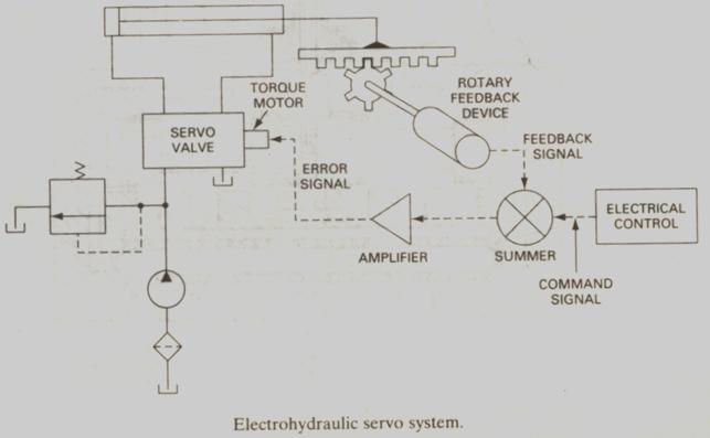
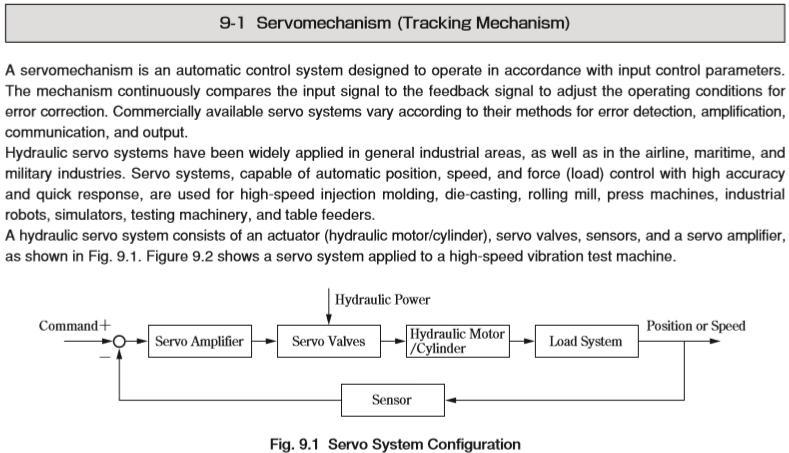
33 6. Hydraulic Servo Systems: Servo systems refer to systems where automatic control of actuator movements is required. These movements should be as per a predetermined rate and deviations should be reduced to a minimum. A servomechanism is an automatic control system designed to operate in accordance with input control parameters. The mechanism continuously compares the input signal to the feedback signal to adjust the operating conditions to correct error. Applications: Hydraulic servo systems are widely used in the airline, maritime, and military applications. Servo systems capable of automatic position, speed, force control with high accuracy are used in high-speed injection moulding, die casting, rolling mills, presses, industrial robots, flight simulators testing machinery and table feeders. For achieving automation, a feedback signal, using a sensor, from the actuator or any variable to be controlled such as actuator force or velocity or displacement or angle of rotation of a rotary actuator is required. This feedback signal is compared with the reference input and a suitably modified signal is sent to the flow control valve to thereby control the required variable. A block diagram representation of a hydraulic servo system is shown below. 33
 for certain flow rate. 2. The flow actuates the piston and the load to left. 3.")
34 6.1 A Mechanical servo system: In this sytem shown in the figure, load is connected to the valve spool, and special sensors and electrical components are not required. Operation: 1. Input movement to the valve opens the spool (to left) for certain flow rate. 2. The flow actuates the piston and the load to left. 3. The load, being connected to the valve body, also moves to left, while the spool is in the same postion. 4. Thus the opening of spool is gradually reduced as the piston moves. When the piston moves by the distance of initial spool movement, spool closse the port opening and flow becomes zero. 5. Thus Input movement of spool is related to the load movement. 6. Thus this arrangement provides a feed back signal. A separate link can be connected to valve spool, cylinder rod and the input, to achieve a ratio of output/ input other than 1. 34
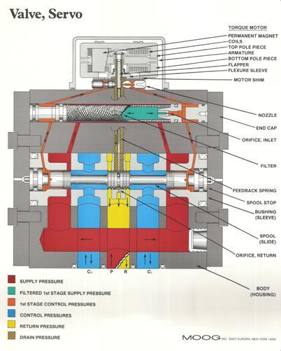
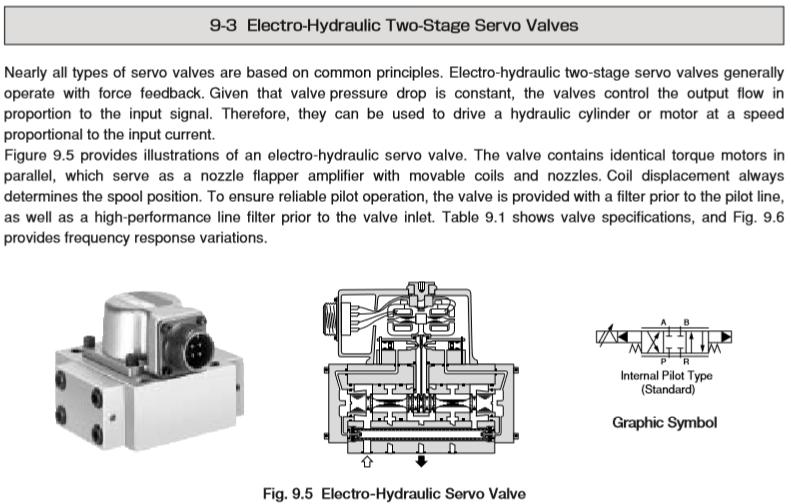
35 6.2 Proportional type valves: Valves explained so far are on-off type, ie, they take distinctly one of the two or three positions letting full flow in either direction or stop the flow. However for servo systems valves which operate in an analog fashion, ie continuously variable control are required. Special valves: In view of the continuous control, special proportional control valves are used which produce movement of the spool proportional to an electrical signal. The signal given to the valve is the error signal (difference between the reference input and that sensed by the actuator), so that the system corrects to make the error zero, or actuator achieves the desired parameter Electrohydraulic Servo System: For highly accurate control as in aerospace systems and some machine tools, a two- stage electrohydraulic servo valve is used. (shown in figure) In this valve, an electrical input signal operates a torque moto r, which turns a flapper which runs between two nozzles > which varies the back pressures at two nozzles > backpressures act at either end of the main spool > which moves the spool and lets certain flow > which in turn moves the flapper at the nozzles in opposite direction to that produced by torque motor > which in turn changes the feedback pressures acting on spool > spool keeps on moving this way till flapper comes to the middle of nozzles, when the back pressures acting on spool are equal > spool movement stops. With the above sequence of operations, it can be seen that magnitude of spool movement or of the corresponding flow is related to the input current or voltage signal to the servo valve. These valves are highly accurate but cost can be very high ranging from Rs. 3 to Rs. 10 lakhs and higher. 35
36 36
37 37
38 38
CH.4 Basic Components of Hydraulic and Pneumatic System/16 M HAP/17522/AE5G
 Content : 4.1 Hydraulic and Pneumatic actuators. 10 Marks Hydraulic Actuators - Hydraulic cylinders (single, double acting and telescopic) construction and working, Hydraulic motors (gear and piston type)
Test Which component has the highest Energy Density? A. Accumulator. B. Battery. C. Capacitor. D. Spring.
 Test 1 1. Which statement is True? A. Pneumatic systems are more suitable than hydraulic systems to drive powerful machines. B. Mechanical systems transfer energy for longer distances than hydraulic systems.
Topic 1. Basics of Oil Hydraulic Systems
 Topic 1. Basics of Oil Hydraulic Systems Fluid power Fluid power is the technology that deals with the generation, control and transmission of forces and movement of mechanical element or system with the
2. Hydraulic Valves, Actuators and Accessories. 24 Marks
 2. Hydraulic Valves, Actuators and Accessories 24 Marks Co related to chapter 602.2 Describe working principle of various components used in hydraulic & pneumatic systems. 602.3 Choose valves, actuators
INTRODUCTION: Rotary pumps are positive displacement pumps. The rate of flow (discharge) of rotary pump remains constant irrespective of the
 of rotary pump remains constant irrespective of the") INTRODUCTION: Rotary pumps are positive displacement pumps. The rate of flow (discharge) of rotary pump remains constant irrespective of the pressure. That is, even at very high pressure, these pumps can
INTRODUCTION: Rotary pumps are positive displacement pumps. The rate of flow (discharge) of rotary pump remains constant irrespective of the pressure. That is, even at very high pressure, these pumps can
Hydraulic Pumps Classification of Pumps
 Fluidsys Training Centre, Bangalore offers an extensive range of skill-based and industry-relevant courses in the field of Pneumatics and Hydraulics. For more details, please visit the website: https://fluidsys.org
Module 5: Valves. CDX Diesel Hydraulics. Terms and Definitions. Categories of Valves. Types of Pressure Control Valves
 Terms and Definitions Categories of Valves Types of Pressure Control Valves Types and Operation of Pressure Relief Valves Operation of an Unloading Valve Operation of a Sequencing Valve Operation of a
Describe the function of a hydraulic power unit
 Chapter 7 Source of Hydraulic Power Power Units and Pumps 1 Objectives Describe the function of a hydraulic power unit and identify its primary components. Explain the purpose of a pump in a hydraulic
CLOSED CIRCUIT HYDROSTATIC TRANSMISSION
 Energy conservation and other advantages in Mobile Equipment Through CLOSED CIRCUIT HYDROSTATIC TRANSMISSION C. Ramakantha Murthy Technical Consultant Various features/advantages of HST Hydrostatic transmissions
Marine Engineering Exam Resource Review of Hydraulics
 1. What is Pascal s law? Pressure confined on a confined fluid will transmit the pressure in all directions and act with equal force on all areas at right angles. 2. How does the law pertain to hydraulics?
Definitions of Technical Terms
 Definitions of Technical Terms ABSOLUTE A measure having as it s zero point of base the complete absence of the entity being measured. ABSOLUTE PRESSURE A pressure scale with zero point at a perfect vacuum.
A pump is a machine used to move liquid through a piping system and to raise the pressure of the liquid.
 What is a pump A pump is a machine used to move liquid through a piping system and to raise the pressure of the liquid. Why increase a liquid s pressure? Static elevation a liquid s pressure must be increased
speed hydraulic motors. Permission granted to reproduce for educational use only. Contrast the operation of fixed- and variable-
 Chapter 9 Actuators Workhorses of the System 1 Objectives Describe the construction and operation of basic hydraulic cylinders, limited-rotation actuators, and motors. Compare the design and operation
Design and Fabrication of Sequencing Circuit with Single Double Acting Cylinder
 Design and Fabrication of Sequencing Circuit with Single Double Acting Cylinder V.G.Vijaya Department of Mechatronics Engineering, Bharath University, Chennai 600073, India ABSTRACT: This project deals
MODULE- 5 : INTRODUCTION TO HYDROSTATIC UNITS (PUMPS AND MOTORS)
") MODULE- 5 : INTRODUCTION TO HYDROSTATIC UNITS (PUMPS AND MOTORS) LECTURE- 18 : BASIC FEATURES OF SOME Hydraulic Pumps & Motors Introduction In this section we shall discuss the working principles and fundamental
MODULE- 5 : INTRODUCTION TO HYDROSTATIC UNITS (PUMPS AND MOTORS) LECTURE- 18 : BASIC FEATURES OF SOME Hydraulic Pumps & Motors Introduction In this section we shall discuss the working principles and fundamental
three different ways, so it is important to be aware of how flow is to be specified
 Flow-control valves Flow-control valves include simple s to sophisticated closed-loop electrohydraulic valves that automatically adjust to variations in pressure and temperature. The purpose of flow control
LECTURE-23: Basic concept of Hydro-Static Transmission (HST) Systems
 Systems") MODULE-6 : HYDROSTATIC TRANSMISSION SYSTEMS LECTURE-23: Basic concept of Hydro-Static Transmission (HST) Systems 1. INTRODUCTION The need for large power transmissions in tight space and their control
MODULE-6 : HYDROSTATIC TRANSMISSION SYSTEMS LECTURE-23: Basic concept of Hydro-Static Transmission (HST) Systems 1. INTRODUCTION The need for large power transmissions in tight space and their control
Experiments on Hydraulic and Pneumatic circuit trainers HYDRAULIC CIRCUITS:
 Experiments on Hydraulic and Pneumatic circuit trainers HYDRAULIC CIRCUITS: Hydraulic circuits are used in high power and high load applications such as earth moving equipment. The pressure used in industrial
Attention is drawn to the following places, which may be of interest for search:
 CPC - F04B - 2017.08 F04B POSITIVE DISPLACEMENT MACHINES FOR LIQUIDS; PUMPS (machines for liquids, or pumps, of rotary piston or oscillating piston type F04C; non-positive displacement pumps F04D; pumping
Lesson 5: Directional Control Valves
 : Directional Control Valves Basic Hydraulic Systems Hydraulic Fluids Hydraulic Tank Hydraulic Pumps and Motors Pressure Control Valves Directional Control Valves Flow Control Valves Cylinders : Directional
Lecture 6. Systems review exercise To be posted this weekend Due next Friday (3/6)
") 150 Systems review exercise To be posted this weekend Due next Friday (3/6) Lecture 6 Coming week: Lab 13: Hydraulic Power Steering Lab 14: Integrated Lab (Hydraulic test bench) Topics today: Pumps and
150 Systems review exercise To be posted this weekend Due next Friday (3/6) Lecture 6 Coming week: Lab 13: Hydraulic Power Steering Lab 14: Integrated Lab (Hydraulic test bench) Topics today: Pumps and
Nomenclature... xi Hydraulic Laws, Theorems, and Equations...xii
 Nomenclature... xi Hydraulic Laws, Theorems, and Equations...xii 1 Introduction 1.1 Component Design Perspective...1 1.2 Hydraulic Power Evolution...2 1.3 Hydraulic Applications...6 1.4 Component Design
Lecture 25 HYDRAULIC CIRCUIT DESIGN AND ANALYSIS [CONTINUED]
![Lecture 25 HYDRAULIC CIRCUIT DESIGN AND ANALYSIS [CONTINUED]](/thumbs/92/110490177.jpg "Lecture 25 HYDRAULIC CIRCUIT DESIGN AND ANALYSIS [CONTINUED]") Lecture 5 HYDRAULIC CIRCUIT DESIGN AND ANALYSIS [CONTINUED] 1.1 Circuit for Fast Approach and Slow Die Closing A machine intended for high volume production has a high piston velocity. If not controlled,
Lecture 5 HYDRAULIC CIRCUIT DESIGN AND ANALYSIS [CONTINUED] 1.1 Circuit for Fast Approach and Slow Die Closing A machine intended for high volume production has a high piston velocity. If not controlled,
LogSplitterPlans.Com
 Hydraulic Pump Basics LogSplitterPlans.Com Hydraulic Pump Purpose : Provide the Flow needed to transmit power from a prime mover to a hydraulic actuator. Hydraulic Pump Basics Types of Hydraulic Pumps
application and are used in chemical injection systems (water
 Mechanical Equipment - Course 430.1 POSITIVE DISPLACEMENT PUMPS In the previous lesson it was explained that although centrifugal pumps have many operational and maintenance adva.ntages over positive displacement
Lecture 6. This week: Lab 13: Hydraulic Power Steering [ Lab 14: Integrated Lab (Hydraulic test bench) ]
![Lecture 6. This week: Lab 13: Hydraulic Power Steering [ Lab 14: Integrated Lab (Hydraulic test bench) ]](/thumbs/84/91055223.jpg "Lecture 6. This week: Lab 13: Hydraulic Power Steering [ Lab 14: Integrated Lab (Hydraulic test bench) ]") 133 Lecture 6 This week: Lab 13: Hydraulic Power Steering [ Lab 14: Integrated Lab (Hydraulic test bench) ] 4-way directional control valve; proportional valve; servo-valve Modeling / Analysis of a servo-valve
133 Lecture 6 This week: Lab 13: Hydraulic Power Steering [ Lab 14: Integrated Lab (Hydraulic test bench) ] 4-way directional control valve; proportional valve; servo-valve Modeling / Analysis of a servo-valve
Input, Control and Processing elements
 PNEUMATIC & HYDRAULIC SYSTEMS CHAPTER FIVE Input, Control and Processing elements Dr. Ibrahim Naimi Valves The function of valves is to control the fluid path or the pressure or the flow rate. Depending
Syslog Technologies Innovative Thoughts
 AUTOMATIC PNEUMATIC WATER PUMPING SYSTEM SYNOPSIS The aim of the project is pneumatic operated water pumping system. Radial plunger Pneumatic Water pumping system are reciprocating pump in which the piston
Job Sheet 1 Introduction to Fluid Power
 Job Sheet 1 Introduction to Fluid Power Fluid Power Basics Fluid power relies on a hydraulic system to transfer energy from a prime mover, or input power source, to an actuator, or output device (Figure
TECHNICAL PAPER 1002 FT. WORTH, TEXAS REPORT X ORDER
 I. REFERENCE: 1 30 [1] Snow Engineering Co. Drawing 80504 Sheet 21, Hydraulic Schematic [2] Snow Engineering Co. Drawing 60445, Sheet 21 Control Logic Flow Chart [3] Snow Engineering Co. Drawing 80577,
Instructor Training Manual. Chapter 6 HYDRAULICS & PNEUMATICS
 Instructor Training Manual Chapter 6 HYDRAULICS & PNEUMATICS Learning Objectives 1. The purpose of this chapter is to provide a basic introduction to the principles of hydraulics & pneumatics and their
I) Clamping the work piece II) Drilling the work piece. III) Unclamping the work piece. 10
 Clamping the work piece II) Drilling the work piece. III) Unclamping the work piece. 10") Seventh Semester B.E. III IA Test, 2014 USN 1 P E M E PES INSTITUTE OF TECHNOLOGY (Bangalore South Campus) (Hosur Road, 1KM before Electronic City, Bangalore-560 100) Department of Mechanical Engineering
Seventh Semester B.E. III IA Test, 2014 USN 1 P E M E PES INSTITUTE OF TECHNOLOGY (Bangalore South Campus) (Hosur Road, 1KM before Electronic City, Bangalore-560 100) Department of Mechanical Engineering
Design and Modeling of Fluid Power Systems ME 597/ABE 591
 Systems ME 597/ABE 591 Dr. Monika Ivantysynova MAHA Professor Flud Power Systems MAHA Fluid Power Research Center Purdue University Systems Dr. Monika Ivantysynova, Maha Professor Fluid Power Systems Mivantys@purdue.edu
Al- Ameen Engg. College. Fluid Machines. Prepared by: AREEF A AP/ ME AL AMEEN ENGINEERING COLLEGE Shoranur.
 Fluid Machines Prepared by: AREEF A AP/ ME AL AMEEN ENGINEERING COLLEGE Shoranur Classification of hydraulic machines HYDROULIC MACHINES (I) Hydraulic Turbines A hydraulic machine which converts hydraulic
ESCONDIDO FIRE DEPT TRAINING MANUAL Section DRIVER OPERATOR Page 1 of 13 Pumps and Accessory Equipment Revised
 DRIVER OPERATOR Page 1 of 13 PUMPS AND ACCESSORY EQUIPMENT Pumps are designed for many different purposes. In order to understand the proper application and operation of a pump in a given situation, firefighters
FLUID POWER TUTORIAL HYDRAULIC PUMPS APPLIED PNEUMATICS AND HYDRAULICS H1
 FLUID POWER TUTORIAL HYDRAULIC PUMPS This work covers outcome 2 of the Edexcel standard module: APPLIED PNEUMATICS AND HYDRAULICS H1 The material needed for outcome 2 is very extensive so the tutorial
FIXED DISPLACEMENT HYDRAULIC VANE PUMPS SERIE BQ
 FIXED DISPLACEMENT HYDRAULIC VANE PUMPS SERIE BQ BQ FIXED DISPLACEMENT HYDRAULIC VANE PUMPS BQ SERIES Versatility, power, compactness and low running costs are the main characteristics of B&C vane pumps.
CH.6 Hydraulic and Pneumatic Circuits/20M. 6.1 Hydraulic Circuits
 Content : 6.1 Hydraulic Circuits 10 Marks Hydraulic symbols Meter in, Meter out. Bleed off, Sequencing. Introduction to electro-hydraulics concept, principles and applications Applications of hydraulic
FIXED DISPLACEMENT HYDRAULIC VANE PUMPS SERIE BQ
 FIXED DISPLACEMENT HYDRAULIC VANE PUMPS SERIE BQ BQ FIXED DISPLACEMENT HYDRAULIC VANE PUMPS BQ SERIES Versatility, power, compactness and low running costs are the main characteristics of B&C vane pumps.
FRL unit consist of Filterations, Regulators and Lubricator unit.
 4.1 AIR CONTROL 4.1.1 Fluid Conditioner FRL unit consist of Filterations, Regulators and Lubricator unit. It is also known as Air Service Unit. Primary function is to provide clean air at optimal pressure
CL2-B INSTRUCTION BOOKLET CONTENTS
 CONTENTS PAGE SUBJECT 1 Contents 2 Health & Safety Notice 3 Operating instructions 3 Extracting Old Rivets & Hints of Extracting 4 5 Clinching New Rivets & tooling selection 6 Anvil Height Adjustment 7
LESSON 2 BASIC CONSTRUCTION AND OPERATION OF HYDRAULIC ACTUATING DEVICES, FLOW CONTROL, AND DIRECTIONAL DEVICES. STP Tasks:
 LESSON 2 BASIC CONSTRUCTION AND OPERATION OF HYDRAULIC ACTUATING DEVICES, FLOW CONTROL, AND DIRECTIONAL DEVICES STP Tasks: 552-758-1003 552-758-1071 OVERVIEW LESSON DESCRIPTION: In this lesson you will
Linear Shaft Motors in Parallel Applications
 Linear Shaft Motors in Parallel Applications Nippon Pulse s Linear Shaft Motor (LSM) has been successfully used in parallel motor applications. Parallel applications are ones in which there are two or
Module 13: Mechanical Fuel Injection Diagnosis and Repair
 Terms and Definitions Parts of Injection Nozzles Types of Nozzle Valves Operation of an Injection Nozzle Fuel Flow Through the Unit Injector Optional Features on Fuel Injection Pumps Main Parts of a Distributor-Type
Chapter B-3. Chapter 3. Actuators and output devices. Festo Didactic TP101
 155 Chapter 3 Actuators and output devices Festo Didactic TP101 156 An actuator is an output device for the conversion of supply energy into useful work. The output signal is controlled by the control
Note 8. Electric Actuators
 Note 8 Electric Actuators Department of Mechanical Engineering, University Of Saskatchewan, 57 Campus Drive, Saskatoon, SK S7N 5A9, Canada 1 1. Introduction In a typical closed-loop, or feedback, control
Lecture 6. Systems review exercise To be posted this afternoon Due in class (10/23/15)
") 153 Systems review exercise To be posted this afternoon Due in class (10/23/15) Lecture 6 Coming week: Lab 13: Hydraulic Power Steering Lab 14: Integrated Lab (Hydraulic test bench) Topics today: 2 min
153 Systems review exercise To be posted this afternoon Due in class (10/23/15) Lecture 6 Coming week: Lab 13: Hydraulic Power Steering Lab 14: Integrated Lab (Hydraulic test bench) Topics today: 2 min
Introduction. General Information. Systems Operation
 Systems Operation Introduction Reference: For illustrated Specifications, refer to the Specifications For 416, 426, 428, 436, 438, & Series II Backhoe Loaders Transmission, Form No. SENR3131. If the specifications
Hydraulic energy control, conductive part
 Chapter 2 2 Hydraulic energy control, conductive part Chapter 2 Hydraulic energy control, conductive part To get the hydraulic energy generated by the hydraulic pump to the actuator, cylinder or hydraulic
COOPERATIVE PATENT CLASSIFICATION
 CPC F COOPERATIVE PATENT CLASSIFICATION MECHANICAL ENGINEERING; LIGHTING; HEATING; WEAPONS; BLASTING (NOTE omitted) ENGINES OR PUMPS F01 MACHINES OR ENGINES IN GENERAL (combustion engines F02; machines
Hydrostatic Drive. 1. Main Pump. Hydrostatic Drive
 Hydrostatic Drive The Hydrostatic drive is used to drive a hydraulic motor at variable speed. A bi-directional, variable displacement pump controls the direction and speed of the hydraulic motor. This
To study the constructional features of ammeter, voltmeter, wattmeter and energymeter.
 Experiment o. 1 AME OF THE EXPERIMET To study the constructional features of ammeter, voltmeter, wattmeter and energymeter. OBJECTIVE 1. To be conversant with the constructional detail and working of common
TPV Variable Displacement Closed Loop System Axial Piston Pump THE PRODUCTION LINE OF HANSA-TMP HT 16 / M / 852 / 0815 / E
 HYDRAULIC COMPONENTS HYDROSTATIC TRANSMISSIONS GEARBOXES - ACCESSORIES Certified Company ISO 9001-14001 ISO 9001 Via M. L. King, 6-41122 MODENA (ITALY) Tel: +39 059 415 711 Fax: +39 059 415 729 / 059 415
TPCT S. College of Engineering, Osmanabad. Laboratory Manual. Industrial Hydraulics and Pneumatics. For. Third Year Students. Manual Prepared by
 TPCT S College of Engineering, Osmanabad Laboratory Manual Industrial Hydraulics and Pneumatics For Third Year Students Manual Prepared by C.G. Nhavkar Author COE, Osmanabad. 1 TPCT S College of Engineering,
LECTURE 24 TO 26 - HYDRAULIC CIRCUIT DESIGN FREQUENTLY ASKED QUESTIONS
 LECUE 24 O 26 - HYDAULIC CICUI DESIGN EQUENLY ASKED QUESIONS 1. List three important considerations to be taken into account while designing a hydraulic circuit here are 3 important considerations in designing
Infinitely Variable Capacity Control
 Purdue University Purdue e-pubs International Compressor Engineering Conference School of Mechanical Engineering 1972 Infinitely Variable Capacity Control K. H. White Ingersoll-Rand Company Follow this
Check Valves Check Valves are the simplest form of directional control valves, but they can also be used as pressure controls.
 Check Valves Check Valves are the simplest form of directional control valves, but they can also be used as pressure controls. Standard Check Valve The standard check valve permits free flow in one direction
Driving Characteristics of Cylindrical Linear Synchronous Motor. Motor. 1. Introduction. 2. Configuration of Cylindrical Linear Synchronous 1 / 5
 1 / 5 SANYO DENKI TECHNICAL REPORT No.8 November-1999 General Theses Driving Characteristics of Cylindrical Linear Synchronous Motor Kazuhiro Makiuchi Satoshi Sugita Kenichi Fujisawa Yoshitomo Murayama
TILLOTSON LTD., CLASH INDUSTRIAL ESTATE, TRALEE, CO. KERRY, IRELAND PHONE: FAX:
 TILLOTSON LTD., CLASH INDUSTRIAL ESTATE, TRALEE, CO. KERRY, IRELAND PHONE: +353 66 7121911 FAX: +353 66 7124503 e-mail: sales@tillotson.ie SERIES SERVICE MANUAL INTRODUCTION The gasoline engine industry
Section 6.1. Implement Circuit - General System. General: TF Configuration TB Configurations Implement Control Valve:
 Section 6.1 Implement Circuit - General System General: TF Configuration... 6.1.3 TB Configurations... 6.1.5 Implement Pump Breakdown... 6.1.6 Operational Description: General... 6.1.7 Compensator Control...
Starting up hydraulic systems
 General / Installation A hydraulic system that operates economically, safely, and trouble-free requires careful planning, as well as proper installation and start-up. Conscientious maintenance has a considerable
HYDRAULIC VARIABLE PUMPS
 HYDRAULIC VARIABLE S EFFICIENT VARIABLE DELIVERY Checkball pump delivery is controlled by variable inlet ports in each piston pumping chamber. In these hydraulic variable models, output is regulated by
Project Manual Industrial Hydraulics
 Electric Drives and Controls Hydraulics Linear Motion and Assembly Technologies Pneumatics Service Project Manual Industrial Hydraulics RE 00845/04.07 Trainer s manual Electric Drives and Controls Hydraulics
ENGINE & WORKING PRINCIPLES
 ENGINE & WORKING PRINCIPLES A heat engine is a machine, which converts heat energy into mechanical energy. The combustion of fuel such as coal, petrol, diesel generates heat. This heat is supplied to a
Servo and Proportional Valves
 Servo and Proportional Valves Servo and proportional valves are used to precisely control the position or speed of an actuator. The valves are different internally but perform the same function. A servo
What does pressure refer to in relation to hydrostatics and what is it dependent on?
 Question 1 [3 Marks] What does pressure refer to in relation to hydrostatics and what is it dependent on? Question 2 [14 Marks] Make a circuit diagram of a regular hydraulic plant that is used to control
CENTAC Inlet and Bypass Valve Positioners
 CENTAC Inlet and Bypass Valve Positioners INGERSOLL-RAND AIR COMPRESSORS INLET AND BYPASS VALVE POSITIONERS Copyright Notice Copyright 1992, 1999 Ingersoll-Rand Company THIS CONTENTS OF THIS MANUAL ARE
WINTER 14 EXAMINATION Subject Code: Model Answer Page No: 1/20
 Subject Code: 17522 Model Answer Page No: 1/20 Important Instructions to examiners: 1) The answers should be examined by key words and not as word-to-word as given in the model answer scheme. 2) The model
Module 6 Assignment Part A
 Module 6 Assignment Part A TOTAL MARKS Part A = 192 TOTAL QUESTIONS Part A = 36 Question 1 [3 Marks] What does pressure refer to in relation to hydrostatics and what is it dependent on? Question 2 [14
GoTo Europe Focused Delivery Program. Product overview Industrial and Mobile Hydraulics
 GoTo Europe Focused Delivery Program Product overview Industrial and Mobile Hydraulics 2 GoTo Europe You have hardly any time to complete your order before your delivery arrives Nowadays, every day counts
VALVE TIMING DIAGRAM FOR SI ENGINE VALVE TIMING DIAGRAM FOR CI ENGINE
 VALVE TIMING DIAGRAM FOR SI ENGINE VALVE TIMING DIAGRAM FOR CI ENGINE Page 1 of 13 EFFECT OF VALVE TIMING DIAGRAM ON VOLUMETRIC EFFICIENCY: Qu. 1:Why Inlet valve is closed after the Bottom Dead Centre
Fixed Displacement Gear Pumps
 Fixed Displacement Gear Pumps D/H/HD Series Introduction Series D/H/HD Features Pressure-loaded design Efficient, simple design - few moving parts Exceptionally compact and lightweight for their capacity
2006 MINI Cooper S GENINFO Starting - Overview - MINI
 MINI STARTING SYSTEM * PLEASE READ THIS FIRST * 2002-07 GENINFO Starting - Overview - MINI For information on starter removal and installation, see the following articles. For Cooper, see STARTER WITH
FIXED DISPLACEMENT HYDRAULIC VANE PUMPS SERIE BV
 FIXED DISPLACEMENT HYDRAULIC VANE PUMPS SERIE BV BV FIXED DISPLACEMENT HYDRAULIC VANE PUMPS BV SERIES Versatility, power, compactness and low running costs are the main characteristics of B&C vane pumps.
FIXED DISPLACEMENT HYDRAULIC VANE PUMPS BV SERIES
 BV FIXED DISPLACEMENT HYDRAULIC VANE PUMPS BV SERIES Versatility, power, compactness and low running costs are the main characteristics of B&C vane pumps. All the components subject to wear are contained
GPM Hydraulic Consulting, Inc. P.O. Box 689. Social Circle, GA Hydraulic Consulting, Inc
 Hydraulic Consulting, Inc This special promotional CD is to demonstrate how your hydraulic troubleshooting manual can be ordered as an Adobe Acrobat ebook. It can be installed on any computer with the
Chapter 33 Fundamentals of Hydraulic and Air-Over-Hydraulic Braking Systems
 Chapter 33 Fundamentals of Hydraulic and Air-Over-Hydraulic Braking Systems Introduction Vehicle s braking system must meet the following requirements: To adequately and safely reduce a vehicle s speed,
CHITKARA UNIVERSITY. (LECTURE NOTES SERIES FOR DR. REDDY Labs BADDI) Er. Anoop Aggarwal (Associate Professor, Deptt. Of Mechanical Engineering)
 Er. Anoop Aggarwal (Associate Professor, Deptt. Of Mechanical Engineering)") BASIC HYDRAULICS (LECTURE NOTES SERIES FOR DR. REDDY Labs BADDI) Er. Anoop Aggarwal (Associate Professor, Deptt. Of Mechanical Engineering) CHITKARA UNIVERSITY Er. GAUTAM MALIK Fluid Power Machine Hydraulic
BASIC HYDRAULICS (LECTURE NOTES SERIES FOR DR. REDDY Labs BADDI) Er. Anoop Aggarwal (Associate Professor, Deptt. Of Mechanical Engineering) CHITKARA UNIVERSITY Er. GAUTAM MALIK Fluid Power Machine Hydraulic
DESCRIPTION & OPERATION
 DESCRIPTION & OPERATION BRAKE BOOSTER Delco-Moraine Single Diaphragm A combined vacuum-hydraulic unit which uses a combination of intake manifold vacuum and atmospheric pressure to provide power assist.
DISCUSSION OF FUNDAMENTALS. A hydraulic system can be controlled either manually or automatically:
 Unit 1 Introduction to Electrical Control of Hydraulic Systems UNIT OBJECTIVE When you have completed this unit, you will be able to identify the components used for electrical control of the Hydraulics
Pneumatic & Hydraulic SYSTEMS
 Pneumatic & Hydraulic SYSTEMS CHAPTER EIGHT HYDRAULIC PUMPS AND ACTUATORS Dr. Ibrahim Naimi The higher the discharge pressure, the lower the volumetric efficiency because internal leakage
AN EXPLANATION OF CIRCUITS CARTER YH HORIZONTAL CLIMATIC CONTROL CARBURETER
 AN EXPLANATION OF CIRCUITS CARTER YH HORIZONTAL CLIMATIC CONTROL CARBURETER The Carter Model YH carbureter may be compared with a Carter YF downdraft carbureter with the circuits rearranged to operate
Basic Instruments Introduction Classification of instruments Operating principles Essential features of measuring
 Basic Instruments www.worldwebsites8.blogspot.com Introduction Classification of instruments Operating principles Essential features of measuring instruments PMMC Instruments Moving Iron instruments Introduction
SAMPLE STUDY MATERIAL
 IC Engine - ME GATE, IES, PSU 1 SAMPLE STUDY MATERIAL Mechanical Engineering ME Postal Correspondence Course Internal Combustion Engine GATE, IES & PSUs IC Engine - ME GATE, IES, PSU 2 C O N T E N T 1.
Moments. It doesn t fall because of the presence of a counter balance weight on the right-hand side. The boom is therefore balanced.
 Moments The crane in the image below looks unstable, as though it should topple over. There appears to be too much of the boom on the left-hand side of the tower. It doesn t fall because of the presence
Driver Driven. InputSpeed. Gears
 Gears Gears are toothed wheels designed to transmit rotary motion and power from one part of a mechanism to another. They are fitted to shafts with special devices called keys (or splines) that ensure
Track Drive Circuit - General System. Simplified Travel Circuit Diagrams: Neutral Controls Forward Travel Reverse Travel
 Section 7.1 Track Drive Circuit - General System Simplified Travel Circuit Diagrams: Neutral Controls... 7.1.2 Forward Travel... 7.1.4 Reverse Travel... 7.1.5 General... 7.1.3 Track Drive Circuit: General...
walton TEMPERATURE CONTROL SYSTEMS Pneumatically Operated (Rotary)
") walton TEMPERATURE CONTROL SYSTEMS Pneumatically Operated (Rotary) WALTON ENGINEERING CO. LTD. 61 London Road St Albans Hertfordshire AL1 1LJ England Telephone +44 (0)1727 855616 Fax +44 (0)1727 841145
walton TEMPERATURE CONTROL SYSTEMS Pneumatically Operated (Rotary) WALTON ENGINEERING CO. LTD. 61 London Road St Albans Hertfordshire AL1 1LJ England Telephone +44 (0)1727 855616 Fax +44 (0)1727 841145
Projekthandbuch. Project Manual Industriehydraulik. Industrial Hydraulics RE 00846/ Trainee's manual. Schülerhandbuch
 Electric Drives and Controls Hydraulics Linear Motion and Assembly Technologies Pneumatics Service Projekthandbuch Project Manual Industriehydraulik Industrial Hydraulics RE 00846/04.07 Schülerhandbuch
TILLOTSON LTD., CLASH INDUSTRIAL ESTATE, TRALEE, CO. KERRY, IRELAND PHONE: FAX:
 TILLOTSON LTD., CLASH INDUSTRIAL ESTATE, TRALEE, CO. KERRY, IRELAND PHONE: +353 66 7121911 FAX: +353 66 7124503 e-mail: sales@tillotson.ie HR SERIES SERVICE MANUAL INTRODUCTION Tillotson has developed
A Practical Guide to Free Energy Devices
 A Practical Guide to Free Energy Devices Part PatD20: Last updated: 26th September 2006 Author: Patrick J. Kelly This patent covers a device which is claimed to have a greater output power than the input
Modern Auto Tech Study Guide Chapters 71 & 73 Pages Brake Systems 49 Points. Automotive Service
 Modern Auto Tech Study Guide Chapters 71 & 73 Pages 1369 1444 Brake Systems 49 Points 1. Automotive systems use to stop, slow or to hold the wheels from turning. Brake, Friction Brake, Fraction Brake,
CHAPTER 11 BASIC ACTUATING SYSTEMS
 INTRODUCTION CHAPTER 11 BASIC ACTUATING SYSTEMS The actuating systems consist of the hydraulic components used to direct and control the flow of pressurized fluid as well as the components used to perform
CHAPTER THREE DC MOTOR OVERVIEW AND MATHEMATICAL MODEL
 CHAPTER THREE DC MOTOR OVERVIEW AND MATHEMATICAL MODEL 3.1 Introduction Almost every mechanical movement that we see around us is accomplished by an electric motor. Electric machines are a means of converting
Stopping Accuracy of Brushless
 Stopping Accuracy of Brushless Features of the High Rigidity Type DGII Series Hollow Rotary Actuator The DGII Series hollow rotary actuator was developed for positioning applications such as rotating a
Torque Converter, Transmission Pump, Screen And Filter
 Page 13 of 27 Transmission Hydraulic System In Forward (Engine Running - Type 2 & 3 Control Valve Shown) (4) Transmission control valve. (5) Neutralizer valve. (6) Neutralizer solenoid. (7) Flow control
Lecture 7. Lab 14: Integrative lab (part 2) Lab 15: Intro. Electro-hydraulic Control Setups (2 sessions)
 Lab 15: Intro. Electro-hydraulic Control Setups (2 sessions)") Coming week s lab: Lecture 7 Lab 14: Integrative lab (part 2) Lab 15: Intro. Electro-hydraulic Control Setups (2 sessions) 4 th floor Shepherd (room # TBD) Guest lecturer next week (10/30/15): Dr. Denis
Coming week s lab: Lecture 7 Lab 14: Integrative lab (part 2) Lab 15: Intro. Electro-hydraulic Control Setups (2 sessions) 4 th floor Shepherd (room # TBD) Guest lecturer next week (10/30/15): Dr. Denis
TPV Variable Displacement Closed Loop System Axial Piston Pump THE PRODUCTION LINE OF HANSA-TMP HT 16 / M / 851 / 0813 / E
 HYDRAULIC COMPONENTS HYDROSTATIC TRANSMISSIONS GEARBOXES - ACCESSORIES THE PRODUCTION LINE OF HANSA-TMP Variable Displacement Closed Loop System CONTENTS General Information... Order Code... Manual Control
Attention is drawn to the following places, which may be of interest for search:
 F01B MACHINES OR ENGINES, IN GENERAL OR OF POSITIVE-DISPLACEMENT TYPE, e.g. STEAM ENGINES (of rotary-piston or oscillating-piston type F01C; of non-positive-displacement type F01D; internal-combustion
System description for cylinder lubrication and valve seat lubrication on large 4-stroke diesel engines
 for cylinder lubrication and valve seat lubrication on large 4-stroke diesel engines Valve seat lubrication Cylinder lubrication Version 04 Page 2 for cylinder lubrication and valve seat lubrication on