Input, Control and Processing elements
|
|
|
- Michael Grant
- 5 years ago
- Views:
Transcription
1 PNEUMATIC & HYDRAULIC SYSTEMS CHAPTER FIVE Input, Control and Processing elements Dr. Ibrahim Naimi Valves The function of valves is to control the fluid path or the pressure or the flow rate. Depending on design, these can be divided into the following categories: 1- Directional control valves. Input/signaling elements Processing elements Control elements Power elements. 2- Flow control valves. 3- Pressure control valves. 1
2 Directional control valves Directional control valves are devices which influence the path taken by an air stream. Normally this involves one or all of the following: opening the passage of air and directing it to particular air lines, canceling air signals as required by blocking their passage and/or relieving the air to atmosphere via an exhaust port. Configuration and construction The directional control valve is characterized by: Construction type (Poppet or slide). Over Lapping (with or without overlapping). Number of controlled connections or ways (Ports): (1 way, 2 way, 2 ports, 3 ports, ) Number of switching positions:(2 positions, 3 positions, ) Method of actuation: Direct control (Manual, mechanical and solenoid) or Indirect Control (piloted control). Method of return actuation: (Spring return, air return, ) Special features of actuation: (Manually overrides, ) Size: (Port size, spool size, ) Switching time. Service life. 2
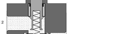
3 Directional Control Valve Construction type Poppet valves Slide valves Poppet valves With poppet valves the connections are opened and closed by means of balls, discs, plates or cones. The valve seats are usually sealed simply using flexible seals. Characteristics: Seat valves have few parts which are subject to wear and hence they have a long service life. Absolutely tight. They can switch quickly over short strokes. Insensitive to dirt and are robust. Need high actuating force (relatively high as it is necessary to overcome the force of the built-in reset spring and the air pressure). Can be actuated from one side only. 3


4 Slide Valves In slide valves, the individual connections are linked together or closed by means of spools or plate slide valves. Characteristics: Easy to produce. Compact size. Low actuating force required. Can be actuated t dfrom both sides. Long switching strokes. Limited tightness. Sensitive to dirt. 4


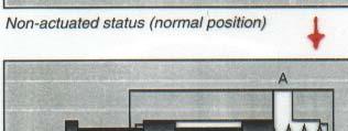
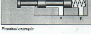
5 Overlapping The term overlapping describe the behavior of the valve during the switch over phase. With overlapping if during the switching phase ports A, P, and R are connected. Without overlapping, the connection of P to A after closing R. 5
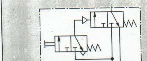
6 6

7 7


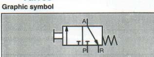
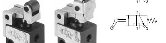
8 3/2 Directional Control Valve, Manual operated by push button, normally closed, return by spring, slide valve. 8


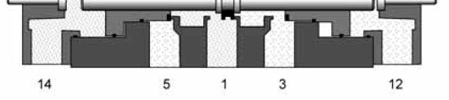
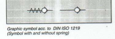
 Graphical")
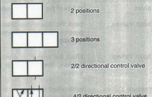
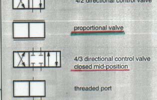
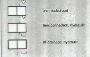
9 Graphical Symbols For Directional Control Valves Number of switching positions = Number of squares. Number of ports = Number of port marks (main ports only. No control ports are counted) Graphical symbols with additional lines = continuously adjustable valve. 9
10 Home positions Normal Position: The normal position on valves with existing reset, e.g. spring, refers to the switching position assumed by the moving parts of the valve, if the valve is not connected. Initial Position: The initial position is the switching position assumed by the moving parts of a valve after the valve has been installed in a system and the system pressure has been switched on and possibly also the electrical voltage, and with which the designated switching program starts. Valve Description 1. Number of ports. 2. Number of switching position. 3. Valve type. 4. Type of actuation. 5. Type of return. 6. Type of mid position sealing. 7. Construction type (If you can) 10
11 11

12 12
13 Working lines Pilot lines 13

14 Manual Operated 14

15 Mechanical Operated 15
16 Piloted Operated Electrical Operated 16


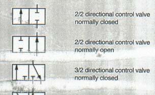
17 2/2 Directional Control Valve (On-Off Valve) 17
18 2/2 Directional Control Valve (On-Off Valve) The 2/2-way valve has two ports and two positions (open, closed). It is rarely used except as an on-off valve, since its only function is to enable signal flow through and cannot release the air to atmosphere once in the closed position in contrast to the 3/2-way valve. The 2/2-way valve is normally of the ball seat construction. This valve can be operated either manually, mechanically or pneumatically 3/2 Directional Control Valve 18

19 3/2 Directional control Valve 19
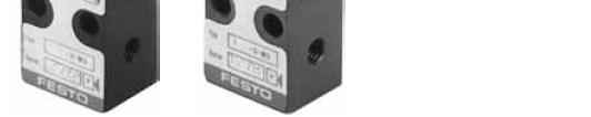
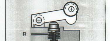
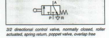
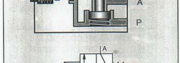
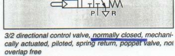
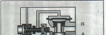
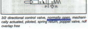
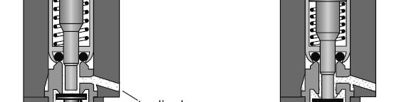
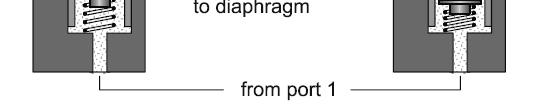
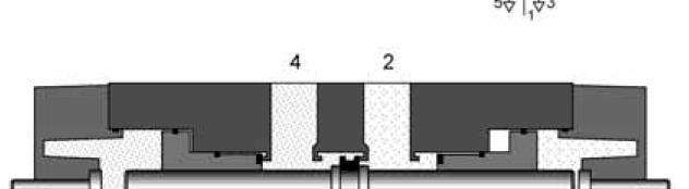
20 3/2 Directional Control Valve The valve shown here is constructed on the disc seat principle. The sealing is simple but effective. The response time is short and a small movement results in a large crosssectional area being available for air flow. Like the ball seat valves, they are insensitive to dirt and thus have a long service life. The 3/2-way valves are used for controls employing single-acting cylinders or for generating signals supplied to control elements. 3/2 Directional control Valve 20
21 3/2 Directional control Valve 3/2 Directional control Valve 21

22 3/2 Directional control Valve 22
23 3/2 Directional Control Valve 3/2 Directional Control Valve The construction of the valve is simple. Actuation is effected by displacing the grip sleeve lengthwise. This valve is used as a shut-off valve, primarily for the pressurising and exhausting of control systems or system components. 23
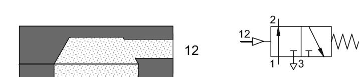
24 3/2 Directional Control Valve In the actuated state, connection 1 and 2 are connected and the valve is switched to flow. The valve is actuated t either manually or mechanically. The actuation force required is dependent on the supply pressure, spring force and the friction in the valve. The actuation force limits the feasible size of the valve. The construction of the ball seat valve is very simple and compact. 24
25 4/2 Directional Control Valve 4/2 Directional Control Valve 25


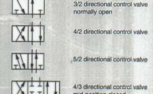
26 4/2 Directional Control Valve Actuation of the valve: When the two plungers are actuated simultaneously, 1 to 2 and 4 to 3 are closed by the first movement. By pressing the valve plungers further against the discs, opposing the reset spring force, the passages between 1 to 4 and from 2 to 3 are opened. The valve has a nonoverlapping exhaust connection and is returned to its start position by the spring. The valves are used for controls employing double-acting cylinders. There are other actuating methods and types of construction available for the 4/2-way valve including push button, single air pilot, double air pilot, roller lever actuated, spool and sliding plate. In the main, the 4/2- way valve is utilised in similar roles as the 5/2-way valve. 26
27 4/3 Directional Control Valve 27
28 4/3 Directional Control Valve 28
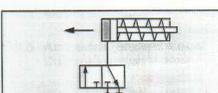
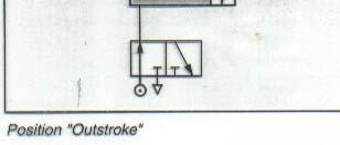
29 4/3 Directional Control Valve In this circuit diagram the lines of the 4/3-way valve are closed in the middle position. This enables the piston rod of a cylinder to be stopped in any position over its stroke range, although intermediate positions of the piston rod cannot be located with accuracy. Owing to the compressibility of air, another position will be assumed if the load on the piston rod changes. Indirect Control (Piloted Operated) Piloted valves are not actuated directly but they are controlled by a pressure signal. The main valve is actuated by the pressure of the medium to be controlled. The purposes of piloted valves are: Reduce the actuating force (also with large diameter). Minimum pressure necessary. Allow the use of smaller solenoid size. (Note: the piloted valve has a longer switching time than with directly actuated valves). 29
30 30
31 31
32 32

33 33

34 34

35 35
36 36
37 - Memory Function. - Impulse Operated. 37
38 38
39 5/3 Directional Control Valve In general the 4/2-way valve is replaced by the 5/2-way valve. The 5/2- way valve has advantages in passage construction and allows the exhaust of both extension and retraction air for cylinders to be separately controlled. The 5/2-way valve circuit carries out the same primary control functions as the 4/2-way valve circuit 5/3 Directional Control Valve 39

 is energized, it")

40 Solenoid Valves A very common way to actuate a spool valve is by using a solenoid, illustrated t in the following figure. As shown, when the electric coil (solenoid) is energized, it creates a magnetic force that pulls the armature in to the coil. This cause the armature to push the spool of the valve. Solenoid switching behavior depends on excitation type. 40
41 41
42 Solenoid Valve Electrical Characteristics Operating time for attraction and release. Supply: DC or AC. Power consumption: hold on power and inrush power. Protection methods: against accidental contact, water proof, pressure proof. Duty cycle (%). DC Solenoid Characteristics Slower switching on and off (Self Inductance). Cut-out spikes. Smooth attraction. Safe against overload even with blocked armature. Bulkier than AC solenoid. Longer life. Resistance is equal to the ohmic resistance of the coil. Need freewheeling protection circuit. 42
43 AC Solenoid Characteristics Switching Fast and hard (due to reduced resistance at the moment of switching on, the reactance net yet having developed). High current drain when the armature is blocked. Smaller than DC solenoid. Eddy current and hysteresis losses. Total resistance consists of the ohmic resistance and reactance. Cannot be operate by direct current. Shorter life time. Noisy. Dc solenoid Ac solenoid 43
44 Air Return The return of valve can be operated by a spring as well as by pneumatic pressure. When the return by pressure is integrated into the valve as a pneumatic feature it is known as air return. 44
45 Manual Override Pneumatically or electrically operated valves are often equipped with iha manual override. Thus operation is also possible in cases where the control energy is not available. 45
46 46
47 Valves With Differential Piston Actuation For valves pressurized from both sides, the control can be by pistons of equal or different sizes. Non-Return Valves (Isolating Valves) Non-return valves are devices which preferentially stop the flow in one direction and permit flow in the opposite direction. Non-Return valves Include: One Way Valves (Check Valves). Shuttle Valve (Logic OR Valve). Dual Pressure Valve (Logic AND Valve). Quick Exhaust Valves. Shutoff Valves 47


48 One Way Valve (Check Valve) 48


49 Unlatchable Check Valve This valve offers the possibility of canceling the check action in the blocking direction by means of a control signal applied to the additional pilot port. In this way, flow through the valve is possible in either one direction or the other. Unlatchable Check Valve 49
50 Dual Pressure Valve (AND Valve) (Double Cutoff Valve) 50
51 Shuttle Valve (OR Valve) 51
52 52
53 Logic Not Valve 53


54 Quick Exhaust Valve Quick Exhaust Valve 54
55 Shutoff Valve 55


.")
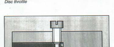
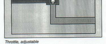
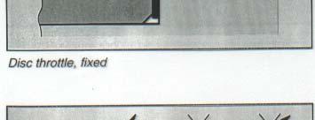
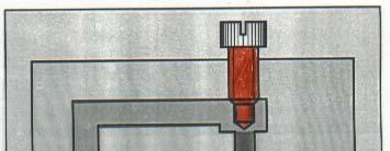
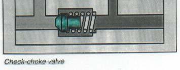
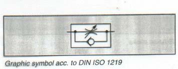
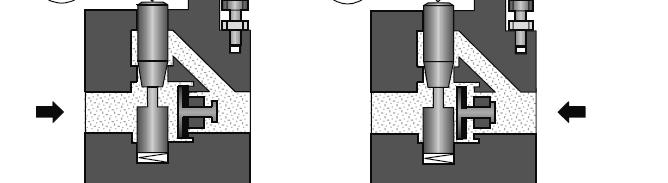
56 Flow Control Valves Q = A P Flow control valves influence the volumetric flow of the compressed air in both directions. Flow Control valves Include: Throttle Valves. - Chock Throttle Valves. - Disc Throttle Valves. One Way flow control valves (Check Chock Valves). - Manually Adjustable. - Mechanically Adjustable. 56

57 Bi-Directional Chock Valves 57


58 One Way, Manually Adjustable Flow Control Valve (Check Chock Valve) 58
59 One Way Mechanically Adjustable Flow Control Valve 59
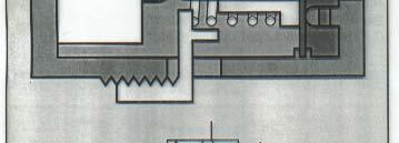
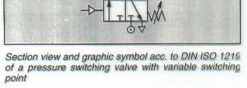
60 Pressure Control Valves Pressure control valves are elements which predominantly influence the pressure or are controlled by the magnitude of the pressure. They are divided into the three groups: Pressure regulating valve (Pressure Reduce Valve) Pressure limiting iti valve (Pressure Relief Valve) Pressure sequence valve (Pressure Switch). Pressure Regulator 60

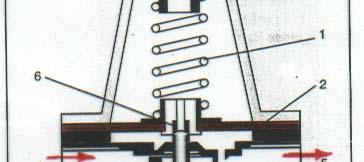
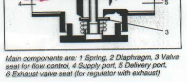
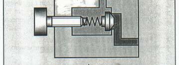
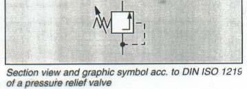
61 Pressure Relief Valve 61
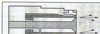
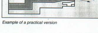
62 Pressure Relief Valve The pressure limiting valves are used mainly as safety valves (pressure relief valves). They prevent tthe maximum permissible ibl pressure in a system from being exceeded. If the maximum pressure has been reached at the valve inlet, the valve outlet is opened and the excess air pressure exhausts to atmosphere. The valve remains open until it is closed by the built-in spring after reaching the preset system pressure. Pressure Sequence Valve 62

63 Pressure Sequence Valve 63
64 Combinational valves Components of different control groups can be combined into the body of one unit with the features, characteristics and construction of a combination of valves. Time delay valves: for the delay of signals. 5/4-way valve: for the stopping of double- acting cylinders in any position. i Vacuum generator with ejector: for pick and place applications 64

65 Time Delay valves The time delay valve is a combined 3/2-way valve, one way flow control valve and air reservoir. The 3/2-way valve can be a valve with normal position open or closed. The delay time is generally 0-30 seconds for both types of valves. By using additional reservoirs, the time can be extended. An accurate switch-over time is assured, if the air is clean and the pressure relatively constant. Time Delay Valve (Normally Closed) 65


66 Time Delay Valve (Normally Open) Time Delay Valve 66
67 Time Delay ON Time Delay OFF 67
68 68
69 Pneumatic Proximity Sensors With pneumatic proximity sensors the presence and absence of an object is detected by means of contactless sensing with air jet (Flapper and Nozzle system). When an object is present, a signal pressure change occurs, which h can be further processed. Pneumatic Proximity Sensors Advantages Operational safety in dusty environments. Operational safety with high ambient temperature. Can be used in areas of explosion hazard. Insensitive to magnetic influences and sound waves. Reliable even in extreme ambient brightness and for sensing of light transparent objects where optical proximity sensors may not be suitable. 69
70 Pneumatic Proximity Sensors Disadvantage Since the price of a complete proximity sensors (Nozzle, pressure amplifier and pressure switch) is generally higher than that of a standard inductive, capacitive or even optical proximity sensors, pneumatic proximity sensors are used preferably for special applications where other proximity sensors are unsuitable. Pneumatic Proximity Sensors Types Back pressure sensor (Pilot Tube). Reflex Sensor (Reflection eye). Air barrier sensor (Air Gate). 70
71 Pneumatic Proximity Sensors For all sensors types the signal pressure generated depends on the supply pressure and the distance between the nozzle and the object. Detectable distance range from 0 to 100 mm. Pneumatic Proximity Sensors Requirements Reduce the system air pressure to a low pressure range by using pressure regulator. Clean and oil free air is essential. As the pneumatic signal is generated too weak for further evaluation, a pressure amplifier needs to be connected downstream. A pneumatic proximity sensor with binary electric output signal is created with the help of pneumatic to electrical converters (Electrical pressure switch). 71


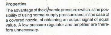
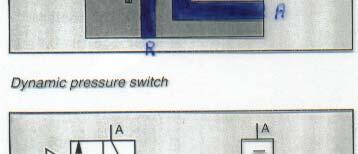
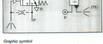
72 Back Pressure Sensor (Pilot tube) The obstructing of an air jet (Nozzle) by means of an object to be detected leads to a signal pressure build-up in the control port to the level of the supply pressure. When the nozzle is completely covered (full effeteness obtained), an output pressure will be at the same level with supply pressure. By chocking the air supply and by appropriate channel shaping you can use a normal pressure level as supply pressure to the sensor. In this case, an amplification of the output is unnecessary, and at the same time, the air consumption is reduced. For this type, the sensing distance is between 0 to 0.5 mm. 72
 and central receiver nozzle arranged concentrically.")


73 Reflex Sensor (Screen Nozzle) The reflex type sensor consists of an annular ring jet nozzle (Emitter) and central receiver nozzle arranged concentrically. Function: The annular air flow causes a negative pressure in the centrally positioned receiver channel if the air flow is not unobstructed. When the object approaches, the pressure becomes positive and reaches the supply value when the nozzle is completely obstructed. The following curve represents the relationship between the output signal and the sensing distance. 73
 up to 15 mm.")
 bar, the usable output signal pressure range is")
74 Reflex Sensor (Screen Nozzle) For this type, the sensing distance is between (2 to 6 mm) up to 15 mm. For a supply pressure of (0.1 to 0.5) bar, the usable output signal pressure range is (0.5 to 2) mbar. 74
75 75
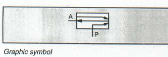
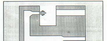
76 Reflex Sensor Circuit Diagram Air Barrier Sensor By placing a ring jet nozzle (Emitter) directly opposite a receiver nozzle, it is possible to construct an air barrier which is interrupted by an object. There are two types of air barrier sensor: Air barrier without pressure receiver. Air barrier with Pressure receiver. For this type, the sensing distance is up to 100 mm. 76
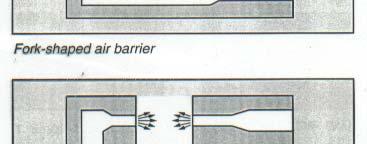
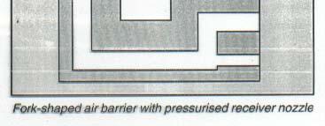
77 Air barrier Sensor With out Pressure receiver: Simple construction, Consists of: Transmitter nozzle, normal receiver nozzle (with out pressure). The disadvantage of this type the sensitivity to external influence (dust) With Pressure receiver: In order to reduce the sensitivity to external influences, the receiver nozzle is pressurized. Air barrier with out Pressure receiver 77


78 Air barrier with Pressure receiver 78
79 79
80 Air Barrier Sensor Air barrier are pressurized with low pressure (0.1 to 0.5) bar, in order to obtain a usable output signal pressure from (0.5 to 2) mbar. This signal must be amplified. 80

81 81
82 82

83 83


84 84
85 85

86 86
87 87
PNEUMATIC & HYDRAULIC SYSTEMS
 PNEUMATIC & HYDRAULIC SYSTEMS CHAPTER SIX PNEUMATIC SYSTEM DESIGN AND DEVELOPMENT Dr. Ibrahim Naimi Symbols And Standards In Pneumatics The development of pneumatic systems is assisted by a uniform approach
: Automation Laboratory 1
 Table A.1 shows elements found in FluidSIM library with a brief description for each of them. Compressed air supply The compressed air supply provides the needed compressed air. It contains a pressure
Pneumatic Control System
 Matakuliah: Teknik Otomasi Pneumatic Control System Eka Maulana, ST, MT, MEng. What is Pneumatic? Pneumatics is a type of power transmission that uses a gas ( in our case, air) and pressure differential
[You may download this article at: https://fluidsys.org/downloads/ ]
![[You may download this article at: https://fluidsys.org/downloads/ ]](/thumbs/75/72588514.jpg "[You may download this article at: https://fluidsys.org/downloads/ ]") Fluidsys Training Centre, Bangalore offers an extensive range of skill-based and industry-relevant courses in the field of Pneumatics and Hydraulics. For more details, please visit the website: https://fluidsys.org
Fluidsys Training Centre, Bangalore offers an extensive range of skill-based and industry-relevant courses in the field of Pneumatics and Hydraulics. For more details, please visit the website: https://fluidsys.org
Electro - Hydraulics. & Pneumatics. Electro Hydraulic Press. Comparison. Electro Hydraulics. By: Alireza Safikhani
 Electro - 9 Hydraulics & Pneumatics 2 Electro Hydraulic Press The hydraulic press is controlled via the electrical control panel. Electrical signals are used to activate the valves in the hydraulic installation.
CH.4 Basic Components of Hydraulic and Pneumatic System/16 M HAP/17522/AE5G
 Content : 4.1 Hydraulic and Pneumatic actuators. 10 Marks Hydraulic Actuators - Hydraulic cylinders (single, double acting and telescopic) construction and working, Hydraulic motors (gear and piston type)
Design and Fabrication of Sequencing Circuit with Single Double Acting Cylinder
 Design and Fabrication of Sequencing Circuit with Single Double Acting Cylinder V.G.Vijaya Department of Mechatronics Engineering, Bharath University, Chennai 600073, India ABSTRACT: This project deals
Subject: Pneumatic Training Kit with portable Air Compressor
 MSME TOOL ROOM: HYDERABAD (CENTRAL INSTITUTE OF TOOL DESIGN) Balanagar, Hyderabad 500 037 TEL.NO.23772747, 23776168 FAX No.0-4023772658 E-mail:citdpurchase@citdindia.org Visit us: www.citdindia.org. TENDER
Module 2 CONTROL SYSTEM COMPONENTS. Lecture - 4 RELAYS
 1 Module 2 CONTROL SYSTEM COMPONENTS Lecture - 4 RELAYS Shameer A Koya Introduction Relays are generally used to accept information from some form of sensing device and convert it into proper power level,
Test. What type of cylinder would you use? A. Single-acting cylinder B. Double-acting cylinder Answer:
 Test This test allows you to establish whether your basic knowledge of pneumatic controls is sufficient for you to attend the advanced course P or whether you should attend the basic level course P. The
Hydraulic energy control, conductive part
 Chapter 2 2 Hydraulic energy control, conductive part Chapter 2 Hydraulic energy control, conductive part To get the hydraulic energy generated by the hydraulic pump to the actuator, cylinder or hydraulic
Appendix A. Standard Symbols for Hydraulic Components
 Table B.1 Flow lines Appendix A Standard Symbols for Components Continuous flow E Pilot connection L L>10E E Drain connection L L
Pneumatic & Hydraulic SYSTEMS
 Pneumatic & Hydraulic SYSTEMS CHAPTER EIGHT HYDRAULIC PUMPS AND ACTUATORS Dr. Ibrahim Naimi The higher the discharge pressure, the lower the volumetric efficiency because internal leakage
Module 5: Valves. CDX Diesel Hydraulics. Terms and Definitions. Categories of Valves. Types of Pressure Control Valves
 Terms and Definitions Categories of Valves Types of Pressure Control Valves Types and Operation of Pressure Relief Valves Operation of an Unloading Valve Operation of a Sequencing Valve Operation of a
Lesson 5: Directional Control Valves
 : Directional Control Valves Basic Hydraulic Systems Hydraulic Fluids Hydraulic Tank Hydraulic Pumps and Motors Pressure Control Valves Directional Control Valves Flow Control Valves Cylinders : Directional
For system diagrams and component identification
 Pneumatic Symbols For system diagrams and component identification Contents Standards Actuators Basic symbols Valve symbol structure t Functional elements Flowlines Connections Conditioners and plant Pressure
Technical Principles of Valves
 Technical Principles of Valves Symbols and Circuit Functions Symbol to DIN-ISO 1219 The circuit function illustrations are defined to the DIN-ISO 1219 Standard. These can be used to show other switching
ADVANCED CUSTOMIZED ELECTRO PNEUMATIC TRAINER (PRODUCT CODE: SAP 20B)
") The Advanced Customized Electro Pneumatic Trainer (SAP 20B) is capable of being used to demonstrate the design, construction and application of electro-pneumatic components and circuits. Objectives:- The
The Advanced Customized Electro Pneumatic Trainer (SAP 20B) is capable of being used to demonstrate the design, construction and application of electro-pneumatic components and circuits. Objectives:- The
Industrial Pneumatic Systems Syllabus [Detailed]
![Industrial Pneumatic Systems Syllabus [Detailed]](/thumbs/81/83340511.jpg "Industrial Pneumatic Systems Syllabus [Detailed]") TECHNICAL TRAINING - SWAPPING DOWNTIME FOR PRODUCTIVITY! Industrial Pneumatic Systems Syllabus [Detailed] 1. Fundamentals of Fluid Power Systems. The three states of matter. Definition of a fluid. Derivation
TECHNICAL TRAINING - SWAPPING DOWNTIME FOR PRODUCTIVITY! Industrial Pneumatic Systems Syllabus [Detailed] 1. Fundamentals of Fluid Power Systems. The three states of matter. Definition of a fluid. Derivation
Chapter B-6. Chapter 6. Systems. Festo Didactic TP101
 223 Chapter 6 Systems Festo Didactic TP101 224 6.1 Selection and comparison of working and control media To select the working and control media consideration must be given to the following:! The work
LogSplitterPlans.Com
 Hydraulic Pump Basics LogSplitterPlans.Com Hydraulic Pump Purpose : Provide the Flow needed to transmit power from a prime mover to a hydraulic actuator. Hydraulic Pump Basics Types of Hydraulic Pumps
Module 6 Assignment Part A
 Module 6 Assignment Part A TOTAL MARKS Part A = 192 TOTAL QUESTIONS Part A = 36 Question 1 [3 Marks] What does pressure refer to in relation to hydrostatics and what is it dependent on? Question 2 [14
2. Hydraulic Valves, Actuators and Accessories. 24 Marks
 2. Hydraulic Valves, Actuators and Accessories 24 Marks Co related to chapter 602.2 Describe working principle of various components used in hydraulic & pneumatic systems. 602.3 Choose valves, actuators
three different ways, so it is important to be aware of how flow is to be specified
 Flow-control valves Flow-control valves include simple s to sophisticated closed-loop electrohydraulic valves that automatically adjust to variations in pressure and temperature. The purpose of flow control
INDIAN INSTITUTE OF TECHNOLOGY KHARAGPUR NPTEL ONLINE CERTIFICATION COURSE. On Industrial Automation and Control
 INDIAN INSTITUTE OF TECHNOLOGY KHARAGPUR NPTEL ONLINE CERTIFICATION COURSE On Industrial Automation and Control By Prof. S. Mukhopadhyay Department of Electrical Engineering IIT Kharagpur Topic Lecture
SAP E & C ADVANCED CUSTOMIZED ELECTRO PNEUMATIC TRAINER (FOR ITI) (PRODUCT CODE: SAP 20B-I)
 (PRODUCT CODE: SAP 20B-I)") The Advanced Customized Electro Pneumatic Trainer (SAP 20B-I) is capable of being used to demonstrate the design, construction and application of electro-pneumatic components and circuits. Objectives:-
The Advanced Customized Electro Pneumatic Trainer (SAP 20B-I) is capable of being used to demonstrate the design, construction and application of electro-pneumatic components and circuits. Objectives:-
Ch 4 Motor Control Devices
 Ch 4 Motor Control Devices Part 1 Manually Operated Switches 1. List three examples of primary motor control devices. (P 66) Answer: Motor contactor, starter, and controller or anything that control the
Push buttons are of two types i) Momentary push button ii) Maintained contact or detent push button
 Momentary push button ii) Maintained contact or detent push button") ELECTRO-PNEUMATIC Push button switches A push button is a switch used to close or open an electric control circuit. They are primarily used for starting and stopping of operation of machinery. This causes
ELECTRO-PNEUMATIC Push button switches A push button is a switch used to close or open an electric control circuit. They are primarily used for starting and stopping of operation of machinery. This causes
Section 6.1. Implement Circuit - General System. General: TF Configuration TB Configurations Implement Control Valve:
 Section 6.1 Implement Circuit - General System General: TF Configuration... 6.1.3 TB Configurations... 6.1.5 Implement Pump Breakdown... 6.1.6 Operational Description: General... 6.1.7 Compensator Control...
LECTURE 15 TO 17 DIRECTIONAL CONTROL VALVES FREQUENTLY ASKED QUESTIONS
 LECURE 15 O 17 DIRECIONL CONROL VLVES FREQUENLY SKED QUESIONS 1. Explain briefly the function of directional control valves o o start, stop, accelerate, decelerate and change the direction of motion of
What does pressure refer to in relation to hydrostatics and what is it dependent on?
 Question 1 [3 Marks] What does pressure refer to in relation to hydrostatics and what is it dependent on? Question 2 [14 Marks] Make a circuit diagram of a regular hydraulic plant that is used to control
MOTOR TERMINAL CONNECTIONS
 MOTOR TERMINAL CONNECTIONS Motor Classification Most of the industrial machines in use today are driven by electric motors Motors are classified according to the type of power used (AC or DC) and the motors
MAGNETIC MOTOR STARTERS
 Chapter 6 MAGNETIC MOTOR STARTERS 1 The basic use for the magnetic contactor is for switching power in resistance heating elements, lighting, magnetic brakes, or heavy industrial solenoids. Contactors
JIS symbols used in this catalog are old symbols following JISB0125-1: Refer to JISB0125-1: 2007 or JFPS2011: 2006 for new symbols.
 symbol s used in this catalog are old symbols following JISB0-: 00. Refer to JISB0-: 007 or JFPS0: 006 for new symbols. Page. Element of symbol. Line and port. Directional control valve. Pressure control
3/3 servo directional control valve with mechanical position feedback
 Courtesy of CMA/Flodyne/Hydradyne Motion Control Hydraulic neumatic Electrical Mechanical () 426-4 www.cmafh.com 3/3 servo directional control valve with mechanical position feedback Type 4WS2EM...XN...-114
Test Which component has the highest Energy Density? A. Accumulator. B. Battery. C. Capacitor. D. Spring.
 Test 1 1. Which statement is True? A. Pneumatic systems are more suitable than hydraulic systems to drive powerful machines. B. Mechanical systems transfer energy for longer distances than hydraulic systems.
TECHNICAL GUIDE FOR PROXIMITY SENSORS DEFINITIONS YAMATAKE PROXIMITY SENSOR CATEGORIES
 TECHNICAL GUIDE FOR PROXIMITY SENSORS DEFINITIONS "" includes all sensors that detect the presence of a metallic object approaching the sensing face or near the sensing face without mechanical contact.
Directional servo-valve of 4-way design
 Courtesy of CM/Flodyne/Hydradyne Motion Control Hydraulic Pneumatic Electrical Mechanical (0) 426-54 www.cmafh.com Directional servo-valve of 4-way design Type 4WSE3E 32 Size 32 Component series 5X Maximum
Solenoid valve. Solenoid Coil
 Solenoid valve Solenoid valve Solenoid Coil Plunger Valve body A simple solenoid valve consists ofi: Valve body with a plunger the plunger is made of metal Coil an electrical coil if the coil is given
Electropneumatics Basic Level Set of Overhead Transparencies TP 201
 Electropneumatics Basic Level Set of Overhead Transparencies TP 0 Festo Didactic 0950 en Order No.: 0950 Description: EL-PN.FOLIEN-GS Designation: D:OT-TP0-GB Edition: 0/000 Author: Frank Ebel Graphics:
PREHEATER BYPASS SYSTEMS
 PREHEATER BYPASS SYSTEMS PREHEATER BYPASS SYSTEMS OVERVIEW 2014 GS FEED WATER HEATER BYPASS SYSTEM General Description These valves are designed to bypass high pressure feed water around the pre-heaters
INTRODUCTION TO SENSORS, TRANSDUCERS & ACTUATORS
 INTRODUCTION Transducers play a major role in mechatronics engineering & technology. These are the basic elements that convert or transform one form of energy to another form. Let us change the word energy
Suggested list for the Hydraulic and Pneumatic lab Instruments Mechatronics Engineering Department School of Applied Technical Science
 Suggested list for the Hydraulic and Pneumatic lab Instruments Mechatronics Engineering Department School of Applied Technical Science Pneumatic and Electro-pneumatic components: No. EQUIPMENTS operating
VB VALVES & AUTOMATION
 Introduction to Valve What are Valves? Valves are mechanical device that controls the flow and pressure within a system or process. They are essential components of a piping system that conveys liquids,
Mini 1. Compact High Flow 3-Way and 4-Way Pneumatic Directional Control Valves
 Catalog LX-530 Mini 1 Compact High Flow and Pneumatic Directional Control Valves FEATURES: 3-port or 5-port bodies Manual, Air Pilot, Solenoid or Mechanical Operators Two-position, Single or Dual Actuation
Pneumatic Power Valves Series 75/76 Manual, Mechanical, Pneumatic and Electric Valves
 Quic-Pics Catalogue Pneumatic Power Valves Series 75/76 Manual, Mechanical, Pneumatic and Electric Valves Contents: Product Line Overviews 2 Manually Operated Valves 5 Pushbuttons 6 Toggle Switch 8 Knob
Chapter 6 Pneumatic Logic Sensors and Actuators
 Chapter 6: Penumatic logic sensors and actuators -IE337 Chapter 6 Pneumatic Logic Sensors and Actuators 1 Introduction to Pneumatic Why pneumatic? Pneumatic control system is frequently used in building
DG 060 DG 061 DG 062 DG 063 DG 064 for Pressure and High Pressure Filters Operating pressure up to 600 bar Response/switching pressure up to 5,0 bar
 Clogging Indicators DG 060 DG 061 DG 062 DG 063 DG 064 for Pressure and High Pressure Filters Operating pressure up to 600 bar Response/switching pressure up to 5,0 bar Description Application Monitoring
The pneumatic circuit and parts' list needed to perform this operation are shown by Figure C.1.
 Introduction In session 1 you have learned about pneumatic systems and their main components. In addition to that your lab instructor has introduced to you how to use FluidSIM software. During this appendix
SINGLE-ACTING ACTUATORS FOR DOUBLE-ACTING & SERIES 65 POSITIONERS PNEUMATIC & ELECTRO-PNEUMATIC. The High Performance Company
 POSITIONERS PNEUMATIC & SERIES 65 FOR DOUBLE-ACTING & SINGLE-ACTING ACTUATORS The High Performance Company SERIES 65 FEATURES The Brayline Series 65Pneumatic and Electro-Pneumatic Positioner feature modular
Compact Proportional Solenoid Valve
 Compact Proportional Solenoid Valve Series Repeatability: % or less Hysteresis:1% or less Fluid Flow rate control range Note) Series Air, Inert gas to L/min to L/min Note) Varies depending on the model.
Introduction. General Information. Systems Operation
 Systems Operation Introduction Reference: For illustrated Specifications, refer to the Specifications For 416, 426, 428, 436, 438, & Series II Backhoe Loaders Transmission, Form No. SENR3131. If the specifications
Daniel. Liquid Control Valves Technical Guide. Technical Guide DAN-LIQ-TG-44-rev0813. DAN-LIQ-TG-44-rev0208. February 2008.
 DAN-LIQ-TG-44-rev0208 February 2008 Daniel Liquid Control Valves Technical Guide www.daniel.com Daniel Measurement and Control Theory, Principle of Operation and Applications This brochure has been prepared
R-MAG Vacuum Circuit Breaker with Magnetic Actuator Mechanism 15.5 kv - 27 kv; 1200 A A
 R-MAG Vacuum Circuit Breaker with Magnetic Actuator Mechanism 15.5 kv - 27 kv; 1200 A - 3700 A R-MAG The R-MAG is truly the next generation in vacuum circuit breakers, combining industry recognized magnetic
ORIGA Pneumatic Linear Drives OSP-L
 ORIGA Pneumatic Linear Drives OSP-L Very long lifetime and lowest leakage A NEW Modular Linear Drive System With this second generation linear drive Parker Origa offers design engineers complete flexibility.
Pilot-Operated Directional Control Valves Series D3 - D11
 Catalogue HY11-500/UK Characteristics The D31, D41, D81, D91 and D111 are electrical controlled 4/3 or 4/ way directional control valves. The valves are pilot-operated by an NG6 valve. Pressure and flow
What is hydraulic power pack?
 What is hydraulic power pack? What are the hydraulic power pack applications? Mobile hydraulics applications increasing so much with hydraulic power pack recently. Such as, dump trailers, electric sanitation
Load Cell for Manually Operated Presses Model 8451
 w Technical Product Information Load Cell for Manually Operated Presses 1. Introduction... 2 2. Preparing for use... 2 2.1 Unpacking... 2 2.2 Using the instrument for the first time... 2 2.3 Grounding
DESYsmart / TESYsmart steam test unit
 0 DESYsmart / TESYsmart steam test unit Electronic pressure monitoring system for controlling fittings with safetyrelevant tasks in accordance with TRD 4, DIN EN ISO46, AD data sheet A and safety concept
Winding technology, pneumatically actuated tension brakes
 Winding technology, pneumatically actuated tension brakes Pneumatically actuated tension brakes with internally ventilated brake disc Series 0454 Operation 7.03.00 Properties, areas of application 7.03.00
Relay. for Experiments with the fischertechnik Expansion Kit. Order No
 Relay for Experiments with the fischertechnik Expansion Kit Order No. 30075 About the Relay A relay is an electromagnetic switch. It consists essentially of two assemblies. 5 6 7 3 2 1. Technical Data
Clogging Indicators. Description. Page 393. Application Monitoring the contamination of pressure and high pressure filters.
 Clogging Indicators DG 023 DG 024 DG 041 DG 042 for Pressure and High Pressure Filters Operating pressure up to 450 bar / 5627 psi Response / switching pressure up to 5.0 bar / 73 psi Description pplication
Pilot Operated Directional Control Valves Series D31DW, D41VW - D111VW
 Characteristics The D31, D41, D81, D91 and D111 are electrically controlled 4/3 or 4/ way directional control valves. The valves are pilot operated by an NG6 valve. Pressure and flow of the pilot oil have
Fluidics. Hydraulic circuit. Course teacher Prof. Mahbubur Razzaque
 COURSE NUMBER: ME 433 Fluidics Hydraulic circuit Course teacher Prof. Mahbubur Razzaque 1 FAIL-SAFE CIRCUITS Fail-safe circuits are those designed to prevent injury to the operator or damage to equipment.
DISCUSSION OF FUNDAMENTALS. A hydraulic system can be controlled either manually or automatically:
 Unit 1 Introduction to Electrical Control of Hydraulic Systems UNIT OBJECTIVE When you have completed this unit, you will be able to identify the components used for electrical control of the Hydraulics
FRL unit consist of Filterations, Regulators and Lubricator unit.
 4.1 AIR CONTROL 4.1.1 Fluid Conditioner FRL unit consist of Filterations, Regulators and Lubricator unit. It is also known as Air Service Unit. Primary function is to provide clean air at optimal pressure
Contents. Pressure measurement technology Pressure calibrators 18 Exercises 19-20
 1 Pressure Contents Topics: Slide No: Pressure measurement technology 03-17 Pressure calibrators 18 Exercises 19-20 2 Pressure Gauges Barometer Used to measure Barometric Pressure Reference is 0 psia,
DG 023 DG 024 DG 025 DG 041 DG 042. Clogging Indicators
 Clogging Indicators DG 03 DG 04 DG 05 DG 041 DG 04 For Pressure and High Pressure Filters Operating pressure up to 657 psi Response/Switching pressure up to 73 psi 60.30-4us Description Application Monitoring
Machine bolt shut-off nozzle type BHP pneumatically or hydraulically controlled
 Machine bolt shut-off nozzle type BHP pneumatically or hydraulically controlled Applications: Thermoplastics (not applicable for PVC) Shut-off mechanism: Bolt shut-off with integrated 2-way actuator pneumatically
MECHATRONICS LAB MANUAL
 MECHATRONICS LAB MANUAL T.E.(Mechanical) Sem-VI Department of Mechanical Engineering SIESGST, Nerul, Navi Mumbai LIST OF EXPERIMENTS Expt. No. Title Page No. 1. Study of basic principles of sensing and
The filling pressure of SUSPA gas springs depends on the extension force and the geometry and is between 10 and 230 bar.
 FAQ s 1. Why is there a warning on the gas spring? Gas springs are filled with compressed nitrogen. The warning is intended to prevent unauthorized people from opening the gas spring or making other changes
SDigital vs. Analog Sensors
 How Sensors Are Used in Fluid Power Systems Sensors are used as input devices in fluid power systems to indicate that a condition has been, or has not been, met. Sensors can be used to monitor pressure,
A system of lubricant dispensing devices (oil or grease) connected by piping to a central pumping unit that is operated automatically or manually.
 connected by piping to a central pumping unit that is operated automatically or manually.") Air/Oil Systems: A lubrication system in which small measured quantities of oil are introduced into an air/oil mixing device which is connected to a lube line that terminates at a bearing, or other lubrication
Air/Oil Systems: A lubrication system in which small measured quantities of oil are introduced into an air/oil mixing device which is connected to a lube line that terminates at a bearing, or other lubrication
Exercise 4-1. Flowmeters EXERCISE OBJECTIVE DISCUSSION OUTLINE DISCUSSION. Rotameters. How do rotameter tubes work?
 Exercise 4-1 Flowmeters EXERCISE OBJECTIVE Learn the basics of differential pressure flowmeters via the use of a Venturi tube and learn how to safely connect (and disconnect) a differential pressure flowmeter
Festo Modular Production System (MPS)
") ELEC E8114 Manufacturing Automation Systems Modelling Festo Modular Production System (MPS) Figure 1 Distribution station (left) and testing station (right) 1 Introduction The purpose of this document
ELEC E8114 Manufacturing Automation Systems Modelling Festo Modular Production System (MPS) Figure 1 Distribution station (left) and testing station (right) 1 Introduction The purpose of this document
LESSON 2 BASIC CONSTRUCTION AND OPERATION OF HYDRAULIC ACTUATING DEVICES, FLOW CONTROL, AND DIRECTIONAL DEVICES. STP Tasks:
 LESSON 2 BASIC CONSTRUCTION AND OPERATION OF HYDRAULIC ACTUATING DEVICES, FLOW CONTROL, AND DIRECTIONAL DEVICES STP Tasks: 552-758-1003 552-758-1071 OVERVIEW LESSON DESCRIPTION: In this lesson you will
Kuhnke Technical Data. Contact Details
 Kuhnke Technical Data The following page(s) are extracted from multi-page Kuhnke product catalogues or CDROMs and any page number shown is relevant to the original document. The PDF sheets here may have
ME 360 Test #3 Spring 08 5/5/08. Closed book, closed notes portion of test. Total of 25 out of 100 points for questions #1 to #6.
 ME 360 Test #3 Spring 08 5/5/08 Closed book, closed notes portion of test. Total of 25 out of 100 points for questions #1 to #6. 1) [10] Mark the following true (T) or false (F) questions a) Pressure relief
Safety for Hydraulics
 Safety for Hydraulics Compac-type Proportional Valves Reference: 301-P-9050025-EN-04 Issue: 08.2015 1/30 Contents Page 1 Functional description... 4 1.1 The load check-back signal... 4 1.2 The flow characteristics...
SECTION HVAC CONTROL SYSTEM PART 1 GENERAL 1.01 SUMMARY. A. Section Includes:
 SECTION 15970 HVAC CONTROL SYSTEM PART 1 GENERAL 1.01 SUMMARY A. Section Includes: 1. Thermostats, temperature transmitters, controllers, automatic valves, dampers, damper operators, pneumatic/ electric
-V- New. Valve series VOFC. 2009/08 Subject to change Internet:
 Valve series VOFC 2009/08 Subject to change Internet: www.festo.com/catalogue/... 159 Solenoid valves VOFC Key features General information The valves in the VOFC series are special 3/2-way and 5/2-way
Check Valves Check Valves are the simplest form of directional control valves, but they can also be used as pressure controls.
 Check Valves Check Valves are the simplest form of directional control valves, but they can also be used as pressure controls. Standard Check Valve The standard check valve permits free flow in one direction
FLUID POWER P&IDs. IDENTIFY the symbols used on engineering fluid power drawings for the following components:
 FLUID POWER P&IDs Fluid power diagrams and schematics require an independent review because they use a unique set of symbols and conventions. EO 1.11 IDENTIFY the symbols used on engineering fluid power
Torque Converter, Transmission Pump, Screen And Filter
 Page 13 of 27 Transmission Hydraulic System In Forward (Engine Running - Type 2 & 3 Control Valve Shown) (4) Transmission control valve. (5) Neutralizer valve. (6) Neutralizer solenoid. (7) Flow control
G. Prede D. Scholz. Electropneumatics. Basic Level
 G. Prede D. Scholz Electropneumatics Basic Level Order no. 091181 Description E.PNEUM.GS.LBH. Designation D.LB-TP201-GB Edition 01/2002 Graphics D. Schwarzenberger Editors Dr. F. Ebel Authors G. Prede,
Chapter 13: Application of Proportional Flow Control
 Chapter 13: Application of Proportional Flow Control Objectives The objectives for this chapter are as follows: Review the benefits of compensation. Learn about the cost to add compensation to a hydraulic
System description for cylinder lubrication and valve seat lubrication on large 4-stroke diesel engines
 for cylinder lubrication and valve seat lubrication on large 4-stroke diesel engines Valve seat lubrication Cylinder lubrication Version 04 Page 2 for cylinder lubrication and valve seat lubrication on
I) Clamping the work piece II) Drilling the work piece. III) Unclamping the work piece. 10
 Clamping the work piece II) Drilling the work piece. III) Unclamping the work piece. 10") Seventh Semester B.E. III IA Test, 2014 USN 1 P E M E PES INSTITUTE OF TECHNOLOGY (Bangalore South Campus) (Hosur Road, 1KM before Electronic City, Bangalore-560 100) Department of Mechanical Engineering
Seventh Semester B.E. III IA Test, 2014 USN 1 P E M E PES INSTITUTE OF TECHNOLOGY (Bangalore South Campus) (Hosur Road, 1KM before Electronic City, Bangalore-560 100) Department of Mechanical Engineering
Lecture 7. Lab 14: Integrative lab (part 2) Lab 15: Intro. Electro-hydraulic Control Setups (2 sessions)
 Lab 15: Intro. Electro-hydraulic Control Setups (2 sessions)") Coming week s lab: Lecture 7 Lab 14: Integrative lab (part 2) Lab 15: Intro. Electro-hydraulic Control Setups (2 sessions) 4 th floor Shepherd (room # TBD) Guest lecturer next week (10/30/15): Dr. Denis
Coming week s lab: Lecture 7 Lab 14: Integrative lab (part 2) Lab 15: Intro. Electro-hydraulic Control Setups (2 sessions) 4 th floor Shepherd (room # TBD) Guest lecturer next week (10/30/15): Dr. Denis
liu OIL TRANSFERING BETWEEN
 4007-9 When the lift spool is in the float position, oil from the pump flows through the open center passage to the outlet. The two work ports are directly connected through the hollow center of the spool.
Proportional Pressure Reducing Valve PDM08130
 Proportional Pressure Reducing Valve PDM08130 up to 80 bar up to 10 l/min Cartridge valves Control electronics Connection housings 486 1. DESCRIPTION 1.1. GENERAL According to DIN-ISO 1219, HYDAC proportional
Syslog Technologies Innovative Thoughts
 HYDRO-PNEUMATIC VICE WITH PRESSURE BOOSTER SYNOPSIS This project deals with the design and fabrication of the hydro pneumatic vice with an air-to-hydraulic pressure booster, the hydro pneumatic vice is
R-MAG. Vacuum Circuit Breaker with Magnetic Actuator Mechanism
 R-MAG Vacuum Circuit Breaker with Magnetic Actuator Mechanism R-MAG Features: Low maintenance 10,000 mechanical operations (five times ANSI requirements) Simple magnetic actuator Vacuum interruption Definite
ARCAPRO positioner. Positioner customized for specific tasks
 ARCAPRO ARCAPRO Positioner customized for specific tasks 2 3 1 A linear function between the input signal and stroke is the best way to ensure maximum control precision. Control valves with pneumatic actuators,
Proportional Solenoids
 Proportional Solenoids The following electromagnets are examples for proportional solenoids realized in series. Magnetbau Schramme developments are customer-specific. If you are searching for the right
VQ400M SERIES CLASS A COMBINATION VALVES PRODUCT HANDBOOK APPLICATION
 VQ400M SERIES PRODUCT HANDBOOK APPLICATION The VQ400M Series class A safety combination valves are used for control and regulation of gaseous fluids in gas power burners, atmospheric gas boilers, melting
Control Pacs. Position Controlled Power Actuator (Westinghouse) Control Pac is short for Position-Controlled
 Control Pac is short for Position-Controlled") Control Pacs Position Controlled Power Actuator (Westinghouse) Control Pac is short for Position-Controlled Power Actuator. The position controlled power actuator provides the power to open and close the
Control Pacs Position Controlled Power Actuator (Westinghouse) Control Pac is short for Position-Controlled Power Actuator. The position controlled power actuator provides the power to open and close the
O500LE & O500RF OVERVIEW OF READING MB PNEUMATIC DIAGRAMS AND PORT IDENTIFICATION. DaimlerChrysler Australia / Pacific Service & Parts CV
 OVERVIEW OF READING MB PNEUMATIC DIAGRAMS AND PORT IDENTIFICATION Understanding Pneumatic Diagrams Port Numbering Mercedes-Benz use a standard method for that allows for easy identification of the pneumatic
Typical Feed Water Heater Isolation System.
 Type AVS 4/5 Typical Feed Water Heater Isolation System. Features and Benefits These valves are designed to bypass high pressure feedwater around a group of heaters in the event of high water level in
Piston spool valves and poppet valves - A technical comparison of available solenoid valves
 Piston spool valves and poppet valves - A technical comparison of available solenoid valves White Paper This whitepaper includes information on: An introduction to valve technologies Poppet valves, piston