Conductor Bar Hevi-Bar II
|
|
|
- Adela Powers
- 5 years ago
- Views:
Transcription

1 Conductor Bar Hevi-Bar II
2 Contents Hevi-Bar II Overview 3 Conductor Bar Summary Chart 4 Quotations Data Sheet 6-7 Hevi-Bar II Features 8 DURA-COAT Corrosion Protection 8 Typical 4-Bar System 9 Hevi-Bar II Specifications 22 Conductor Bar, Expansion Sections, Splices, Power Feeds, Power Interrupting Sections, End Covers 500A A A A Collectors and Shoes 18 Support Brackets 500A A / 1000A / 1500A Hevi-Bar II Dimensions Installed 23 Bar Profiles 24 Expansion Sections 24 Splice Joints 25 Power Feeds 26 Power Interrupting Sections 27 End Covers 28 Collectors Appendices Appendix I Selection of Systems Appendix II Voltage Drop Calculations 35 Appendix III Electrical Formulas & Conversions 36 Appendix IV Power Interrupting Sections Appendix V Terms and Conditions 39 Other Conductor Rail Products 40 Field Service - Other Products 41 Conductix-Wampfler Contact Information 42 2


, Push- Button Pendants, Radio Remote Controls, and Crane Bumpers.")
3 Hevi-Bar II Overview Conductix-Wampfler has designed and built stateof-the-art conductor bar systems for over 60 years. Our experienced engineering and sales people are recognized experts in the application of conductor bar systems to solve industrial problems. Recent innovations include the new finger-safe Safe-Lec 2 V-contact bar and the Hevi-Bar II conductor system with optional Dura-Coat corrosion protection. Conductix-Wampfler Safe-Lec 2 and Hevi-Bar II are manufactured in the USA to provide quick delivery, many configurations and options, and competitive prices. Hevi-Bar II The ideal conductor bar system for large process cranes and material handling equipment used in mills and other heavy industrial applications. Aluminum body efficiently dissipates heat; stainless steel V-contact surface for accurate shoe tracking and long wear. Can be mounted for bottom or lateral entry. Heater wire system available for cold climates; black UV resistant cover for outdoor applications. We offer a complete complement of mobile electrification products including Cable Festoon Systems, Cable Reels (spring and motorized), Push- Button Pendants, Radio Remote Controls, and Crane Bumpers. All Conductix manufacturing facilities are ISO 9001:2000 certified. Our stringent quality systems assure that you will get the right product every time. The "Americas branch" of Conductix-Wampfler was founded in 1944 as Insul-8 Corporation. Insul-8 developed the first Figure 8 conductor bar system, which became the standard method for electrifying overhead cranes. In 1991 the company moved its manufacturing facility to the current location in Harlan, Iowa. In 2006, the company, part of the Delachaux Group since 1975, was renamed Conductix. UL / CSA Listed Safe-Lec 2 For details on the new Safe-Lec 2 Conductor bar products, please refer to catalog CAT1000 (USA) or catalog 1407 (Australia) or catalog SAFELEC 2 (UK/ Europe) 8-Bar, Side Contact, Cluster Bar For details on the original "Insul-8" conductor bar products, please refer to catalog CAT1004. Series 811, 812, 813, 815, 831, 842 For details on the "former Wampfler" conductor bar lines, please refer to catalog KAT0*** (*** = Series no.) R Now, with the merger of Conductix and Wampfler in 2007, Conductix-Wampfler is the world leader in the design and manufacture of high-performance conductor bar systems for industrial applications. Omaha,NE USA Dandenong, Victoria, Australia Harlan, IA USA Manchester, England, UK 3
4 Conductor Bar Summary Chart CONDUCTOR BAR OPTIONS (Note: 8-Bar, Side Contact, and Cluster Bar are Shown in CAT1004.) SPECIFICATION Safe-Lec 2 Hevi-Bar II 8-Bar Side Contact Cluster Bar Common Applications Small to Medium overhead cranes, moderate curves Medium to large overhead cranes, higher speeds Small to medium overhead cranes, tighter curves Constrained spaces, slip ring applications Monorail hoists, switches, constrained spaces, ASRS Systems > 4 conductors Ampacity Selections Maximum Voltage Maximum Speed Ft/min (m/min.) Spacing Between Bars In. (mm) 1200 (365.7) 2000 (609.6) 900 (274.3) 600 (182.8) 600 (182.8) 1.7 (43.2) 3.0 (76.2) 3.0 (76.2) (34.9) 0.75 (19.1) Max Cover Temp. Low (160 O F) Med (250 O F) Low (160 O F) Med (250 O F) High (400 O F ) Low (160 O F) Med (250 O F) High (400 O F ) Low (160 O F) Med (250 O F) Low (160 O F) Environment Indoor or Outdoor Indoor or Outdoor Indoor or Outdoor Indoor Indoor Dura-Coat Option No Yes Yes No No Orientation (Collector Enters From) Bottom or Side Bottom or Side Bottom or Side Side Only Bottom or Side Min. Bend Radius Low Temp Covers 60 Consult Factory (the hard way ) 9 16 Min. Bend Radius Med Temp Covers 60 Consult Factory n/a Heater Wire Available Yes 500A No No No Conductix-Wampfler offers several more Conductor Bar styles, manufactured at our Center of Excellence in Weil am Rhein, Germany. Most of these are stocked and available in the Australia. Please contact our headquarters in Dandenong, Victoria. 4 Don t see what you need? Give us a call. We offer hundreds of special designs and options!


5 Hevi-Bar II - Application Photos APM Steel Mill - Mexico Hevi-Bar II Amp Polpaicos Cement Plant - Chile Hevi-Bar II Amp Antamina Copper Mine - Peru Hevi-Bar II Amp 5
6 Conductor Bar Specification Data Sheet Fax to: (+61) to: sales-australia@conductix.com Request Date Company Company Type Sales Person Name Title Phone Fax APPLICATION 1. Application Type: Runway Bridge Monorail Other 2. New Approved Installation? Extended Existing? Replacement? 3. System Length: (feet) 4. Total # of Conductors: Will one conduct be designated as a ground? Yes No ENVIRONMENTAL DATA Describe the environment where the conductor system will be located: 1. Indoors Outdoors Both Indoors and Outdoors Outdoor & Ice 2. Ambient temperature range: Min. Max. Degrees F 3. Will a heater wire need to be included? Yes No (If yes, consult factory) 4. Is there a source of corrosion present? Yes No er to Appendix I Pg. 57. If yes, describe the corrosive: 5. Other environmental considerations (dust, etc.)? MECHANICAL DATA 1. Vehicle Speed (feet per min.) Duty Cycle: 2. Number of vehicles or trolleys: Crane Class (if applicable) er to Appendix I Pg Will Conductix-Wampfler be supplying mounting brackets? Yes No 4. Does the system include any curves? Yes No (if yes, consult factory) 5. Other mechanical notes: ELECTRICAL SPECIFICATIONS 1. Number of power feeds: 2. Location of power feeds (check all that apply): Center Multiple End er to Appendix I Pg. 58. Advanced: Distance power feeds will be from end of system: (or attach diagram) 3. Number of power phases: Operating voltage: (volts) AC DC 4. Total current draw: (sum of all vehicles ) (Amps) Demand factor (typically.9) 5. Operating Frequency (Hz - U.S. is 60 Hz) (er to chart on Pg. 7 for multiple cranes) 6 Contact Conductix-Wampfler today to discuss your Conductor Bar application.


7 Conductor Bar Specification Data Sheet Sizing systems for multiple hoists, motors, and/or multiple cranes For a single crane: Size the conductor bar to handle 100% of the current draw of the largest motor or group of motors, plus 50% of the combined current draw of the other motors on the vehicle. For multiple cranes or vehicles: Determine the current draw for each crane/vehicle, using the method above. Sum all the current draws for each crane/vehicle, then multiply the sum by the appropriate demand factor: # of Cranes/vehicles Demand Factor Hevi-Bar II - Ore Bridge Application Hevi-Bar II - Mill Application Hevi-Bar II - Foundry Crane Hevi-Bar II - Curved System 7


 Hevi-Bar II Features Uses surface area rather than mass to dissipate heat generated by high current conditions")
 conductor n Black UV-resistant for outdoor use n Medium or high heat versions to withstand")

8 Hevi-Bar II Features The rugged Hevi-Bar II Conductor Bar System delivers reliable, highcapacity electrical performance. It is ideal for tough environments and demanding, heavy-use applications found in mills, heavy industry, storage yards, and transit systems. It is truly a put it up once and forget it system that will last for the life of your equipment. UL Listed Hevi-Bar II is ideal for: Medium to large cranes Transit Systems Bulk Handling Systems Material Handling Equipment Mills and heavy industry Other mobile power applications Ampacity Selections: 500A, 700A, 1000A, and 1500A, at 600 volts. Maximum Speed: 2000 feet per minute (Contact the factory if higher speeds are needed) Hevi-Bar II Features Uses surface area rather than mass to dissipate heat generated by high current conditions Can be mounted horizontally or vertically ( side entry ) V-grooved for positive and accurate collector shoe tracking Has hardened, long-wearing and corrosion resistant stainless steel contact surface. Offers a choice of insulating covers: n Standard orange for indoor use n Green for the ground (bonding) conductor n Black UV-resistant for outdoor use n Medium or high heat versions to withstand higher ambient temperatures Hevi Bar II is easy to install and maintain. For further information, please download the Hevi Bar II manual from our web site. DURA-COAT Option - for Hevi-Bar II Hevi-Bar II is available with our optional DURA-COAT finish, specially formulated for extremely corrosive environments. This coating combines a ceramic compound with an epoxy binder to provide superior corrosion resistance and adhesion to the base materials. The entire bar is coated, with the exception of the stainless steel running surface. The insulating cover is applied over the coating. All metal parts of the collector arm are coated. DURA-COAT is ideal for galvanizing and electro-plating lines, chemical plants, smelters, foundries and cast houses, coke and ore handling cranes, and oxidizing/electro-winning facilities. Contact Conductix-Wampfler for further information about DURA-COAT. 8 For a list of job references, contact Conductix-Wampfler
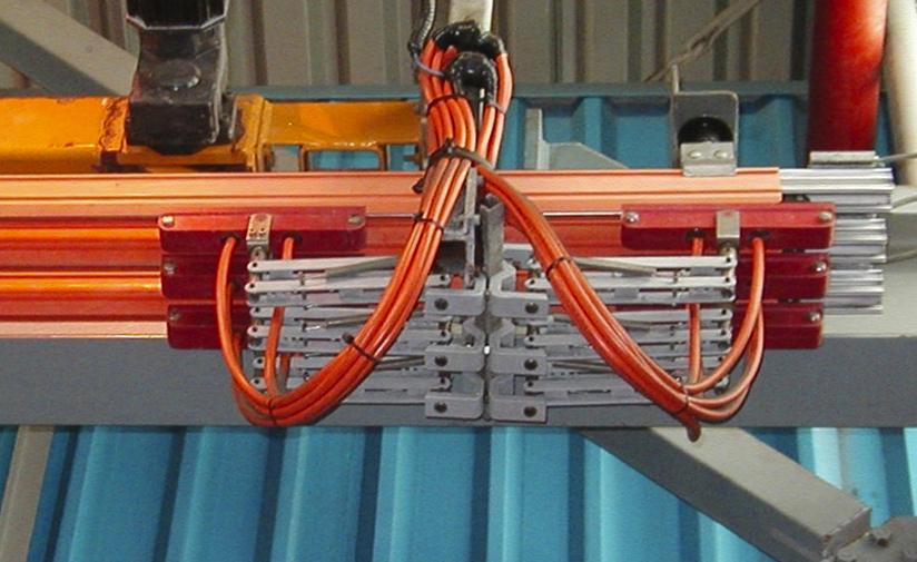
9 Hevi-Bar II Typical 4-Bar System For recommended hanger spacing, use chart at the right. For recommended hanger spacing, use chart at the right. 9
 Phase / Indoors (Orange) Ground / Indoors (Green) Phase & Ground / Outdoors UV Stable (Black) Phase & Ground / Indoors & Outdoors (Red) Conductor Bar")
10 Hevi-Bar II - 500A Conductors Standard Conductor Bar and Components Type / Max Temp. PVC 160 O F Poly - carbonate 250 O F Use (Color) Phase / Indoors (Orange) Ground / Indoors (Green) Phase & Ground / Outdoors UV Stable (Black) Phase & Ground / Indoors & Outdoors (Red) Conductor Bar Conductor Bar Cut Lgth (Specify 5 to 29 ft) Expansion Section Splice Power Feed Power Interrupting Section u End Cover E N/A B Wt lb (kg) 25.0 (11.34).81 lb/ft. (.112 kg/m) 30.0 (13.61) 1.5 (0.681) 4.0 (1.814) 45.0 (20.41) 1.0 (0.454) Length ft (m) 30.0 (9.114) Q 30.0 (9.114) / / 30.0 (9.114) u See Appendix IV Pgs / Conductor Bar Dura-Coat Conductor Bar with Splice End Cover Expansion Sections and Power Feed Expansion Sections are required at all structural expansion joints and for all systems greater than 390 ft ( m). See table above for expansion and power feed part numbers. Customer Supplied Lug Expansion Section Power Feed 10
11 Hevi-Bar II - 500A DURA-COAT & Hangers DURA-COAT Conductor Bar & Components The ideal option for highly corrosive environoments. Splices are preinstalled on Dura-Coat conductors. Type / Max Temp. PVC 160 O F Polycarbonate 250 O F Use (Color) Phase / Indoors (Orange) Ground / Indoors (Green) Phase & Ground / Outdoors UV Stable (Black) Phase & Ground / Indoors & Outdoors (Red) Conductor Bar Wt lb (kg) 25.0 (11.34) Conductor Bar Cut Lgth (Specify 5 to 29 ft) Expansion Section Splice Power Feed Power Interrupting Section u End Cover J J J J G-J J 39741G-J N/A B-J J 39741B-J B-J J J J J lb/ft ( kg/m) 30.0 (13.61) 1.5 (0.68) 4.0 (1.81) 45.0 (20.41) Length ft (m) 30.0 (9.144) (9.144) / / 30.0 (9.144) / 1.0 (0.454) u See Appendix IV Pgs Hangers Hangers can be installed on brackets up to 3/8 thick (9.5mm). Hangers with cross bolts can be used as anchors. 500 A Hangers Plated Hardware Stainless Steel Hardware Wt lb (kg) Polycarbonate Snap-In (0.136) Polycarbonate Snap-in w/insulator (0.404) Stainless Steel Cross Bolt (0.268) Stainless Steel Cross Bolt w/insulator (0.513) Polycarbonate Snap-In Polycarbonate Snap-in w/insulator Stainless Steel Cross Bolt Stainless Steel Cross Bolt w/insulator 11
 Phase / Indoors (Orange) Ground / Indoors (Green) Phase & Ground / Outdoors UV Stable (Black) Phase & Ground / Indoors &")
12 Hevi-Bar II - 700A Conductors Standard Conductor Bar and Components PVC 160 O F Type / Max Temp. Poly Carbonate 250 O F Fiberglass Reinforced Polyester 400 O F Use (Color) Phase / Indoors (Orange) Ground / Indoors (Green) Phase & Ground / Outdoors UV Stable (Black) Phase & Ground / Indoors & Outdoors (Red) Phase & Ground / Indoors (Orange) Conductor Bar Conductor Bar Cut Lgth (Specify 5 to 29 ft) Expansion Section Splice Power Feed Power Interrupting Section u End Cover B B N/A B C D Wt lb (kg) 40.0 (18.14) 1.31 lb/ft ( kg/m) 50.0 (22.68) 3.0 (1.36) 5.0 (2.27) 70.0 (31.75) 2.0 (0.91) Length ft (m) 30.0 (9.114) Q 15.0 (4.572) / / 30.0 (9.114) / u See Appendix IV Pgs Conductor Bar Expansion Sections and Power Feed Dura-Coat Conductor Bar with Splice End Cover Expansion Sections are required at all structural expansion joints and for all systems greater than 390 ft ( m). See table above for expansion and power feed part numbers. Customer Supplied Lug 12 Expansion Section Power Feed
13 Hevi-Bar II - 700A DURA-COAT & Hangers DURA-COAT Conductor Bar & Components The ideal option for highly corrosive environoments. Splices are preinstalled on Dura-Coat conductors. Type / Max Temp. PVC 160 O F Poly - carbonate 250 O F Use (Color) Phase / Indoors (Orange) Ground / Indoors (Green) Phase & Ground / Outdoors UV Stable (Black) Phase & Ground / Indoors & Outdoors (Red) Conductor Bar Wt lb (kg) 40.0 (18.14) Conductor Bar Cut Lgth (Specify 5 to 29 ft) Expansion Section Splice Cover Power Feed Power Interrupting Section u End Cover J J J J G-J J 50739B-J N/A B-J J J B-J J J J J lb/ft ( kg/m) 50.0 (22.68) 3.0 (1.361) 5.0 (2.268) 70.0 (31.75) 2.0 (0.907) Length ft (m) 30.0 (9.114) (4.57) 1.5 (0.457) 1.5 (0.457) 30.0 (9.114) 1.5 (0.457) u See Appendix IV Pgs Hangers Hangers can be installed on brackets up to 3/8 thick. Hangers with cross bolts can be used as anchors. Polycarbonate Snap-In 700 A Hangers Plated Hardware Stainless Steel Hardware High Temp. Wt lb (kg) Polycarbonate Snap-In N/A 0.28 (0.127) Polycarbonate Snap-in w/insulator B N/A 0.87 (0.395) Stainless Steel Cross Bolt (0.277) Stainless Steel Cross Bolt w/insulator (0.526) Polycarbonate Snap-in w/insulator Stainless Steel Cross Bolt Stainless Steel Cross Bolt w/insulator 13
14 Hevi-Bar II A Conductors Standard Conductor Bar and Components Type / Max Temp. PVC 160 O F Poly - carbonate 250 O F Fiberglass Reinforced Polyester 400 O F Use (Color) Phase / Indoors (Orange) Phase & Ground / Outdoors UV Stable (Black) Phase & Ground / Indoors & Outdoors (Red) Phase & Ground / Indoors (Orange) Conductor Bar Wt (lb) 85 (38.56) Conductor Bar Cut Lgth (Specify 5 to 29 ft) Expansion Section Splice Power Feed Power Interrupting Section u End Cover B 23500D C B 33796B D B lb/ft (.3871 kg/m) 70 (31.75) 3.5 (1.588) 6.5 (2.948) 105 (47.63) Length (ft.) / / 30.0 / 1.5 (0.680) u See Appendix IV Pg Conductor Bar Expansion Sections and Power Feed Dura-Coat Conductor Bar with Splice End Cover Expansion Sections are required at all structural expansion joints and for all systems greater than 390 ft ( m). See table above for expansion and power feed part numbers. Customer Supplied Lug Expansion Section Power Feed 14
 Phase / Indoors (Orange) Phase & Ground / Outdoors UV Stable (Black) Phase & Ground / Indoors & Outdoors (Red) Conductor Bar Wt ib (kg) 85 (38.")
15 Hevi-Bar II A DURA-COAT & Hangers DURA-COAT Conductor Bar & Components The ideal option for highly corrosive environoments. Splices are preinstalled on Dura-Coat conductors. Type / Max Temp. PVC 160 O F Poly - carbonate 250 O F Use (Color) Phase / Indoors (Orange) Phase & Ground / Outdoors UV Stable (Black) Phase & Ground / Indoors & Outdoors (Red) Conductor Bar Wt ib (kg) 85 (38.56) Conductor Bar Cut Lgth (Specify 5 to 29 ft) Expansion Section Splice Cover Power Feed Power Interrupting Section u End Cover J J J J 33796B 50736B-J J 50743B-J B-J 33796B J J J D J 33796B 2.8 lb/ft ( kg/m) 70 (31.75) 3.5 (1.59) 6.5 (2.95) 105 (47.63) Length ft (kg) 30 (9.114) Q 20 (6.096) / / 30 (9.114) / 1.5 (0.68) u See Appendix IV Pgs Hangers Hangers can be installed on brackets up to 3/8 thick. Hangers with cross bolts can be used as anchors A Hangers Plated Hardware Stainless Steel Hardware High Temp. Wt ib (kg) Polycarbonate Snap-In N/A 0.28 (0.127) Polycarbonate Snap-in w/insulator B N/A 0.87 (0.395) Stainless Steel Cross Bolt (0.277) Stainless Steel Cross Bolt w/insulator (0.526) Polycarbonate Snap-In Polycarbonate Snap-in w/insulator Stainless Steel Cross Bolt Stainless Steel Cross Bolt w/insulator 15
 Phase / Indoors (Orange) Phase & Ground / Outdoors UV Stable (Black) Phase & Ground / Indoors & Outdoors (Red) Conductor Bar Conductor Bar Cut Lgth")
16 Hevi-Bar II A Conductors Standard Conductor Bar and Components Type / Max Temp. PVC 160 O F Poly - carbonate 250 O F Use (Color) Phase / Indoors (Orange) Phase & Ground / Outdoors UV Stable (Black) Phase & Ground / Indoors & Outdoors (Red) Conductor Bar Conductor Bar Cut Lgth (Specify 5 to 29 ft) Expansion Section Splice Power Feed Power Interrupting Section u End Cover B 24000C B 33796B C B Wt lb (kg) 110 (49.90) 3.6 lb/ft ( kg/m) 88 (39.92) 4.0 (1.81) 130 (58.97) (58.97) Length ft (m) 30 (9.114) - 20 (6.10) / / 30 (9.114) / u See Appendix IV Pgs (0.680) Conductor Bar Dura-Coat Conductor Bar with Splice End Cover Expansion Sections and Power Feed Expansion Sections are required at all structural expansion joints and for all systems greater than 390 ft ( m). See table above for expansion and power feed part numbers. Customer Supplied Lug Expansion Section Power Feed 16
 Phase / Indoors (Orange) Phase & Ground / Outdoors UV Stable (Black) Phase & Ground / Indoors & Outdoors (Red) Conductor Bar Wt lb (m) 110 (49.")
 88 (39.92) 4.0 (1.81) 130 (58.97) 130 (58.97) Length ft (m) 30.0 (9.144) - 20.0 (6.")
 Polycarbonate Snap-In 23223 28220 0.28 (0.127) Polycarbonate Snap-in w/insulator 24902 24902B 0.87 (0.")
17 Hevi-Bar II A DURA-COAT & Hangers DURA-COAT Conductor Bar & Components The ideal option for highly corrosive environoments. Splices are preinstalled on Dura-Coat conductors. Type / Max Temp. PVC 160 O F Poly - carbonate 250 O F Use (Color) Phase / Indoors (Orange) Phase & Ground / Outdoors UV Stable (Black) Phase & Ground / Indoors & Outdoors (Red) Conductor Bar Wt lb (m) 110 (49.90) Conductor Bar Cut Lgth (Specify 5 to 29 ft) Expansion Section Splice Cover Power Feed Power Interrupting Section u End Cover J J J J 33796B 50734B-J J 50742B-J B-J 33796B J J J 51297B 50227C J 33796B 3.6 lb/ft ( kg/m) 88 (39.92) 4.0 (1.81) 130 (58.97) 130 (58.97) Length ft (m) 30.0 (9.144) (6.10) / / 30.0 (9.144) 1.5 (0.68) u See Appendix IV Pgs / Hangers Hangers can be installed on brackets up to 3/8 thick. Hangers with cross bolts can be used as anchors A Hangers Plated Hardware Stainless Steel Hardware Wt lb (kg) Polycarbonate Snap-In (0.127) Polycarbonate Snap-in w/insulator B 0.87 (0.395) Stainless Steel Cross Bolt (0.277) Stainless Steel Cross Bolt w/insulator (0.526) Polycarbonate Snap-In Polycarbonate Snap-in w/insulator Stainless Steel Cross Bolt Stainless Steel Cross Bolt w/insulator 17

 DURA-COAT Collector with Shoe. 50205 3.87 (1.755) Replacement Shoe for Standard or DURA-COAT 30516 1.00 (0.454) 250A Tandem Collector 21 long pigtails, 8 AWG, are supplied on the collector.")
 DURA-COAT Collector with Shoe. 39752 7.39 (3.352) Replacement Shoe for Standard or DURA-COAT (Two required per collector) 30516 1.00 (.")
18 Hevi-Bar II Collectors & Replacement Shoes All collectors include long-wearing copper graphite shoes (in holders) and pigtail wiring as noted below. For recommendations about choosing collectors, see Appendix I Pgs A Single Collector 21 long pigtails, 8 AWG, are supplied on the collector. Customer supplied wiring connects to the collector pigtail with in-line connectors. Used on 500A conductor bar only. TYPE Part No. Wt lb (kg) Standard Collector with Shoe (1.529) DURA-COAT Collector with Shoe (1.755) Replacement Shoe for Standard or DURA-COAT (0.454) 250A Tandem Collector 21 long pigtails, 8 AWG, are supplied on the collector. Customer supplied wiring connects to the collector pigtail with in-line connectors. Used on 500A conductor bar only. TYPE Part No. Wt lb (kg) Standard Collector with Shoe (2.898) DURA-COAT Collector with Shoe (3.352) Replacement Shoe for Standard or DURA-COAT (Two required per collector) (.454) 200A Single Collector 42 long pigtails, 2 AWG, are supplied on the collector. Customer supplied wiring connects to the collector pigtail with in-line connectors. Used on 700A A conductor bar only. Note that the 300A version is the same as the 200A, except with an extra tension spring on the arm. TYPE Part No. Wt lb (kg) Standard Collector with Shoe (3.116) DURA-COAT Collector with Shoe (3.343) 300A Standard Collector with Shoe Q 7.47 (3.388) Replacement Shoe for Standard & DURA-COAT 11417X 0.38 (0.172) 400A Tandem Collector 42 long pigtails, 2 AWG, are supplied on the collector. Customer supplied wiring connects to the collector pigtail with in-line connectors. Used on 700A A conductor bar only. Note that the 600A version is the same as the 400A, except with one extra tension spring on each arm. TYPE Part No. Wt lb (kg) Standard Collector with Shoe (6.078) DURA-COAT Collector with Shoe (6.305) 600A Standard Collector with Shoe B (51.75) Replacement Shoe for Standard & DURA-COAT (Two required per collector) 11417X 0.38 (0.172) 18
 Bracket with four pre-installed hangers - standard")
19 Hevi-Bar II 500A Support Brackets The Hevi-Bar II Support Brackets listed below are for 500A conductors. They are available in three types as listed below and can be ordered in five different configurations: Bracket only (no hangers included) Bracket with four pre-installed hangers - standard Polycarbonate Bracket with four pre-installed hangers - standard Polycarbonate w/insulators Bracket with four pre-installed hangers - stainless steel cross-bolt Bracket with four pre-installed hangers - stainless steel cross-bolt w/insulators All holes to accept hangers are 3 on-center and.56 diameter (to accept 3/8 diameter hanger bolts). Web Bracket Mounts to vertical web of beam. Bracket is 2 1/2 wide by 3/8 thick. Bracket Finish Dim X inches (mm) Dim Y Inches (mm) Part No. Bracket Only Wt lb (kg) Standard Polycarbonate Part Nos. - With Four Hangers Pre-Installed Standard Polycarbonate w/insulators Stainless Steel Cross-Bolt Stainless Steel Cross-Bolt w/insulator Plated Steel 6.0 (152) (413) (2.087) B 29440C 29440D Plated Steel 9.0 (229) (489) (2.359) B 51785C 51785D Plated Steel 11.0 (279) (540) (2.495) B 38268C 38268D Stainless Seel 9.0 (229) (489) (2.359) B 51786C 51786D Hot Dip Galv. 9.0 (229) (489) (2.359) B 34814C 34814D Web (29440) 2.0 (51) 3.0 (76) 3.0 (76) 6.0 (152) Flange (30493) Flange Bracket Mounts to top flange of beam. Bracket is a 2 x 2 angle, by 3/8 thick. The first hole is 1 1/4 from the end. Bracket Finish Dim X Inches (mm) Dim Y Inches (mm) Part No. Bracket Only Wt lb (kg) Standard Polycarbonate Part Nos. - With Four Hangers Pre-Installed Standard Polycarbonate w/insulators Stainless Steel Cross-Bolt Stainless Steel Cross-Bolt w/insulator Plated Steel (337) (597) (3.992) B 30493C 30493D 19
20 Hevi-Bar II 700A-1000A-1500A Support Brackets The Hevi-Bar II Support Brackets listed below are for 700A, 1000A, or 1500A conductors. They are available in three types as listed below, and can be ordered in five different configurations: Bracket only (no hangers included) Bracket with four pre-installed hangers - standard Polycarbonate Bracket with four pre-installed hangers - standard Polycarbonate w/insulators Bracket with four pre-installed hangers - stainless steel cross-bolt Bracket with four pre-installed hangers - stainless steel cross-bolt w/insulators All holes to accept hangers are 3 on-center and.56 diameter (to accept 3/8 diameter hanger bolts). Web Bracket Mounts to vertical web of beam. Bracket is 2 1/2 wide by 3/8 thick. Bracket Finish Dim X Inches (mm) Dim Y Inches (mm) Part No. Bracket Only Wt (lb) Standard Polycarbonate Part No. - With Four Hangers Pre-Installed Standard Polycarbonate w/insulators Stainless Steel Cross-Bolt Stainless Steel Cross-Bolt w/insulator Plated Steel 6.0 (152) (413) B 32893C 32893D Plated Steel 9.0 (229) (489) B 39923C 39923D Stainless Seel 9.0 (229) (489) B 51788C 51788D Hot Dip Galv. 9.0 (229) (489) B 32932C 32932D 2.0 (51) Web (32893) 3.0 (76) 6.0 (152) 3.0 (76) Flange (51878) Flange Bracket Mounts to top flange of beam. Bracket is a 2 x 2 angle, by 3/8 thick. The first hole is 1 1/4 from the end. Bracket Finish Dim X Inches (mm) Dim Y Inches (mm) Part No. Bracket Only Wt (lb) Standard Polycarbonate Part Nos. - With Four Hangers Pre-Installed Standard Polycarbonate w/insulators Stainless Steel Cross-Bolt Stainless Steel Cross-Bolt w/insulator Plated Steel (337) (597) B 51878C 51878D 20
 Standard Polycarbonate Part Nos.")
 Braced Web (25691) Lateral (51876) 2.25 (57) Lateral Bracket Mounts to vertical web of beam to configure conductor bar one above the other.")
21 Hevi-Bar II 700A-1000A-1500A Support Brackets Braced Web Bracket Single-iron weldment, used for heavier conductor bar (e.g. 1500A) Bracket Finish Dim X Inches (mm) Dim Y Inches (mm) Part No. Bracket Only Wt (lb) Standard Polycarbonate Part Nos. - With Four Hangers Pre-Installed Standard Polycarbonate w/insulators Stainless Steel Cross-Bolt Stainless Steel Cross-Bolt w/insulator Plated Steel 11.0 (279) 21.0(533) B 25691C 25691D 20.0 (508) Braced Web (25691) Lateral (51876) 2.25 (57) Lateral Bracket Mounts to vertical web of beam to configure conductor bar one above the other. Bracket is 2 1/2 wide by 3/8 thick. Bracket Finish Dim X Inches (mm) Dim Y Part No. Bracket Only Wt (lb) Standard Polycarbonate Part Nos. - With Four Hangers Pre-Installed Standard Polycarbonate w/insulators Stainless Steel Cross-Bolt Stainless Steel Cross-Bolt w/insulator Plated Steel 1.50 (38) 12.0 (305) B 51876C 51876D 21
22 Hevi-Bar II Specifications Conductor Bar Cover Cover Type: Standard (Ground) UV Resistant Medium Heat Hi HeatQ Bare Bar Material PVC PVC Lexan Polycarbonate Fiberglass Reinforced Color Orange (Green) Black Red Orange no color Normal Ambient Q 700A and 1000A only F to 104 O F -40 O C to 40 O C -40 O F to 104 O F -40 O C to 40 O C -40 O F to 200 O F -40 O C to 93.3 O C -40 O F to 345 O F -40 O C to O C N/A -40 O F to 690 O F -40 O C to O C Max. Temperature 160 O F (71.1 O C) 160 O F (71.1 O C) 250 O F (121.1 O C) 400 O F (204.4 O C) 750 O F (398.8 O C) Material PVC PVC Lexan Polycarbonate Fiberglass Dielectric Strength 450 volts/mil 450 volts/mil 600 volts/mil 200 volts/mil N/A Volume Resistivity >10 12 ( /mil) >10 12 ( /mil) >10 13 ( /mil) >10 11 ( /mil) N/A Flame Test Self Extinguishing Self Extinguishing Self Extinguishing Self Extinguishing N/A Specific Density 1.5 g/cm g/cm g/cm g/cm 3 N/A N/A Conductor Bar Nominal Current of Bar: 500A 700A 1000A 1500A Cross Sectional Area, in. (mm) 0.45 (11.4) 0.70 (17.8) 1.05 (26.7) 2.29 (58.2) AC & DC Voltage / / /4160 DC Resistance at 20 O C ( /ft.) 3.27 x x x x 10-5 Phase Corrected Impedance Z at 20 O C ( /ft.) 5.40 x x x x 10-5 Conductor Length, ft. (m) 30.0 (9.1) 30 feet (9.1) 30 feet (9.1) 30 feet (9.1) Support Spacing, ft. (m) 5 (1.52) 7.5 (2.28) 10 (3.05) 10 (3.05) Spacing between Conductors, in. (mm) 3.0 (76.2) 3.0 (76.2) 3.0 (76.2) 3.0 (76.2) Expansion Sections not required for runs less than: ft. (m) 390 (11.9) 390 (11.9) 390 (11.9) 390 (11.9) Minimum Bending Radius, ft. (m) 8.0 (2.4) 10.0 (3.05) 12.0 (3.7) 15.0 (4.6) Corrosion Protection Hardware Type: Zinc Plated Stainless Steel DURA-COAT Duty Moderate Severe Extreme Duty Available Accessories (Contact Conductix-Wampfler) Thermostatically controlled heater wire system, for ice and snow environments (500A only) Transfer Caps for switches Pick-up Guides for discontinuous systems Vertical and horizontal curves The appropriate conductor bar can be chosen only when all the relevant factors are known. Please refer to the Specification Data Sheet on Pg. 6, and to Appendices I through IV at the back of this catalog. Also, please consult Conductix-Wampfler Sales if you have any questions about the suitability of this product to your application. 22
23 Hevi-Bar II Installed Dimensions 500A - Standard Hanger 500A - with Insulators Contact Surface 1.63 ( 41) 5.50 (140) Contact Surface 4.50 (114) 5.50 (140) 3.0 (76) Typ 700A - Standard Hangers 3.0 (76) Typ 700A - with Insulators Contact Surface 1.75 (45) 6.0 (152) 4.63 (118) Contact Surface 6.00 (152) 3.0 (76) Typ 1000A - Standard Hangers 3.0 (76) Typ 1000A - with Insulators Contact Surface 2.25 (57) 6.00 (152) Contact Surface 5.13 (130) 6.00 (152) 3.0 (76) Typ 1500A - Standard Hangers 3.0 (76) Typ 1500A - with Insulators Contact Surface 3.13 (80) 6.00 (152) Contact Surface 6.00 (152) 6.00 (152) 3.0 (76) Typ 3.0 (76) Typ 23
24 Hevi-Bar II Bar & Expansion Dimensions Bar Profiles 500A 700A 1000A 1500A 1.42 (36) 1.50 (38) 1.50 (38) 1.50 (38) 1.55 (39) 2.25 (57) 2.75 (70) 3.37 (86) 500A Expansion Section (37677) ( 495) 2.60 (66) 3.73 (95) (29.1m) closed / 30-2 (9.20m) open 700A Expansion Section (50739) (921) 2.50 (64) 4.63 (118) ( 4.5m) closed / 15-2 (4.6m) open 1000A Expansion Section (23512) (914) REF 2.50 (64) 2.50 REF (130) REF 19'-10" (6.0M) REF CLOSED closed / 20-2 / 20'-2" (6.1M) REF openopen 1500A Expansion Section (32820) ( 923) 2.51 (64) 5.78 (147) (6.0M) closed / 20-2 (6.1M) open 24
25 Hevi-Bar II Splice Dimensions 500A Splice (37676), 1/4 Bolts, Torque to 6-8 ft-lb 2.60 (66) 6.00 (152) 3.73 (95) (279) 700A Splice (38115), 5/16 Bolts, Torque to ft-lb 2.60 (66) 7.55 (192) 4.64 (118) (368) 1000A Splice (37746), 5/16 Bolts, Torque to ft-lb 2.60 (66) 5.11 (130) ( 267) (432) 1500A Splice (38968), 5/16, Torque to ft-lb 2.60 (66.0) (266.7) 5.81 (147.6) (571.5) 25
26 Hevi-Bar II Power Feed Dimensions 500A Power Feed (37674), 1/4 Bolts on 1 Centers, 6-8 ft-lb 2.60 (66) Cable Supplied by others 3.88 (99) 2.75 (70) 8.63 (219) 700A Power Feed (38117), 5/16 Bolts on 1 Centers, ft-lb 2.60 (66) Cable Supplied by others (300) 2.61 (66) Cable Supplied by others 4.64 (118) 1000A Power Feed (38184), 5/16 Bolts on 1 Centers, ft-lb 2.60 (66) Cable Supplied by others (300) 5.75 (146) Cable Supplied by others 5.13 (130) 1500A Power Feed (50227), 5/16 Bolts on 1 Centers, ft-lb 2.60 (66) Cable Supplied by others Cable Supplied by others 5.74 (146) 9.50 (241) (406) 1500A Power Feed (28470), 5/16 Bolts on 1 Centers, 20 ft-lb 2.49 (63) 2.49 REF Cable Supplied by others (406) REF 1.00 REF (25) Cable Supplied by others (63) REF (203) REF 26
27 Hevi-Bar II Power Interrupting Section Dimensions 500A Power Interrupting Section (50746) 5 (1.5M) 15 (4.6M) (.76M) (.76M) 5 (1.5M) (3M) (3M) (3M) 1.0 (25) 1.0 (25) Gap Gap 2.75 (70) 30 (9.1M) 700A Power Interrupt (50748) 15 (4.6M) (.58M) (.76M) (.76M) (.58M) (2.3M) 1.0 (25) Gap (4.5M) 30 (9.1M) 1.0 (25) Gap (2.3M) 5.50 (140) 1000A Power Interrupt (50755) (.76M) 12 (3.7M) (.76M) (.76M) (.76M) 10 (3M) (3.5M) 1.00 (25) Gap 30 (9.1M) 1.00 (25) Gap (2.5M) 5.75 (146.1) 1500A Power Interrupt (50760) 12 (3.7M) (.76M) (.76M) (.76M) (.76M) 10 (3M) 1.00 (25) Gap (3.5M) (2.5M) 1.00 (25) Gap 30 (9.1M) 9.50 (241.3) 27
28 Hevi-Bar II End Cover Dimensions 500A End Cover (27588) (76.2) REF (38.1) REF (122) REF 700A End Cover (50859) 3.00 (76.2) 1.50 (38.1) 8.2 (208.3) 1000A End Cover (33796B) 2.8 (71.1) 1.5 (38.1) 9.5 (241.3) 1500A End Cover (33796B) 2.8 (71.1) 1.5 (38.1) 9.5 (241.3) 28
29 Hevi-Bar II Collector Dimensions 125A Single Collector Q (30388/50205) (359) 1.50 (38.1) 1.50 (38.1) contact surface 2.75 (70) Up 2.75 ( 70) Down 5.50 (139.8) 7.63 (194) Wear Line 250A Tandem Collector Q (30389/39752) 1.50 (38.1) 1.50 (38.1) (717.6) Wear Line 2.75 (70) up Contact Surface 2.75 (70) down 5.50 (139.8) 7.63 (193.9) Q Only for use with 500A Conductor Bar 29
30 Hevi-Bar II Collector Dimensions 200A & 300A Single Collector (24060 / / 24060Q) 2.50 (63.6) REF 2.50 (63.6) REF (393.7) 2.75 (69.9) UP Up REF REF CONTACT Contact SURFACE Surface 2.75 (69.9) DOWN Down REF 6.00 (152.4) REF 2.13 (54.1) REF 400A & 600A Tandem Collector (24061 / / 24061B) 2.50 (63.6) 2.50 REF 2.50 (63.6) 2.50 REF (787.4) REF 2.75 (69.9) UP Up REF CONTACT Contact SURFACE Surface DOWN (69.9) REF Down 6.00 (154.2) REF 2.13 (54.1) REF Q Only for use with 700A, 1000A & 1500A Conductor Bar 30
31 Appendix I - Selection of Systems Carefully review your equipment and application to chose the correct system and reduce the risk of system failures, equipment downtime, and maintenance time and expense. There are eight interrelated factors that should be considered when selecting the correct system. Environmental Conditions Have all aspects of the operating environment been accounted for? Freezing Conditions - Might require a heater wire to keep the conductor contact surface free from ice. Water and/or Dust - Might adversely affect components and might require the use of insulated hangers to better isolate the live conductors from ground. Chemicals Can adversely affect system components. Acidic or basic fumes may require stainless steel hardware and components. With the Hevi-Bar II system, you may want to consider the optional Dura-Coat treatment to reduce component corrosion (Pgs. 37, 39, 41, 44). Cutting Oils May negatively affect polycarbonate components Radiation - May require the use of non-pvc components and non-galvanized plated components. Mounting and Installation How will your system be mounted? Bottom Entry Puts the running surface on the bottom side of the conductor, which keeps dust, water, or debris away. Lateral (or side) Entry Can be used if space is limited. Lateral mounting is not recommended for dusty, outdoor, or wet conditions. You may be able to stagger the collectors to decrease the space required for the system. Installation Collector Arms are designed to accommodate a certain amount of movement or misalignments between the crane/ vehicle and the conductor. However, if misalignments are excessive the collector could disengage from the bar. Poor collector installation is the single greatest cause of new system problems. Installation Instructions should be strictly followed to optimize system performance and prevent problems. Manuals are available at Number of Power and Bonding Conductors Required Have you ordered enough conductor runs? Power Legs - Each power leg requires one run of bar Bonding (Ground) Bar - Per article (National Electrical Code): The trolley frame and bridge frame shall not be considered as electrically grounded through the bridge and trolley wheels and its respective tracks. A separate bonding conductor shall be provided. A bonding bar is required for all overhead cranes built after Moving Versus Stationary Applications Is the equipment moving or stationary when operating? Moving Machine - Draws maximum power as it moves. Current-induced heat is dissipated over a wider area of the conductor. Stationary Machine - Draws maximum power while stationary for extended periods (e.g.: weld stations, testing equipment, or cranes that repeatedly lift in the same location). Current-induced heat is not easily dissipated when collectors are stationary. In these cases, verify that the collectors and conductors are adequate for the application. Current and Voltage Requirements The purchase of a new conductor system affords the opportunity to size the system for additional cranes or larger cranes that may be added in the future. A small investment now could avoid major investments in the future. Conductor Bar Rating Per NEC Article , the bar must accommodate 100% of the current of all the largest motors involved in a single movement, plus 50% of the next largest motors. The auxiliary hoist motor must be included if it works in conjunction with the main hoist. The system also must accommodate 100% the current draw of auxiliary equipment such as magnets, lighting, air conditioners, etc. that operate when the largest motors are energized. Multiple Cranes on a Single Runway Sum the amperage requirements of each crane, then apply the appropriate diversity factor (NEC Table e). All cranes do not pull the maximum load all the time or pull the load at the same time. Two Cranes Working in Tandem - Do not apply the diversity factor, since both run at the same time. See Specification Data Sheet, Pg. 6-7 for further total load calculation details. 31
 and higher. The conductor system may need to meet the fault force requirements as determined by a qualified engineer.")
 recommends a maximum volt age drop of 3% on runways and 2% on bridges.")

32 Appendix I - Selection of Systems Voltage Rating volt rated insulating covers are standard. Higher voltages require covers designed for that voltage. Conductor separation may also be affected for medium voltage (e.g volts) and higher. The conductor system may need to meet the fault force requirements as determined by a qualified engineer. Voltage Drop and Power Feed Locations Voltage drop along a conductor increases as system length increases and as ambient temperature increases. Maximum Voltage Drop - The CMAA (Crane Manufacturers Association of America) recommends a maximum volt age drop of 3% on runways and 2% on bridges. The voltage drop in volts will vary according to voltage available. For example, a 3% voltage drop on a 480 volt system is volts; a 3% voltage drop at 115 volts is 3.45 volts. Center Power Feed - Is the optimal location for most systems. Longer runs may require multiple power feed locations to compensate for voltage drop and to minimize the total cost of the system. Multiple Power Feeds - Can reduce total system cost if the savings of a lower capacity bar offsets the cost to install the multiple power feed locations. Calculating Voltage Drop - Use Conductix-Wampfler Quick Quote (see Pg. 5) to automate this calculation, as shown in the examples below. Voltage drop can also be manually calculated see Appendix II, Pg. 61. Figure 1 Center Feed Example: Voltage drop along a 500 foot long runway with one crane drawing 500 amps at 460 volts on a 500 amp rated bar. The green line shows the voltage drop along the run at 0 O F. The blue line shows the voltage drop at 110 O F. The red line indicates the 3% maximum voltage drop. The voltage drop increases linearly as you move away from the center feed point. Figure 2: - Same parameters as Fig. 1, except with a 1000 foot system. Note that the voltage drop is now greater than the recommended 3%. Figure 3: Center Power Example: With higher capacity 1500 amp bar to lower the voltage drop below 3%. Figure 4: Two power feeds optimally located. The voltage drop remains under 3%, without the need to increase conductor capacity. A load positioned between the two feed points is supplied by both power feeds. 32
33 Appendix I - Selection of Systems Thermal Expansion/Contraction and Other Effects of Heat The effects of thermal expansion and contraction become more pronounced as the length of the run increases. The combination of ambient heat plus current-induced heat affects the size of conductor bar needed, the power feed arrangement, and the type of insulating cover required. Snaking Occurs when the conductors heat up, and due to cumulative hanger friction, start to bow to the side. This can be observed by sighting down the runway. Each bar will bow alternately left and right between hangers, which puts strain on the collectors and hangers. Eventually, the collectors can disengage and damage the system. Snaking - Older Systems - May begin after a year or two in operation. This is because accumulated dirt increases friction between bar and hangers. This possibility should be considered when determining the number of expansions. Precautions taken at the time of installation could avoid costly repairs later. Shorter Systems - Can be anchored in the center. As the temperature of the conductor rises, the expansion simply pushes the bar outward. The longest system that can be successfully center-anchored depends on the friction of the hangers and the rigidity of the conductor. Longer Systems - Require the installation of one or more Expansion Sections - i.e: lengths of conductors designed to slide in and out to absorb bar expansion/contraction between anchor points. The slider is bridged by a jumper cable to maintain electrical continuity and acts as the running surface for the collector. Expansion sections effectively break the run into smaller lengths defined by the anchor points. The length of run an expansion section can accommodate is based on expansion/contraction parameters, including temperature range, conductor material, and the length of the slider. The high end of the temperature range is the sum of current-induced heat of the bar (at maximum load) plus the highest ambient temperature. The low end is the lowest ambient temperature, which may occur during a January system shutdown. Conductor sections need to be anchored properly between each expansion and between the last expansion and the end of the run. Ambient Heat All heat sources must be considered and evaluated for their effect on the conductor and cover. Typical heat sources are furnaces, billets, slag, etc. Ambient heat is easy to measure and the effects are consistent with measured values. Radiant Heat - Can be difficult to measure and its effects hard to anticipate. It will directly affect cover, and the cover might withstand it. However, the effect on metal components might be even more pronounced. For example, metal hangers may heat to such a degree that they will melt the cover. Heat shields provide a good way of minimizing the effects of radiant heat. If heat shields are not practical, higher temperature rated covers might be required. Total Operating Temperature The sum of the ambient temperature, radiant heat, and current-induced temperature rise. This is the total heat the conductor and its cover material must withstand. For example, if your machine is working in an ambient temperature of 120 O F (49 O C), and the current-induced temperature rise of the conductor adds another 50 O F, the total 170 O F (76.7 O C) exceeds the PVC cover rating of 70 O C (156 O F). The cover will deform or melt, and interfere with collector tracking and/or interrupt power. In this scenario, the cover must be made from a heat-resistant material. Conductix-Wampfler offers Medium Heat or High Heat covers for most systems see Pg. 4. Conductor Bar Current Rating and Duty Cycle Conductor Electrical Capacity A wide variety of capacities are offered, since conductors often power multiple vehicles. Ratings are based on the electrical load the conductor can handle before the operating temperature of the bar exceeds the temperature rating of its cover. The rating assumes a certain ambient temperature (e.g.: 49 O C or 120 O F) and a specific duty cycle. Duty Cycle - One manufacturer may rate their conductors for continuous duty; others for intermittent duty based on a given duty cycle. It is important to know which was used to establish the ratings. Continuous Duty - A conductor is put under a continuous load at some normal ambient, usually 30 O C. Once the bar temperature has stabilized at the target load rating, the bar temperature cannot exceed the temperature rating of the cover. Most PVC covers can handle approximately 70 O C, which is a 40 O C rise over 30 O C ambient. 33
34 Appendix I - Selection of Systems Intermittent Duty - Assumes that the current is on for a period of time and off for a period of time; i.e.: one duty cycle. The conductor is allowed to cool between on phases. A 50% duty cycle is most common i.e.: one minute on and one minute off. Since a crane cannot lift continuously, nor is current flowing at maximum for long periods of time, most operate at a 40% duty cycle or less. So a 50% duty cycle is sufficient. However, cranes that see heavy duty, especially Class D and E cranes (see end of this Appendix), may push the conductor beyond a 50% intermittent duty rating. Collector Electrical Capacity A limited selection of collector capacities is available, since collectors only power the crane/vehicle they service. Additional collectors can be used if the crane/vehicle load exceeds the collector rating. Note that the load will not be shared equally among multiple collectors. The collector closest to the power feed will carry a larger load than those farther down the line. So when using multiple sets of collectors, make sure the collector capacities are adequate for this scenario CMAA Crane Classifications Provided for general information only. er to CMAA Section 78-6 for full definitions. Class A (Standby or Infrequent Service) Performs precise lifts at slow speed, with long idle period between lifts. Performs lifts at full or near rated capacity. Power houses, public utilities, turbine rooms. Class B (Light Service) Light service requirements at slow speed. Performs 2 to 5 lifts/hour, light to occasional full loads, at 10 ft. average height. Repair shops, light assembly, service buildings, light warehousing. Class C (Moderate Service) Moderate service requirement with loads averaging 50% of capacity. 5 to 10 lifts per hour at 15 ft. average lift height. Not more that 50% of lifts at rated capacity. Machine shops, paper mill machine rooms, etc. Class D (Heavy Service) Bucket/magnet duty, where heavy duty production is required. Loads of 50% capacity handled constantly. 10 to 20 lifts per hour averaging 15 ft. lift height. Not over 65% of the lifts at rated capacity. Heavy machine shops, foundries, fabricating plants, steel warehouses, container yards, lumber mills, etc. Class E (Severe Service) Loads approaching capacity throughout the life of the crane. 20 or more lifts per hour at or near rated capacity. Magnet/bucket cranes for scrap yards, cement mills, lumber mills, fertilizer plants, container handling. Class F (Continuous Severe Service) Handles loads approaching capacity continuously under severe service conditions throughout the life of the crane. Includes custom designed specialty cranes performing work critical to the total production facility. Needs to have the highest reliability and ease of maintenance. For system recommendations based on Crane Class, contact Conductix-Wampfler Sales. 34
35 Appendix II - Voltage Drop Calculations Proper selection of conductor and covers for Conductix-Wampfler conductor systems is simple, requiring only the ampacity, voltage and ambient conditions. The method for determining the rating for cranes and hoists is completely outlined in NEC (e). Further reference to the Code is made where applicable. I. For a single crane, simply use the nameplate full load ampere rating of the largest motor or group of motors for any one function plus half the rating of the next largest motor or motor groups. Hoist = 65A x 1 = 65.0 Bridge = 27A x.5 = 13.5 Total 78.5A For multiple cranes, use the same method for each crane, add the results and multiply by the demand factor shown in table (e) NEC Book. Examples with data taken from motor nameplates - all are 460V, 3-phase, 60 Hz. Crane #1 Hoist = 65A x 1 = 65.0 Bridge = 27A x.5 = 13.5 Total 78.5A Crane #2 Hoist = 52A x 1 = 52.0 Bridge = 14A x.5 = 7.0 Total 59.0A Total of #1 + # x.195 = 130.0A II. When the motor ampere ratings are unknown, a good approximation may be made using the nominal horse power ratings of the motors, converting them to full load amperes per NEC table ; then proceed as above. If the motors are not three-phase, applicable tables through must be used. A few examples from the tables are: Full-Load Current (Three-Phase Alternating-Current Motors) HP 230V 460V 575V Full-Load Current in Amperes, Direct-Current Motors Armature Voltage Rating (Direct-Current) HP 240V HP 240V Voltage Drop Voltage drop is the difference between the voltage at the feed point and the voltage at the extreme end. It is usually expressed as a percentage of the supply voltage and can be calculated as shown below. Voltage drop increases in direct proportion to the length of the conductors. The CMAA specifications limit total voltage drops to 3% on runways and 2% on bridge conductors. Since power feeds are usually located at the mid-point of a system, the effective length is the distance from power feed to the end of the runway. On longer systems if may be necessary to provide additional feed points. Voltage Drop per 100 Ft. of Run Per 100A of Current Conductor Stainless Steel 40A Galvanized Steel 90A Galvanized Steel 110A Stainless Clad Copper 250A Copper Steel Laminate 250A Rolled Copper 350A Solid Copper 500A 3-Phase 60 Hz D.C % at Max Amps and Length from Power feed Bar Amps 480V 240V SS Galv Galv SS / CU CU / Galv Rolled Cu Solid Cu Example Rolled Copper 3-phase 350 long, 250A load. VD = 1.39 x 3.5 x 2.5 = 12.1 volts Assume load pf is 90 3% of 480V = % of 240V = 7.2 2% of 180V = 9.6 2% of 240V =
36 Appendix III Electrical Formulas & Conversions Electrical Formulas Ohms Law Ohms = volts amperes Amperes = volts ohms Volts = amperes x ohms Power Watts = amperes x volts Amperes = (not 3-Phase) HP = Power Factor = watts volts volts x amps x efficiency 746 watts amperes x volts 3-phase Kilowatts = 3-phase Amperes = 3-phase Volt-Amperes = Single-phase Kilowatts = Single-phase Amperes = volts x amperes x power factor x x HP (Horsepower) x volts x efficiency x power factor volts x amperes x volts x amperes x power factor x HP (Horsepower) volts x efficiency x power factor Speed Synchronous RPM = Hertz x 120 Percent Slip = poles Synchronous RPM - Full Load RPM Synchronous RPM x 100 Metric Conversion Formulas To Obtain: Calculate: Millimeters Inches x 25.4 Inches Millimeters x Meters Feet x.3048 Feet Meters x Square Centimeters Square Inches x 6.45 Square Inches Square Centimeters x Kilograms Pounds x Pounds Kilograms x Kilograms per Meter lb/ft (divided by).6719 Pounds per Foot kg/m x.6719 Degrees Celsius (Degrees F-32) x 5/9 Degrees Fahrenheit (Degrees C x 9/5)
37 Appendix IV - Power Interrupting Sections Power can be shut off in a designated area along a bar system, either to safely maintain vehicles, or for some other purpose, while leaving the rest of the system powered. The shut off zone can be configured at the end of or in the middle of the system using a Power Interrupting Section. The following diagrams show how this is set up. Note that Tandem Collectors can bridge across the isolation joint of an isolation section, so enough Power Feeds and Isolation Sections must be used to ensure correct power switching. End Power Interrupting Sections Safe-Lec 2: For each power phase order: Qty. 1 - Power Interrupting Section of the desired current rating (Pg. 21). With this kit you get the required isolations and power feeds. Qty. 1 - Customer supplied DPST switch per phase and necessary power wiring (ordered from others) Hevi-Bar II: For each power phase order: Qty. 1 - Power Interrupting Section of the desired current rating (Pgs ). With this kit you get the required isolations and power feeds. Qty. 1 - Customer supplied DPST switch per phase and necessary power wiring (ordered from others) KEY POWER FEED ISOLATION SPLICE TANDEM COLLECTOR POWERED AREA OF BAR NON-POWERED AREA OF BAR I: System with power off to the maintenance section (DPST switch open), but with tandem collector bridging the first (left-most) isolation joint. ISOLATION SWITCH-DPST (OPEN) (CUSTOMER SUPPLIED) POWERED ZONE 30.00" MIN. BUFFER ZONE MAINTENANCE ZONE II: System with power off to the maintenance section (DPST switch open), but with tandem collector fully to the right of the first (left-most) isolation joint. ISOLATION SWITCH-DPST (OPEN) (CUSTOMER SUPPLIED) POWERED ZONE 30.00" MIN. BUFFER ZONE MAINTENANCE ZONE III: System with power on to the maintenance section (DPST switch closed). ISOLATION SWITCH-DPST (CLOSED) ISOLATION (CUSTOMER SWITCH-DPST SUPPLIED) (CLOSED) (CUSTOMER SUPPLIED) POWERED ZONE 37
38 Appendix IV - Power Interrupting Sections Middle Power Interrupting Sections Safe-Lec 2: For each power phase order: Qty. 2 - Power Interrupting Section of the desired current rating (Pgs. 21). With this kit you get the required isolations and power feeds. Qty. 1 - Customer supplied TPST switch per phase and necessary power wiring (ordered from others) Hevi-Bar II: For each power phase order: Qty. 2 - Power Interrupting Section of the desired current rating (Pgs ). With this kit you get the required isolations and power feeds. Qty. 1 - Customer supplied TPST switch per phase and necessary power wiring (ordered from others) KEY POWER FEED ISOLATION SPLICE TANDEM COLLECTOR POWERED AREA OF BAR NON-POWERED AREA OF BAR I: System with power off to the maintenance section (TPST switches open), power will not feed into the maintenance zone. JOINT BETWEEN PWR INTER SECS. FOR HEVI-BAR II OR ISOLATION SECS. FOR SAFELEC 2 THIS POWERFEED ON HEVI-BAR II ONLY (NOT USED) ISOLATION SWITCH-TPST (OPE (CUSTOMER SUPPLIED) POWERED ZONE MAINTENANCE ZONE POWERED ZONE 30.00" MIN. - BUFFER ZONE POWER FEED (5) ISOLATION ZONE 30.00" MIN. - BUFFER ZONE II: System with power on (TPST switches closed), normal crane operation resumes with power to all zones. JOINT BETWEEN PWR INTER SECS. FOR HEVI-BAR II OR ISOLATION SECS. FOR SAFELEC 2 THIS POWERFEED ON HEVI-BAR II ONLY (NOT USED) ISOLATION SWITCH-TPST (CLOS (CUSTOMER SUPPLIED) POWERED ZONE 30.00" MIN. - BUFFER ZONE MAINTENANCE ZONE ISOLATION ZONE 30.00" MIN. - BUFFER ZONE POWERED ZONE 38
39 Appendix V Terms, Conditions, and Warranty The technical data and images which appear in this catalog are for informational purposes only. NO WARRANTIES, EXPRESSED OR IMPLIED, INCLUDING WARRANTIES OF MERCHANTABILITY OR FITNESS FOR A PARTICULAR PURPOSE, ARE CREATED BY THE DESCRIPTIONS AND DEPICTIONS OF THE PRODUCTS SHOWN IN THIS CATALOG. Conductix-Wampfler ( seller ) makes no warranty and assumes no liability as to the function of equipment or the operation of systems built according to customer design or of the ability of any of its products to interface, operate or function with any portions of customer systems not provided by Conductix-Wampfler. Seller agrees to repair or exchange the goods sold hereunder necessitated by reason of defective workmanship, and material discovered and reported to Seller within one year after shipment of such goods to Buyer. Except where the nature of the defect is such that it is appropriate in Seller s judgement to effect repairs on site, the seller s obligation hereunder to remedy defects shall be limited to repairing or replacing (at Seller s option), FOB point of original shipment by Seller, any part returned to Seller at the risk and cost of Buyer. Defective parts replaced by Seller shall become the property of Seller. Seller shall only be obligated to make such repair or replacement of the goods which have been used by Buyer in service recommended by Seller and altered only as authorized by Seller. Seller is not responsible for defects which arise from improper installation, neglect, or improper use or from normal wear and tear. Additionally, Seller s obligation shall be limited by the manufacturer s warranty (and shall not be further warranted by Seller) for all parts procured from others according to published data, specifications, or performance information not designed by or for Seller. Seller further agrees to replace, or at Seller s option to provide a refund of the sales price of any goods that did not conform to applicable specifications or which differ from that agreed to be supplied which non-conformity is discovered and forthwith reported to Seller within thirty (30) days after shipment to Buyer. Seller s obligation to replace or refund the purchase price for non-conforming goods shall arise once Buyer returns such good FOB point of original shipment by Seller at the risk and cost of Buyer. Goods replaced by Seller shall be come property of Seller. There is no guarantee or warranty as to anything made or sold by Seller, or any service performed, except as to title and freedom from encumbrances, and except as herein expressly stated and particularly without limiting the foregoing. There is no guarantee or warranty, express or implied, of merchantability or of fitness for any particular purpose or against claim of infringement or the like. Seller makes no warranty (and assumes no liability) as to function of equipment or operation of systems built to Buyer s design or of the ability of any goods to interface, operate or function with any portions of Buyer s system not provided by Seller. Seller s liability on any claim; whether in contract (including negligence) or otherwise, for any loss or damage arising out of, connected with, or resulting from the manufacture, sale, delivery, resale, repair, replacement or use of any products or, services shall in no case exceed the price paid for the product or services or any part thereof which give rise to the claim. In no event shall Seller be liable for consequential, special, incidental or other damages, nor shall Seller be liable in respect to personal injury or damage to property on the subject matter hereof unless attributable to gross misconduct of Seller, which shall mean an act of omission by Seller demonstrating reckless disregard of the foreseeable consequences thereof. Seller is not responsible for incorrect choice of models or where products are used in excess of their rated and recommended capacities and design functions or under abnormal conditions. Seller assumes no liability for loss of time, damage or injuries to property or persons resulting from the use of Seller s products. Buyer shall hold Seller harmless from all liability, claims, suits and expenses in connection with loss or damage resulting from operation of products or utilization of services, respectively, of Seller and shall defend any suit or action which might arise there from Buyer s name, provided that Seller shall have the right to elect to defend any such suit or action for the account of Buyer. The foregoing shall be the exclusive remedies of the buyer and all persons and entitles claiming through the Buyer. 39


40 Other Conductor Rail Products Conductor rails made in the Weil am Rhein, Germany Conductix-Wampfler plant are an ideal choice for the transmission of digital data and power up to 2000 amps and beyond. Special metal rails are used for the accurate transmission of data. Conductix-Wampfler's innovative electronic Powertrans is an extremely efficient system that permits reliable data transmission even under difficult operation conditions. Conductix-Wampfler rails are available in any number of poles in any desired length and are designed for ease of installation. The rails feature robust construction suitable for harsh industrial environments. Heavy-duty collector assemblies guarantee reliable transmission without interruption for trouble-free operation. Current collectors move along three axes to compensate for variations in assembly tolerances and inevitable travel variations during operation. This permits uniterrupted transmission of energy and digital data and keeps wear to a minimum. Conductor rails are available for travel speeds up to 33 feet per second. The experienced engineering and sales people at Conductix-Wampfler are experts in the application of conductor rails to all kinds of industrial applications For more information on these rail ser, please contact Conductix-Wampfler. 811 Series Available from 10 to 100 amps for automated storage and retrieval systems, monorails, cranes, and specials machines. Straight or curved tracks. 812 Series Available from 25 to 400 amps. Ideal for mid-sized cranes, people movers, amusement rides, and special machines. Stainless steel running surface for straight or curved track. 813 Series Available from 500 to 1250 amps Works well for heavy cranes, people movers, and special machines. Patented stainless steel running surface for straight or curved tracks. 815 Series Available from 32 to 100 amps. A compact multi-conductor system for electrified overhead monorails and slip rings. Either.47 inch (12mm) or.55 inch (14mm) spacing. Straight or curved tracks. All Conductix-Wampfler plants in the United States, Germany, France, and Italy are ISO 9001:2000 certified. Our stringent quality systems assure that you will get the right product every time. See Pg. 67 for a sampling of our other quality products. In 2007, with the merger of Conductix and Wampfler, the company is now the world leader in the design and manufacture of high performance energy and data transmission products for industrial applications. 831 Series Handles from 10 to 125 amps, in 3, 4, or 5 pole configuration. Great for cranes, automated storage and retrieval systems, and special machines. Straight tracks. 842 Series Accommodates from 35 to 140 amps in a continuous conductor strip and enclosed "box track" system. 5 or 7 poles. For cranes, ASRS systems, and work stations. 40


41 Field Service Our customers can count on us to meet their specific service needs and requirements. With Conductix-Wampfler everything is possible - from initial design and development to long term service contracts. The more complicated your system is, the greater your expectations are in terms of service life and operational reliability - and the more sense it makes to take advantage of our after-sales service. When it comes to service, you can count on Conductix-Wampfler to perform! Contact your Conductix-Wampfler Sales Representative to discuss your installation, installation supervision, and service needs. Other Quality Products from Conductix-Wampfler Conductor Bar from Conductix-Wampfler represents only one of the many products Festoon systems Conductix-Wampfler Cable Trolleys are used in virtually every industrial application. They are reliable and robust and avaialble in an enormous variety of sizes and designs. available from the broad spectrum of Conductix-Wampfler products for the transmission of energy and data. In every case, the solutions we deliver for your applications are based upon your specific requirements. Motorized Cable reels Motorized Cable Reels by Conductix-Wampfler are proven solutions wherever energy and data cables have to cover a range of distances within a short amount of time - in all directions, fast and safe. Often, a combination of several different Conductix-Wampfler systems will be required, which is why you want to work with a full-line electrification company. Push Button Pendants and Radio Controls Our ergonomic pendants and radios controls are ideally suited for industrial control applications. These are available in a wide range of configurations for overhead crane control and other types of machinery. You can count on all of Conductix-Wampfler s divisions for hands-on engineering support coupled with the perfect solution to meet your energy management and control needs. Bumpers Conductix-Wampfler offers a complete range of bumpers (buffers) for the auto industry, cranes, and heavy machinery. These include rubber, rubber/metal, and cellular models, as well as special versions for vehicles, baggage conveyors and other purposes. Inductive Power Transfer IPT The contactless system for transferring energy and data. For all tasks that depend on high speeds and absolute resistance to wear, IPT is the ideal solution. 41
Conductor Bar Safe-Lec 2 Hevi-Bar II
 Conductor Bar Safe-Lec 2 Hevi-Bar II Contents 2 Safe-Lec 2 and Hevi-Bar II Overview 3 Conductor Bar Summary Chart 4 Quick Quote Software 5 Quotations Data Sheet 6-7 Safe-Lec 2 8-33 Safe-Lec 2 System Components
Conductor Bar Safe-Lec 2 Hevi-Bar II
 Conductor Bar Safe-Lec 2 Hevi-Bar II Contents Safe-Lec 2 and Hevi-Bar II Overview 3 Conductor Bar Summary Chart 4 Quick Quote Software 5 Quotations Data Sheet 6-7 Safe-Lec 2 8-33 Safe-Lec 2 System Components
Conductor Bar Safe-Lec 2 Hevi-Bar II
 Conductor Bar Safe-Lec 2 Hevi-Bar II Contents Safe-Lec 2 and Hevi-Bar II Overview 3 Conductor Bar Summary Chart 4 Quick Quote Software 5 Quotations Data Sheet 6-7 Safe-Lec 2 8-33 Safe-Lec 2 System Components
CONDUCTIX Insul-8 Conductor Bar
 CONDUCTIX Insul-8 Conductor Bar CONDUCTIX has designed and built state-of-the-art conductor bar systems for over 60 years. The US branch of Conductix was founded in 1944 as Insul-8 Corporation. Insul-8
Conductor Bar. 8 Bar Side Contact
 Conductor Bar 8 Bar Side Contact Contents Conductor Bar Summary Chart 3 Quick Quote Software 4 Comparison of 8 Bar and Safe-Lec 2 5 Quotations Data Sheet 6-7 Insul 8 8 Bar and Side Contact Overview 8 8
DUCT-O-BAR HD Series Conductor Systems 500, 1000 & 1500 Ampere Sizes
 DUCT-O-BAR HD Series Conductor Systems 500, 1000 & 1500 Ampere Sizes A high amperage system of heavy duty conductor bars for large cranes and mobile equipment where strength, reliability and safety are
Cable Festoon Systems - For Moving Machinery
 Cable Festoon Systems - For Moving Machinery CONDUCTIX offers a comprehensive range of Cable Festoon Systems to power moving machinery. Our festoon systems are ideal for supporting, protecting, and managing
Cable Festoon Systems - For Moving Machinery
 Cable Festoon Systems - For Moving Machinery CONDUCTIX offers a comprehensive range of Cable Festoon Systems to power moving machinery. Our festoon systems are ideal for supporting, protecting, and managing
Cluster Bar. Conductor Bar Systems. Insul-8 Mobile Electrification. For the Electrification of: Solutions From A Single Source
 Insul-8 Mobile Electrification Cable & Hose Reels Conductor Bar Festoon Pendants Radio Controls Slip Rings Solutions From A Single Source Cluster Bar Conductor Bar Systems For the Electrification of: Cranes
Hevi-Bar. Conductor Bar Systems. Insul-8 Mobile Electrification. For the Electrification of. Solutions From A Single Source
 Insul-8 Mobile Electrification Cable & Hose Reels Conductor Bar Festoon Pendants Radio Controls Slip Rings Solutions From A Single Source Hevi-Bar Conductor Bar Systems For the Electrification of Cranes
Cable Festoon Systems. C-Track Stretch Wire Rope
 Cable Festoon Systems C-Track Stretch Wire Rope Contents OVERVIEW 3 Festoon Specification Data Sheets 4-5 "Quick Quote Web" Software 6 C-Track Festoon Configurations 7 Flat Cable and Connectors PVC Flat
Cable Festoon Systems. C-Track Stretch Wire Rope
 Cable Festoon Systems C-Track Stretch Wire Rope Contents OVERVIEW 3 Festoon Specification Data Sheets 4-5 "Quick Quote Web" Software 6 C-Track Festoon Configurations 7 Flat Cable and Connectors PVC Flat
Conductor Bar Selection
 U L LISTED File # E29805 Contr. 678L Approved in Canada Conductor Bar Selection Determining Ampere Load The conductor selected must be large enough to carry the necessary ampere load safely without undue
DUCT-O-BAR Figure 8 Electrical Conductor Systems
 DUCT-O-BAR Figure 8 Electrical Conductor Systems For Overhead Cranes, Trolleys, Monorails, Hoists, Conveyors, Automatic Stacker-Retrieval Systems... any Application that Requires a Reliable, Safe, and
DUCT-O-BAR Figure 8 Electrical Conductor Systems
 DUCT-O-BAR Figure 8 Electrical Conductor Systems For Overhead Cranes, Trolleys, Monorails, Hoists, Conveyors, Automatic Stacker-Retrieval Systems... any Application that Requires a Reliable, Safe, and
Mill Duty Electrification Systems
 Mill Duty Electrification Systems Mission-critical mill equipment must not go down..... Electrification Solutions from Conductix-Wampfler can help! Introduction Mill Duty Electrification In modern iron
Series T is Ideal for:
 Series T SAF-T-BAR Series T is Ideal for: Light Rail Systems Automated Storage and Retrieval Systems Conveyors Indoor, Dry Locations Small cranes, monorails, hoists Moving cameras and instruments Other
Energy Supply Systems
 Energy Supply Systems MULTIPOLE CONDUCTOR RAIL 831 10-125 amps KAT0831-0001b-E 13 pole multipole conductor rail in 33 package distribution centres of the postal service (Post AG) 9 pole multipole conductor
QuickBridge TM. Modern Overhead Crane Bridge Electrification
 QuickBridge TM Modern Overhead Crane Bridge Electrification Features and Benefits QuickBridge TM is a new concept in bridge electrification to give your overhead cranes a clean, contemporary look. QuickBridge
Energy Supply Systems
 Energy Supply Systems SINGLE POLE INSULATED CONDUCTOR RAIL 815 100 amps KAT0815-0001b-E Conductor rail system in a high bay storage Slip ring with conductor rail system in a stretch-foil packing machine
Welded Cap Conductor Rail. for 3rd Rail Mass Transit Systems
 Welded Cap Conductor Rail for 3rd Rail Mass Transit Systems Aluminum-Stainless The Global Solution Aluminum-Stainless Steel Power DID YOU KNOW? 2 There are over 3000 miles (5000km) of AL/SS The World's
Heavy-Duty Conductor Rail CopperHead
 Heavy-Duty Conductor Rail CopperHead Table of Contents CopperHead Conductor Systems 4 Heavy-Duty Conductor Rails...4 Some Advantages of CopperHead Rail Systems...4 Product Pre-Selection...4 Technical
Overhead Crane Specification prepared by SVEDA CRANES SPECIFICATION. * (Top/Under) running * (single/double) girder crane
 running * (single/double) girder crane") SPECIFICATION * (Top/Under) running * (single/double) girder crane 1. SCOPE Crane vendor to provide a complete *-ton capacity * running * girder crane 2. REFERENCE DRAWING (Drawing number and description)
SPECIFICATION * (Top/Under) running * (single/double) girder crane 1. SCOPE Crane vendor to provide a complete *-ton capacity * running * girder crane 2. REFERENCE DRAWING (Drawing number and description)
Electromotive Systems ELECTROBAR ELITE Conductor Bar System
 Electromotive Systems ELECTROBAR ELITE Conductor Bar System ELECTROMOTIVE SYSTEMS ELECTROBAR ELITE ENCLOSED CONDUCTOR BAR SYSTEMS Magnetek s Electromotive Systems division proudly offers ELECTROBAR Elite,
Multipole Conductor Rail MultiLine Program 0831
 Multipole Conductor Rail MultiLine Program 0831 Contents Description / Technical Data Description....2 Technical Data....3 Conductor Rails Rails complete with pre-mounted Connector...4 Power Feeds....5
Mipco Connections for Refrigerated Containers. No One Does It Like Mipco. The Mipco. Advantage. Reliability. Safety. Easy Installation & Service
 No One Does It Like Mipco Mipco Interlocked Reefer Power Outlets are used extensively in port terminals and shipboard applications to provide a safe, watertight electrical connection for refrigerated containers.
recognized as the best in the industry for over 115 years. Each component is designed with greater innovation and manufactured with higher
 0-0_q_K //0 : PM Page C R A N E C O M P O N E N T S TM TM THERE S A CRANE SOURCE COMPONENT FOR EVERY JOB. CraneSource crane bridge components have been recognized as the best in the industry for over years.
Electromotive Systems ELECTROBAR 8-Bar Conductor Bar System
 Electromotive Systems ELECTROBAR 8-Bar Conductor Bar System ELECTROMOTIVE SYSTEMS ELECTROBAR 8-BAR CONDUCTOR BAR SYSTEMS The practical, proven and economical way to deliver electricity to overhead cranes,
Design Standard. Purpose: Design Standard:
 Design Standard Purpose: This design standard has the purpose of creating a consistent application of motor-control centers throughout the East Side Union High School District, therefore achieving a standard
4 pole insulated conductor rails UNILIFT-ULA 35A, 50A, 80A, 100A
 2 Table of contents General information... 4 Elements of the conductor rail supply line... 4 Innovative connection method... 5 Technical properties... 6 Construction of the line section... 6 Line section...
ACI Hoist & Crane. Festoon System. 689 S.W. 7th Terrace Dania, FL (954) Fax (954) Toll Free A-HOIST ( )
 Fax (954) Toll Free A-HOIST ( )") ACI Hoist & Crane Festoon System 689 S.W. 7th Terrace Dania, FL 33004 (954) 921-1171 Fax (954) 921-7117 Toll Free 1-888-4-A-HOIST (1-888-424-6478) www.acihoist.com 2 Standard Duty C-Track Index 1. General
ACI Hoist & Crane Festoon System 689 S.W. 7th Terrace Dania, FL 33004 (954) 921-1171 Fax (954) 921-7117 Toll Free 1-888-4-A-HOIST (1-888-424-6478) www.acihoist.com 2 Standard Duty C-Track Index 1. General
Collectors. Current Collecting Components/Collectors. Collector Designs for all Applications. Many different Collector Interface Materials & Styles
 Collectors Current Collecting Components/Collectors Collector Designs for all Applications Many different Collector Interface Materials & Styles Rigid Conductor Bar Collectors Pick up Wire Collector Designs
Product Overview Festoon-Systems for I-Beams
 Product Overview Festoon-Systems for I-Beams 2 Conductix-Wampfler Festoon-Systems Count on it! On the go! Cable trolley system program 0350 on a steel mill overhead bridge crane We move your business:
1 Product Description System Layout Safety Instructions Intended Use Installation... 3
 Order Number 0812xx- Contents 1 Product Description... 2 2 System Layout... 2 3 Safety Instructions... 3 4 Intended Use... 3 5 Installation... 3 5.1 Hanger Clamp... 3 5.2 Cutting of Conductor Rail... 4
Product Overview Conductor Rails
 Product Overview Conductor Rails The simple solution! SingleFlexLine 0811 on an electrified monorail system in a brewery Insulated conductor rails are one of the most widely used systems for the transmission
MOTIV-8 FLEXIBLE CABLE SYSTEMS
 MOTIV-8 FLEXIBLE CABLE SYSTEMS www.conductix.com.au CONDUCTIX FLEXIBLE CABLE SYSTEMS Designed and manufactured in Australia. Proven in applications throughout the world for over 25 years. Full range of
MTE SERIES RLW. World REACTORS USER MANUAL PART NO. INSTR 030 REL MTE Corporation
 MTE SERIES RLW World REACTORS USER MANUAL PART NO. INSTR 030 REL. 090529 2009 MTE Corporation IMPORTANT USER INFORMATION NOTICE MTE Series RLW Line/Load Reactors are components designed to improve the
Product Overview I-Beam Festoon Systems
 Product Overview I-Beam Festoon Systems Count on it! On the go! Program 0350 cable trolley system on a steel mill overhead bridge crane We move your business: where ever materials are being handled, you
Multipole Conductor Rail MultiLine Program 0831
 Multipole Conductor Rail MultiLine Program 0831 ProShell - the modular carrier profile as a system supplement for program 0812 and 0831 ProShell catalog KAT0800-0003-E available for download at www.conductix.com
SPACEMASTER WIRE ROPE HOISTS
 SPACEMASTER WIRE ROPE HOISTS The Spacemaster SX represents an innovative design that includes a large drum diameter giving Spacemaster SX hoists the lowest headroom and best wheel loads in the industry
Hoists Polipastos Hebezeuge Palans
 Hoists Polipastos Hebezeuge Palans By Detroit Hoist PAGE 2 Better Cranes Begin with Detroit Hoist At the forefront of hoist technology - US made since 1905 For almost a century Detroit Hoist has designed
WORK STATION BRIDGE CRANES
 FREE STANDING WORK STATION BRIDGE CRANES CAPACITIES: SPANS: ENCLOSED TRACKS: PRODUCTIVITY: Up to 4000 lbs Up to 30' Steel, Aluminum & Stainless Steel Average 28% Increase A Class Above... In Productivity.
PowerGuard Electrification Isolation Solutions
 PowerGuard Electrification Isolation Solutions PowerGuard PowerGuard, along with Conductix-Wampfler Power Interrupting Sections, are designed to provide safe maintenance zones for servicing overhead cranes
Arktite Heavy Duty Circuit Breaking Plugs and Receptacles Industrial Heavy Duty Non-Hazardous Areas
 1P Arktite Heavy Duty Circuit Breaking s and s Industrial Heavy Duty Non-Hazardous Areas Application: Arktite circuit breaking plugs and receptacles are used: to supply power to portable electrically operated
RH Electric Wire Rope Hoists
 RH Electric Wire Rope Hoists Harrington RH wire rope hoists are designed and built for today s heavy-duty wire rope hoist applications including fabricating, die handling, paper mill and production line
Arktite Heavy Duty Circuit Breaking Plugs and Receptacles
 1P Arktite Heavy Duty Circuit Breaking s and Receptacles Industrial Heavy Duty Non-Hazardous Areas Application: Arktite circuit breaking plugs and receptacles are used: to supply power to portable electrically
M T E C o r p o r a t i o n MATRIX FILTER. SERIES B Volts, 50HZ USER MANUAL PART NO. INSTR REL MTE Corporation
 M T E C o r p o r a t i o n MATRIX FILTER SERIES B 380-415 Volts, 50HZ USER MANUAL PART NO. INSTR - 015 REL. 060628 2006 MTE Corporation IMPORTANT USER INFORMATION NOTICE The MTE Corporation Matrix Filter
4 Pole / 5 Pole Enclosed Conductor System
 4 / 5 Pole Conductor System 4 Pole / 5 Pole Enclosed Conductor System Enclosed Conductor system with IP23 Finger proof cellular profile. Available in intensities from 20 Amp 200 Amp Data sheet ref : 10
Dearborn Overhead Crane
 A Class Above... In Productivity. In Safety. In Ease of Positioning and Movement. In Ease of Installation. In Designs, Capacities, and Spans. It s no wonder more and more businesses like yours are choosing
Design standards used : CMAA, CSA, AIST, AISE, OSHA, FEM, HMI, CWB, AWS, ANSI, ASME, ASTM, AGMA, NEC, NEMA, IEEE, UL, ISO
 Through innovation and cutting-edge technology, provide sound engineering solutions while improving equipment efficiency, reliability, and safety. Achieve the highest level of customer satisfaction throughout
SPACEMASTER WIRE ROPE HOISTS
 SPACEMASTER WIRE ROPE HOISTS The Spacemaster SX represents an innovative design that includes a large drum diameter giving Spacemaster SX hoists the lowest headroom and best wheel loads in the industry
BUILT WITH INTEGRITY
 WITH INTEGRITY Let us share our wealth of knowledge accumulated over three decades. We have equipped the material handling industry across North America with some of the most resilient cranes and crane
1 Product Description System Layout Safety Instructions Intended Use Installation... 3
 Part Number 0812xx- Contents 1 Product Description... 2 2 System Layout... 2 3 Safety Instructions... 3 4 Intended Use... 3 5 Installation... 3 5.1 Hanger Clamp... 3 5.2 Cutting of Conductor Rail... 4
ALINOX INSULATED CONDUCTOR RAIL FOR ELECTRICAL FEEDING OF CRANES
 ALINOX INSULATED CONDUCTOR RAIL FOR ELECTRICAL FEEDING OF CRANES 2 ALINOX INSULATED CONDUCTOR RAIL Features, advantages and benefit The insulated conductor rail system ALINOX is the most suitable solution
Arktite Heavy Duty Circuit Breaking Plugs and Receptacles
 Breaking Plugs and Receptacles Industrial Heavy Duty Non-hazardous Areas Applications: Arktite circuit breaking plugs and receptacles are used: To supply power to portable electrically operated devices
VAHLE MOTOR POWERED CABLE REELS
 VAHLE MOTOR POWERED CABLE REELS INDEX Page Introduction 2, 3 Cable selection 4 Typical applications 5 Questionnaire 6, 7 Model explanation 8 36 Reel selection charts monospiral wrap, horizontal payout
ELECTRONIC OVERHEAD TRAVELLING CRANE DIMENSIONS & LOAD DATA
 ELECTRONIC OVERHEAD TRAVELLING CRANE DIMENSIONS & LOAD DATA FOR ESTIMATING PURPOSES ONLY CONTENTS TOP RUNNING SINGLE GIRDER CRANES 2, 3 & 5 Ton 7.5 & 10 Ton PAGE 2-5 TOP RUNNING DOUBLE GIRDER CRANES 5,
M T E C o r p o r a t i o n MATRIX FILTER. SERIES B Volts, 50HZ USER MANUAL PART NO. INSTR REL MTE Corporation
 M T E C o r p o r a t i o n MATRIX FILTER SERIES B 380-415 Volts, 50HZ USER MANUAL PART NO. INSTR - 015 REL. 040709 2003 MTE Corporation IMPORTANT USER INFORMATION NOTICE The MTE Corporation Matrix Filter
4 pole insulated conductor rails ULA 35A, 50A, 80A, 100A
 Table of contents General information... 3 Elements of the conductor rail supply line... 3 Innovative connection method... 3 Technical properties... Construction of the line section... Line section...
M T E C o r p o r a t i o n. dv/dt Filter. Series A VAC USER MANUAL PART NO. INSTR REL MTE Corporation
 M T E C o r p o r a t i o n dv/dt Filter Series A 440-600 VAC USER MANUAL PART NO. INSTR - 019 REL. 041119 2004 MTE Corporation IMPORTANT USER INFORMATION NOTICE The MTE Corporation dv/dt Filter is designed
REFERENCE MANUAL FORM: MX-TRM-E REL REV MTE
 Matrix APAX 380V-415V 50Hz TECHNICAL REFERENCE MANUAL FORM: MX-TRM-E REL. September 2014 REV. 002 2014 MTE Corporation WARNING High Voltage! Only a qualified electrician can carry out the electrical installation
Magnetek ELECTROBAR FINGER SAFE (FS) Conductor Bar System
 Conductor Bar System") Magnetek ELECTROBAR FINGER SAFE (FS) Conductor Bar System ELECTROMOTIVE SYSTEMS ELECTROBAR FINGER SAFE (FS) CONDUCTOR BAR SYSTEM Magnetek knows the safety and performance of your overhead material handling
Magnetek ELECTROBAR FINGER SAFE (FS) Conductor Bar System ELECTROMOTIVE SYSTEMS ELECTROBAR FINGER SAFE (FS) CONDUCTOR BAR SYSTEM Magnetek knows the safety and performance of your overhead material handling
Electromotive Systems ELECTROBAR FS Conductor Bar System
 Electromotive Systems ELECTROBAR FS Conductor Bar System ELECTROMOTIVE SYSTEMS ELECTROBAR FS CONDUCTOR BAR SYSTEM Magnetek knows the safety and performance of your overhead material handling system are
JCM 101 Universal Clamp Couplings
 JCM 1 Universal Clamp Couplings JCM 1 Universal Clamp Coupling - Single Band JCM Universal Clamp Couplings provide a full circumferential seal and wide range for the permanent repair or reconnection of
Air Carbon Arc Gouging Torches & Equipment; Slice Exothermic Cutting Systems. Gouging & Cutting Products & Accessories
 Air Carbon Arc Gouging Torches & Equipment; Slice Exothermic Cutting Systems Gouging & Cutting Products & Accessories Gouging & Cutting Products & Accessories EXTREME Air Carbon Arc Gouging Torches Angle-Arc
Product Line Glossary Terms
 PURPOSE This document defines terminology used across all of Harrington s Product Lines. SCOPE These definitions will include the following Product Lines: Manual Electric Air Wire Rope Cranes BACKGROUND
Demag DH hoist units. The solution to meet special requirements
 Demag DH hoist units The solution to meet special requirements 1 Demag DH hoist units for solutions beyond classic crane applications Synchronised DH hoist units lift and lower a roof segment in a shopping
SPECIFICATIONS Top-Running Cranes With serial built Wire Rope Hoists
 SPECIFICATIONS Top-Running Cranes With serial built Wire Rope Hoists 1 of 11 DISCLAIMER These SPECIFICATIONS ARE INTENDED AS GENERAL GUIDELINES ONLY for technical procedure. Questions concerning exact
Under Running, Single Girder Overhead Cranes
 TOTAL CRANE SYSTEMS MANUFACTURERS OF OVERHEAD CRANES AND HOISTS Under Running, Single Girder Overhead Cranes Engineering & Design Data TOTAL CRANE SYSTEMS Crane Reference Diagram All data may be referenced
A. Submit manufacturer's literature and technical data before starting work.
 SECTION 16425 SWITCHBOARD PART 1 GENERAL 1.01 SUMMARY A. Related Section: 1. 16450 - Grounding. 1.02 SUBMITTALS A. Submit manufacturer's literature and technical data before starting work. B. Submit Shop
4 pole insulated conductor rails ULA 35A, 50A, 80A, 100A
 Table of contents General information... 3 Elements of the conductor rail supply line... 3 Innovative connection method... 3 Technical properties... Construction of the line section... Line section...
Fuseology. Fuse Holders, Fuse Blocks, Power Distribution Blocks & Surge Suppression. Optima Fuse Holders & Overcurrent Protection Modules.
 Fuseology Fuse Holders, Fuse Blocks, Power Distribution Blocks & Surge Suppression Optima Fuse Holders & Overcurrent Protection Modules Compact, full-featured modules that deliver Type 2 coordinated protection,
1 Product Description Check of the supplied Parts Notes Intended Use Current Collector... 3
 Order number 0813xx-... Contents 1 Product Description... 2 2 Check of the supplied Parts... 2 3 Notes... 2 4 Intended Use... 2 5 Current Collector... 3 6 Installation Sequence... 3 7 Pickup Guide... 7
Electrobar FS Conductor Bar System
 Electrobar FS Conductor Bar System Electromotive Part Number: 005-1066 R12 Copyright 2015 Magnetek Material Handling Table of Contents Chapter 1.0: Danger, Warnings and Cautions... 33 Chapter 2.0: Disconnecting
Insulated Conductor Rail SinglePowerLine Program 0812
 Insulated Conductor Rail SinglePowerLine Program 0812 Table of Contents System Description 5 Technical Data 6 General Instructions 7 System Structure 8 Components and their use....8 Insulated Conductor
Interlocks 325 Series
 rd 12070 43 St. NE, St. Michael, MN 55376 763-497-7000 www.tcamerican.com sales@tcamerican.com Installation Instructions Interlocks 325 Series 3I-615; 3I-430 3I-613; 3I-450 Crane Interlock and Operating
Industrial Control Transformers
 6 Industrial Control Transformers Section 6 Industrial Control Transformers provide a low and safe control voltage for the operation of electromagnetic devices, such as motor starters, contactors, solenoids
Power-Limiting Cables
 Power-Limiting Cables This section provides general design guidelines for power-limiting heat-tracing systems installed on insulated metal pipes. For other applications or design assistance, contact your
SAFELEC. INSULATED CONDUCTOR BARS 60 up to 800 Amp
 INSULATED CONDUCTOR BARS 60 up to 800 Amp Finger safe up to IP2 60 to 800 Amp conductors in Standard or Medium Heat Cover shaped to shed water and dust Horizontal conductors with contact from underside
CEILING MOUNTED WORK STATION BRIDGE CRANES & MONORAILS
 CEILING MOUNTED WORK STATION BRIDGE CRANES & MONORAILS CAPACITIES: SPANS: ENCLOSED TRACKS: PRODUCTIVITY: Up to lbs Up to 0', Aluminum & Stainless Average 28% increase A Class Above... In Productivity.
M T E C o r p o r a t i o n. MTE Series RL. Line/ load Reactors USER MANUAL PART NO. INSTR -011 REL MTE Corporation
 M T E C o r p o r a t i o n MTE Series RL Line/ load Reactors USER MANUAL PART NO. INSTR -011 REL. 050516 2002 MTE Corporation IMPORTANT USER INFORMATION NOTICE MTE Series RL Line/Load Reactors are components
Cable Trolleys for C-Rails Program
 Cable Trolleys for C-Rails Program 02 0 0260 Contents C-Rail and Accessories Program 02 C-Rail x... 4 Track Coupler... 4 End Stops... 4 Track Support Brackets... 4 Support Arm and Girder Clip... Brackets...
Saf-T-Bar Conductor Bar T Series
 Saf-T-Bar Conductor Bar T Series P/N 964001 2012.04.12 Rev. 6 SERIES T SAF-T-BAR CONDUCTOR BAR 1 Conductix Incorporated The technical data and images which appear in this manual are for informational purposes
AMENDMENT ELECTRIC SERVICE MANUAL 2014
 AMENDMENT (Pages 20,43,50,72,74,,76,78,83,86,99) ELECTRIC SERVICE MANUAL 2014 Effective April 1, 2015 18-7 6.0 SERVICE AND SERVICE ENTRANCES (General), Continued Conductor Sizing It is recommended that
POWER BAR SYSTEM ECONOMICAL ENCLOSED CONDUCTOR SYSTEM FOR MOBILE EQUIPMENT M O B I L E E L E C T R I F I C A T I O N
 A e r o B A R POWER BAR SYSTEM ECONOMICAL ENCLOSED CONDUCTOR SYSTEM FOR MOBILE EQUIPMENT M O B I L E E L E C T R I F I C A T I O N AeroBAR Enclosed Conductor Bar System AeroBAR provides many of the advantages
Arktite Heavy Duty Circuit Breaking Plugs and Receptacles
 Arktite Heavy Duty Circuit Breaking Plugs and Receptacles Industrial Heavy Duty Non-hazardous Areas Applications: Arktite circuit breaking plugs and receptacles are used: To supply power to portable electrically
Solar Combiner Solutions
 Combiner Solutions Built to UL1741 standards NEMA 4X (fiberglass and stainless steel) NEMA 3R (painted steel) Made in America Combiners and disconnects that offer superior resistance and durability from
Arktite Heavy Duty Circuit Breaking Plugs and Receptacles
 Arktite Heavy Duty Circuit Breaking Plugs and Receptacles Industrial Heavy Duty Non-hazardous Areas Applications: Arktite circuit breaking plugs and receptacles are used: To supply power to portable electrically
Spring Cable Reels EXEL
 Spring Cable Reels EXEL Conductix - Wampfler designs and manufactures high-performance electrification systems for mobile equipment used in heavy industries such as iron and steel, food processing, cement
 Manufacturing quality. Delivering service. Single Conductors DESCRIPTION: Single copper conductor, tinned stranded insulated with moisture and heat resistant, chemically cross-linked polyethylene insulation
Interlocks 200 Series
 rd 12070 43 St. NE, St. Michael, MN 55376 763-497-7000 www.tcamerican.com sales@tcamerican.com Installation Instructions Interlocks 200 Series 2I-515; 2I-930 2I-513; 2I-850 Crane Interlock and Operating
NATURAL HIGH IMPACT STRENGTH COPPER FREE ALUMINUM Number of Wires VAC AT 50 TO 400 HZ/250 VDC
 3804 South Street 75964-7263, TX Nacogdoches Phone: 936-569-7941 Fax: 936-560-4685 AllenWatson@elliottelectric.com AR331 30 Amp Pin & Sleeve Recpt 3-W 3-P 250VDC/600vac Cooper Crouse-Hinds Catalog Number
Optional Bullard Hook* with return latch, with or without return spring, for added safety.
 Standard Top Hook with safety latch-rigid (standard) or swivel. Optional Bullard Hook* with return latch, with or without return spring, for added safety. Optional Shur-Loc Hook* with positive lock latch
Type K Features. Heavy, stainless steel terminals. Average 7652 watts per. single unit. Designed to NEMA resistor standards.
 Hubbell Industrial Controls, Inc. Euclid Power Resistors Euclid Power Resistors Type K and Type HHC 38 to 695 Amperes Catalog & Price List January 2011, Replaces May 2010 Engineered for endurance, the
Bolted, snap-in and guarter turn type hangers are available. Standard support distance for U12 is 600mm, in curves 300mm.
 General Komay insulated conductors U12 are designed in accordance with today s international safety requirements. The shroud which envelopes the various conductors is an excellent insulator. Therefore
KRANE-KING Jib & Gantry Cranes Gantries Free Standing Jibs Tension & Cantilevered Jibs Hoists
 KRANE-KING Jib & Gantry Cranes Gantries Pages H.4 - H.17 Free Standing Jibs Pages H.18 - H.30 Tension & Cantilevered Jibs Pages H.31 - H.35 Hoists Pages H.36 - H.42 Index to Krane-King Jib & Gantry Cranes
Stearns Heavy Duty Clutches & Brakes... Rugged, Reliable
 Stearns Heavy Duty Clutches & Brakes... Rugged, Reliable Stearns heavy duty clutches and brakes represent over 75 years of design, engineering and on-the-job experience. Stearns products are backed by
Ford Fabricated Steel Products
 Ford Fabricated Steel Products Section N2 12/2000 The Ford Meter Box Co., Inc. 775 Manchester Avenue, P.O. Box 443, Wabash, Indiana, USA 46992-0443 Telephone: 219/563-3171 FAX: 1-800-826-3487 Overseas
Arktite Heavy Duty Circuit Breaking Plugs and Receptacles
 P Arktite Heavy Duty Circuit Breaking Plugs and Receptacles Industrial Heavy Duty Non-hazardous Areas Applications: Arktite circuit breaking plugs and receptacles are used: To supply power to portable
A powerful way to manage your power distribution challenges. I Power Distribution Blocks
 I Power Distribution Blocks A powerful way to manage your power distribution challenges. Your problem: You re facing the enormously complex wiring requirements of an automated manufacturing facility. Or