Now Available Sweat Connection. Belimo ZoneTight Zone Valves Technical Documentation
|
|
|
- Janel Holmes
- 6 years ago
- Views:
Transcription


1 Version 07_1_17 Now vailable Sweat Connection Belimo ZoneTight Zone Valves Technical Documentation
2 Table of Contents Overview QCV Nomenclature PIQCV Nomenclature Set-Up ccessories Flow Pattern Piping Field-Set djustment Installation Wiring Flow Verifi cation Troubleshooting Valve Specifi cation and Dimensions ctuator Specifi cation Flow Curves Terms and Conditions
 The ultra-compact QCV leads the way in Belimo s new generation of room and zone solutions.")
, available NPT or Sweat, and offers a number of benefits over conventional pressure dependent control valves, including: Belimo ball valve design with zero leakage eliminates")

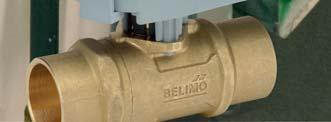
3 Overview Designed for maximum efficiency in tight spaces, Belimo s ZoneTight valve offering sets new design and performance standards for both pressure dependent and pressure independent zoning applications. ZoneTight Zone Valve (QCV) The ultra-compact QCV leads the way in Belimo s new generation of room and zone solutions. Equipped with a space-saving -way or 3-way ball valve and an electronic rotary actuator, the QCV has an installation height of just 4.33 inches (110 mm), available NPT or Sweat, and offers a number of benefits over conventional pressure dependent control valves, including: Belimo ball valve design with zero leakage eliminates energy loss. Self-cleaning ball valve technology provides superior clog resistance. Low power consumption up to 95% less than conventional zone valves. Field adjustable Cv value to meet your design requirements. ZoneTight Pressure Independent Zone Valve (PIQCV) The PIQCV offers all the advantages of a Pressure Independent Characterized Control Valve (PICCV) but in an ultra compact confi guration. The PIQCV combines a differential pressure regulator with a -way control valve to supply a specific fl ow for each degree of ball opening regardless of system pressure fluctuations. The valve performs the function of a balancing valve and control valve in one unit. Smallest pressure independent characterized ball valve in the market. ctuator runs at 0.3 W saving energy and transformer power. Flow is adjustable at the actuator and always perfectly balanced. Permits PIV installation in tight spaces. Pressure Flow PIQCV ZoneTight Zone Valve Valve body Control valve (QCV) ZoneTight Pressure Independent Zone Valve Valve body Control valve (PIQCV) Regulator 1 Body NPT or Sweat 3 Stem Ball with profi le 1 Body End Cap 4 5 Stem Ball with profi le 7 8 Regulator Cap Regulator Body 4 Seat 3 PT Ports 6 Seat 9 Diaphragm 10 Regulator Shaft 11 Regulator Spring 3

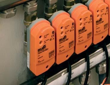
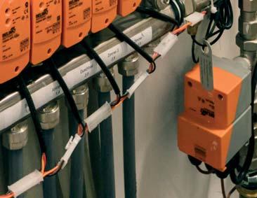
4 Features ZoneTight Features Compact Design When faced with limited available mounting space, the Belimo ZoneTight valve s super-compact design helps maximize workable space and complements OEM valve compartment optimization. Ball Valve Technology Unlike short stroke globe valves with plug and seat design, the self-cleaning ball helps minimize energy losses caused by clogging (0% to B leakage) and eliminates seat leakage. The intuitive confi guration also allows for bi-directional fl ow (QCV) unlike traditional paddle style zone valves. In addition, equal percentage fl ow characteristic provides superior part load coil performance. ctuator with Patented Brushless DC Motor The brushless DC motor s power consumption when running is a mere 0.3W, 0.15W when holding, saving energy and transformer power. In addition to signifi cantly reducing energy costs, this helps eliminate failures due to stalled motors and prolongs actuator life. It also allows for more units to be powered by a single transformer. Snap Fit The QCV and PIQCV easily connects to the actuator allowing operators and technicians to install valves quickly, easily, and without the use of tools. This helps simplify commissioning and reduces labor costs. Field djustable Max Cv/Flow QCVs and PIQCVs can be quickly and easily fi eld adjusted to ensure that necessary design requirements are met and reduces inventory. Stem Extension for Insulation Unlike conventional zone valve actuators, which are normally covered by pipe insulation, the stem extension on QCVs and PIQCVs allows for easy actuator removal without damaging the surrounding insulation, helping simplify operation and maintenance activities. 4
5 Nomenclature QCV Nomenclature Z 050 Q S -J +CQB 4 -SR -L Valve Type Z = -way Z3 = 3-way ZoneTight Chrome Plated Brass Ball and Brass Stem Valve Size 050 = ½ 075 = ¾ Quick Connect Connection Type Blank = NPT S = Sweat Cv -way F = 1.4 J = 5.9 K = way* E = 1 H =.7 J = 4.6 *On/off only. ctuator Type Non-Spring Return CQB CQKB Power Supply 4 = 4 VC/DC UP = VC Control -3 = On/Off, Floating Point -SR = Modulating Input = -10 VDC Direction of Rotation -L = Open ( VDC) -R = Close ( VDC) -LL = Normally Open, Fail Open -RR = Normally Close, Fail Close -LR = Normally Open, Fail Close -RL = Normally Close, Fail Open -S = Built-in ux. Switch Ordering Example 1 Choose the valve actuator combination. Z050QS-J+CQB4-SR Choose set-up required Modulating Non-Spring Models L = Normally Open R = Normally Closed Models LL = Normally Open/Fail Open LR = Normally Open/Fail Closed RL = Normally Closed/Fail Open RR = Normally Closed/Fail Closed Refers to valve ports from inlet to outlet, per fl ow arrow. Set-Up -L Tagging (if needed) 3 Does order require tagging? Tagging: Valves may be tagged per customer specifi cation. ($10.00 charge per tag) Example: HU-1 FCU- Part number for tagging: Complete Ordering Example: Z050QS-J+CQB4-SR-L 5
![QCV Product Range Valve Nominal Size Type Suitable ctuators C v Inches DN [mm] -way 3-way Non- Spring Return 1.4* ½ 15 Z050Q-F 5.9* ½ 15 Z050Q-J NPT 9.8* ¾ 0 Z075Q-K 1 ½ 15 Z3050Q-E Sweat.](/docs-images/80/81127654/images/6-0.jpg "7 ½ 15 Z3050Q-H 4.6 ¾ 0 Z3075Q-J 1.4* ½ 15 Z050QS-F 5.9* ½ 15 Z050QS-J 9.8* ¾ 0 Z075QS-K 1 ½ 15 Z3050QS-E.")
6 QCV Product Range Valve Nominal Size Type Suitable ctuators C v Inches DN [mm] -way 3-way Non- Spring Return 1.4* ½ 15 Z050Q-F 5.9* ½ 15 Z050Q-J NPT 9.8* ¾ 0 Z075Q-K 1 ½ 15 Z3050Q-E Sweat.7 ½ 15 Z3050Q-H 4.6 ¾ 0 Z3075Q-J 1.4* ½ 15 Z050QS-F 5.9* ½ 15 Z050QS-J 9.8* ¾ 0 Z075QS-K 1 ½ 15 Z3050QS-E.7 ½ 15 Z3050QS-H CQ Series CQK Series QCV Mode of Operation The ZoneTight Zone Valve (QCV) is operated by a rotary actuator. The actuators are controlled by a standard voltage for on/off control, a modulating signal, or 3-point control system which moves the ball of the valve to the position dictated by the control system. 4.6 ¾ 0 Z3075QS-J *Maximum fl ow. Max value can be field adjusted, see actuator instructions. Product Features The equal percentage characteristic of the flow is ensured by the design of the ball. This characteristic provides linear heating or cooling output from the coil improving energy efficiency and comfort. V max End Stop Positions V nom N No end stop Z050Q(S)-F (½ ) 0.1 N/ 0. N/ N/ 0.4 N/ Z050Q(S)-J (½ ) N/ N/.4 N/ Z075Q(S)-K (¾ ) N/ N/ 3.3 N/ ctuator Specifications Control type -3 on/off, fl oating point -SR modulating, -10 VDC Manual override use actuator to turn valve stem Electrical connection 3 ft. [1 m] cable with ½ conduit fitting screw terminals Power consumption CQ W running, 1.5 W holding CQK.. 3 W running, 1 W holding CQ..UP 1.5 W running, 1.1 W holding Power supply 4 VC/DC ( VC, UP) Transformer sizing CQ V CQK.. 8 V CQ..UP V Valve Specifications Service Flow characteristic Controllable flow range chilled or hot water, 60% glycol equal percentage (-way) linear (3-way) 75 (-way), 90 (3-way) Sizes ½, ¾ End fi tting NPT female sweat Materials Body forged brass Ball chrome plated brass Stem brass Seats Tefl on PTFE O-rings EPDM (lubricated) Media temp. range 36 F to 1 F [ C to 100 C] Media temp. limit 50 F [10 C] Maximum allowable operating temperature 1 F [100 C] Body pressure rating 360 psi Close-off pressure 75 psi Maximum differential pressure ( P) 40 psi Leakage 0% Tefl on is a registered trademark of DuPont If temperature exceeds 1 F [100 C] operating range due to a boiler control failure the valve will safely contain the hot water but manufacturer s product warranty becomes invalid. 6
7 Nomenclature PIQCV Nomenclature Z 050 Q P T -B +CQB 4 -SR -R Valve Type Z = -way ZoneTight Chrome Plated Brass Ball and Brass Stem Valve Size 050 = ½ 075 = ¾ Quick Connect Pressure Independent T = PT Port Flow Rate B = 0.9 GPM D =.0 GPM F = 4.3 GPM G = 9.0 GPM ctuator Type Non-Spring Return CQB CQKB Power Supply 4 = 4 VC/DC UP = VC Control -3 = Floating Point -SR = Modulating Input = -10 VDC Direction of Rotation -L = Open ( VDC) -R = Close ( VDC) -LL = Normally Open, Fail Open -S = Built -in ux. Switch -RR = Normally Close, Fail Close -LR = Normally Open, Fail Close -RL = Normally Close, Fail Open Ordering Example 1 Choose the valve actuator combination. Z050QPT-B+CQB4-SR Choose set-up required. Modulating Non-Spring Models L = Normally Open R = Normally Closed Models LL = Normally Open/Fail Open LR = Normally Open/Fail Closed RL = Normally Closed/Fail Open RR = Normally Closed/Fail Closed Set-Up -R Re fers to valve ports from inlet to outlet, per fl ow arrow. Tagging (if needed) 3 Does order require tagging? Tagging: Valves may be tagged per customer specifi cation. ($10.00 charge per tag) Example: HU-1 FCU- Part number for tagging: Complete Ordering Example: Z050QPT-B+CQB4-SR-R 7
![PIQCV Product Range Valve Nominal Size Type Suitable ctuators GPM Inches DN [mm] -way NPT with PT ports 0.9* ½ 15 Z050QPT-B.0* ½ 15 Z050QPT-D 4.3* ½ 15 Z050QPT-F 9.](/docs-images/80/81127654/images/8-0.jpg "0* ¾ 0 Z075QPT-G Non-Spring Return CQ Series *Maximum fl ow. Max value can be field adjusted, see actuator instructions.")
8 PIQCV Product Range Valve Nominal Size Type Suitable ctuators GPM Inches DN [mm] -way NPT with PT ports 0.9* ½ 15 Z050QPT-B.0* ½ 15 Z050QPT-D 4.3* ½ 15 Z050QPT-F 9.0* ¾ 0 Z075QPT-G Non-Spring Return CQ Series *Maximum fl ow. Max value can be field adjusted, see actuator instructions. CQK Series PIQCV Clip Position for Flow djustment (GPM) N No Clip Z050QPT-B N/ N/ N/ N/ 0.4 N/ Z050QPT-D Z050QPT-F N/ Z075QPT-G N/ ctuator Runtime 30 sec. 37 sec. 43 sec. 49 sec. 55 sec. 6 sec. 68 sec. 75 sec. For additional intermediate settings see technical documentation or the ZoneTight fl ow capacity setting tool on or Mode of Operation The ZoneTight Pressure Independent Zone Valve (PIQCV) is a two-way valve which combines the functionality of a control valve and a pressure regulating valve, creating one precise product which is unaffected by pressure variations in a system. Product Features Constant flow regardless of pressure variations in the system at set degrees of ball opening. Maximizes chiller ΔT, preventing energizing additional chillers due to low ΔT. Simplifi ed valve sizing and selection, no C v calculations required. ctuator Specifications Control type -3 on/off, floating point -SR modulating, -10 VDC Manual override use actuator to turn valve stem Electrical connection 3 ft. [1 m] cable with ½ conduit fitting screw terminals Power consumption CQ W running, 0. W holding CQK...5 W running, 0.5 W holding CQ..UP 1 W running, 0.7 W holding Power supply 4V ( VC, UP) Transformer sizing CQ V CQK.. 5 V CQ..UP V Valve Specifications Service chilled or hot water, 60% glycol Flow characteristic equal percentage Controllable flow range 75 Sizes ½, ¾ End fitting NPT female Materials Body forged brass Ball stainless steel Stem stainless steel Seats Tefl on PTFE O-rings PTFE Spring stainless steel Media temp. range 36 F to 1 F [ C to 100 C] Media temp. limit 50 F [10 C] Maximum allowable operating temperature 1 F [100 C] PT ports Body pressure rating 360 psi Close-off pressure 00 psi Differential pressure (ΔP) range 5 to 50 psi Leakage 0% If temperature exceeds 1 F [100 C] operating range due to a boiler control failure the valve will safely contain the hot water but manufacturers product warranty becomes invalid. 8
9 Set-Up QCV ND PIQCV SET-UP- Specify Upon Ordering -WY VLVE 3-WY VLVE (QCV ONLY) NON-SPRING RETURN Stays in Last Position CQBUP-3 CQB4-3 CQB4-SR Power to brown wire (pin for -T versions) will drive valve CW. Power to blue wire (pin 3 for -T versions) will drive valve CCW. Power to red wire (pin for -T versions) will drive valve CW. Power to white wire (pin 3 for -T versions) will drive valve CCW. CQB4-SR-R: Normally closed, valve will open as voltage increases CQB4-SR-L: Normally open, valve will close as voltage increases Power to brown wire (pin for -T versions) will drive valve CW. Power to blue wire (pin 3 for -T versions) will drive valve CCW. Power to red wire (pin for -T versions) will drive valve CW. Power to white wire (pin 3 for -T versions) will drive valve CCW. CQKB4 CQKB4-S CQKB4-LL, CQKB4-S- LL: Normally open CCW, valve will drive closed when energized. ction: ctuator will fail open CCW upon power loss. CQKB4-RR, CQKB4-S- RR: Normally closed CW, valve will drive open when energized. ction: ctuator will fail closed CW upon power loss. One wire control for CW or CCW rotation. FIL-SFE CQKB4-SR CQKB4-SR-RL: Normally closed CW, valve will open as voltage increases. ction: Will fail open upon power loss. CQKB4-SR-LL: Normally open CCW, valve will close as voltage increases. ction: Will fail open upon power loss. CQKB4-SR-RR: Normally closed CW, valve will open as voltage increases. ction: Will fail closed upon power loss. CQKB4-SR-LR: Normally open CCW, valve will close as voltage increases. ction: Will fail closed upon power loss. 9

![Designed for chilled water service up to 104 F [40 C] media temperature PIQCV QCV FLOW ORIFICE FO15010 ½ Flow orifice for](/docs-images/80/81127654/images/10-1.jpg "1.0 GPM FO1505 ½ Flow orifice for.5 GPM FO15055 ½ Flow orifice for 5.5 GPM FO0100 ¾ Flow orifice for 10.")
10 ccessories VLVE TYPE ZONETIGHT VLVE CCESSORIES Valves Z (-WY) Z3 (3-WY) ZCQB-FL Flow setter PIQCV QCV ZCQ-E QCV or PIQCV valve stem extension. Designed for chilled water service up to 104 F [40 C] media temperature PIQCV QCV FLOW ORIFICE FO15010 ½ Flow orifice for 1.0 GPM FO1505 ½ Flow orifice for.5 GPM FO15055 ½ Flow orifice for 5.5 GPM FO0100 ¾ Flow orifice for 10.0 GPM PIQCV QCV PIQCV QCV PIQCV QCV QCV RCHITECTURL COVER ZCQB-W Housing cover for CQ actuators (white) PIQCV QCV 10

11 Flow Pattern QCV Flow Pattern QCV -way valves can be piped with fl ow entering and exiting either port. For on/off control of coil fl ow the QCV 3-way valve is piped with supply entering the bottom part. For a QCV 3-way switching application, pipe hot and cold supply water to either side ports and the appropriate seasonal supply water will exit the bottom port for regulation by another -way valve; typically installed in the return pipe. INLET OUTLET Side Side Bottom PIQCV Flow Pattern The PIQCV consists of a differential pressure regulator and a control valve. The control valve is throttled to match the fl ow command of the control signal. The differential pressure regulator holds the pressure drop across the ball of the valve. s system pressure changes, the differential pressure regulator moves in response to keep the fl ow stable. Pressure (P1) at the inlet PIQCV is high and pressure (P3) at the outlet is low. The differential pressure between (P1) and (P3) must be between 5-50 to achieve pressure independent fl ow. When differential pressure increases the regulator opening is decreased. When differential pressure decreases the regulator opening is increased. This allows for the constant pressure differential across the ball of the valve. P3 P3 P P1 11
12 Piping QCV Typical Piping -way Valve Piping Diagram 3-way Switching Valve Piping Diagram 3-way Diverting Valve Piping Diagram PIQCV Typical Piping PIQCVs are recommended to be installed on the return side of the coil. This diagram represents a typical application. Consult engineering specifi cation and drawings for project details. PT ports are recommended if not supplied on either side of the valve and the supply side of the heat transfer device to allow for pressure/fl ow measurement/calculation. H/C COIL FLOW IR VENT DRIN BELIMO PIQCV (TYP.) FLOW P/T PORT UNION CONNECTION (TYP.) P/T PORT FLOW P/T PORT STRINER (Optional) FLOW FLOW SHUT OFF VLVE SHUT OFF VLVE 1
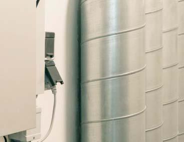
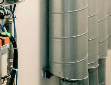
13 Belimo ZoneTight Zone Valves Orientation QCV/PIQCV Orientation QCV and PIQCV assemblies can be installed in a vertical or horizontal arrangement, as long as the actuator is positioned to avoid water from dripping on the actuator.! QCV kg PIQCV kg >1 F PIQCV s should be installed with flow in the direction of the arrow on the valve body. If installed backwards, there could be damage to either the diaphragm or the regulator. The valve assembly can be installed in a vertical or horizontal arrangement US CND LTIN MERIC / CRIBBEN 13
14 Belimo ZoneTight Zone Valves Field-Set djustment QCV/PIQCV Field-Set Flow Capacity djustment lign the clip to the notch scale found on the underside of the actuator to the corresponding flow in the table below. For 3-point floating control signals adjust the controller runtime parameter to match the runtime of the of the final clip position. For analog -10 VDC control signals see adaption instructions. For incremental notch settings refer to the flow graphs on page 5 or visit and put in your flow requirements to determine your notch position. QCV 1 1 V'max End Stop Positions Size Valve Model 1/" Z050Q(S)-F 0.1 1/" Z050Q(S)-J /4" Z075Q(S)-K Runtime (seconds) N No end stop PIQCV Valve Model 1/" Clip Position for Flow djustment (GPM) Z050QPT-B Z050QPT-D Z050QPT-F N- N No Clip Valve Model 3/4" Z075QPT-G Runtime NPT Installation ZoneTight valves are provided with SME NPT female pipe treads for connection to threaded pipe US CND LTIN MERIC / CRIBBEN 1 V'nom
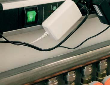
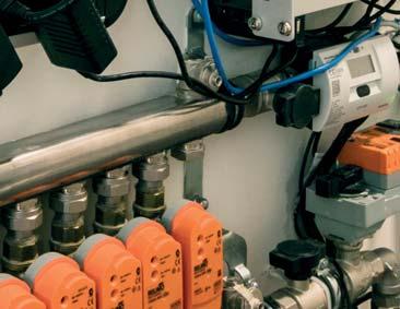
15 Belimo ZoneTight Zone Valves Installation ctuator ttachment for QCV/PIQCV ttach the actuator to the valve body. lign the actuator guide pins to the valve bonnet openings and press down until a click is heard. To remove the actuator, grasp it with your hand and pull it away from the valve body. click 3 1 daption for Proportional ctuators For actuators with analog -10 VDC signal, after flow capacity adjustment has been field-set by moving the clip to a desired position, execute the adaption routine to scale the signal across the available travel. The actuator will travel first in one direction and stall, then will travel in the opposite direction and stall. Then it will travel to the commanded position of the control signal. When the actuator is powered for the first time the adaption routine will execute automatically. Execute the adaption function any time the clip position is changed. The adaption routine does not change the actuator speed, which is 75 seconds over 90 degree rotation. daption For actuators with On/Off or Floating Control input there is no adaption function or button. Proportional ctuators: CQB4-SR, CQB4-SR-L, CQB4-SR-R, CQKB4-SR, CQKB4-SR-LL, CQKB4-SR-RR, CQKB4-SR-LR, CQKB4-SR-RL On/Off, Floating Point ctuators: CQB4-3, CQBUP-3 On/Off ctuators: CQKB4, CQKB4-S Proportional ctuator Insulation On/Off, Floating Point ctuator Insulation should wrap the pipe and valve body but not the actuator. For chilled water applications use the stem extension kit accessory to raise the actuator above the valve body to provide space for insulation. kg >1 F US CND LTIN MERIC / CRIBBEN 15
16 Wiring Diagrams Wiring Diagrams Provide overload protection and disconnect as required. Line Volts Blk Red Common + Hot ctuators may be connected in parallel. Power consumption and input impedance must be observed. 3 ctuators may also be powered by 4 VDC. 5 Only connect common to neg. (-) leg of control circuits (ZG-R01) converts the 4 to 0 m control signal to to 10 VDC. Functions 0% 100% Fail Position 100% Open S1 S ctuators with plenum rated cable do not have numbers on wires; use color codes instead. On/Off, CQKB4-S-LL NO 100 One built-in auxiliary switch (1x SPST), for end position indication, interlock control, fan startup, etc Line Volts Blk Red Common + Hot Meets culus requirements without the need of an electrical ground connection WRNING Live Electrical Components! During installation, testing, servicing and troubleshooting of this product, it may be necessary to work with live electrical components. Have a qualified licensed electrician or other individual who has been properly trained in handling live electrical components perform these tasks. Failure to follow all electrical safety precautions when exposed to live electrical components could result in death or serious injury. Control Signal VDC/m 500 VDC Close Open 10 VDC Open Close Fail Position Wht 100% Open Y 1 Input, to 10V Line Volts 3 18 Blk Common Red Hot + Line Volts Control Signal VDC/m 500 Blk Red Wht Common + Hot Y 1 Input, to 10V On/Off, CQKB4-RR Line Volts On/Off, CQKB4-LL Line Volts Functions 0% 100% Fail Position Functions 0% 100% Fail Position 100% Open 3 18 Blk Common Red Hot + 0% Close 3 18 Blk Common Red + Hot VDC Open 10 VDC Close Fail Position 0% Close Proportional, CQKB4-SR-LR Line Volts Control Signal VDC/m 500 VDC Close Close 10 VDC Open Open Fail Position Proportional, CQKB4-SR-RL Line Volts Blk Red Wht 100% Open Common + Hot Y 1 Input, to 10V Blk Red Common + Hot Control Signal VDC/m 500 Wht Y 1 Input, to 10V Functions 100% VDC Close Close 0% 10 VDC Open Open Fail Position 0% Close S1 Fail Position 0% Close S On/Off, CQKB4-S-RR NO Proportional, CQKB4-SR-RR 16
17 Wiring Diagrams Wiring Diagrams ctuators may be connected in parallel. Power consumption and input impedance must be observed. 3 ctuators may also be powered by 4 VDC. Line Volts Blk Red Common + Hot 5 Only connect common to neg. (-) leg of control circuits (ZG-R01) converts the 4 to 0 m control signal to to 10 VDC. Control Signal VDC/m 500 Wht Y 1 Input, to 10V 18 ctuators with plenum rated cable do not have numbers on wires; use color codes instead. VDC Open 10 VDC Close Meets culus requirements without the need of an electrical ground connection WRNING Live Electrical Components! During installation, testing, servicing and troubleshooting of this product, it may be necessary to work with live electrical components. Have a qualified licensed electrician or other individual who has been properly trained in handling live electrical components perform these tasks. Failure to follow all electrical safety precautions when exposed to live electrical components could result in death or serious injury. Proportional, CQB4-SR-L Line Volts 4 VC Transformer Control Signal VDC/m Blk Red Wht Common + Hot Y 1 Input, to 10V VDC Close 10 VDC Open 4 VC Transformer 3 18 Proportional, CQB4-SR-R Line Volts Blk Common Red + Wht + Line Volts 110 to 30 VC 18 Blu Common Brn + Wht + On/Off, CQB4-3 Line Volts Functions 100% 0% Functions 0% 100% B B Common On/Off, CQBUP-3 Line Volts Functions 0% 100% Functions 100% 0% B B 18 Blu Common Brn + Wht + Floating Point, CQB4-3 Floating Point, CQBUP-3 17
18 Flow Verfication PIQCV Flow Verification and Commissioning Overview without Flow Orifice Device fter the actuator travel limit clip has been correctly located to position 1-7 (or removed) to match the maximum flow setting of the coil, the following procedures detail the flow verification and commissioning procedures for Pressure Independent Valves Quick Compact Valves (PIQCV). These procedures are not mandatory to ensure proper operation of PIQCV. PIQCVs are very different from pressure dependent control valves (standard control valves). Pressure variations in the system do not affect flow through the PIQCV. dditional flow regulating devices (e.g. circuit setters and automatic flow limiting devices) should not be used in conjunction with PIQCVs. This makes the Testing and Balancing (TB) or commissioning process much different from standard control valves. PIQCVs offer numerous maximum design flow values in each valve body size. It is important to note that the valve will travel to 90 degrees only when there is no end stop. External P/T ports allow for independent verifi cation of proper PIQCV operation. dditionally, these ports allow for future comprehensive troubleshooting and diagnosis. For proper and accurate fl ow verifi cation of the mechanical PIQCV, it is essential that the mechanical contractor install P/T ports, B & C as shown in Figure if the mechanical PIQCV body is not supplied with integrated ports. If the PIQCV includes integrated PT ports the mechanical contractor only needs to install P/T port. Mechanical PIQCV Pre-Flow Verification Checklist Verify that system is purged of air and fi lled to proper pressure. Verify that each PIQCV has the manufacturer s required operating differential pressure range across P/T ports B and C (or P1 and P3) as shown in fi g.. Verify proper pump operation per manufacturer s specifi cations. Verify proper supply water temperature is available and is at design temperature. Proper air fi lter maintenance has been completed. Fan belts are in proper working order. Heat transfer devices (coils) are clean. Strainers are clean. ll manual shutoff valves are open. ll bypass valves are closed. No automatic or manual balancing valves exist. If they do exist, they must be set fully open and locked to not interfere with the pressure independency function of the PIQCV. P/T port and P/T port B (or and P1) are used for measuring pressure differential across the coil (used to measure water P to equate to fl ow) or to measure water T across the coil. P/T port B and P/T port C (or P1 and P3) are used to measure P across the PIQCV assembly. PIQCVs must have 5 50 psid (11.5 ft. 115 ft. HO) (or per manufacturer s specifi cation) differential pressure within this range. Do not manually remove the actuator travel limit clip to fully open the valve to check for design fl ow or pressure. Valve shall be commanded to design fl ow position via analog or BMS (Building Management System) signal. The required operating differential pressure range is necessary to insure pressure independent operation of the PIQCV Note: The fl ow setter (ZCQB-FL) can be used to adjust the fl ow if the BMS is not available during the commissioning process. H/C COIL IR VENT FLOW BELIMO PIQCV (TYP.) P/T PORT B P1 P3 P/T PORT C FLOW SHUT OFF VLVE UNION CONNECTION (TYP.) FLOW DRIN P/T PORT FLOW STRINER (Optional) FLOW SHUT OFF VLVE 18
19 Flow Verification Procedures without Flow Orifice Device Procedure #1 (System Verifi cation) Total System Flow Method Verifi cation for PIQCV Cooling/Heating 1. Verify that the system is in proper working order. Depending on the valves used, check the items listed for PIQCV Pre-Flow Verification Checklists.. If diversity factor = 100%, command open all PIQCV s via the BMS system. Systems with less than 100% diversity need to have a number of valves closed to match design diversity. 3. Ensure that pumps are either manually commanded to suffi cient speed to provide proper differential pressure across all valves OR if pumps are under DDC pressure control ensure P setpoint is suffi cient to provide the above conditions. Verify total system fl ow in main return line is at system design fl ow rate using one of the following methods: Orifi ce, Venturi, Electronic fl ow meter, System-level Flow Device 1. Decrease the pump speed (or decrease P setpoint if under control) until a measureable fl ow decrease occurs.. Increase pump speed (or increase P setpoint if under control) slowly until design fl ow is reestablished. Make note of the resulting P. This will be the maximum system P operating setpoint. Note: If total fl ow does not match design fl ow then troubleshooting must be done to determine cause. This may involve verifying fl ows at the terminal level. Procedure # (Terminal Level Verifi cation) ir Delta T Method Verifi cation for PIQCV Cooling/Heating 1. Verify that the system is in proper working order. Depending on the valves used, check the items listed for PIQCV Pre-Flow Verification Checklists.. Ensure that water is at design temperature. 3. Ensure that terminal airfl ow is at design airfl ow rate (cfm). 4. Command open the PIQCV via analog or BMS control signal to maximum design fl ow position. (Do not manually open the PIQCV beyond the actuator travel limit clip position). 5. Reference approved engineering document containing design air temperature drop/rise for design conditions. 6. Measure coil inlet air temperature and coil discharge air temperature. 7. Difference between coil inlet air reading (ET) and coil discharge air reading (LT) should equal to or exceed design air delta T as shown on the contract documents. Procedure #3 (Terminal Level Verifi cation) Water Delta Method Verifi cation for PIQCV Cooling/Heating 1. Verify that the system is in proper working order. Depending on the valves used, check the items listed for PIQCV Pre-Flow Verification Checklists. Ensure that water is at design temperature.. Ensure that terminal airfl ow is at design fl ow rate (cfm) or water coil airfl ow is unencumbered. 3. Command open the PIQCV via analog or BMS control signal to maximum design fl ow position. (Do not manually open the PIQCV beyond the actuator travel limit clip position.) 4. Reference approved engineering document containing design water temperature drop/rise for design conditions. 5. Measure water temperature differential of coil by using P/T ports and B (or and P1) as referenced in Fig.. 6. Measured temperature differential should be equal to designed water temperature differential (EWT, LWT) as shown on the contract documents. Procedure #4 (Terminal Level Verifi cation) Coil P (Delta P) Method Verifi cation for PIQCV Cooling/Heating 1. Verify that the system is in proper working order. Depending on the valves used, check the items listed for PIQCV Pre-Flow Verification Checklists.. Command open the PIQCV via analog or BMS control signal to maximum design fl ow position. (Do not manually open the PIQCV beyond the actuator travel limit clip position.) 3. Ensure P across valve assembly between P/T ports B and C (or P1 and P3) as shown above in Fig. is within manufacturer s operating parameters. 4. Reference approved engineering document containing design coil water pressure drop (usually expressed in ft. of water) for design fl ow conditions. This value will be for the heating/cooling coil associated with corresponding PIQCV. 5. Measure coil P by using P/T ports and B (or and P1) as referenced in Fig.. 6. Formula to calculate fl ow is: ctual GPM = Design GPM x (Measured Coil P/Design Coil P) Note: Measured Coil P and Design Coil P must be expressed in the same engineering units (feet of water, inches of water, psi, etc.). 19
20 1 Belimo ZoneTight Zone Valves Flow Verfication Flow Verification with Flow Orifice Device Belimo fl ow orifi ce device has two pressure ports for fi eld P measurement with a manometer gauge. Connect manometer high pressure line to fl ow orifi ce red PT port; connect low pressure line to green PT port. Follow gauge instructions to verify connections. Take P reading in inches of water (w.c.) and transpose to the Flow Orifi ce line of the Flow Chart. From that point follow the corresponding chart line to the fl ow scale and determine the actual fl ow. Refer to fi eld-set procedure section on page 14 to adjust fl ow capacity to meet project requirements. Meter Readings, 70 F / 1 C FO15010 FO1505 FO15055 FO0100 FO15010 FO1505 FO15055 FO0100 FO15010 FO1505 FO15055 FO0100 Temperature Correction Factor: 155 F / 68 C = 1.01 x GPM 05 F / 96 C = 1.0 x GPM How to Determine Flow: 1. Enter the chart with the P (differential pressure) reading.. Go horizontally across to the size of the valve. 3. Go vertically up or down to read the GPM (flow). 0
21 Troubleshooting Problem Field Observations Possible Solution ctuator will not move. ctuators wires are connected. Verify the power supply and control signal are wired and operating correctly. ctuator does not modulate with the control signal as expected. Valve is yielding fl ow but cannot be commanded to the full fl ow setting Full fl ow is lower than expected. Desired fl ow cannot be reached. Flow measurements are not stable. Valve throttles to a different position than expected. Valve is partially open but will not move to a full open position with a full signal command. Clip may be in the wrong position. Valve is wide open. ir may be in the system. Remove the actuator from the valve body and use the actuator or a slotted screwdriver to move the valve stem to verify free rotation. For 3-point fl oating signals the actuator runtime is relative to the travel set by the clip. The controller runtime parameter may need to be adjusted to match the runtime of the actuator. For analog actuators the adaption function may have previously occurred to a lesser angle of rotation than now exits. Press the adaption button and the actuator will re-scale to the full travel set by the clip position. The clip may need to be adjusted to a greater angle of rotation to allow more fl ow, or removed to obtain maximum fl ow capacity. Refer to the fl ow commissioning instructions (page 18) for adjustment and verifi cation procedures. Increase the pump differential pressure to resolve low fl ow problems. Remove air from the system to solve the problem. 1

, linear (3-way) Controllable fl ow range 75 (-way), 90 (3-way) Size ½, ¾")
22 Chrome Plated Brass Ball, NPT Female Ends pplication The QCV zone valves are suited for large commercial buildings where higher close-off and the ability to change fl ow is desired. Common applications include unit ventilators, fan coil units, VV reheat coils, fi n tube casing, radiant panels and duct coils. The valve fi ts in space restricted areas and can be assembled without the use of tools. Dimensions -Way QCV Valve Specifications Service chilled or hot water, 60% glycol Flow characteristic equal percentage (-way), linear (3-way) Controllable fl ow range 75 (-way), 90 (3-way) Size ½, ¾ Type of end fi tting NPT female ends Materials Body forged brass Ball chrome plated brass Stem brass Seats Tefl on PTFE O-rings EPDM (lubricated) Media temperature range 1 F to 1 F [-6 C to 100 C] Media temperature limit* 50 F [10 C] Max. allowable operating temp. 1 F [100 C] Body pressure rating 360 psi Close-off pressure 75 psi Maximum differential pressure ( P) 40 psi Leakage 0% *If temperature exceeds 1 F [100 C] operating range due to a boiler control failure the valve will safely contain the hot water but manufacturers product warranty becomes invalid. E Valve Nominal Size DN In. [mm] ½ Non-Spring 15 Return ¾ Non-Spring 0 Return ½ 15 ¾ Dimensions 3-Way Valve Nominal Size DN In. [mm] ½ Non-Spring 15 Return ¾ Non-Spring 0 Return ½ 15 E 0 F F D B Dimensions (Inches [mm]) B C D E F 4.5 [114] 4.5 [114] 4.5 [114] D.05 [5].4 [61].05 [5] B Dimensions (Inches [mm]) B C D E F 4.5 [114] 4.5 [114] 4.5 [114] 4.5 [114].05 [5].4 [61].05 [5].4 [61] 3.7 [83] 3.4 [86.9] 3.7 [83] 3.4 [86.9] 3.83 [97] 3.98 [101] 3.83 [97].71 [69].77 [70].71 [69].77 [70].71 [69].77 [70].71 [69] 1.88 [48] 0.94 [4] 0.94 [4] 1.88 [48] 1.0 [6] 1. [31] 1.0 [6] 1.88 [48] 0.94 [4] 0.94 [4] 1.88 [48] C 1.0 [6] 1. [31] 1.0 [6] C ¾ [114].4 [61] 3.98 [101].77 [70] 1. [31] 1. [31]

23 Chrome Plated Brass Ball, Sweat Connection pplication The QCV zone valves are suited for large commercial buildings where higher close-off and the ability to change fl ow is desired. Common applications include unit ventilators, fan coil units, VV reheat coils, fi n tube casing, radiant panels and duct coils. The valve fi ts in space restricted areas and can be assembled without the use of tools. Dimensions -Way QCV Valve Specifications Service chilled or hot water, 60% glycol Flow characteristic equal percentage (-way), linear (3-way) Controllable fl ow range 75 (-way), 90 (3-way) Size ½, ¾ Type of end fi tting sweat Materials Body forged brass Ball chrome plated brass Stem brass Seats Tefl on PTFE O-rings EPDM (lubricated) Media temperature range 36 F to 1 F [ C to 100 C] Media temperature limit* 50 F [10 C] Max. allowable operating temp. 1 F [100 C] Body pressure rating 360 psi Close-off pressure 75 psi Maximum differential pressure ( P) 40 psi Leakage 0% *If temperature exceeds 1 F [100 C] operating range due to a boiler control failure the valve will safely contain the hot water but manufacturers product warranty becomes invalid. E Valve Nominal Size DN In. [mm] ½ Non-Spring 15 Return ¾ Non-Spring 0 Return ½ 15 ¾ Dimensions 3-Way Valve Nominal Size DN In. [mm] ½ Non-Spring 15 Return ¾ Non-Spring 0 Return ½ 15 E 0 F F D B Dimensions (Inches [mm]) B C D E F 4.78 [1] 4.95 [16] 4.78 [1] D.6 [67].95 [75].6 [67] B Dimensions (Inches [mm]) B C D E F 4.78 [1] 4.95 [16] 4.95 [16] 4.78 [114].6 [67].95 [75].95 [75].6 [67] 3.14 [80] 3.8 [84] 3.8 [84] 3.14 [80] 3.14 [80] 3.8 [84] 3.14 [80].56 [66].64 [68].64 [68].56 [66].56 [65].64 [68].56 [65] 1.0 [6] 1. [31] 1. [31] 1.0 [6] 1.0 [6] 1. [31] 1.0 [6] 1.0 [6] 1. [31] 1. [31] 1.0 [6] C 1.0 [6] 1. [31] 1.0 [6] C ¾ [16].95 [75] 3.8 [84].64 [68] 1. [31] 1. [31] 3
24 Belimo ZoneTight Pressure Independent Zone Valves Stainless Steel Ball, NPT Female Ends pplication The PIQCV zone valves with its pressure independent technology are suited for large commercial buildings where higher close-off and dynamic balancing is required. Common applications include unit ventilators, fan coil units, VV reheat coils, fin tube casing, radiant panels and duct coils. The valve fits in space restricted areas and can be assembled without the use of tools. PIQCV Dimensions Valve Specifications Service chilled or hot water, 60% glycol Flow characteristic equal percentage Controllable fl ow range 75 Size ½ Type of end fi tting NPT female ends Materials Body forged brass Ball stainless steel Stem stainless steel Stem packing EPDM (lubricated) Seats Tefl on PTFE O-rings PTFE Seat o-rings EPDM Spring stainless steel Media temperature range 36 F to 1 F [ C to 100 C] Media temperature limit* 50 F [10 C] Max. allowable operating temp. 1 F [100 C] PT ports included Body pressure rating 360 psi Close-off pressure 00 psi Differential pressure ( P) range 5 to 50 psi Leakage 0% *If temperature exceeds 1 F [100 C] operating range due to a boiler control failure the valve will safely contain the hot water but manufacturers product warranty becomes invalid. Valve Nominal Size DN In. [mm] ½ Non-Spring 15 Return ¾ Non-Spring 15 Return ½ ¾ E F D Dimensions (Inches [mm]) B C D E F 4.71 [10] 5.11 [130] 4.71 [10] 5.11 [130] 3.74 [95] 4.63 [118] 3.74 [95] 4.63 [118] 4.07 [104] 5.17 [13] 4.07 [104] 5.17 [13] B 3.31 [80] 3.65 [93] 3.31 [80] 3.65 [93].3 [57].55 [65].3 [57].55 [65] 1.03 [7] 1.5 [39] 1.03 [7] 1.5 [39] C 4
25 Non-Spring Return and ctuator Series Operation The ZoneTight Zone Valves (QCV, PIQCV) are operated by rotary actuators. The actuators are controlled by a standard voltage for on/off control, proportional signal, or 3-point control system which move the ball of the valve to the position dictated by the control system. Non-Spring Return CQ.., CQ..UP ctuators CQK.. ctuator Specifications Power supply 4V ( VC, UP series) Manual override use actuator or slotted screwdriver to turn valve stem Power consumption CQ W running, 0. W holding CQK....5 W running, 0.5 W holding CQ..UP 1.0 W running, 0.7 W holding Transformer sizing CQ V CQK... 5 V CQ..UP V Electrical connection 3 ft., 18 G, plenum rated cable ½ conduit connector Overload protection Non-Spring Return electronic throughout 0 to 90 rotation electronic throughout full stroke Operation range Y on/off ngle of Rotation 90, adjustable with mechanical stop Position Indication pointer Running Time (Motor) 75 seconds Running Time () 60 seconds Humidity 5 to 95% RH non-condensing mbient Temperature Range +35 F to +104 F [+1.7 C to +40 C] Storage Temperature Range -40 F to +176 F [-40 C TO +80 C] Housing NEM, IP40, UL enclosure type Housing Material UL94-5V culus acc. to UL /--14, CN/CS gency Listings E :0, CE acc. to 004/108/EC and 006/95/EC Noise Level (Motor) <35 db () Servicing maintenance free Quality Standard ISO 9001 Weight Non-Spring Return 0.44 lb [0. kg] 3.6 lbs [1.6 kg] Quality standard ISO 9001 gency listings UL /-14, -18, CE according to 004/108/EC and 006/95/EC 5
26 Flow Curves Valve Flow Charts Two notch positions exist between numbered notches for fi eld-set clip positioning to obtain maximum fl ow capacity. Refer to charts and set the clip as needed. QCV Flow Curves ctuator Runtime (Seconds) Cv N (Default) Clip in Notch Position Removed Z050Q-F Flow Capacity ctuator Runtime (Seconds) Cv N Removed (Default) Clip in Notch Position Z050Q-J Flow Capacity ctuator Runtime (Seconds) Cv N (Default) Clip in Notch Position Removed Z050Q-K Flow Capacity 6
27 Flow Curves PIQCV Flow Curves ctuator Runtime (Seconds) ctuator Runtime (Seconds) GPM GPM N (Default) Removed N (Default) Removed Clip in Notch Position Clip in Notch Position Z050QP(T)-B Flow Capacity Z050QP(T)-D Flow Capacity ctuator Runtime (Seconds) ctuator Runtime (Seconds) GPM GPM N Removed N Removed Clip in Notch Position Z050QP(T)-F Flow Capacity (Default) Clip in Notch Position Z050QP(T)-G Flow Capacity (Default) 7
28 Terms and Conditions of Sale and Warranty I. General 1.1. The following Terms and Conditions of Sale ( Terms ) apply to the sale of products described in this Product Guide ( Products ). s used herein, Seller or Belimo refers to Belimo ircontrols (US) Inc., or Belimo ircontrols (CN) Inc., Belimo ircontrols (L) Inc., or Belimo utomation G as applicable, and Client refers to the individual or business entity that purchases the Products from Seller. These Terms shall apply unless the parties mutually agree to different terms and memorialize such agreement in writing signed by both Client and Seller. In case Seller s delivery includes Software and accompanying documentation, the terms of the license agreement are applicable in addition to these Terms. However, in case of disputes arising out of the Software, the license agreement shall prevail. II. III. IV. Price.1. The Seller s price for Products (the Price ) is net, F.O.B. Point of Origin, and is calculated in US currency for sales made by Belimo ircontrols (US), Inc. and calculated in Canadian currency for sales made by Belimo ircontrols (CN) Inc., and Brazilian currency for sales made by Belimo utomation G to Clients in Brazil... The Price, unless otherwise agreed upon, does not include freight and packaging (wooden crates, pallets, etc), the costs of which will be charged to Client at cost for each shipment and shall be payable with payment of the Price..3. Orders for Products with a net value of less than US $300 (CN $300) will be subject to a US $0 (CN $0) handling fee (the Handling Fee ). The Handling Fee will not be charged for orders of Products with a net value equal to or greater than US $300 (CN $300) or for Products ordered through Seller s ecommerce ordering system at: Seller reserves the right to make partial deliveries of orders of Products, each of which deliveries may be invoiced separately by Seller..5. The Price does not include charges for wiring diagrams, installation, and commissioning, which will be charged to Client separately and will be payable on demand. Payment 3.1. Invoices are payable in US currency for sales made by Belimo ircontrols (US), Inc., in Canadian currency for sales made by Belimo ircontrols (CN) Inc. and in Brazilian currency for sales made by Belimo utomation G on behalf of Brazil. Invoices are due no later than 30 days from the date of invoice, without any deductions. 3.. If Client maintains an outstanding balance for 45 days or more after the date of invoice, Client may be subject to restricted shipments of Products. Client may also be required to pay for all future deliveries of Products on a cash-on-delivery or approved credit card only basis. Title and Risk 4.1. Title to all Products shall remain with Seller and shall not pass to Client until Seller has received full payment for the Products. V. Damage or Loss in Transit 5.1. Seller assumes no liability for damage or loss of shipment of Products, which risk shall at all times remain with the carrier. ll shipments must be unpacked and examined by Client immediately upon receipt. ny external evidence of loss or damage must be noted on the freight bill accompanying the shipment of Products or carrier s receipt and signed by the carrier s agent at the time of delivery. Failure to do so will result in the carrier s refusal to honor any claim relating to damage of Products. Client must also notify Seller within 5 days of such damage by providing Seller with a copy of the freight bill or damage report so that Seller can file a claim for loss or damage in transit with the carrier. If the damage does not become apparent until the shipment is unpacked, Client must make a request for inspection by the carrier s agent and file with the carrier within 15 days after receipt of product and notify Seller of the same. VI. Delivery 6.1. Seller undertakes to make every attempt to adhere to its stated delivery parameters and to make a timely delivery of the Products but does not guarantee any delivery specifications. Each contract entered into for the purchase of Products is not cancelable nor is Seller liable for any direct or indirect losses that may arise, for any reason whatsoever, due to Seller s failure to meet any stated or assumed delivery schedules. VII. Inventory Overstock 7.1. If Client has an overstock of Product inventory, such Products received by Client cannot be returned unless and until: (i) Client alerts Seller that it intends to return some overstock of Products, (ii) Seller agrees to accept such return, (iii) Client obtains a Return Material uthorization ("RM") number from Seller for such return of such Products, and (iv) Client follows all return instructions provided by the Seller. The RM number must be clearly written on the outside of all packaging for any returned overstock of Products. 7.. Only such Products returned in original packaging and shipped to Seller at Client's cost may be accepted for return under this Section. Client is also responsible for payment of a restocking charge for all returned overstocked Products in an amount no less than 0% of the invoice value of the Products ("Restocking Charges"). Returns that result from Seller errors and not overstocking will be credited in full and will not be subject to Restocking Charges. 7.3 ny Product received damaged or showing evidence of having been installed will be refused or assessed a higher restocking charge. Custom kits designed to a Client's unique specifications are not returnable. 7.4 If Client requests product to be returned to them, the Client will be responsible for return shipping charges. See specific product literature for exclusions or exceptions. VIII. Limited Warranty VIII. 5-year Limited Warranty 8.1. Products that are listed in this Product Guide as carrying a 5-year warranty to a location in the United States, Canada, or Latin merica shall carry a 5-year warranty. The 5-year warranty is unconditional for the first two years from the date of sale of the Products to Client. fter the first two years from the date of Sale, the warranty coverage shall not apply to damage to Products not resulting from normal wear and tear (e.g. negligence, misuse, or failure to maintain). Product specific terms of warranty with regard to warranty period or conditions of warranty may apply to certain specified Products as stated in the documentation for those Products. VIII.B -year Conditional Warranty 8.. Products that are listed in this Product Guide as carrying a -year warranty to a location in the United States, Canada, or Latin merica shall carry a -year warranty. The -year warranty is conditional from the date of sale of the Products to Client, and the warranty coverage shall not apply to damage to Products not resulting from normal wear and tear (e.g. negligence, misuse, or failure to maintain). Product specific terms of warranty with regard to warranty period or conditions of warranty may apply to certain specified Products as stated in the documentation for those Products. VIII.C Limitations 8.3. Seller s warranties hereunder shall be be null and void in the event of any: (a) modification or unauthorized repairs of Products by Client; (b) unauthorized incorporation or integration of Products into or with Client s equipment; (c) use of Products in an unauthorized manner; or (d) damage to Products not caused by Seller. VIII. D. Remedies 8.4 If a defect arises and a Return Material uthorization ( RM ) is issued as provided in Section 8.5, Seller will, at its option and to the extent permitted by law, either (1) repair the Product at no charge, using new or refurbished replacement parts or () replace the Product with a new Product. In the event of such a defect, to the extent permitted by law, these are Client s sole and exclusive remedies. 8.5 Products received by Client cannot be returned unless: (i) Client alerts Seller that it intends to return such Products, (ii) Seller agrees to accept the return of such Products, (iii) Client obtains a RM number from Seller for the return of such Products, and (iv) Client follows all return instructions provided by the Seller. Client shall promptly notify Seller of Products alleged defect and provide Seller with other evidence and documentation reasonably requested by Seller. The RM number must be clearly written on the outside of all packaging for any returned Products. Only Products returned to the proper location as instructed by Seller and identified with an RM number will be considered for credit. 8
Z2 050 Q -J +CQB 24 -SR -L
 ZoneTight Zone Valve () (½ to ¾ ) Nomenclature Z2 050 Q -J +CQB 24 -SR -L Valve Type Z2 = 2-way Z3 = 3-way ZoneTight Chrome Plated Brass Ball and Brass Stem Valve Size 050 = ½ 075 = ¾ Quick Connect E =
LF24-SR US TF24-SR US TFX24 US LF24 US. B3 B Three-way Characterized Control Valve, Chrome Plated Brass Ball and Brass Stem
 / Series Characterized Control Valve, Spring ctuator Two-way and Three-way Valves with Chrome Plated rass all and rass Stem, NPT Female Ends Service: Flow Characteristic: Media Temp Range: mbient Temp
B2/B3 Series Characterized Control Valve, Non-Spring Return Actuator
 /3 Series Characterized Control Valve, Non-Spring ctuator Two-way and Three-way Valves with Chrome Plated rass all and rass Stem, NPT Female Ends Service: Flow characteristic: Media Temp Range: mbient
B2 Series Characterized Control Valve, Non-Spring Return Actuator
 2 Series Characterized Control Valve, Non-Spring ctuator Two-way Valve with Stainless Steel all and Stem, NPT Female Ends Service: Flow Characteristic: Media Temp Range: Maximum Differential: Pressure
G3 (D) 3-way Globe Valve, Bronze Trim
 3-way Globe Valve, Bronze Trim") G3 (D) 3-way Globe Valve, Bronze Trim pplication This valve is typically used in ir Handling Units on heating or cooling coils and Fan Coil Unit heating or cooling coils. Some other common applications
G3 (D) 3-way Globe Valve, Bronze Trim pplication This valve is typically used in ir Handling Units on heating or cooling coils and Fan Coil Unit heating or cooling coils. Some other common applications
G7 (S) 3-way Mixing Flanged Globe Valve, Bronze or Stainless Steel Trim
 3-way Mixing Flanged Globe Valve, Bronze or Stainless Steel Trim") G (S) 3-way Mixing Flanged Globe Valve, Bronze or Stainless Steel Trim pplication This valve is typically used in Large ir Handling Units on heating or cooling coils. This valve is suitable for use in
G (S) 3-way Mixing Flanged Globe Valve, Bronze or Stainless Steel Trim pplication This valve is typically used in Large ir Handling Units on heating or cooling coils. This valve is suitable for use in
P2050S-030, 1/2, Electronic Pressure Independent Valve Stainless Steel Ball and Stem, Female NPT Ends
 P2050S-030, 1/2, Electronic Pressure Independent Valve Stainless Steel Ball and Stem, Female NPT Ends Application Water-side control of heating and cooling systems for AHUs and water coils. Equal Percentage/
PRESSURE INDEPENDENT CONTROL VALVES (epiv & PICCV )
") 7 PRESSURE INDEPENDENT CONTROL VALVES (epiv & PICCV ) Pressure independent valves compensate for pressure variations, performing a continual balancing function to maintain system performance at varying
7 PRESSURE INDEPENDENT CONTROL VALVES (epiv & PICCV ) Pressure independent valves compensate for pressure variations, performing a continual balancing function to maintain system performance at varying
pressure independent characterized control tm
 5 pressure independent characterized control tm valves (PICCV ) PICCV reacts to pressure variations, performing a continual balancing function to maintain system performance at varying loads. Wide range
PRESSURE INDEPENDENT CONTROL VALVES (PICCV& epiv)
") 7 PRESSURE INDEPENDENT CONTROL VALVES (& epiv) Pressure independent valves compensate for pressure variations, performing a continual balancing function to maintain system performance at varying loads.
7 PRESSURE INDEPENDENT CONTROL VALVES (& epiv) Pressure independent valves compensate for pressure variations, performing a continual balancing function to maintain system performance at varying loads.
G6 C(S)(LCS) 2-way Pressure Compensated Flanged Globe Valve
(LCS) 2-way Pressure Compensated Flanged Globe Valve") G6 C(S)(LCS) -way Pressure Compensated Flanged Globe Valve pplication This valve is typically used in Large ir Handling Units on heating or cooling coils. This valve is suitable for use in a hydronic system
G6 C(S)(LCS) -way Pressure Compensated Flanged Globe Valve pplication This valve is typically used in Large ir Handling Units on heating or cooling coils. This valve is suitable for use in a hydronic system
Pressure Independent Characterized Control Valves (PICCV)
") Features / Benefits Pressure Independent Characterized Control Valves (PICCV) Pressure Independent Characterized Control Valves (PICCV) Thermal isolating adapter between fl ange and actuator Vent holes
Features / Benefits Pressure Independent Characterized Control Valves (PICCV) Pressure Independent Characterized Control Valves (PICCV) Thermal isolating adapter between fl ange and actuator Vent holes
Electronic Pressure Independent Valves (epiv)
") Electronic Pressure Independent Valves (epiv) Features / Benefits Electronic Pressure Independent Valves (epiv) Valve Innovations Pressure independent valves compensate for pressure variations, performing
Electronic Pressure Independent Valves (epiv) Features / Benefits Electronic Pressure Independent Valves (epiv) Valve Innovations Pressure independent valves compensate for pressure variations, performing
Pressure Independent Characterized Control Valves (PICCV)
") Pressure Independent haracterized ontrol s (PIV) Easy direct coupling of actuator with a single screw. Perpendicular mounting ISO flange and square drive head eliminate lateral forces on the stem. Vent
Pressure Independent haracterized ontrol s (PIV) Easy direct coupling of actuator with a single screw. Perpendicular mounting ISO flange and square drive head eliminate lateral forces on the stem. Vent
Technical Documentation Pressure Independent Characterized Control Valves (PICCV) Patented Effective December 2007
 Patented Effective December 2007") Technical Documentation Pressure Independent Characterized Control Valves (PICCV) Patented Effective December 2007 Belimo Project: 1100 Peachtree, Atlanta, Georgia Control Valve Product Range Electronic
Technical Documentation Pressure Independent Characterized Control Valves (PICCV) Patented Effective December 2007 Belimo Project: 1100 Peachtree, Atlanta, Georgia Control Valve Product Range Electronic
Pressure Independent Characterized Control Valves (PICCV)
") 700-0000H INSTALLATION INSTRUCTIONS Pressure Independent Characterized Control Valves (PICCV) Features Actuator can be mounted in four different positions Perpendicular mounting fl ange and square drive
700-0000H INSTALLATION INSTRUCTIONS Pressure Independent Characterized Control Valves (PICCV) Features Actuator can be mounted in four different positions Perpendicular mounting fl ange and square drive
7 ZONE VALVES. Applications
 7 ZONE VALVES Designed to fit in compact areas where On/Off control is required. Actuator installation is a snap with an easy, one-handed removal or engagement. Actuator has a synchronous motor that winds
VA9203-AGx / VA9203-Bxx / VA9203-GGx
 V9203-Gx / V9203-xx / V9203-GGx Spring Return ctuators Product ulletin The V9203 Series Electric Spring Return ctuators are direct-mount actuators. These bidirectional actuators are used to provide accurate
Electronic Pressure Independent Valves (epiv)
") Version 08.21.17 Electronic Pressure Independent Valves (epiv) Features / Benefits Electronic Pressure Independent Valves (epiv) Valve Innovations Pressure independent valves compensate for pressure variations,
Version 08.21.17 Electronic Pressure Independent Valves (epiv) Features / Benefits Electronic Pressure Independent Valves (epiv) Valve Innovations Pressure independent valves compensate for pressure variations,
Technical Documentation Ball Valves
 Technical Documentation all Valves Effective October 2008 elimo Project: ssisi Heights in ochester, Minnesota all Valves all Valve Features and enefits 2...VS/VSS, 3...VS, 6...VS K20951-10/08 - Subject
B278, 2-Way, Characterized Control Valve Stainless Steel Ball and Stem
 28, 2-Way, haracterized ontrol Valve Stainless Steel all and Stem pplication This valve is typically used in air handling units on heating or cooling coils, and fan coil unit heating or cooling coils.
B352, 3-Way, Characterized Control Valve Stainless Steel Ball and Stem
 352, 3-Way, haracterized ontrol Valve Stainless Steel all and Stem pplication This valve is typically used in air handling units on heating or cooling coils, and fan coil unit heating or cooling coils.
High temperature characterized control valves
 9 High temperature characterized control valves (HTCCV) Extremely low lead content enabling valve to be used as a potable water valve. Fluid dynamically designed characterizing elongated disc reduces turbulent
Minimum 18 in-lb Torque
 CM Series Direct Coupled Actuator Minimum 18 in-lb Torque For damper areas up to 6.8 sq-ft* Actuators in bold have BDCM CMB Series - At A Glance CMB24-3 (p. 311) CMB24-3-T (p. 311) CMB120-3 (p. 313) CMB24-SR-R
G765, 3-Way, Mixing Flanged Globe Valve
 G765, 3-Way, Mixing langed Globe Valve pplication This valve is typically used in large ir Handling Units (HU) on heating or cooling coils. This valve is suitable for use in a hydronic system with variable
Minimum 18 in-lb Torque. Applications. TF Series At A Glance. TF Series Spring Return Direct Coupled Actuator. For damper areas up to 4.
 TF Series Spring Return Direct Coupled Actuator Minimum 18 in-lb Torque For damper areas up to 4.5 sq-ft* Applications Cost effective quality and performance for a range of applications including: Classroom
High Performance Solutions. Belimo Pressure Independent Control Valves
 High Performance Solutions 2 Energy Eff icient Valves Providing Comfort in Buildings Belimo pressure independent control valves stabilize variable flow hydronic systems for a lifetime of efficiency and
Zone Valves and Parts (Honeywell)
") 28/11/14 B49 Zone Valves - Two Way Fan Coil Zone Valves and Parts (Honeywell) Two-way Fan Coil Valve, the VU53 high pressure zone valves are used to control the flow of hot or chilled water in commercial
28/11/14 B49 Zone Valves - Two Way Fan Coil Zone Valves and Parts (Honeywell) Two-way Fan Coil Valve, the VU53 high pressure zone valves are used to control the flow of hot or chilled water in commercial
Versatile and Powerful
 LM Series Direct Coupled Actuator Versatile and Powerful Minimum 45 in-lb torque in a compact package. For damper areas up to 11 sq-ft* Actuators in bold have BDCM LM Series - At A Glance LMB(X)24-3(-S)(-T)
Minimum 27 in-lb Torque
 LU Series Actuator Minimum 27 in-lb Torque For damper areas up to 6.8 sq-ft* Actuators in bold have BDCM LU Series - At A Glance LUB(X)24-3 (p. 351) LUX120-3 (p. 353) LUB(X)24-SR (p. 355) LUX120-SR (p.
Simple Set COMMERCIAL. Pressure Independent Control Valves 2 Way 1/2-2 02/16/18 COMMERCIAL
 The Bray Simple Set is a threaded pressure independent control (PIC) valve designed for a wide variety of hot water and chilled water control applications. The SS Series combines high rangeability control
G7100S, 3-Way, Mixing Flanged Globe Valve
 pplication This valve is typically used in large ir Handling Units (HU) on heating or cooling coils. This valve is suitable for use in a hydronic system with variable flow. Suitable ctuators Non-Spring
G765, 3-Way, Mixing Flanged Globe Valve
 pplication This valve is typically used in large ir Handling Units (HU) on heating or cooling coils. This valve is suitable for use in a hydronic system with variable flow. Suitable ctuators Non-Spring
Minimum 27 in-lb torque
 LU Series Actuator Minimum 27 in-lb torque For damper areas up to 6.8 sq-ft* All Actuators have BDCM LU Series - At A Glance LUB(X)24-3 (p. 258) LUB(X)24-SR (p. 260) LUX24-MFT (p. 262) Basic Product Flexible
Mount directly to 1.05 jackshafts. (new ZG-120 bracket shown) EFB24-S N4, EFX24-S N4(H) EFB24-S, EFX24-S (p. 21)
 EFB24-S N4, EFX24-S N4(H) EFB24-S, EFX24-S (p. 21)") EFB and EFX Series Spring Return Direct Coupled Actuator Minimum 70 in-lb Torque For damper areas up to 66 sq-ft* (For lower torque, see AFB, AF, NFB, LF, or TF series) Applications New standard clamp
EFB and EFX Series Spring Return Direct Coupled Actuator Minimum 70 in-lb Torque For damper areas up to 66 sq-ft* (For lower torque, see AFB, AF, NFB, LF, or TF series) Applications New standard clamp
Versatile and Powerful
 AM Series Direct Coupled Actuator Versatile and Powerful Minimum 180 in-lb torque in a compact package. For damper areas up to 45 sq-ft* All Actuators have BDCM AM Series - At A Glance AMB(X)24-3 (p. 148)
G780, 3-Way, Mixing Flanged Globe Valve
 G780, 3-Way, Mixing langed Globe Valve pplication This valve is typically used in large ir Handling Units (HU) on heating or cooling coils. This valve is suitable for use in a hydronic system with variable
2006 Product Range Overview. Belimo Project: One Bellevue Center, Seattle, Washington
 2006 Product Range Overview Belimo Project: One Bellevue Center, Seattle, Washington Actuator Product Range Spring Return TF 18 in-lb [2 Nm] Approx. 4.5 sq. ft. LF 35 in-lb [4 Nm] Approx. 8 sq. ft. NF
M9206-GGx-2S Series Proportional Electric Spring Return Actuators
 Installation Instructions M9206-GGx-2S Issue Date November 17, 2004 M9206-GGx-2S Series Proportional Electric Spring Return ctuators pplications The M9206-GGx-2S Series Proportional ctuators are direct-mount,
Minimum 90 in-lb Torque. Applications. NFB, NFX Series At A Glance. NFB and NFX Series Spring Return Direct Coupled Actuator
 NFB and NFX Series Spring Return Direct Coupled Actuator Minimum 90 in-lb Torque For damper areas up to sq-ft* Applications 1 3/4 1/ New standard clamp fits standard 1/ shafts to 1.05 jackshafts. Mount
Pressure Independent Valves for Terminal Unit Applications
 Pressure Independent Valves for Terminal Unit Applications www.piccv.com Cost Effective Solution with Maximum Energy Savings. With Belimo Pressure Independent Characterized Control Valve (PICCV), every
NFB24, NFB24-S, NFX24, NFX24-S On/Off, Spring Return, 24 V
 NFB4, NFB4-S, NFX4, NFX4-S On/Off, Spring Return, 4 V Torque min. 90 in-lb, for control of air dampers Technical Data Power supply Power consumption Transformer sizing Electrical connection NFB4... NFX4...
F6100HD, 4, 2-Way Butterfly Valve Resilient Seat, 304 Stainless Steel Disc
 6100H, 4, 2-Way utterfly Valve Resilient Seat, 304 Stainless Steel isc pplication Valve is designed for use in NSI flanged piping systems to meet the needs of bi-directional high flow HV hydronic applications
FSAF24(-S) US, FSAF120(-S) US
 US, FSAF120(-S) US") FSAF4(-S) US, FSAF10(-S) US On/Off, Spring Return, Meets 50 F [11 C] for Half Hour, 75 Seconds Torque min. 133 in-lb, for control of air dampers Technical Data FSAF4(-S) US, FSAF10(-S) US Power supply
FSAF4(-S) US, FSAF10(-S) US On/Off, Spring Return, Meets 50 F [11 C] for Half Hour, 75 Seconds Torque min. 133 in-lb, for control of air dampers Technical Data FSAF4(-S) US, FSAF10(-S) US Power supply
F6150HD, 6, 2-Way Butterfly Valve Resilient Seat, 304 Stainless Steel Disc
 F6150HD, 6, 2-Way Butterfly Valve Resilient Seat, 304 Stainless Steel Disc Application Valve is designed f use in ASI flanged piping systems to meet the needs of bi-directional high flow HVAC hydronic
F6125HD, 5, 2-Way Butterfly Valve Resilient Seat, 304 Stainless Steel Disc
 6125H, 5, 2-Way utterfly Valve Resilient Seat, 304 Stainless Steel isc pplication Valve is designed for use in NSI flanged piping systems to meet the needs of bi-directional high flow HV hydronic applications
LF Series At A Glance
 LF Series Spring Return Direct Coupled Actuator Minimum 35 in-lb Torque For damper areas up to 8 sq-ft* Applications Cost effective quality and performance for a range of applications including: Classroom
F6250L, 10, 2-Way Butterfly Valve Resilient Seat, 304 Stainless Steel Disc
 F6250, 10, 2-Way Butterfly Valve Resilient Seat, 304 Stainless Steel Disc Application Valve is designed f use in ASI flanged piping systems to meet the needs of bi-directional high flow HVAC hydronic applications
ZG-JSL, ZG-JSLA Jackshaft Retrofit Linkage For AF, NF, LF, NMX and AMX Series Actuators
 ZG-JSL, ZG-JSLA Jackshaft Retrofit Linkage For AF, NF, LF, NMX and AMX Series Actuators The ZG-JSL jackshaft linkage is designed to easily attach to any part of a jackshaft and allow easy installation
Electronic Pressure Independent Valve (epiv)
") 71167-00001.B INSTALLATION INSTRUCTIONS Electronic Pressure Independent Valve (epiv) epiv with Non-Spring Rt Return and Electronic Fail-Safe Actuators AR, GR, AKR, GKR Series Installation Instructions
71167-00001.B INSTALLATION INSTRUCTIONS Electronic Pressure Independent Valve (epiv) epiv with Non-Spring Rt Return and Electronic Fail-Safe Actuators AR, GR, AKR, GKR Series Installation Instructions
F6200L, 8, 2-Way Butterfly Valve Resilient Seat, 304 Stainless Steel Disc
 F6200, 8, 2-Way Butterfly Valve Resilient Seat, 304 Stainless Steel Disc Application Valve is designed f use in ASI flanged piping systems to meet the needs of bi-directional high flow HVAC hydronic applications
G7150D, 3-Way, Diverting Flanged Globe Valve
 G7150D, 3-ay, Diverting Flanged Globe Valve pplication This valve is typically used in Large ir Handling Units on heating or cooling coils. This valve is suitable for use in a hydronic system with variable
Spring Achieve System Balance Without All The Spin. PICCV. Complete Details Inside!
 Spring 2005 Achieve System Balance Without All The Spin. PICCV Complete Details Inside! Valve Selection Has Never Been Easier! Simply choose the smallest PICCV that can satisfy the flow rate of your system.
VE-S_15-32 Pressure Independent Balancing & Control Valves
 Page 1 of 9 VE-S_15-32 Pressure Independent Balancing & Control Valves (PIBCV) is used in heating and cooling systems in applications with Fan Coil Units, Chilled Beams or other terminal unit applications.
F6 Series 2-Way, Victaulic Butterfly Valve
 F6 Series 2-Way, Victaulic utterfly Valve psi (2 to 12 ) bubble tight shut-off Long stem design allows for 2 insulation ompletely assembled and tested, ready for installation pplication These valves are
Pressure Independent Control Valve Applications for Building Automation, Temperature Controls, and HVAC Two-Way Chilled Water Hot Water
 Rev: 08/19/2013 (ATiMX) Features Pressure Independent Control Valve Applications for Building Automation, Temperature Controls, and HVAC Two-Way Chilled Water Hot Water The Auto Touch Independent Max (ATiMX)
Installation, Operation and Maintenance. VA(M)S24-27 (T)-T Series Actuator
S24-27 (T)-T Series Actuator") 102-526 Applications The VA(M)S24-27-(T)-T Series On/Off Electric Spring Return Actuators are direct-mount valve actuators that operate on AC 24 V power at 50/60 Hz, DC 24 V power, or AC 85 to 264 V power
102-526 Applications The VA(M)S24-27-(T)-T Series On/Off Electric Spring Return Actuators are direct-mount valve actuators that operate on AC 24 V power at 50/60 Hz, DC 24 V power, or AC 85 to 264 V power
VBB/VBS Series Ball Valve Assemblies
 Selection Guide VBB/VBS Series Ball Valve ssemblies pplication schneider-electric.com 1 The VBB and VBS Series valves with SmartX ctuators are Two-Way or Three-way, 1/2 or 3/4, characterized ball valves.
ATT Series Adjustable PIC Valves 2 Way 1/2-1-1/2 ATT - AutoTouch Terminal
 ½ -1½ - Pressure Independent ontrol Valve - Modulating control valve, dynamic balancing valve and differential pressure control valve in one body. Field adjustable, self-balancing, dynamic flow control
F6250L, 10, 2-Way Butterfly Valve Resilient Seat, 304 Stainless Steel Disc
 F6250, 10, 2-Way Butterfly Valve Resilient Seat, 304 Stainless Steel Disc Application Valve is designed f use in ASI flanged piping systems to meet the needs of bi-directional high flow HVAC hydronic applications
Features Globe Valve 2-Way & 3-Way Assembly Features:
 Rev: 10/22/13 Features Globe Valve 2-Way & 3-Way Assembly Features: DG Series Automated Applications for Building Automation, Temperature Controls, HVAC Two-Way and Three-Way Assemblies Chilled Water Hot
LF Series Spring Return Direct Coupled Actuator
 LF Series Spring Return Direct Coupled Actuator Minimum in-lb torque LF actuator For damper areas up to 8 sq-ft* Applications Cost effective quality and performance for a range of applications including:
ES177B2(-S) Series Proportional Electric Spring Return Actuators
 Series Proportional Electric Spring Return Actuators") ES177B2(-S) Series Proportional Electric Spring Return ctuators Installation Instructions Part No. 34-636-1875, Rev. Issued February 4, 2009 Supersedes September 19, 2006 pplications The ES177B2(-S) Series
ES177B2(-S) Series Proportional Electric Spring Return ctuators Installation Instructions Part No. 34-636-1875, Rev. Issued February 4, 2009 Supersedes September 19, 2006 pplications The ES177B2(-S) Series
Selection Guide. Vx-2x13-5xx-9-xx Series Vx-2x13-8xx-9-xx Series VB-2x xx Series. Schneider Electric Ball Valve Assemblies
 Vx-2x3-5xx-9-xx Series Vx-2x3-8xx-9-xx Series VB-2x3-500-9-xx Series Selection Guide Schneider Electric Ball Valve Assemblies The Schneider Electric VA, VF, and VS-2x3-xxx-9-xx series Ball Valve Assemblies
ATi Max Series. Pressure Independent Control Valves 2 Way 2-1/2-6
 The Auto Touch Independent Max (ATiMX) valve brings pressure independent control technology to valves up to 6 and flow rates up to 468 GPM. It is a state-of-the-art control valve combining a high quality/
F6100HD, 2-Way Butterfly Valve Resilient Seat, 304 Stainless Steel Disc
 6100H, 2-Way utterfly Valve Resilient Seat, 304 Stainless Steel isc Product eatures 200 psi (2 to 12 ) and 150 psi (14 to 24 ) 0% leakage, Long stem design allows for 2 insulation, Valve face-to-face dimensions
F6300L, 12, 2-Way Butterfly Valve Resilient Seat, 304 Stainless Steel Disc
 F6300, 12, 2-Way Butterfly Valve Resilient Seat, 304 Stainless Steel Disc Application Valve is designed f use in ASI flanged piping systems to meet the needs of bi-directional high flow HVAC hydronic applications
Stainless Steel Pilot Piston Solenoid Valve 2MS Series for High Temperature & High Pressure
 Stainless Steel Pilot Piston Solenoid Valve 2MS Series for High Temperature & High Pressure S T C TM To Order, Please Specify: 1) Model No., 2) Voltage 2 Way, NC Pilot Piston Stainless Steel Part No. Voltage
Torque min. 35 in-lb, for control of air dampers
 LF-SR (-S) US Proportional Damper Actuator, Spring Return Fail-Safe, V for to VDC, or to ma Control Signal. Output Signal of to VDC for Position Indication. Torque min. 35 in-lb, for control of air dampers
Butterfly Valves (BFV)
") Butterfly Valves (BFV) O904-02/12 - Subject to change. Belimo Aircontrols (USA), Inc. Application A comprehensive line of Butterfl y Valves is available in sizes ranging from 2 to 30 in both standard and
Butterfly Valves (BFV) O904-02/12 - Subject to change. Belimo Aircontrols (USA), Inc. Application A comprehensive line of Butterfl y Valves is available in sizes ranging from 2 to 30 in both standard and
STC 2W Series Solenoid Valves
 STC 2W160-500 Series Solenoid Valves 2W160-500 Series Solenoid Valve Specifications Valve Model 2W160-3/8 2W160-1/2 2W200-3/4 2W250-1 2W350-1 1/4 2W400-1 1/2 2W500-2 Valve Type Action 2 Way, Normally Closed
VRN Dynamic Pressure-Regulating Control Valves and Actuators
 VRN Dynamic Pressure-Regulating Control Valves and Actuators FEATURES PRODUCT DATA APPLICATION The VRN2 two-way dynamic pressure-regulating control valves maintain constant flow of hot or chilled water
F6150HD, 6, 2-Way Butterfly Valve Resilient Seat, 304 Stainless Steel Disc
 F6150HD, 6, 2-Way Butterfly Valve Resilient Seat, 304 Stainless Steel Disc Application Valve is designed f use in ASI flanged piping systems to meet the needs of bi-directional high flow HVAC hydronic
TRF.. series spring return rotary actuators for CCV
 TF.. series spring return rotary actuators for CCV Spring return rotary actuators: For ball valves DN 5.. Torque: 2 Nm Modulating control TF24-S (C/DC 24 V) Floating (3-point) control TF24-2 (C/DC 24 V)
Installation Instructions
 Quick-Mount Visual Instructions for Mechanical Installation Quick-Mount Visual Instructions 1. Rotate the damper to its failsafe position. If the shaft rotates counterclockwise, mount the CCW side of the
Belimo is the Worldwide Leader in Fire and Smoke Actuation
 FS Series Fire and Smoke Direct Coupled Actuators Belimo is the Worldwide Leader in Fire and Smoke Actuation Gateway Base II, Hong Kong Belimo first produced actuators for the European fire and smoke damper
STC 2P025 Series Solenoid Valve
 STC 2P025 Series Solenoid Valve 2P025 Series Solenoid Valve Specifications Valve Model Valve Type Action Cv (Orifice) Operating Pressure Operating Temperature 2P025 2 Way, Normally Closed (NC) Direct Acting
MVN Rotary Valve Actuators FOR CONTROL BALL VALVES VBG (DN15 TO DN32)
") MV Rotary Valve ctuators FOR COTROL LL VLVES VG (D5 TO D) PPLICTIO MV m Control Valve Rotary Valve ctuators are used with the VG -way and the VG -way Control all Valves to control hot and chilled water
MV Rotary Valve ctuators FOR COTROL LL VLVES VG (D5 TO D) PPLICTIO MV m Control Valve Rotary Valve ctuators are used with the VG -way and the VG -way Control all Valves to control hot and chilled water
Installation Instructions
 Quick-Mount Visual Instructions for Quick-Mount Visual Instructions 1. Rotate the damper to its failsafe position. If the shaft rotates counterclockwise, mount the CCW side of the actuator out. If it rotates
VA9104-xGA-2S Series Electric Non-Spring Return Valve Actuators
 FIG:mntpos_H2O_app VA9104-xGA-2S Series Electric Non-Spring Return Valve Actuators Installation Instructions Part No. 14-1336-15, Rev. C Issued July 6, 2011 Supersedes December 28, 2007 Applications The
Mount directly to 1.05 jackshafts. AF230 US (p. 02) AF230-S US (p. 20) AF24-S US (p. 18)
 AF230-S US (p. 20) AF24-S US (p. 18)") AF Series Spring Return Direct Coupled Actuator Minimum 133 in-lb torque For damper areas up to 35 sq-ft* (For lower torque, see NF, LF, or TF series) Applications Remove for 3/4 to 1.05 shafts ZG106 or
AF Series Spring Return Direct Coupled Actuator Minimum 133 in-lb torque For damper areas up to 35 sq-ft* (For lower torque, see NF, LF, or TF series) Applications Remove for 3/4 to 1.05 shafts ZG106 or
STC 2L Series Solenoid Valves
 STC 2L170-500 Series Solenoid Valves 2L170-500 Series Solenoid Valve Specifications Valve Model 2L170-3/8 2L170-1/2 2L170-3/4 2L200-1 2L300-1 1/2 2L500-2 Valve Type Action 2 Way, Normally Closed (NC) Pilot
VA, VF, and VS Series Direct Mounted Globe Valve Assemblies. Application. Features
 TAC 1354 Clifford Avenue P.O. Box 2940 Loves Park, Illinois 61132-2940 www.invensysibs.com Two-Way and Three-Way Globe Valve Assemblies with 220 lbf Linear (979 N) Spring Return DuraDrive Actuators Submittal
The Siemens 599 Series Ball Valve Portfolio simplifies installations and maximizes control usa.siemens.com/hvac
 Two-,Three-, and Six-Way Ball Valves The Siemens 599 Series Ball Valve Portfolio simplifies installations and maximizes control usa.siemens.com/hvac Ready for the Challenge With higher close-offs, a wider
Hose Length Custom Length Supply Line Options Ball Valve w/ PT UBY Strainer w/ PT and BDV
 Model AC Circuit Sentry Automatic Balance Hose Kits - Submittal Hose Kit Size Flow Range *MFR Qty. 1/2".33-14 5 3/4".33-14 11 3/4" 5-50 11 1".33-14 20 1" 5-50 20 1-1/4" 5-50 30 **1-1/2" 5-50 44 **1-1/2"
F6100HD, 4, 2-Way Butterfly Valve Resilient Seat, 304 Stainless Steel Disc
 6100H, 4, 2-Way utterfly Valve Resilient Seat, 304 Stainless Steel isc pplication Valve is designed f use in SI flanged piping systems to meet the needs of bi-directional high flow HV hydronic applications
Characterized Port -CP Three-Way Ball Valves
 Characterized Port Three Way Ball Valves Technical Instructions The Characterized Port (-CP) Series 3-way Ball Valves are coupled with our Type A actuators to provide three-way mixing or diverting flow
Product Catalog. Precision Control DeltaPValves. guaranteed delta T 10-year warranty made in the USA
 Product Catalog Precision Control DeltaPValves guaranteed delta T www.flowcontrol.com 10-year warranty www.flowcontrol.com made in the USA P.O. Box 848 18715 141st Ave NE Woodinville, Washington 98072
24/3000H-3PH 24/4500H-3PH 24/6000H-3PH
 Manufacturer of Dimensions TM Inverters 4467 White Bear Parkway St. Paul, MN 55110 Phone: 651-653-7000 Fax: 651-653-7600 E-mail: inverterinfo@sensata.com Web: www.dimensions.sensata.com 120015D OWNERS
Overview of types. Characterised control valves, 3-way, with internal thread For closed cold and warm water systems
 Technical data sheet R3..xx-S.. Characterised control valves, 3-way, with internal thread For closed cold and warm water systems For modulating water-side control of HU and heating systems ir bubble-tight
NV Direct Coupled Globe Valve Actuator
 70396 Rev. C Non-spring return, on/off, floating point, proportional control NV Direct Coupled Globe Valve Actuator NV24-3 US NVD24-3 US NV24-MFT US NVD24-MFT US Application For on/off, floating point
G6125C, 2-Way, Pressure Compensated Flanged Globe Valve
 G6125, 2-ay, Pressure ompensated langed Globe Valve pplication This valve is typically used in large air handling units on heating or cooling coils. This valve is suitable for use in a hydronic system
GMX24-SR. Proportional Control, Non-Spring Return, Direct Coupled, 24V, for 2 to 10 VDC and 4 to 20 ma
 Proportional Control, Non-Spring Return, Direct Coupled, 4V, for to 0 VDC and 4 to 0 ma Torque min. 360 in-lb for control of damper surfaces up to 90 sq ft. Application For proportional modulation of dampers
Product bulletin for: ST2 Ball valves with two-way and three-way BSPP threaded fittings
 Product bulletin for: ST2 Ball valves with two-way and three-way BSPP threaded fittings ST2 Ball valves in conjunction with spring return and non-spring return VA-Actuators Developed for HVAC applications
LMCB24-SR LMCB24-SR-T. applications. Dimensions (All numbers in brackets are in millimeters.) 1/4 to 3/4 [6 to 20] 5/16 to 3/4 [8 to 26] 1.
![LMCB24-SR LMCB24-SR-T. applications. Dimensions (All numbers in brackets are in millimeters.) 1/4 to 3/4 [6 to 20] 5/16 to 3/4 [8 to 26] 1.](/thumbs/95/124319282.jpg "LMCB24-SR LMCB24-SR-T. applications. Dimensions (All numbers in brackets are in millimeters.) 1/4 to 3/4 [6 to 20] 5/16 to 3/4 [8 to 26] 1.") LMCB4-SR (-T) Proportional Control, Non-Spring Return, Direct Coupled, 4V, for to 0 VDC and 4 to 0 ma Torque min. 45 in-lb for control of damper surfaces up to sq ft. LMCB4-SR LMCB4-SR-T HALOMO Brushless
LMCB4-SR (-T) Proportional Control, Non-Spring Return, Direct Coupled, 4V, for to 0 VDC and 4 to 0 ma Torque min. 45 in-lb for control of damper surfaces up to sq ft. LMCB4-SR LMCB4-SR-T HALOMO Brushless
599 Series Zone Valve Bodies:
 599 Series Zone Bodies: Two-Way and Three-Way VE VV-1 Description Features The 599 Series two-way and three-way Zone s with a 1/10-inch (2.5 mm) stroke. Direct-coupled, universal bonnet Application Ordering
PIC-V Valve... 1 Unimizer (1/2 to 3 )... 2 Unimizer (4 to 6 )... 3 Automizer... 4 MVP Valve... 5
... 2 Unimizer (4 to 6 )... 3 Automizer... 4 MVP Valve... 5") PERFORMANCE SPECIFICATIONS PIC-V Valve... 1 Unimizer (1/2 to 3 )... 2 Unimizer (4 to 6 )... 3 Automizer... 4 MVP Valve... 5 PIC-V Valve 1. PRESSURE INDEPENDENT ACTUATED BALL VALVES AND CARTRIDGE (PIC-V)
PERFORMANCE SPECIFICATIONS PIC-V Valve... 1 Unimizer (1/2 to 3 )... 2 Unimizer (4 to 6 )... 3 Automizer... 4 MVP Valve... 5 PIC-V Valve 1. PRESSURE INDEPENDENT ACTUATED BALL VALVES AND CARTRIDGE (PIC-V)
LMB24-3 (-S)(-T) On/Off-Floating Point Control, Non-Spring Return, Direct Coupled, 24 V
(-T) On/Off-Floating Point Control, Non-Spring Return, Direct Coupled, 24 V") LMB- (-S)(-T) On/Off-Floating Point Control, Non-Spring Return, Direct Coupled, V Torque min. 5 in-lb for control of damper surfaces up to sq ft. Technical Data LMB- on/off-floating Power Supply VAC ±
LMB- (-S)(-T) On/Off-Floating Point Control, Non-Spring Return, Direct Coupled, V Torque min. 5 in-lb for control of damper surfaces up to sq ft. Technical Data LMB- on/off-floating Power Supply VAC ±
VA9104-xGA-1S Series Electric Non-Spring Return Valve Actuators
 VA9104-xGA-1S ii01.cdr VA9104-xGA-1S Series Electric Non-Spring Return Valve Actuators Installation Instructions Part No. 14-1336-7, Rev. B Issued December 28, 2007 Supersedes April 12, 2006 Applications
PUMP PRIMING INSTALLATION CHECK MOTOR ROTATION PUMP START-UP MOTOR REPLACEMENT DISASSEMBLY ELECTRICAL HOOKUP ASSEMBLY
 V6 VERTICAL BOOSTER PUMP OWNER'S MANUAL BEFORE INSTALLING PUMP, BE SURE TO READ THIS OWNER S MANUAL CAREFULLY. C A U T I O N Mechanical shaft seals must not run dry. Fill pump with water before starting