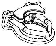
Minimum 90 in-lb Torque. Applications. NFB, NFX Series At A Glance. NFB and NFX Series Spring Return Direct Coupled Actuator
|
|
|
- Wesley Warner
- 6 years ago
- Views:
Transcription
1 NFB and NFX Series Spring Return Direct Coupled Actuator Minimum 90 in-lb Torque For damper areas up to sq-ft* Applications 1 3/4 1/ New standard clamp fits standard 1/ shafts to 1.05 jackshafts. Mount directly to 1.05 jackshafts. Linkage solutions are available when direct coupling is not possible. Actuators in bold have BDCM NFB, NFX Series At A Glance NFB4 NFX4 (p. 67) NFB4-S NFX4-S (p. 67) NFBUP NFXUP (p. 69) NFBUP-S NFXUP-S (p. 69) NFB4-SR NFX4-SR (p. 71) NFB4-SR-S NFX4-SR-S (p. 71) NFB4-MFT NFX4-MFT (p. 73) NFB4-MFT-S NFX4-MFT-S (p. 73) Torque: 90 in-lb Power supply: 4 VAC 10 VAC 30 VAC Control signal: On/Off Proportional to 10 VDC Multi-function** Feedback signal: to 10 VDC VDC variable** Running time motor: <75 sec 95 sec constant Adj. 40 to 0 sec.*** spring: <0 sec Brushless DC Motor External direction of rotation switch Appliance rated cable, 18 GA Built-in auxiliary switches two SPDT Installation instructions...(p ) General wiring... (p. 91) Start-up and checkout (p. 9) *Based on 4 in-lb/ft damper torque loading. Parallel blade. No edge seals. **Default to 10 VDC. ***Default 150 seconds. 65

2 NFB, NFX` Series Spring Return Direct Coupled Actuator A CLOSER LOOK Cut labor costs with simple direct coupling. True mechanical spring return the most reliable fail-safe. Mount for clockwise or counterclockwise fail-safe. Check damper position easily with clear position indicator. Don t worry about actuator burn-out. Belimo is overload-proof throughout rotation. Built-in mechanical stop to adjust angle of rotation. Manual override crank speeds installation Need to change control direction? Do it easily with a simple switch (modulating actuators). Incorporated breather membrane optimizes performance in harsh airstream environments. Built-in auxiliary switches are easy to use, offers feedback or signal for additional device (-S models). Microprocessor-controlled brushless DC motor increases actuator life span and reliability, provides constant running time (modulating actuators). Rugged metal on plastic housing withstands rough handling in the mechanical room. Standard 3 ft. appliance rated cable and conduit connector eases installation. Added flexibility to select clamp, electrical connection, and running time to fit your specific application with Belimo s customized line of actuators (NFX). The Belimo Difference Customer Commitment. Extensive product range. Application assistance. Same-day shipments. Free technical support. Five year warranty. Low Installation and Life-Cycle Cost. Easy installation. Accuracy and repeatability. Low power consumption. No maintenance. Long Service Life. Components tested before assembly. Every product tested before shipment. 30+ years direct coupled actuator design. 66
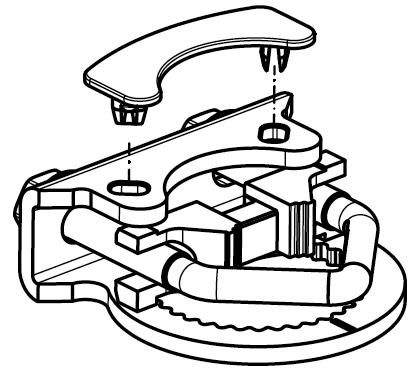
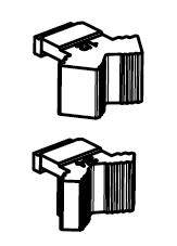
3 NFB4, NFB4-S, NFX4, NFX4-S On/Off, Spring Return, 4 V Torque min. 90 in-lb, for control of air dampers Technical Data Power supply Power consumption Transformer sizing Electrical connection NFB4... NFX4... Overload protection Control Torque Direction of rotation Mechanical angle of rotation Running time NFB4, NFB4-S, NFX4, NFX4-S 4 VAC ± 0% 50/60 Hz 4 VDC +0% / -10% running 6 W holding.5 W 8.5 VA (class power source) 3 ft, 18 GA appliance cable, 1/" conduit connector -S models: two 3 ft, 18 gauge appliance cables with 1/ conduit connectors 3 ft [1m], 10 ft [3m] or 16 ft [5m] 18 GA appliance or plenum cables, with or without 1/ conduit connector -S models: two 3 ft [1m], 10 ft [3m] or 16 ft [5m] appliance cables, with or without 1/" conduit connectors electronic throughout 0 to 95 rotation on/off 90 in-lb [10 Nm] minimum spring reversible with CW/CCW mounting 95 (adjustable with mechanical end stop, 35 to 95 ) motor < 75 seconds spring 0 -4 F to 1 F [-0 C to 50 C]; < 60 - F [-30 C] Position indication visual indicator, 0 to 95 (0 is full spring return position) Manual override 5 mm hex crank (³ ₁₆" Allen), supplied Humidity max. 95% RH non-condensing Ambient temperature - F to 1 F [-30 C to 50 C] Storage temperature -40 F to 176 F [-40 C to 80 C] Housing Nema, IP54, Enclosure Type Housing material zinc coated metal and plastic casing Agency listings culus acc. to UL A/--14, CAN/CSA E :0, CE acc. to 004/108/EC & 006/95/EC Noise level <50dB(A) 75 seconds 6dB(A) spring return Servicing maintenance free Quality standard ISO 9001 Weight 4.15 lbs (1.9 kg); 4.4 lbs (.0 kg) with switches Rated Impulse Voltage 800V, Type of action 1.AA (1.AA.B for -S version), Control Pollution Degree 3. NFB4-S, NFX4-S Auxiliary switches x SPDT 3A 50 VAC, UL approved one set at +10, one adjustable 10 to 90 Application For On/Off, fail-safe control of dampers in HVAC systems. Actuator sizing should be done in accordance with the damper manufacturer s specifications. Control is On/Off from an auxiliary contact, or a manual switch. The actuator is mounted directly to a damper shaft up to 1.05 in diameter by means of its universal clamp. A crank arm and several mounting brackets are available for applications where the actuator cannot be direct coupled to the damper shaft. Operation The NFB and NFX series actuators provide true spring return operation for reliable failsafe application and positive close off on air tight dampers. The spring return system provides constant torque to the damper with, and without, power applied to the actuator. The NFB and NFX series provides 95 of rotation and is provided with a graduated position indicator showing 0 to 95. The actuator may be stalled anywhere in its normal rotation without the need of mechanical end switches. The NFB4-S and NFX4-S versions are provided with two built-in auxiliary switches. These SPDT switches are provided for safety interfacing or signaling, for example, for fan start-up. The switching function at the fail-safe position is fixed at +10, the other switch function is adjustable between +10 to +90. The NFB4, NFB4-S, NFX4 and NFX4-S actuator is shipped at +5 (5 from full fail-safe) to provide automatic compression against damper gaskets for tight shut-off. Dimensions (Inches [mm]) K7- (supplied) 1/" Centered (Default) 3/4" Centered (Field Selectable) 1.05" Centered (Field Selectable) WAFBNFBDim 67
4 NFB4, NFB4-S, NFX4, NFX4-S On/Off, Spring Return, 4 V Accessories AV 8-5 Shaft extension IND-AFB Damper position indicator KH-AFB Crank arm K7- Universal clamp for up to 1.05 dia jackshafts TF-CC US Conduit fitting Tool-06 8mm and 10 mm wrench ZG-100 Universal mounting bracket ZG-101 Universal mounting bracket ZG-118 Mounting bracket for Barber Colman MA 3../4.., Honeywell Mod III or IV or Johnson Series 100 replacement or new crank arm type installations ZG-AFB Crank arm adaptor kit ZG-AFB118 Crank arm adaptor kit ZS-100 Weather shield (metal) ZS-150 Weather shield (polycarbonate) ZS-60 Explosion-proof housing ZS-300 NEMA 4X housing Note: When using NFB4, NFB4-S, NFX4, NFX4-S actuators, only use accessories listed on this page. For actuator wiring information and diagrams, refer to Belimo Wiring Guide. Typical Specification On/Off spring return damper actuators shall be direct coupled type which require no crank arm and linkage and be capable of direct mounting to a jackshaft up to a 1.05 diameter. The actuators must be designed so that they may be used for either clockwise or counterclockwise fail-safe operation. Actuators shall be protected from overload at all angles of rotation. If required, two SPDT auxiliary switch shall be provided having the capability of one being adjustable. Actuators with auxiliary switches must be constructed to meet the requirements for Double Insulation so an electrical ground is not required to meet agency listings. Actuators shall be culus Approved and have a 5 year warranty, and be manufactured under ISO 9001 International Quality Control Standards. Actuators shall be as manufactured by Belimo. Wiring Diagrams 1 Provide overload protection and disconnect as required. CAUTION Equipment Damage! Actuators may be connected in parallel. Power consumption and input impedance must be observed. 3 Actuators may also be powered by 4 VDC. 4 For end position indication, interlock control, fan startup, etc., NFB4-S and NFX4-S incorporates two built-in auxiliary switches: x SPDT, 3A VAC, UL Approved, one switch is fi xed at +10, one is adjustable 10 to 90. Meets culus requirements without the need of an electrical ground connection. WARNING Live Electrical Components! During installation, testing, servicing and troubleshooting of this product, it may be necessary to work with live electrical components. Have a qualifi ed licensed electrician or other individual who has been properly trained in handling live electrical components perform these tasks. Failure to follow all electrical safety precautions when exposed to live electrical components could result in death or serious injury. 1 4 VAC Transformer Line 1 Common Volts + Hot 3 On/Off wiring for NFB4, NFX4 NFB4, NFB4-S NFX4, NFX4-S W063_NFB(X) Auxiliary Switches for NFB4-S, NFX4-S NFB4-S NFX4-S W064_NFB(X)_-S 68
5 NFBUP, NFBUP-S, NFXUP, NFXUP-S On/Off, Spring Return, 4 to 40 VAC Torque min. 90 in-lb, for control of air dampers Technical Data Power supply Power consumption Transformer sizing Electrical connection NFBUP... NFXUP... Overload protection Control Torque Direction of rotation Mechanical angle of rotation Running time NFBUP, NFBUP-S, NFXUP, NFXUP-S VAC -0% / +10%, 50/60 Hz VDC ±10% running 6 W holding.5 W 6 4 VAC (class power source) VAC VAC 3 ft, 18 GA appliance cable, 1/" conduit connector -S models: Two 3 ft, 18 gauge appliance cables with 1/ conduit connectors 3 ft [1m], 10 ft [3m] or 16 ft [5m] 18 GA appliance cable, with or without 1/ conduit connector -S models: two 3 ft [1m], 10 ft [3m] or 16 ft [5m] appliance cables with or without 1/" conduit connectors electronic throughout 0 to 95 rotation on/off 90 in-lb [10 Nm] minimum spring reversible with CW/CCW mounting 95 (adjustable with mechanical end stop, 35 to 95 ) motor < 75 seconds spring 0 -4 F to 1 F [-0 C to 50 C]; < 60 - F [-30 C] Position indication visual indicator, 0 to 95 (0 is full spring return position) Manual override 5 mm hex crank (³ ₁₆" Allen), supplied Humidity max. 95% RH non-condensing Ambient temperature - F to 1 F [-30 C to 50 C] Storage temperature -40 F to 176 F [-40 C to 80 C] Housing Nema, IP54, Enclosure Type Housing material zinc coated metal and plastic casing Agency listings culus acc. to UL A/--14, CAN/CSA E :0, CE acc. to 004/108/EC & 006/95/EC Noise level <50dB(A) 75 seconds 6dB(A) spring return Servicing maintenance free Quality standard ISO 9001 Weight 4.15 lbs (1.9 kg), 4.4 lbs (.0 kg) with switches Rated Impulse Voltage 4kV, Type of action 1.AA (1.AA.B for -S version), Control Pollution Degree 3. NFBUP-S, NFXUP-S Auxiliary switches x SPDT 3A 50 VAC, UL approved one set at +10, one adjustable 10 to 90 Application For On/Off, fail-safe control of dampers in HVAC systems. Actuator sizing should be done in accordance with the damper manufacturer s specifications. Control is On/Off from an auxiliary contact, or a manual switch. The actuator is mounted directly to a damper shaft up to 1.05 in diameter by means of its universal clamp. A crank arm and several mounting brackets are available for applications where the actuator cannot be direct coupled to the damper shaft. Operation The NFB and NFX series actuators provide true spring return operation for reliable failsafe application and positive close off on air tight dampers. The spring return system provides constant torque to the damper with, and without, power applied to the actuator. The NFB and NFX series provides 95 of rotation and is provided with a graduated position indicator showing 0 to 95. The actuator may be stalled anywhere in its normal rotation without the need of mechanical end switches. The NFBUP-S and NFXUP-S versions are provided with two built-in auxiliary switches. These SPDT switches provide safety interfacing or signaling, for example, for fan startup. The switching function at the fail-safe position is fixed at +10, the other switch function is adjustable between +10 to +90. The NFBUP, NFBUP-S, NFXUP and NFXUP-S actuator is shipped at +5 (5 from full fail-safe) to provide automatic compression against damper gaskets for tight shut-off. Dimensions (Inches [mm]) K7- (supplied) 1/" Centered (Default) 3/4" Centered (Field Selectable) 1.05" Centered (Field Selectable) WAFBNFBDim 69
6 NFBUP, NFBUP-S, NFXUP, NFXUP-S On/Off, Spring Return, 4 to 40 VAC Accessories AV 8-5 Shaft extension IND-AFB Damper position indicator K7- Universal clamp for up to 1.05 dia jackshafts KH-AFB Crank arm TF-CC US Conduit fitting Tool-06 8mm and 10 mm wrench ZG-100 Universal mounting bracket ZG-101 Universal mounting bracket ZG-118 Mounting bracket for Barber Colman MA 3../4.., Honeywell Mod III or IV or Johnson Series 100 replacement or new crank arm type installations ZG-AFB Crank arm adaptor kit ZG-AFB118 Crank arm adaptor kit ZS-100 Weather shield (metal) ZS-150 Weather shield (polycarbonate) ZS-60 Explosion-proof housing ZS-300 NEMA 4X housing Note: When using NFBUP, NFBUP-S, NFXUP, NFXUP-S actuators, only use accessories listed on this page. For actuator wiring information and diagrams, refer to Belimo Wiring Guide. Typical Specification On/Off spring return damper actuators shall be direct coupled type which require no crank arm and linkage and be capable of direct mounting to a jackshaft up to a 1.05 diameter. The actuators must be designed so that they may be used for either clockwise or counterclockwise fail-safe operation. Actuators shall be protected from overload at all angles of rotation. If required, two SPDT auxiliary switch shall be provided having the capability of one being adjustable. Actuators with auxiliary switches must be constructed to meet the requirements for Double Insulation so an electrical ground is not required to meet agency listings. Actuators shall be culus Approved and have a 5 year warranty, and be manufactured under ISO 9001 International Quality Control Standards. Actuators shall be as manufactured by Belimo. Wiring Diagrams 1 Provide overload protection and disconnect as required. CAUTION Equipment Damage! Actuators may be connected in parallel. Power consumption and input impedance must be observed. 3 No ground connection is required. 4 For end position indication, interlock control, fan startup, etc., NFBUP-S and NFXUP-S incorporates two built-in auxiliary switches: x SPDT, 3A VAC, UL Approved, one switch is fi xed at +10, one is adjustable 10 to 90. Meets culus requirements without the need of an electrical ground connection. WARNING Live Electrical Components! During installation, testing, servicing and troubleshooting of this product, it may be necessary to work with live electrical components. Have a qualifi ed licensed electrician or other individual who has been properly trained in handling live electrical components perform these tasks. Failure to follow all electrical safety precautions when exposed to live electrical components could result in death or serious injury. W066_NFB(X)UP NFBUP, NFBUP-S NFXUP, NFBUP-S On/Off wiring for NFBUP, NFXUP Wht Blk W067_NFB(X)UP-S Auxiliary Switches for NFBUP-S, NFXUP-S NFBUP-S NFXUP-S 70

7 NFB4-SR, NFB4-SR-S, NFX4-SR, NFX4-SR-S Proportional, Spring Return, 4 V, for or 10 VDC or 4 to 0 ma Control Signal Torque min. 90 in-lb, for control of air dampers Technical Data Power supply Power consumption Transformer sizing Electrical connection NFB... NFX... Overload protection Operating range Y Input impedance Feedback output U Torque Direction of rotation Mechanical angle of rotation Running time NFB4-SR, NFB4-SR-S, NFX4-SR, NFX4-SR-S 4 VAC ±0%, 50/60 Hz 4 VDC +0% / -10% running 3.5 W holding.5 W 6 VA (class power source) 3 ft, 18 GA appliance cable, 1/" conduit connector -S models: two 3 ft, 18 gauge appliance cables with 1/ conduit connectors 3 ft [1m], 10 ft [3m] or 16 ft [5m] 18 GA appliance or plenum cables, with or without 1/ conduit connector -S models: Two 3 ft [1m], 10 ft [3m] or 16 ft [5m] appliance cables, with or without 1/" conduit connectors electronic throughout 0 to 95 rotation to 10 VDC, 4 to 0mA 100 kω for to 10 VDC (0.1 ma) 500 Ω for 4 to 0 ma to 10 VDC (max. 0.5 ma) 90 in-lb [10 Nm] minimum spring reversible with CW/CCW mounting motor reversible with built-in switch 95 (adjustable with mechanical end stop, 35 to 95 ) spring < 0 -4 F to 1 F [-0 C to 50 C]; < 60 - F [-30 C] motor 95 seconds Position indication visual indicator, 0 to 95 (0 is full spring return position) Manual override 5 mm hex crank (³ ₁₆" Allen), supplied Humidity max. 95% RH non-condensing Ambient temperature - F to 1 F [-30 C to 50 C] Storage temperature -40 F to 176 F [-40 C to 80 C] Housing Nema, IP54, Enclosure Type Housing material zinc coated metal and plastic casing Agency listings culus acc. to UL A/--14, CAN/CSA E :0, CE acc. to 004/108/EC & 006/95/EC Noise level 40dB(A) 95 seconds 6dB(A) spring return Servicing maintenance free Quality standard ISO 9001 Weight 4.15 lbs (1.9 kg); 4.4 lbs (.0 kg) with switches Rated Impulse Voltage 800V, Type of action 1.AA (1.AA.B for -S version), Control Pollution Degree 3. NFB4-SR-S, NFX4-SR-S Auxiliary switches x SPDT 3A 50 VAC, UL approved one set at +10, one adjustable 10 to 90 Application For proportional modulation of dampers in HVAC systems. Actuator sizing should be done in accordance with the damper manufacturer s specifications. The actuator is mounted directly to a damper shaft up to 1.05 in diameter by means of its universal clamp. A crank arm and several mounting brackets are available for applications where the actuator cannot be direct coupled to the damper shaft. The actuator operates in response to a to 10 VDC, or with the addition of a 500Ω resistor, a 4 to 0 ma control input from an electronic controller or positioner. A to 10 VDC feedback signal is provided for position indication. Not to be used for a master-slave application. Operation The NFB and NFX series actuators provide true spring return operation for reliable failsafe application and positive close-off on air tight dampers. The spring return system provides constant torque to the damper with, and without, power applied to the actuator. The NFB and NFX series provides 95 of rotation and is provided with a graduated position indicator showing 0 to 95. The NFB4-SR and NFX4-SR uses a brushless DC motor which is controlled by an Application Specific Integrated Circuit (ASIC) and a microprocessor. The microprocessor provides the intelligence to the ASIC to provide a constant rotation rate and to know the actuator s exact fail-safe position. The ASIC monitors and controls the brushless DC motor s rotation and provides a digital rotation sensing function to prevent damage to the actuator in a stall condition. The actuator may be stalled anywhere in its normal rotation without the need of mechanical end switches. The NFB4-SR-S and NFX4-SR-S versions are provided with two built-in auxiliary switches. These SPDT switches provide safety interfacing or signaling, for example, for fan start-up. The switching function at the fail-safe position is fixed at +10, the other switch function is adjustable between +10 to +90. The NFB4-SR, NFB4-SR-S, NFX4-SR and NFX4-SR-S actuator is shipped at +5 (5 from full fail-safe) to provide automatic compression against damper gaskets for tight shut-off. Dimensions (Inches [mm]) K7- (supplied) 1/" Centered (Default) 3/4" Centered (Field Selectable) 1.05" Centered (Field Selectable) WAFBNFBDim 71
8 NFB4-SR, NFB4-SR-S, NFX4-SR, NFX4-SR-S Proportional, Spring Return, 4 V, for or 10 VDC to 4 to 0 ma Control Signal Accessories AV 8-5 Shaft extension IND-AFB Damper position indicator KH-AFB Crank arm K7- Universal clamp for up to 1.05 dia jackshafts TF-CC US Conduit fitting Tool-06 8mm and 10 mm wrench ZG-100 Universal mounting bracket ZG-101 Universal mounting bracket ZG-118 Mounting bracket for Barber Colman MA 3../4.., Honeywell Mod III or IV or Johnson Series 100 replacement or new crank arm type installations ZG-AFB Crank arm adaptor kit ZG-AFB118 Crank arm adaptor kit ZS-100 Weather shield (metal) ZS-150 Weather shield (polycarbonate) ZS-60 Explosion-proof housing ZS-300 NEMA 4X housing NOTE: When using NFB4-SR, NFB4-SR-S, NFX4-SR and NFX4-SR-S actuators, only use accessories listed on this page. For actuator wiring information and diagrams, refer to Belimo Wiring Guide. Typical Specification Spring return control damper actuators shall be direct coupled type which require no crank arm and linkage and be capable of direct mounting to a jackshaft up to a 1.05 diameter. The actuator must provide proportional damper control in response to a to 10 VDC or, with the addition of a 500Ω resistor, a 4 to 0 ma control input from an electronic controller or positioner. The actuators must be designed so that they may be used for either clockwise or counterclockwise fail-safe operation. Actuators shall use a brushless DC motor controlled by a microprocessor and be protected from overload at all angles of rotation. Run time shall be constant, and independent of torque. A to 10 VDC feedback signal shall be provided for position feedback. Actuators shall be culus Approved and have a 5 year warranty, and be manufactured under ISO 9001 International Quality Control Standards. Actuators shall be as manufactured by Belimo. Wiring Diagrams WARNING Live Electrical Components! During installation, testing, servicing and troubleshooting of this product, it may be necessary to work with live electrical components. Have a qualifi ed licensed electrician or other individual who has been properly trained in handling live electrical components perform these tasks. Failure to follow all electrical safety precautions when exposed to live electrical components could result in death or serious injury. 1 Line Volts 4 VAC Transformer Control Signal ( ) to 10 VDC (+) to 10 VDC control of NFB4-SR and NFX4-SR 4 to 0 ma control of NFB4-SR and NFX4-SR with to 10 VDC feedback output 1 Common 3 + Hot 3 Y 1 Input, to 10V 5 U Output to 10V NFB4-SR, NFB4-SR-S NFX4-SR, NFX4-SR-S NFB4-SR, NFB4-SR-S NFX4-SR, NFX4-SR-S W068_NFB(X)4-SR W069_NFB(X)4-SR 1 Provide overload protection and disconnect as required. CAUTION Equipment Damage! Actuators may be connected in parallel. Power consumption and input impedance must be observed. Up to 4 actuators may be connected in parallel. With 4 actuators wired to one 500 Ω resistor. Power consumption must be observed. 3 Actuator may also be powered by 4 VDC. 4 For end position indication, interlock control, fan startup, etc., NFB4-SR-S and NFX4-SR-S incorporates two built-in auxiliary switches: x SPDT, 3A VAC, UL Approved, one switch is fi xed at +10, one is adjustable 10 to Only connect common to neg. ( ) leg of control circuits NFB4-SR-S NFX4-SR-S Auxiliary switches for NFB4-SR-S, NFX4-SR-S W064_NFB(X)4_SR_-S The ZG-R Ω resistor converts the 4 to 0 ma control signal to to 10 VDC. 7
 Feedback to 10 VDC (DEFAULT) Technical Data Power supply Power consumption Transformer sizing Electrical connection NFB... NFX.")
9 NFB4-MFT, NFB4-MFT-S, NFX4-MFT, NFX4-MFT-S Proportional, Spring Return, Multi-Function Technology Torque min. 90 in-lb Control to 10 VDC (DEFAULT) Feedback to 10 VDC (DEFAULT) Technical Data Power supply Power consumption Transformer sizing Electrical connection NFB... NFX... Overload protection Operating range Y* Input impedance Feedback output U* Torque Direction of rotation* Mechanical angle of rotation* Running time NFB4-MFT, NFB4-MFT-S, NFX4-MFT, NFX4-MFT-S 4 VAC ±0%, 50/60 Hz 4 VDC +0% / -10% running 6.5 W holding 3 W 9 VA (class power source) 3 ft, 18 GA appliance cable, 1/" conduit connector -S models: two 3 ft, 18 gauge appliance cables with 1/ conduit connectors 3 ft [1m], 10 ft [3m] or 16 ft [5m] 18 GA appliance or plenum cables, with or without 1/ conduit connector -S models: Two 3 ft [1m], 10 ft [3m] or 16 ft [5m] appliance cables with or without 1/" conduit connectors electronic throughout 0 to 95 rotation to 10 VDC, 4 to 0mA (default) variable (VDC, PWM, floating point, on/off) 100 kω for to 10 VDC (0.1 ma) 500 Ω for 4 to 0 ma 1500 Ω for PWM, floating point, on/off to 10 VDC (max. 0.5 ma) 90 in-lb [10 Nm] minimum spring reversible with CW/CCW mounting motor reversible with built-in switch 95 (adjustable with mechanical end stop, 35 to 95 ) spring < 0 -4 F to 1 F [-0 C to 50 C]; < 60 - F [-30 C] motor* 150 seconds (default), variable (40 to 0 secs) off (Default) Angle of Rotation Adaptation* Override control* min position = 0% mid. position = 50% max. position = 100% Position indication visual indicator, 0 to 95 (0 is full spring return position) Manual override 5 mm hex crank (³ ₁₆" Allen), supplied Humidity max. 95% RH non-condensing Ambient temperature - F to 1 F [-30 C to 50 C] Storage temperature -40 F to 176 F [-40 C to 80 C] Housing Nema, IP54, Enclosure Type Housing material zinc coated metal and plastic casing Agency listings culus acc. to UL A/--14, CAN/CSA E :0, CE acc. to 004/108/EC & 006/95/EC Noise level 40dB(A) 150 seconds, run time dependent 6dB(A) spring return Servicing maintenance free Quality standard ISO 9001 Weight 4. lbs (1.9 kg), 4.4 lbs (.0 kg) with switches *Variable when configured with MFT options. Rated Impulse Voltage 800V, Type of action 1.AA (1.AA.B for -S version), Control Pollution Degree 3. Programmed for 40 sec motor run time. At 150 sec motor run time, transformer sizing is 6.5 VA and power consumption is 4.5 W running / 3 W holding. NFB4-MFT-S, NFX4-MFT-S Auxiliary switches x SPDT 3A 50 VAC, UL approved one set at +10, one adjustable 10 to 90 Application For proportional modulation of dampers and control valves in HVAC systems. The NFB4-MFT and NFX4-MFT provides mechanical spring return operation for reliable fail-safe application. Default/Configuration Default parameters for to 10 VDC applications of the NFB4-MFT and NFX4-MFT actuator are assigned during manufacturing. If required, custom versions of the actuator can be ordered. The parameters noted in the Technical Data table are variable. These parameters can be changed by three means: Pre-set configurations from Belimo Custom configurations from Belimo Configurations set by the customer using the MFT PC tool (version 3.4 or higher) software application. Handheld ZTH-GEN Operation The NFB4-MFT, NFX4-MFT actuator provides 95 of rotation and is provided with a graduated position indicator showing 0 to 95. The actuator will synchronize the 0 mechanical stop or the damper or valves mechanical stop and use this point for its zero position during normal control operations. The actuator uses a brushless DC motor which is controlled by an Application Specific Integrated Circuit (ASIC) and a microprocessor. The microprocessor provides the intelligence to the ASIC to provide a constant rotation rate and to know the actuator s exact position. The ASIC monitors and controls the brushless DC motor s rotation and provides a Digital Rotation Sensing (DRS) function to prevent damage to the actuator in a stall condition. The position feedback signal is generated with out the need for mechanical feedback potentiometers using DRS. The actuator may be stalled anywhere in its normal rotation without the need of mechanical end switches. The NFB4-MFT, NFB4-MFT-S, NFX4-MFT and NFX4-MFT-S is mounted directly to control shafts up to 1.05 diameter by means of its universal clamp and anti-rotation bracket. A crank arm and several mounting brackets are available for damper applications where the actuator cannot be direct coupled to the damper shaft. The spring return system provides minimum specified torque to the application during a power interruption. The NFB4-MFT, NFB4-MFT-S, NFX4-MFT and NFX4-MFT-S actuator is shipped at +5 (5 from full fail-safe) to provide automatic compression against damper gaskets for tight shut-off. NOTE: Refer to Multi-Function Technology documentation. Dimensions (Inches [mm]) K7- (supplied) 1/" Centered (Default) 3/4" Centered (Field Selectable) 1.05" Centered (Field Selectable) WAFBNFBDim 73
10 Accessories AV 8-5 Shaft extension IND-AFB Damper position indicator KH-AFB Crank arm K7- Universal clamp for up to 1.05 dia jackshafts TF-CC US Conduit fitting Tool-06 8mm and 10 mm wrench ZG-100 Universal mounting bracket ZG-101 Universal mounting bracket ZG-118 Mounting bracket for Barber Colman MA 3../4.., Honeywell Mod III or IV or Johnson Series 100 replacement or new crank arm type installations ZG-AFB Crank arm adaptor kit ZG-AFB118 Crank arm adaptor kit ZS-100 Weather shield (metal) ZS-150 Weather shield (polycarbonate) ZS-60 Explosion-proof housing ZS-300 NEMA 4X housing NOTE: When using NFB4-MFT, NFB4-MFT-S, NFX4-MFT and NFX4-MFT-S actuators, only use accessories listed on this page. For actuator wiring information and diagrams, refer to Belimo Wiring Guide. Typical Specification NFB4-MFT, NFB4-MFT-S, NFX4-MFT, NFX4-MFT-S Proportional, Spring Return, Multi-Function Technology Auxiliary Switches for NFB4-MFT-S, NFX4-MFT-S NFB4-MFT-S NFX4-MFT-S W600_A W399_08 Spring return control damper actuators shall be direct coupled type which require no crank arm and linkage and be capable of direct mounting to a jackshaft up to a 1.05 diameter. The actuator must provide proportional damper control in response to a to 10 VDC or, with the addition of a 500Ω resistor, a 4 to 0 ma control input from an electronic controller or positioner. The actuators must be designed so that they may be used for either clockwise or counterclockwise fail-safe operation. Actuators shall use a brushless DC motor controlled by a microprocessor and be protected from overload at all angles of rotation. Run time shall be constant, and independent of torque. A to 10 VDC feedback signal shall be provided for position feedback. Actuators shall be culus Approved and have a 5 year warranty, and be manufactured under ISO 9001 International Quality Control Standards. Actuators shall be as manufactured by Belimo. VDC/4-0 ma W399_08 Wiring Diagrams 1 Provide overload protection and disconnect as required. CAUTION Equipment Damage! Actuators may be connected in parallel if not mechanically mounted to the same shaft. Power consumption and input impedance must be observed. 3 Actuators may also be powered by 4 VDC. Position feedback cannot be used with Triac sink controller. 4 The actuator internal common reference is not compatible. Control signal may be pulsed from either the Hot (source) 5 or the Common (sink) 4 VAC line. Contact closures A & B also can be triacs. 8 A & B should both be closed for triac source and open for triac sink. For triac sink the common connection from the actuator 9 must be connected to the hot connection of the controller. Meets UL requirements without the need of an electrical ground connection. PWM On/Off control W399_08 W399_08 The ZG-R Ω resistor may be used. WARNING Live Electrical Components! During installation, testing, servicing and troubleshooting of this product, it may be necessary to work with live electrical components. Have a qualifi ed licensed electrician or other individual who has been properly trained in handling live electrical components perform these tasks. Failure to follow all electrical safety precautions when exposed to live electrical components could result in death or serious injury. Floating Point control 74
![Product Cross Reference Current to New Generation NF10 US, NF10-S US NFBUP, NFBUP-S, NFXUP, NFXUP-S Torque 60 in-lb [7 Nm] minimum 90 in-lb.](/docs-images/75/72188906/images/11-0.jpg "[10 Nm] minimum OPERATION Running Time Noise Level Motor < 75 seconds <75 seconds Spring < 60 seconds Max.")
11 Product Cross Reference Current to New Generation NF10 US, NF10-S US NFBUP, NFBUP-S, NFXUP, NFXUP-S Torque 60 in-lb [7 Nm] minimum 90 in-lb. [10 Nm] minimum OPERATION Running Time Noise Level Motor < 75 seconds <75 seconds Spring < 60 seconds Max. 45 db (A) 0 -4 F to 1 F [-0 C to 50 C]; <60 - F [-30 C] <50dB(A) 75 seconds; 6dB(A) Spring Return Motor Technology DC Motor DC Motor Overload Protection Electronic throughout 0 to 95 rotation Electronic throughout 0 to 95 rotation Operating Temperature - F to 1 F [-30 C to 50 C] - F to 1 F [-30 C to 50 C] Operating Humidity 5 to 95% RH non-condensing 5 to 95% RH, non-condensing CONTROL Control Signal On/Off On/Off 0.65" [16.5] MOUNTING & COMMISSIONING Dimensions (L x W x H) 3.86" [98] 3.5" [8.7] 3.15" [80].4" [57] 0.19" [5] 0.39" [10] 0.35" [9].64" [67] 1.97" [50] 10.47" [66] 5.85" [148.5] 0.6" [6.5] With Conduit Fitting 10.47" [66] x 3.86" [98] x 3.5" [8.7] 9.69" [46] x 3.86" [98] x 3.4" [87] Shaft Dimensions Up to 1.05 Up to 1.05 Direction of Rotation Reversible with CW/CCW mounting Reversible with CW/CCW mounting Manual Override Position Indication Angle of Rotation Visual indicator, 0 to 95 (0 is Spring Return position) 95, adjustable 30 to 95 w/ ZDB-AF US accessory N/A 1.93" [49] 5 mm hex crank (3/16" Allen), supplied Visual indicator, 0 to 95 (0 is Spring Return position) 95 (adjustable with mechanical end stop, 35 to 95 ) 75
: 1 x SPDT 7A (.")
 @ 50V UL Approved, one set at + 10, one adjustable 10 to 90 Electrical Connection 3 ft, 18 GA appliance cable 1/ conduit connector, (-S Models): Two 3 ft, 18 GA, appliance cables, ½\"")
12 Product Cross Reference Current to New Generation Power Supply NF10 US, NF10-S US 10 VAC ± 10% 50/60 Hz NFBUP, NFBUP-S, NFXUP, NFXUP-S 4 40 VAC -0 %/+10%, 50/60 Hz; 4 15 VDC +/- 10 % Power Consumption Running 7 W 6 W Holding 4 W.5 W Transformer Sizing 9.5 VA 6 4 VAC VAC VAC ELECTRICAL WIRING Auxiliary Switches (-S Models): 1 x SPDT 7A 50 VAC, UL Approved, adjustable 5 to 85 (-S Models): Two SPDT 3A (0.5A 50V UL Approved, one set at + 10, one adjustable 10 to 90 Electrical Connection 3 ft, 18 GA appliance cable 1/ conduit connector, (-S Models): Two 3 ft, 18 GA, appliance cables, ½" conduit connectors 3 ft, 18 GA, appliance cable, ½" conduit connector, (-S Models): Two 3 ft, 18 GA, appliance cables, ½" conduit connectors; Optional 10 or 16 ft cables with X types CONSTRUCTION Housing Rating NEMA, IP54 NEMA, IP54, Enclosure Type Housing Material Zinc coated steel Zinc coated metal and plastic casing Agency Listings culus acc. to UL 873 and CAN/CSA C. No culus acc. to UL A/--14, CAN/CSA E :0, CE acc. to 004/108/EC & 006/95/EC Storage Temperature -40 F to 176 F [-40 C to 80 C] -40 F to 176 F [-40 C to 80 C] Weight 7.3 lbs (3.3 kg) 4.15 lbs (1.9 kg), (-S Models): 4.4 lbs (.0 kg) 76
13 Product Cross Reference Current to New Generation NF4 US, NF4-S US, NF4-S US NFB4, NFB4-S, NFX4, NFX4-S Torque 60 in-lb [7 Nm] minimum 90 in-lb. [10 Nm] minimum OPERATION Running Time Noise Level Motor < 75 seconds < 75 seconds Spring < 60 seconds Max. 45 db(a) 0 -4 F to 1 F [-0 C to 50 C]; <60 - F [-30 C] <50 db(a) 75 seconds; 6 db(a) Spring Return Motor Technology DC Motor DC Motor Overload Protection Electronic throughout 0 to 95 rotation Electronic throughout 0 to 95 rotation Operating Temperature - F to 1 F [-30 C to 50 C] - F to 1 F [-30 C to 50 C] Operating Humidity 5 to 95% RH non-condensing 5 to 95% RH, non-condensing CONTROL Control Signal On/Off On/Off 0.65" [16.5] Dimensions (L x W x H) [mm] 3.86" [98] 3.5" [8.7] 3.15" [80].4" [57] 0.19" [5] 0.39" [10] 0.35" [9].64" [67] 10.47" [66] 5.85" [148.5] 0.6" [6.5] 1.93" [49] MOUNTING & COMMISSIONING 1.97" [50] With Conduit Fitting 10.47" [66] x 3.86" [98] x 3.5" [8.7] 9.69" [46] x 3.86" [98] x 3.4" [87] Shaft Dimensions Up to 1.05 Up to 1.05 Direction of Rotation Reversible with CW/CCW mounting Reversible with CW/CCW mounting Manual Override Position Indication Visual indicator, 0 to 95 (0 is Spring Return position) N/A 5 mm hex crank (3/16" Allen), supplied Visual indicator, 0 to 95 (0 is Spring Return position) Angle of Rotation 95, adjustable 30 to 95 w/ ZDB-AF US accessory 95 (adjustable with mechanical end stop, 35 to 95 ) 77
14 Product Cross Reference Current to New Generation NF4 US, NF4-S US, NF4-S US NFB4, NFB4-S, NFX4, NFX4-S Power Supply 4 VAC ± 0% 50/60 Hz; 4 VDC ± 10% 4 VAC, +/- 0%, 50/60 Hz; 4 VDC, +0/-10% Power Consumption Running 5 W 6 W Holding.6 W.5 W Transformer Sizing 8 VA (Class power source) 8.5 VA (Class power source) ELECTRICAL WIRING Auxiliary Switches (-S Models): 1 x SPDT 7A 50 VAC, UL Approved adjustable 5 to 85 ; (-S Models): x SPDT 7A 50 VAC, UL Approved one set at +5, one adjustable 5 to 85 (-S Models) Two SPDT 3A (0.5A 50V UL approved, one set at + 10, one adjustable 10 to 90 Electrical Connection 3 ft, 18 GA appliance cable, 1/ conduit connector; (-S and - S Models): Two 3 ft, 18 GA, appliance cables, ½" conduit connectors 3 ft, 18 GA, appliance cable, ½" conduit connector; (-S Models) Two 3 ft, 18 GA, appliance cables, ½" conduit connectors; Optional 10 or 16 ft cables and plenum rated cables (non -S models only) with X types CONSTRUCTION Housing Rating NEMA, IP54 NEMA, IP54, Enclosure Type Housing Material Zinc coated steel Zinc coated metal and plastic casing Agency Listings culus acc. to UL 873 and CAN/CSA C. No culus acc. to UL A/--14, CAN/CSA E :0, CE acc. to 004/108/EC & 006/95/EC Storage Temperature -40 F to 176 F [-40 C to 80 C] -40 F to 176 F [-40 C to 80 C] Weight 6.6 lbs (3.0 kg) 4.15 lbs (1.9 kg), (-S Models): 4.4 lbs (.0 kg) 78
15 Product Cross Reference Current to New Generation OPERATION CONTROL NF4-MFT US NFB4-MFT, NFB4-MFT-S, NFX4-MFT, NFX4-MFT-S Torque 60 in-lb (8 Nm) minimum 90 in-lb. [10 Nm] minimum Running Time Noise Level Motor Spring 150 seconds (default); variable (75 to 300 seconds) <60 seconds <45 db (A) 150 seconds (default), variable (40 to 0 seconds) 0 -4 F to 1 F [-0 C to 50 C]; <60 - F [-30 C] 40dB(A) 150 seconds, run time dependent; 6dB(A) Spring Return Motor Technology Brushless DC Motor Brushless DC Motor Overload Protection Electronic throughout 0 to 95 rotation Electronic throughout 0 to 95 rotation Operating Temperature - F to 1 F [-30 C to 50 C] - F to 1 F [-30 C to 50 C] Operating Humidity 5 to 95% RH, non-condensing 5 to 95% RH, non-condensing Operating Range 'Y' Input Impedance Feedback Output 'U' to 10 VDC, 4 to 0 ma w/500 resistor; Programmable Variable 100 k for to 10 VDC (0.1 ma); 500 for 4 to 0 ma; 1500 for PWM, Floating Point and On/Off to 10 VDC, 0.5 ma max, variable when configured with MFT options 0.65" [16.5] to 10 VDC, 4 to 0 ma w/500 resistor; Variable (VDC, PWM, Floating Point, On/Off) 100 k for to 10 VDC (0.1 ma); 500 for 4 to 0 ma; 1500 for PWM, Floating Point, On/Off to 10 VDC, 0.5mA max, variable when configured with MFT options Dimensions (L x W x H) [mm] 3.86" [98] 3.5" [8.7] 3.15" [80].4" [57] 0.19" [5] 0.39" [10] 0.35" [9].64" [67] 10.47" [66] 5.85" [148.5] 0.6" [6.5] 1.93" [49] MOUNTING & COMMISSIONING 1.97" [50] With Conduit Fitting 10.47" [66] x 3.86" [98] x 3.5" [8.7] 9.69" [46] x 3.86" [98] x 3.4" [87] Shaft Dimensions Up to 1.05" Up to 1.05" Direction of Rotation Manual Override Motor Reversible with builtin switch Reversible with built-in switch Spring Reversible with CW/CCW mounting Reversible with CW/CCW mounting N/A 5 mm hex crank (3/16" Allen), supplied Position Indication Visual indicator, 0 to 95 Visual indicator, 0 to 95 (0 is Spring Return position) 79
 Power Supply 4 VAC, ± 0%, 50/60 Hz; 4 VDC, ±10% 4 VAC, +/- 0%, 50/60 Hz; 4 VDC, +0/-10% Power Consumption Running 3 W 6.5 W Holding 1.")
16 Product Cross Reference Current to New Generation NF4-MFT US NFB4-MFT, NFB4-MFT-S, NFX4-MFT, NFX4-MFT-S MOUNTING & COMMISSIONING Angle of Rotation 95, adjustable 30 to 90 w/ ZDB-AF US accessory 95 (adjustable with mechanical end stop, 35 to 95 ) Power Supply 4 VAC, ± 0%, 50/60 Hz; 4 VDC, ±10% 4 VAC, +/- 0%, 50/60 Hz; 4 VDC, +0/-10% Power Consumption Running 3 W 6.5 W Holding 1.8 W 3 W ELECTRICAL WIRING Transformer Sizing 6 VA (Class power source) 9 VA (Class power source)* Auxiliary Switches Electrical Connection 3 ft, 18 GA, appliance cable, 1/ conduit connector N/A (-S Models): Two SPDT 3A (0.5A 50V UL approved, one set at + 10, one adjustable 10 to 90 3 ft, 18 GA, appliance cable, ½" conduit connector; (-S Models): Two 3 ft, 18 GA, appliance cables, ½" conduit connectors; Optional 10 or 16 ft cables and plenum rated cables (non -S models only) with X types CONSTRUCTION Housing Rating NEMA, IP54 NEMA, IP54, Enclosure Type Housing Material Zinc coated metal Zinc coated metal and plastic casing Agency Listings UL 873 listed, CSA C. No. 4 certified culus acc. to UL A/--14, CAN/CSA E :0, CE acc. to 004/108/EC & 006/95/EC Storage Temperature -40 F to 176 F [-40 C to 80 C] -40 F to 176 F [-40 C to 80 C] Weight 6.0 lbs. (.7 kg) 4. lbs (1.9 kg), (-S Models): 4.4 lbs.(.0 kg) * 9 40 second run time 80
![Product Cross Reference Current to New Generation NF4-SR US, NF4-SR-S US NFB4-SR, NFB4-SR-S, NFX4-SR, NFX4-SR-S Torque 60 in-lb [7 Nm] minimum 90 in-lb.](/docs-images/75/72188906/images/17-0.jpg "[10 Nm] minimum OPERATION Running Time Motor 150 seconds constant, independent of load 95 seconds Noise Level Spring < 60 seconds Max.")
17 Product Cross Reference Current to New Generation NF4-SR US, NF4-SR-S US NFB4-SR, NFB4-SR-S, NFX4-SR, NFX4-SR-S Torque 60 in-lb [7 Nm] minimum 90 in-lb. [10 Nm] minimum OPERATION Running Time Motor 150 seconds constant, independent of load 95 seconds Noise Level Spring < 60 seconds Max. 45 db (A) 0 -4 F to 1 F [-0 C to 50 C]; <60 - F [-30 C] 40dB(A) 95 seconds; 6dB(A) spring return Motor Technology Brushless DC Motor Brushless DC Motor Overload Protection Electronic throughout 0 to 95 rotation Electronic throughout 0 to 95 rotation Operating Temperature - F to +1 F [-30 C to +50 C] - F to 1 F [-30 C to 50 C] Operating Humidity 5 to 95% RH non-condensing 5 to 95% RH, non-condensing CONTROL Operating Range 'Y' to 10 VDC, 4 to 0mA to 10 VDC, 4 to 0 ma Input Impedance 100 k (0.1 ma), k for to 10 VDC (0.1 ma); 500 for 4 to 0 ma Feedback Output 'U' to 10 VDC (max. 0.5 ma) for 95 to 10 VDC (max 0.5 ma) 0.65" [16.5] Dimensions (L x W x H) [mm] 3.86" [98] 3.5" [8.7] 3.15" [80].4" [57] 0.19" [5] 0.39" [10] 0.35" [9].64" [67] 10.47" [66] 5.85" [148.5] 0.6" [6.5] 1.93" [49] MOUNTING & COMMISSIONING 1.97" [50] With Conduit Fitting 10.47" [66] x 3.86" [98] x 3.5" [8.7] 9.69" [46] x 3.86" [98] x 3.4" [87] Shaft Dimensions Up to 1.05 Up to 1.05 Direction of Rotation Manual Override Position Indication Motor Reversible with built-in switch Reversible with built-in switch Spring Reversible with CW/CCW mounting Reversible with CW/CCW mounting Visual indicator, 0 to 95 (0 is Spring Return position) N/A 5 mm hex crank (3/16" Allen), supplied Visual indicator, 0 to 95 (0 is Spring Return position) Angle of Rotation 95, adjustable 30 to 95 w/ ZDB-AF US accessory 95 (adjustable with mechanical end stop, 35 to 95 ) 81
18 Product Cross Reference Current to New Generation NF4-SR US, NF4-SR-S US NFB4-SR, NFB4-SR-S, NFX4-SR, NFX4-SR-S Power Supply 4 VAC ± 0% 50/60 Hz; 4 VDC ± 10% 4 VAC, +/- 0%, 50/60 Hz; 4 VDC, +0/-10% Power Consumption Running 3 W 3.5 W Holding 1 W.5 W Transformer Sizing 6 VA (Class power source) 6 VA (Class power source) ELECTRICAL WIRING Auxiliary Switches (-S Models): 1 x SPDT 7A 50 VAC, UL listed adjustable 5 to 85 (-S Models): Two SPDT 3A (0.5A 50V UL approved, one set at +10, one adjustable 10 to 90 Electrical Connection 3 ft, 18 GA appliance cable 1/ conduit connector; (-S Models): Two 3 ft, 18 GA, appliance cables, ½" conduit connectors 3 ft, 18 GA, appliance cable, ½" conduit connector; (-S Models): Two 3 ft, 18 GA, appliance cables, ½" conduit connectors; Optional 10 or 16 ft cables and plenum rated cables (non -S models only) with X types CONSTRUCTION Housing Rating NEMA, IP54 NEMA, IP54, Enclosure Type Housing Material Zinc coated metal Zinc coated metal and plastic casing Agency Listings UL 873 listed, CSA C. No.4 certified culus acc. to UL A/--14, CAN/CSA E :0, CE acc. to 004/108/EC & 006/95/EC Storage Temperature -40 F to +176 F [-40 C to +80 C] -40 F to 176 F [-40 C to 80 C] Weight 6.0 lbs (.7 kg) 4.15 lbs (1.9 kg), (-S Models):4.4 lbs (.0 kg) 8
19 Installation Instructions Quick-Mount Visual Instructions for Mechanical Installation Quick-Mount Visual Instructions 1. Rotate the damper to its failsafe position. If the shaft rotates counterclockwise, mount the CCW side of the actuator out. If it rotates clockwise, mount the actuator with the CW side out.. If the universal clamp is not on the correct side of the actuator, move it to the correct side for ease of installation. 3. Slide the actuator onto the shaft and tighten the nuts on the V-bolt with a 10mm wrench to 6-8 ft-lb of torque. 4. Slide the anti-rotation strap under the actuator so that it engages the slot at the base of the actuator. Secure the strap to the duct work with #8 self-tapping screws. NOTE: Read the Standard Mounting instructions, on the next page, for more detailed information. Dimensions (Inches [mm]) min. 3 1/ [90] min. 3/4 [0] CCW CCW CCW CCW CW CW 1/4" [6.35 mm] CCW CW..8 CW CW 1/4" [6.35 mm] 1/4" [6.35 mm] 1/4" [6.35 mm] 83

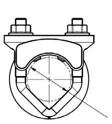
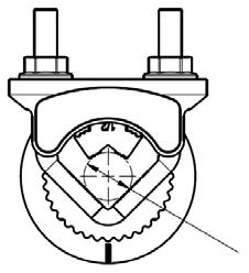
20 Installation Instructions K7- Universal Clamp 1 84
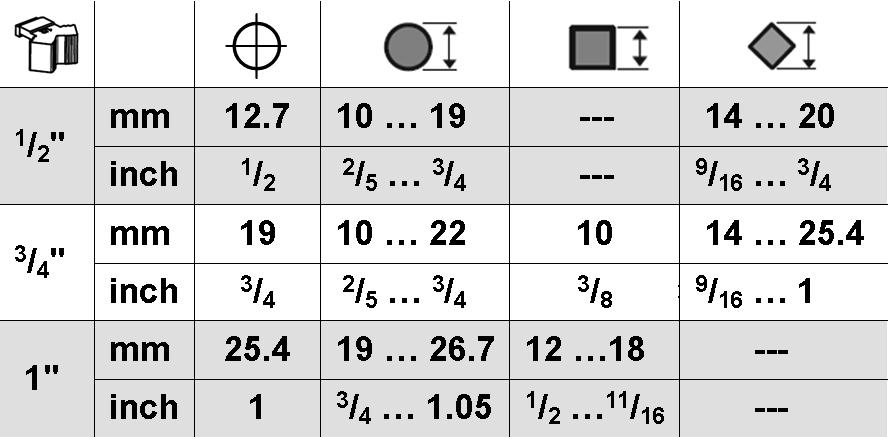
21 Installation Instructions Mechanical Installation Determining Torque Loading and Actuator Sizing Damper torque loadings, used in selecting the correct size actuator, should be provided by the damper manufacturer. If this information is not available, the following general selection guidelines can be used. Damper Type Opposed blade, without edge seals, for non-tight close-off applications Parallel blade, without edge seals, for non-tight close-off applications Opposed blade, with edge seals, for tight close-off applications Parallel blade, with edge seals, for tight close-off applications Torque Loading 3 in-lb/sq. ft. 4 in-lb/sq. ft. 5 in-lb/sq. ft. 7 in-lb/sq. ft. The above torque loadings will work for most applications with 1000 FPM face velocity. For applications between this criteria and 500 FPM, the torque loading should be increased by a multiplier of 1.5. If the application calls for higher criteria up to 3000 FPM, use a multiplier of.0. Torque Loading Chart Torque Loading Chart Mechanical Operation The actuator is mounted directly to a damper shaft up to 1.05 in diameter by means of its universal clamp. A crank arm and several mounting brackets are available for applications where the actuator cannot be direct coupled to the damper shaft. The NFB, NFX series actuators provide true spring return operation for reliable fail-safe application and positive close-off on air tight dampers. The spring return system provides constant torque to the damper with, and without, power applied to the actuator. The NFB -S, NFX -S versions are provided with two built-in auxiliary switches. These SPDT switches are provided for safety interfacing or signaling, for example, for fan start-up. The switching function at the fail-safe position is fixed at +10, the other switch function is adjustable between +10 to +90. Automatic Airtight Dampers/Manual Override The NFB, NFX series provides 95 of rotation and is provided with a graduated position indicator showing 0 to 95. The NFB, NFX has a unique built in manual positioning mechanism which allows the setting of any damper position within its 95 of rotation. A pre-tensioned spring automatically tightens the damper when power is applied to the actuator, compensating for damper seal deterioration.. The actuator is shipped at +5 (5 from full fail-safe) to provide automatic compression against damper gaskets for tight shut-off. When power is applied, the manual mechanism is released and the actuator drives toward the full fail-safe position. Damper Area (sq. ft.) General Information Torque Loading (in-lb/ sq. ft.) Belimo actuators should be mounted indoors in a dry, relatively clean environment free from corrosive fumes. If the actuator is to be mounted outdoors, a protective enclosure must be used to shield the actuator. For new construction work, order dampers with extended shafts. Instruct the installing contractor to allow space for mounting and service of the Belimo actuator on the shaft. The damper shaft must extend at least 3 1/ from the duct. If the shaft extends less than 3-1/ or if an obstruction blocks access, the shaft can be extended with the AV 8-5 shaft extension accessory or the actuator may be mounted in its short shaft configuration. Standard Mounting NOTE: The NFB, NFX series actuator is shipped with the manual override adjusted for a +5 position at the universal clamp (not at full fail-safe, 0 ). This allows for automatic compression of damper blade seals when the actuator is in use, providing tight shut-off. This assumes that the damper is to have tight shut-off at the fail-safe position. If tight close-off is desired at the opposite direction from fail-safe, the manual override should be released so the actuator can go to the full fail-safe position. See the manual override instructions. 1. Manually move the damper to the fail-safe position (usually closed). If the shaft rotated counterclockwise ( ), this is a CCW installation. If the shaft rotated clockwise ( ), this is a CW installation. In a CCW installation, the actuator side marked CCW faces out, while in a CW installation, the side marked CW faces out. All other steps are identical.. The actuator is usually shipped with the universal clamp mounted to the CCW side of the actuator. To test for adequate shaft length, slide the actuator over the shaft with the side marked CCW (or the CW side if this is the side with the clamp). If the shaft extends at least 1/8 through the clamp, mount the actuator as follows. If not, go to the Short Shaft Installation section. 3. If the clamp is not on the correct side as determined in step #1, re-mount the clamp as follows. If it is on the correct side, proceed to step #5. Look at the 85
22 Installation Instructions Mechanical Installation universal clamp. If you are mounting the actuator with the CCW side out, position the clamp so that the pointer section of the tab is pointing to 0 (see Figure C) and the spline pattern of the clamp mates with spline of the actuator. Slip the clamp over the spline. (Use the same procedure if the CW side is out.) If your application requires a mechanical minimum position, read the Rotation Limiting, Mechanical Minimum Damper Positionn section. Lock the clamp to the actuator using the retaining clip. Verify that the damper is still in its full fail-safe position. Slide the actuator over the shaft. Position the actuator in the desired location. Tighten the two nuts on the clamp using a 10mm wrench or socket using 6-8 ft-lb of torque. Slip the stud of the anti rotation strap into the slot at the base of the actuator. The stud should be positioned approximately 1/16 of an inch from the closed end of the slot. Bend the strap as needed to reach the duct. Attach the strap to the duct with #8 self tapping screws. Correct clamp mounting position if actuator is at full fail-safe Correct pointer mounting position if actuator is at full fail-safe Short Shaft Installation If the shaft extends at least 3/4 from the duct, follow these steps: 1. Determine the best orientation for the universal clamp on the back of the actuator. The best location would be where you have the easiest access to the V bolt nuts on the clamp.. Engage the clamp to the actuator as close as possible to the determined location. 3. Lock the clamp in place using the remaining retainer clip. 4. Verify that the damper is still in its full fail-safe position. 5. Slide the actuator over the shaft. 6. Position the actuator in the desired location. 7. Tighten the two nuts on the clamp using a 10mm wrench or socket using 6-8 ft-lb of torque. 8. Slip the stud of the anti-rotation strap into the slot at the base of the actuator. The stud should be positioned approximately 1/16 of an inch from the closed end of the slot. Bend the strap as needed to reach the duct. Attach the strap to the duct with #8 self tapping screws. 9. If damper position indication is required, use the optional IND-AFB pointer. See Figure A. Correct clamp mounting position if actuator is at 5 preload Correct pointer mounting position if actuator is at 5 preload Jackshaft Installation The NFB, NFX series actuator is designed for use with jackshafts up to 1.05 in diameter. In most applications, the NFB, NFX actuator may be mounted in the same manner as a standard damper shaft application. If more torque is required than one NFB, NFX actuator can provide, refer to AFB, AFX or AF series actuators USA Figure A CANADA LATIN AMERICA 86
NFB24, NFB24-S, NFX24, NFX24-S On/Off, Spring Return, 24 V
 NFB4, NFB4-S, NFX4, NFX4-S On/Off, Spring Return, 4 V Torque min. 90 in-lb, for control of air dampers Technical Data Power supply Power consumption Transformer sizing Electrical connection NFB4... NFX4...
Mount directly to 1.05 jackshafts. (new ZG-120 bracket shown) EFB24-S N4, EFX24-S N4(H) EFB24-S, EFX24-S (p. 21)
 EFB24-S N4, EFX24-S N4(H) EFB24-S, EFX24-S (p. 21)") EFB and EFX Series Spring Return Direct Coupled Actuator Minimum 70 in-lb Torque For damper areas up to 66 sq-ft* (For lower torque, see AFB, AF, NFB, LF, or TF series) Applications New standard clamp
EFB and EFX Series Spring Return Direct Coupled Actuator Minimum 70 in-lb Torque For damper areas up to 66 sq-ft* (For lower torque, see AFB, AF, NFB, LF, or TF series) Applications New standard clamp
Mount directly to 1.05 jackshafts. AF230 US (p. 02) AF230-S US (p. 20) AF24-S US (p. 18)
 AF230-S US (p. 20) AF24-S US (p. 18)") AF Series Spring Return Direct Coupled Actuator Minimum 133 in-lb torque For damper areas up to 35 sq-ft* (For lower torque, see NF, LF, or TF series) Applications Remove for 3/4 to 1.05 shafts ZG106 or
AF Series Spring Return Direct Coupled Actuator Minimum 133 in-lb torque For damper areas up to 35 sq-ft* (For lower torque, see NF, LF, or TF series) Applications Remove for 3/4 to 1.05 shafts ZG106 or
AF Series Spring Return Direct Coupled Actuator
 AF Series Spring Return Direct Coupled Actuator Minimum in-lb torque For damper areas up to sq-ft* (For lower torque, see NF or LF series) Applications Direct Coupling - The Belimo Concept Remove for /
Versatile and Powerful
 AM Series Direct Coupled Actuator Versatile and Powerful Minimum 180 in-lb torque in a compact package. For damper areas up to 45 sq-ft* All Actuators have BDCM AM Series - At A Glance AMB(X)24-3 (p. 148)
Minimum 18 in-lb Torque. Applications. TF Series At A Glance. TF Series Spring Return Direct Coupled Actuator. For damper areas up to 4.
 TF Series Spring Return Direct Coupled Actuator Minimum 18 in-lb Torque For damper areas up to 4.5 sq-ft* Applications Cost effective quality and performance for a range of applications including: Classroom
Minimum 27 in-lb Torque
 LU Series Actuator Minimum 27 in-lb Torque For damper areas up to 6.8 sq-ft* Actuators in bold have BDCM LU Series - At A Glance LUB(X)24-3 (p. 351) LUX120-3 (p. 353) LUB(X)24-SR (p. 355) LUX120-SR (p.
Versatile and Powerful
 LM Series Direct Coupled Actuator Versatile and Powerful Minimum 45 in-lb torque in a compact package. For damper areas up to 11 sq-ft* Actuators in bold have BDCM LM Series - At A Glance LMB(X)24-3(-S)(-T)
LF Series At A Glance
 LF Series Spring Return Direct Coupled Actuator Minimum 35 in-lb Torque For damper areas up to 8 sq-ft* Applications Cost effective quality and performance for a range of applications including: Classroom
Minimum 27 in-lb torque
 LU Series Actuator Minimum 27 in-lb torque For damper areas up to 6.8 sq-ft* All Actuators have BDCM LU Series - At A Glance LUB(X)24-3 (p. 258) LUB(X)24-SR (p. 260) LUX24-MFT (p. 262) Basic Product Flexible
LF Series Spring Return Direct Coupled Actuator
 LF Series Spring Return Direct Coupled Actuator Minimum in-lb torque LF actuator For damper areas up to 8 sq-ft* Applications Cost effective quality and performance for a range of applications including:
ZG106 or ZG 107 bracket
 NF Series Spring Return Direct Coupled Actuator Minimum 60 in-lb torque For damper areas up to 15 sq-ft* Applications K4-1 US Clamp ZG106 or ZG 107 bracket Mount directly to 1.05 jackshafts with accessory
ZG-JSL, ZG-JSLA Jackshaft Retrofit Linkage For AF, NF, LF, NMX and AMX Series Actuators
 ZG-JSL, ZG-JSLA Jackshaft Retrofit Linkage For AF, NF, LF, NMX and AMX Series Actuators The ZG-JSL jackshaft linkage is designed to easily attach to any part of a jackshaft and allow easy installation
FSAF24(-S) US, FSAF120(-S) US
 US, FSAF120(-S) US") FSAF4(-S) US, FSAF10(-S) US On/Off, Spring Return, Meets 50 F [11 C] for Half Hour, 75 Seconds Torque min. 133 in-lb, for control of air dampers Technical Data FSAF4(-S) US, FSAF10(-S) US Power supply
FSAF4(-S) US, FSAF10(-S) US On/Off, Spring Return, Meets 50 F [11 C] for Half Hour, 75 Seconds Torque min. 133 in-lb, for control of air dampers Technical Data FSAF4(-S) US, FSAF10(-S) US Power supply
AF Series Spring Return Direct Coupled Actuator
 AF Series Spring eturn Direct Coupled Actuator Minimum in-lb torque For damper areas up to 5 sq-ft* (For lower torque, see NF, LF, or TF series) Applications emove for / to.5 shafts ZG6 or ZG 7 bracket
NMB (X) 24-MFT. Proportional Control, Non-Spring Return, Direct Coupled, 24V, Multi-Function Technology
 24-MFT. Proportional Control, Non-Spring Return, Direct Coupled, 24V, Multi-Function Technology") NMB (X) -MFT Proportional Control, Non-Spring Return, Direct Coupled, V, Multi-Function Technology Torque min. 90 in-lb for control of damper surfaces up to sq ft. Technical Data NMB(X)-MFT Power Supply
NMB (X) -MFT Proportional Control, Non-Spring Return, Direct Coupled, V, Multi-Function Technology Torque min. 90 in-lb for control of damper surfaces up to sq ft. Technical Data NMB(X)-MFT Power Supply
GMX24-SR. Proportional Control, Non-Spring Return, Direct Coupled, 24V, for 2 to 10 VDC and 4 to 20 ma
 Proportional Control, Non-Spring Return, Direct Coupled, 4V, for to 0 VDC and 4 to 0 ma Torque min. 360 in-lb for control of damper surfaces up to 90 sq ft. Application For proportional modulation of dampers
AFXUP-S (p. 19) AFB24-MFT. AFXUP (p. 19) AFBUP-S
 AFB24-MFT. AFXUP (p. 19) AFBUP-S") AF and AFX Series Spring eturn Direct Coupled Actuator Minimum 180 in-lb Torque For damper areas up to 4 sq-ft* (For lower torque, see AF, NF, NFX, LF, or TF series) Applications 1 3/4 1/2 New standard
AF and AFX Series Spring eturn Direct Coupled Actuator Minimum 180 in-lb Torque For damper areas up to 4 sq-ft* (For lower torque, see AF, NF, NFX, LF, or TF series) Applications 1 3/4 1/2 New standard
AMB24-3(-S) On/Off-Floating Point Control, Non-Spring Return, Direct Coupled, 24 V
 On/Off-Floating Point Control, Non-Spring Return, Direct Coupled, 24 V") AMB-(-S) On/Off-Floating Point Control, Non-Spring Return, Direct Coupled, V Torque min. 80 in-lb for control of damper surfaces up to 5 sq ft. Application For on/off and floating point control of dampers
AMB-(-S) On/Off-Floating Point Control, Non-Spring Return, Direct Coupled, V Torque min. 80 in-lb for control of damper surfaces up to 5 sq ft. Application For on/off and floating point control of dampers
LMB24-3 (-S)(-T) On/Off-Floating Point Control, Non-Spring Return, Direct Coupled, 24 V
(-T) On/Off-Floating Point Control, Non-Spring Return, Direct Coupled, 24 V") LMB- (-S)(-T) On/Off-Floating Point Control, Non-Spring Return, Direct Coupled, V Torque min. 5 in-lb for control of damper surfaces up to sq ft. Technical Data LMB- on/off-floating Power Supply VAC ±
LMB- (-S)(-T) On/Off-Floating Point Control, Non-Spring Return, Direct Coupled, V Torque min. 5 in-lb for control of damper surfaces up to sq ft. Technical Data LMB- on/off-floating Power Supply VAC ±
NMQB24-MFT, NMQX24-MFT Quick Proportional Control, Non-Spring Return, Direct Coupled, 24V, Multi-Function Technology
 NMQB-MFT, NMQX-MFT Quick Proportional Control, Non-Spring Return, Direct Coupled, V, Multi-Function Technology Application For proportional modulation of dampers in HVAC systems. Actuator sizing should
LMCB24-SR LMCB24-SR-T. applications. Dimensions (All numbers in brackets are in millimeters.) 1/4 to 3/4 [6 to 20] 5/16 to 3/4 [8 to 26] 1.
![LMCB24-SR LMCB24-SR-T. applications. Dimensions (All numbers in brackets are in millimeters.) 1/4 to 3/4 [6 to 20] 5/16 to 3/4 [8 to 26] 1.](/thumbs/95/124319282.jpg "LMCB24-SR LMCB24-SR-T. applications. Dimensions (All numbers in brackets are in millimeters.) 1/4 to 3/4 [6 to 20] 5/16 to 3/4 [8 to 26] 1.") LMCB4-SR (-T) Proportional Control, Non-Spring Return, Direct Coupled, 4V, for to 0 VDC and 4 to 0 ma Torque min. 45 in-lb for control of damper surfaces up to sq ft. LMCB4-SR LMCB4-SR-T HALOMO Brushless
LMCB4-SR (-T) Proportional Control, Non-Spring Return, Direct Coupled, 4V, for to 0 VDC and 4 to 0 ma Torque min. 45 in-lb for control of damper surfaces up to sq ft. LMCB4-SR LMCB4-SR-T HALOMO Brushless
GMX On/Off-Floating Point Control, Non-Spring Return, Direct Coupled, 100 to 240 VAC
 On/Off-Floating Point Control, Non-Spring Return, Direct Coupled, 00 to 40 VAC Torque min. 60 in-lb for control of damper surfaces up to 90 sq ft. Application For on/off and floating point control of dampers
Installation Instructions
 Quick-Mount Visual Instructions for Mechanical Installation Quick-Mount Visual Instructions. Rotate the damper to its failsafe position. If the shaft rotates counterclockwise, mount the CCW side of the
LMX120-SR. Proportional Control, Non-Spring Return, Direct Coupled,100 to 240 VAC, for 2 to 10 VDC and 4 to 20 ma
 LMX0-SR Proportional Control, Non-Spring Return, Direct Coupled,00 to 0 VAC, for to 0 VDC and to 0 ma Torque min. 5 in-lb for control of damper surfaces up to sq ft. Application For proportional modulation
Dimensions [All numbers in brackets are in millimeters.] K4-2 US (supplied) 1/2" Centered (Default) 3/4" Centered (Field Selectable)
![Dimensions [All numbers in brackets are in millimeters.] K4-2 US (supplied) 1/2 Centered (Default) 3/4 Centered (Field Selectable)](/thumbs/75/72188842.jpg "Dimensions [All numbers in brackets are in millimeters.] K4-2 US (supplied) 1/2 Centered (Default) 3/4 Centered (Field Selectable)") NF24-SR (-S) US Proportional Damper Actuator, Spring Return Fail-Safe, 24 V for 2 to 1 VDC, or 4 to ma Control Signal. Output Signal of 2 to 1 VDC for Position Indication Torque min. 6 in-lb, for control
NF24-SR (-S) US Proportional Damper Actuator, Spring Return Fail-Safe, 24 V for 2 to 1 VDC, or 4 to ma Control Signal. Output Signal of 2 to 1 VDC for Position Indication Torque min. 6 in-lb, for control
Product Cross Reference
 AF120 US, AF120-S US AF230 US, AF230-S US AFBUP, AFBUP-S, AFXUP, AFXUP-S Torque 133 in-lb [15 Nm] minimum 180 in-lb. [20 Nm] minimum OPERATION Running Time Noise Level < 75 seconds
Torque min. 35 in-lb, for control of air dampers
 LF-SR (-S) US Proportional Damper Actuator, Spring Return Fail-Safe, V for to VDC, or to ma Control Signal. Output Signal of to VDC for Position Indication. Torque min. 35 in-lb, for control of air dampers
AMB24-3(-S) On/Off-Floating Point Control, Non-Spring Return, Direct Coupled, 24 V
 On/Off-Floating Point Control, Non-Spring Return, Direct Coupled, 24 V") AMB4-3(-S) On/Off-Floating Point Control, Non-Spring Return, Direct Coupled, 4 V Torque min. 80 in-lb for control of damper surfaces up to 45 sq ft. Application For on/off and floating point control of
AMB4-3(-S) On/Off-Floating Point Control, Non-Spring Return, Direct Coupled, 4 V Torque min. 80 in-lb for control of damper surfaces up to 45 sq ft. Application For on/off and floating point control of
Minimum 18 in-lb Torque
 CM Series Direct Coupled Actuator Minimum 18 in-lb Torque For damper areas up to 6.8 sq-ft* Actuators in bold have BDCM CMB Series - At A Glance CMB24-3 (p. 311) CMB24-3-T (p. 311) CMB120-3 (p. 313) CMB24-SR-R
Belimo is the Worldwide Leader in Fire and Smoke Actuation
 FS Series Fire and Smoke Direct Coupled Actuators Belimo is the Worldwide Leader in Fire and Smoke Actuation Gateway Base II, Hong Kong Belimo first produced actuators for the European fire and smoke damper
GM Series Direct Coupled Actuator
 GM Series Direct Coupled Actuator Minimum 3 in-lb torque** For damper areas up to 8 sq-ft* Applications Linkage is part of inlet vane assembly supplied by manufacturer. Actuator is mounted to vortex frame.
LF Series Spring Return Direct Coupled Actuator
 LF Series Spring Return Direct Coupled Actuator Minimum in-lb torque For damper areas up to 8 sq-ft* LF actuator Applications Cost effective quality and performance for a range of applications including:
Installation Instructions
 Quick-Mount Visual Instructions for Mechanical Installation Quick-Mount Visual Instructions 1. Rotate the damper to its failsafe position. If the shaft rotates counterclockwise, mount the CCW side of the
AM Series Direct Coupled Actuator
 AM Series Direct Coupled Actuator Versatile and Powerful Minimum 60 in-lb torque in a compact package. For damper areas up to 0 sq-ft*. Areas of Application Direct Coupled up to / standard shafts or Jackshafts
G3 (D) 3-way Globe Valve, Bronze Trim
 3-way Globe Valve, Bronze Trim") G3 (D) 3-way Globe Valve, Bronze Trim pplication This valve is typically used in ir Handling Units on heating or cooling coils and Fan Coil Unit heating or cooling coils. Some other common applications
G3 (D) 3-way Globe Valve, Bronze Trim pplication This valve is typically used in ir Handling Units on heating or cooling coils and Fan Coil Unit heating or cooling coils. Some other common applications
LMX24-3 (-T) On/Off-Floating Point Control, Non-Spring Return, Direct Coupled, 24 V
 On/Off-Floating Point Control, Non-Spring Return, Direct Coupled, 24 V") LMX4- (-T) On/Off-Floating Point Control, Non-Spring Return, Direct Coupled, 4 V Torque min. 45 in-lb for control of damper surfaces up to sq ft. LMX4- LMX4--T Application For on-off and floating point
LMX4- (-T) On/Off-Floating Point Control, Non-Spring Return, Direct Coupled, 4 V Torque min. 45 in-lb for control of damper surfaces up to sq ft. LMX4- LMX4--T Application For on-off and floating point
AF24-MFT95 US Proportional Damper Actuator, Spring Return Fail-Safe, 24 V for Use with Honeywell Electronic Series 90, or a 0 to 135Ω input
 AF-MFT9 US Proportional Damper Actuator, Spring eturn Fail-Safe, V for Use with Honeywell Electronic Series 9, or a to Ω input Torque min. in-lb Control fixed, to Ω input, or Honeywell series 9 (fixed)
BELIMO CONTROLS
 INDEX ACCESSORIES MECHANICAL CRANK ARM ADAPTOR KITS... 7-17 JACKSHAFT LINKAGE FOR SPRING RETURN DAMPER ACTUATORS... 7-17 MISCELLANEOUS... 7-17 MOUNTING BRACKETS... 7-17 DAMPER ACTUATORS FIRE AND SMOKE
Installation Instructions
 Quick-Mount Visual Instructions for Quick-Mount Visual Instructions 1. Rotate the damper to its failsafe position. If the shaft rotates counterclockwise, mount the CCW side of the actuator out. If it rotates
Mounting Installation Instructions LM, NM, AM, GM
 709-0000 Rev G Mounting Installation Instructions LM, NM, AM, GM General Information Preliminary steps. Belimo actuators with NEMA or NEMA ratings should be mounted indoors in a dry, relatively clean environment
Mounting Installation Instructions NKQ, GK
 7-0000.B Mounting Installation Instructions NKQ, GK General Information Preliminary steps. Belimo actuators with NEMA ratings should be mounted indoors in a dry, relatively clean environment free from
G6 C(S)(LCS) 2-way Pressure Compensated Flanged Globe Valve
(LCS) 2-way Pressure Compensated Flanged Globe Valve") G6 C(S)(LCS) -way Pressure Compensated Flanged Globe Valve pplication This valve is typically used in Large ir Handling Units on heating or cooling coils. This valve is suitable for use in a hydronic system
G6 C(S)(LCS) -way Pressure Compensated Flanged Globe Valve pplication This valve is typically used in Large ir Handling Units on heating or cooling coils. This valve is suitable for use in a hydronic system
MX4X-6XXX Series MX4X-7XXX Series. Selection Guide. Applications. DuraDrive Series Actuators and Accessories
 MX4X-6XXX Series MX4X-7XXX Series Selection Guide DuraDrive Series Actuators and Accessories Applications DuraDrive Direct Coupled Actuators are designed to accept two-position, floating, or proportional
F6200L, 8, 2-Way Butterfly Valve Resilient Seat, 304 Stainless Steel Disc
 F6200, 8, 2-Way Butterfly Valve Resilient Seat, 304 Stainless Steel Disc Application Valve is designed f use in ASI flanged piping systems to meet the needs of bi-directional high flow HVAC hydronic applications
LF24-ECON-R03(-R10) US Operation, Installation and Wiring
 US Operation, Installation and Wiring") LF24-ECON-R03(-R0) US Operation, Installation and Wiring Operation LF24-ECON-R03(-R0) US The LF24-ECON-R03(-R0) US provides a direct coupling solution for RoofTop Unit(RTU) economizer dampers. Control
LF24-ECON-R03(-R0) US Operation, Installation and Wiring Operation LF24-ECON-R03(-R0) US The LF24-ECON-R03(-R0) US provides a direct coupling solution for RoofTop Unit(RTU) economizer dampers. Control
G7 (S) 3-way Mixing Flanged Globe Valve, Bronze or Stainless Steel Trim
 3-way Mixing Flanged Globe Valve, Bronze or Stainless Steel Trim") G (S) 3-way Mixing Flanged Globe Valve, Bronze or Stainless Steel Trim pplication This valve is typically used in Large ir Handling Units on heating or cooling coils. This valve is suitable for use in
G (S) 3-way Mixing Flanged Globe Valve, Bronze or Stainless Steel Trim pplication This valve is typically used in Large ir Handling Units on heating or cooling coils. This valve is suitable for use in
F6250L, 10, 2-Way Butterfly Valve Resilient Seat, 304 Stainless Steel Disc
 F6250, 10, 2-Way Butterfly Valve Resilient Seat, 304 Stainless Steel Disc Application Valve is designed f use in ASI flanged piping systems to meet the needs of bi-directional high flow HVAC hydronic applications
P2050S-030, 1/2, Electronic Pressure Independent Valve Stainless Steel Ball and Stem, Female NPT Ends
 P2050S-030, 1/2, Electronic Pressure Independent Valve Stainless Steel Ball and Stem, Female NPT Ends Application Water-side control of heating and cooling systems for AHUs and water coils. Equal Percentage/
Table of Contents PAGE General Mounting Standard Reversible Clamp Linear Rotary Retrofit Brackets...275
 Installation and Operation Non-Spring Return General Information Table of Contents PAGE General Mounting Standard...7 Reversible Clamp...7 Linear...7 Rotary...73 Retrofit Brackets...75 Operation Electrical...76
LF24-SR US TF24-SR US TFX24 US LF24 US. B3 B Three-way Characterized Control Valve, Chrome Plated Brass Ball and Brass Stem
 / Series Characterized Control Valve, Spring ctuator Two-way and Three-way Valves with Chrome Plated rass all and rass Stem, NPT Female Ends Service: Flow Characteristic: Media Temp Range: mbient Temp
F6150HD, 6, 2-Way Butterfly Valve Resilient Seat, 304 Stainless Steel Disc
 F6150HD, 6, 2-Way Butterfly Valve Resilient Seat, 304 Stainless Steel Disc Application Valve is designed f use in ASI flanged piping systems to meet the needs of bi-directional high flow HVAC hydronic
F6250L, 10, 2-Way Butterfly Valve Resilient Seat, 304 Stainless Steel Disc
 F6250, 10, 2-Way Butterfly Valve Resilient Seat, 304 Stainless Steel Disc Application Valve is designed f use in ASI flanged piping systems to meet the needs of bi-directional high flow HVAC hydronic applications
F6150HD, 6, 2-Way Butterfly Valve Resilient Seat, 304 Stainless Steel Disc
 F6150HD, 6, 2-Way Butterfly Valve Resilient Seat, 304 Stainless Steel Disc Application Valve is designed f use in ASI flanged piping systems to meet the needs of bi-directional high flow HVAC hydronic
D-70, D-140, D-210, and D-280 Series Electric Non-Spring Return Actuators
 Installation D-70, D-140, D-210, and D-280 Series Electric Non-Spring Return Actuators IMPORTANT: The D- Series actuators are intended to control equipment under normal operating conditions. Where failure
F6300L, 12, 2-Way Butterfly Valve Resilient Seat, 304 Stainless Steel Disc
 F6300, 12, 2-Way Butterfly Valve Resilient Seat, 304 Stainless Steel Disc Application Valve is designed f use in ASI flanged piping systems to meet the needs of bi-directional high flow HVAC hydronic applications
Accessories. Technical Data Extension Height 2" Material. Stainless Steel. Bearing TR LRB (X) ARB (X) TF LF AF. Extension Bracket CCV-EXT-Kit
 ARB (X) TF LF AF. Extension Bracket CCV-EXT-Kit") The CCV-EXT-KIT can be used with most CCV s* and PICCV in order to achieve a large clearance over the pipe. The Extension Kit will provide an additional 2 of space between the top of the valve and the
The CCV-EXT-KIT can be used with most CCV s* and PICCV in order to achieve a large clearance over the pipe. The Extension Kit will provide an additional 2 of space between the top of the valve and the
M9216 Series Electric Spring Return Actuators
 *34636461G* 34-636-461, Rev. J Installation Instructions M9216 Issue Date October 217 M9216 Series Electric Spring Return Actuators Installation IMPORTANT: The M9216 Series actuator is intended to control
M9203-xxx-2(Z) Series Electric Spring-Return Actuators
 Series Electric Spring-Return Actuators") Code No. LIT-1900682 Issued January 2, 2014 M9203-xxx-2(Z) Series Electric Spring-Return Actuators Description The M9203-xxx-2(Z) Series Electric Spring-Return Actuators provide control of dampers in HVAC
Code No. LIT-1900682 Issued January 2, 2014 M9203-xxx-2(Z) Series Electric Spring-Return Actuators Description The M9203-xxx-2(Z) Series Electric Spring-Return Actuators provide control of dampers in HVAC
M9220 Series Electric Spring-Return Actuators
 M9220 Series Electric Spring-Return Actuators Code No. LIT-1900358 Issued January 2, 2014 Description The M9220-xxx-3 actuators are direct-mount, spring-return electric actuators that operate with these
M9220-xxx-3 Electric Spring Return Actuators
 Code No. LIT-1900358 Issued November 19, 2012 M9220-xxx-3 Electric Spring Return Actuators Description The M9220-xxx-3 Actuators are direct-mount, spring-return electric actuators that operate with these
RUS-L24-MOD Electric 24 Volt Modulating Control Damper & Louver Actuator
 3900 Dr. Greaves Rd. Kansas City, MO 64030 (816) 761-7476 FAX (816) 765-8955 RUS-L24-MOD Electric 24 Volt Modulating Control Damper & Louver Actuator DIRECT COUPLED SPRING RETURN DESCRIPTION Ruskin model
B2/B3 Series Characterized Control Valve, Non-Spring Return Actuator
 /3 Series Characterized Control Valve, Non-Spring ctuator Two-way and Three-way Valves with Chrome Plated rass all and rass Stem, NPT Female Ends Service: Flow characteristic: Media Temp Range: mbient
M9208-xxx-x Series Electric Spring-Return Actuators
 M9208-xxx-x Series Electric Spring-Return Actuators Code No. LIT-1900562 Issued May 2016 Description The M9208-xxx-x Series Electric Spring-Return Actuators provide control of dampers in HVAC systems.
M9208-xxx-x Series Electric Spring Return Actuators
 Code No. LIT-1900562 Issued March 10, 2009 M9208-GGx-x, M9208-AGx-x, M9208-Bxx-3 M9208-xxx-x Series Electric Actuators Description The M9208-xxx-x Series Electric Spring Return Actuators provide control
M9208-xxx-x Series Electric Spring Return Actuators
 Code No. LIT-1900562 Issued February 1, 2013 M9208-GGx-x, M9208-AGx-x, M9208-Bxx-3 M9208-xxx-x Series Electric Spring Return Actuators Description The M9208-xxx-x Series Electric Spring Return Actuators
M9208-xxx-x Series Electric Spring Return Actuators
 M9208-xxx-x Series Electric Spring Return Actuators Product Bulletin M9208-GGx-x, M9208-AGx-x, M9208-Bxx-3 The M9208-xxx-x Series Electric Spring Return Actuators provide control of dampers in Heating,
Commercial Actuator Selection Chart Non-Spring Return
 Commercial Actuator Selection Chart Non-Spring Return Control Signal Position Feedback Torque Aux. Switches Actuator Model 4 VAC Power Input On/Off Tri-State Floating 0 to 0 VDC 0 to 0 ma* 4 to 0 ma 0
MA40-704X Series MA41-707X Series MA41-715X Series
 MA4-74X Series MA4-77X Series MA4-75X Series SmartX Actuators Spring Return Two-Position General Instructions Application SmartX Direct Coupled Actuators are designed to be used in both damper and valve
Power consumption In operation At rest For wire sizing. Functional data Torque Motor Spring return. Rated impulse voltage Control pollution degree 3
 SRFA Rotary actuator with emergency function for ball valves Torque 20Nm Nominal voltage AC 24...240V / DC 24...125V Control: Open/Close SRFA: Deenergised NC Technical data Electrical data Nominal voltage
NV Direct Coupled Globe Valve Actuator
 70396 Rev. C Non-spring return, on/off, floating point, proportional control NV Direct Coupled Globe Valve Actuator NV24-3 US NVD24-3 US NV24-MFT US NVD24-MFT US Application For on/off, floating point
RUS-L24-MOD Electric 24 Volt Modulating Control Damper Actuator
 3900 Dr. Greaves Rd. Kansas City, MO 64030 (816) 761-7476 FAX (816) 765-8955 RUS-L24-MOD Electric 24 Volt Modulating Control Damper Actuator DIRECT COUPLED SPRING RETURN DESCRIPTION Ruskin model RUS-L24-MOD
MF4E MF4E
 MF4E-60830-100 TAC DuraDrive Non-Spring Return Floating Actuator General Instructions Application The 35 lb-in. (4 N-m) and MF4E-60830-100 70 lb-in. (8 N-m) non-spring return, direct-coupled actuators
M9203-xxx-2(Z) Series Electric Spring Return Actuators
 Series Electric Spring Return Actuators") M9203-AGx-2(Z), M9203-GGx-2(Z), M9203-Bxx-2(Z) M9203-xxx-2(Z) Series Electric Spring Return Actuators Code No. LIT-1900682 Issued February 16, 2011 Description The M9203-xxx-2(Z) Series Electric Spring
M9203-AGx-2(Z), M9203-GGx-2(Z), M9203-Bxx-2(Z) M9203-xxx-2(Z) Series Electric Spring Return Actuators Code No. LIT-1900682 Issued February 16, 2011 Description The M9203-xxx-2(Z) Series Electric Spring
MS Series MS Series MS Series
 MS4-743 Series MS4-773 Series MS4-753 Series SmartX Actuators Spring Return Proportional General Instructions Application SmartX Actuators (Direct Coupled) are designed to be used in both damper and valve
Non-Spring Return EconoDrive Floating Actuator
 MF4D-0x Series Non-Spring Return EconoDrive Actuator EconoDrive overshaft actuators are designed to provide an economical and reliable solution for many overshaft damper and ball valve requirements. All
M9106-AGx-2N0x Series Electric Non-spring Return Actuators
 Installation Instructions M9106AGx-2N0x Issue Date 08/31/01 M9106-AGx-2N0x Series Electric Non-spring Return Actuators Installation IMPORTANT: The M9106-AGx-2N0x Series actuator is intended to control
Power consumption Wire/transformer sizing. Motor. Spring return. Motor. Spring return. EMC Low voltage directive
 Technical data sheet NFU Damper actuator for operating air control dampers in ventilation and air-conditioning systems for building services installations Torque: 10Nm Nominal voltage: AC 4... 40V DC 4...15V
G780, 3-Way, Mixing Flanged Globe Valve
 G780, 3-Way, Mixing langed Globe Valve pplication This valve is typically used in large ir Handling Units (HU) on heating or cooling coils. This valve is suitable for use in a hydronic system with variable
Globe Valve Retrofits
 Globe Valve Retrofits Contents How to Select the Globe Valve Retrofit Solution... pg 33 Globe Valve Retrofit Actuators... pg 34 Solutions for Specific Manufacturer and Part Number Honeywell... pg 37 Johnson
MF Series MF Series MF Series
 MF40-7043 Series MF41-7073 Series MF41-7153 Series SmartX Actuators Spring Return Floating General Instruction Application Schneider Electric Direct Coupled SmartX Actuators are designed to be used in
B2 Series Characterized Control Valve, Non-Spring Return Actuator
 2 Series Characterized Control Valve, Non-Spring ctuator Two-way Valve with Stainless Steel all and Stem, NPT Female Ends Service: Flow Characteristic: Media Temp Range: Maximum Differential: Pressure
Technical Documentation Pressure Independent Characterized Control Valves (PICCV) Patented Effective December 2007
 Patented Effective December 2007") Technical Documentation Pressure Independent Characterized Control Valves (PICCV) Patented Effective December 2007 Belimo Project: 1100 Peachtree, Atlanta, Georgia Control Valve Product Range Electronic
Technical Documentation Pressure Independent Characterized Control Valves (PICCV) Patented Effective December 2007 Belimo Project: 1100 Peachtree, Atlanta, Georgia Control Valve Product Range Electronic
Actuators for heating, ventilation, air conditioning 2. LF-2 -CD. Product Information Damper actuators with spring return.
 Actuators for heating, ventilation, air conditioning 2. F-2 -CD Product Information Damper actuators with spring return F i6772 Contents Selection table orque 4 Nm F24 F24-S F23 F23-S F24-3 F24-S Nominal
VA9208-xxx-xx Series Electric Spring Return Actuators
 VA9208-AGx-x, VA9208-Bxx-3, VA9208-GGx-x VA9208-xxx-xx Series Electric Actuators Code No. LIT-1900648 Issued February 1, 2013 Description The VA9208-xxx-xx Series Electric Spring Return Valve Actuators
F6 Series 2-Way, Victaulic Butterfly Valve
 F6 Series 2-Way, Victaulic utterfly Valve psi (2 to 12 ) bubble tight shut-off Long stem design allows for 2 insulation ompletely assembled and tested, ready for installation pplication These valves are
2006 Product Range Overview. Belimo Project: One Bellevue Center, Seattle, Washington
 2006 Product Range Overview Belimo Project: One Bellevue Center, Seattle, Washington Actuator Product Range Spring Return TF 18 in-lb [2 Nm] Approx. 4.5 sq. ft. LF 35 in-lb [4 Nm] Approx. 8 sq. ft. NF
D24-53 Series Electric Non-Spring Return Actuators 53 lb in Models (6 N m)
") Installation Instructions D24-53 Issue Date November 4, 23 D24-53 Series Electric Non-Spring Return Actuators 53 lb in Models (6 N m) Installation IMPORTANT: The D24-53 Series actuator is intended to control
Installation Instructions D24-53 Issue Date November 4, 23 D24-53 Series Electric Non-Spring Return Actuators 53 lb in Models (6 N m) Installation IMPORTANT: The D24-53 Series actuator is intended to control
M9210-xxx-3 Electric Spring Return Actuators
 M9210-xxx-3 Electric Spring Return Actuators Product Bulletin Code No. LIT-12011056 Issued June 1, 2009 Supersedes February 4, 2009 The M9210-xxx-3 Series Actuators are direct mount, spring return electric
Pressure Independent Characterized Control Valves (PICCV)
") 700-0000H INSTALLATION INSTRUCTIONS Pressure Independent Characterized Control Valves (PICCV) Features Actuator can be mounted in four different positions Perpendicular mounting fl ange and square drive
700-0000H INSTALLATION INSTRUCTIONS Pressure Independent Characterized Control Valves (PICCV) Features Actuator can be mounted in four different positions Perpendicular mounting fl ange and square drive
Powers TM Controls EA 338 Electronic Actuator
 Powers TM Controls Technical Instructions Document No. 155-136P25 EA 338-1 Description Features 24 Vac power supply. The s are used with floor mount linkage kits to operate dampers in HVAC installations.
Power consumption In operation At rest For wire sizing
 echnical data sheet SF24G-S- Modulating spring return actuator with emergency function in the IP66 protective protecti e housing for adjusting air dampers in industrial plants and in technical building
M9220-xxx-3 Electric Spring Return Actuators
 M9220-xxx-3 Electric Spring Return Actuators Product Bulletin Code No. LIT-12011057 Issued September 2017 The M9220-xxx-3 Actuators are direct mount, spring return electric actuators that operate on these
DA-053 Series. Overview. Applications. Features & Benefits. Datasheet. 53lb-in (6 Nm), Non-Spring Return Damper Actuators
, Non-Spring Return Damper Actuators") Datasheet 53lb-in (6 Nm), Non-Spring Return Damper Actuators Overview The direct-coupled fail-safe/failin-place electronic actuators are designed for modulating, two position, and floating control of laboratory
Datasheet 53lb-in (6 Nm), Non-Spring Return Damper Actuators Overview The direct-coupled fail-safe/failin-place electronic actuators are designed for modulating, two position, and floating control of laboratory
Power consumption In operation At rest For wire sizing
 echnical data sheet SFG- Spring return actuator with emergency function in the IP66 I protective protecti e housing for adjusting air dampers in industrial plants and in technical building installations
DuraDrive MF /MS Series Non-spring Return Rotary Electronic Damper Actuators 24 Vac Three-position/Modulating
 General Instructions DuraDrive MF4-653/MS4-653 Series Non-spring Return Rotary Electronic Damper Actuators 4 Vac Three-position/Modulating Description The DuraDrive direct-coupled, 4 Vac, non-spring return
Power consumption In operation At rest For wire sizing. Connection Motor. Auxiliary switch
 echnical data sheet SF24G-S-S2- Modulating spring return actuator with emergency function in the IP66 protective protecti e housing for adjusting air dampers in industrial plants and in technical building
MF /MS Series
 MF41-6153/MS41-6153 Series 24 Vac, Three-position/Modulating Non-spring Return Rotary Electronic Damper SmartX Actuators General Instructions Description The direct-coupled, 24 Vac, non-spring return electronic
B278, 2-Way, Characterized Control Valve Stainless Steel Ball and Stem
 28, 2-Way, haracterized ontrol Valve Stainless Steel all and Stem pplication This valve is typically used in air handling units on heating or cooling coils, and fan coil unit heating or cooling coils.
B352, 3-Way, Characterized Control Valve Stainless Steel Ball and Stem
 352, 3-Way, haracterized ontrol Valve Stainless Steel all and Stem pplication This valve is typically used in air handling units on heating or cooling coils, and fan coil unit heating or cooling coils.