Camseal Ball Valve Servicing Instructions
|
|
|
- Pauline Sanders
- 6 years ago
- Views:
Transcription


1 Camseal Ball Valve Servicing Instructions
2 I INSTALLATION Perform installation welding in accordance with ASME Boiler and Pressure Vessel Code, Sec. 1, Part PW, or ANSI B 3.1.1, Para 127. Camseal Valves are uni-directional and care should be taken to weld in line with flow in the direction of the arrow on the body of the valve. A. Do not disassemble valve. Valve should be placed in the full open position during welding. B. Allow 1/16 gap between bottom of socket weld end and the end of the pipe (PW , or ANSI B 3.1.1, Para ). C. Preheat per TABLE 1. TABLE 1 P-1 SA-105 P-5 SA-182 GR. F22 P-8 SA-182 GR. F316 P15E SA-182-F91 PREHEAT 50 F (A ) * PREHEAT 400 F (A ) * PREHEAT NONE REQUIRED (A ) * PREHEAT 400 F POST WELD HEAT TREAT NONE REQUIRED (PW-39) POST WELD HEAT TREAT REQUIRED WHEN NOMINAL WALL THICKNESS EXCEEDS 5/8" (PW- 39) LOCALIZED ONLY PER (PW ) POST WELD HEAT TREAT NONE REQUIRED (PW- 39) POST WELD HEAT TREAT REQUIRED (PW-39) * ASME BOILER AND PRESSURE VESSEL CODE, SECTION I, PART PW-38 II OPERATION The handle is the position indicator on a manual valve. When the valve is in the open position the handle will be in line with the pipeline. To close the valve, rotate the handle 90 degrees clockwise. To open the valve, rotate the handle 90 degrees counterclockwise. ALL MANUAL CONVAL CAMSEAL VALVES HAVE A POSITIVE EXTERNAL STOP AT EACH END OF TRAVEL. THE CONVAL CAMSEAL BALL VALVE SHOULD BE OPERATED FOR ON-OFF SERVICE ONLY, THE BALL VALVE HANDLE SHOULD ALWAYS BE FULLY ROTATED TO THE OPEN OR CLOSED STOPS. 2
3 III PACKING GLAND ADJUSTMENT Camseal ball valves have a precision packing system with a single piece splined gland. Packing may need to be adjusted periodically to prevent leakage. Camseal ball valves are furnished with an Integral Gland Wrench (IGW). The IGW provides for easy packing maintenance which helps extend packing life. To tighten the packing be sure the teeth of the IGW are engaged with the teeth in the gland and turn the IGW clockwise until you have the specified torque (see Figure 2 for gland torques) or until the leak stops. Once the packing has been properly adjusted, lift the IGW and rotate it back counter-clockwise until the IGW is locked against the arms of the bonnet. This will prevent the gland from backing off and allowing leakage to develop. IV VALVE REBUILDING CAUTION: Before any attempt is made to disassemble the valve, verify that the valve is isolated from system pressure and secured against accidental pressurization. Follow all of the plant standard tag out safety procedures before proceeding. The Camseal ball valve contains a cartridge assembly that allows the entire valve to be rebuilt by changing out the old cartridge assembly for a new one. All parts necessary to do this are included in a Camseal repair kit (repair kit includes: cartridge assembly, body c-ring, and body/bonnet laminate seal [c-ring for 4500#]). It is not necessary to disassemble the cartridge and rebuild any of the internal components, nor is it recommended. Refer to Figures 1A thru 1D for diagrams with more detail on the steps described below. 1. Remove the bonnet from the valve by rotating the nuts that are threaded onto the studs that secure the bonnet to the valve body. Remove the nuts by rotating counterclockwise (the #5 valve has 4 nuts, the #7 valve has 6 nuts, the #9 valve has 8 nuts, and #10 has 12 nuts.). If the nut has become locked to the stud and the stud and nut come out as a unit, this is acceptable. Simply remove and reinstall as an assembly. When all of the nuts are removed, lift the bonnet straight up and off of the valve body. 2. Remove the cam retainer clip (spring) - if so equipped and discard as it will not be replaced. Using a long socket wrench (sizes shown in Figure 3) rotate the 2 cams until the flat of the cam is resting on the cartridge spacer and has relaxed compression on the Belleville washer (the cam pins should be rotated in the direction that will allow the cartridge to be relaxed with just 90 degree turn). 3. Remove the cams. 4. Remove the cartridge by sliding it up and out from the body of the valve. The cartridge seal, Bellville washer and spacer will also come out as part of this subassembly. 3
4 5. Clean and inspect all sealing surfaces of the valve assembly: the bonnet seal, the mating seal surface in the body and the sealing surface that mates with the cartridge seal. Use Scotchbrite or a similar material to remove rust and dirt that may prevent the new cartridge seal from sealing. For valves which have a laminate seal, it may be necessary to remove any remnants of the seal which have bonded to the surfaces using a plastic knife or scraper. Examine all surfaces and make certain there is no corrosion or damage in the sealing surfaces. Once this has been done, take precautions to assure these critical surfaces are not damaged during handling and re-assembly. For 4500# valves using C-seals, if the body/bonnet seal area has too much wear to be cleaned up with Scotch-Brite, follow the special instructions for using the Camseal Body/ Bonnet Seal Refacing Tool (See Section VIII-A at the end of this document). For 3100# class (and below) valves the C-seals will be replaced with laminate seals which require a rougher finish per the instructions of Section VIII-B. 6. The new cartridge needs to be sub-assembled with new mating components. Place the new cartridge seal in the seal groove of the new cartridge. Place the spacer onto the cartridge. Place the Belleville washer against the spacer, making certain the Belleville washer is installed with the small (convex) diameter facing away from the spacer. 7. Insert the new cartridge assembly into the body, carefully sliding it between the milled locating ribs on the inside of the valve body. The valve is designed so that the cartridge is automatically oriented correctly; it will only go into the valve one way. Make certain the cartridge seal remains in place and is not scraped or damaged during insertion of the cartridge into the body. Also make certain the cartridge slides all the way to the bottom of the internal cavity. 8. Slide the cams back into place. The cams must be oriented with the flat facing toward the spacer; this is the only orientation in which the cams will freely slide into position. 9. Rotate the cams 90 degrees to compress the Belleville washer and load the cartridge seal; for an optimum seal use two socket wrenches and rotate both cams simultaneously (for best results rotate the cam-pins so that the flat side faces the side wall of the valve). When in the correct position the witness mark on the cams will be in line with the pipe line. V REPACKING 1. Remove the handle from the valve by loosening the handle retaining screw and then lift off the handle. 2. Remove the stem from the bonnet by rotating the Integral gland wrench (IGW) counterclockwise to remove the pressure on the packing and continue turning until there is a gap between the packing chamber and the bottom of the gland (exposing a portion of the stem). Remove the snap ring from the top of the stem, hold onto the snap ring for reassembly, and tap the stem downward through the bonnet. 4
5 3. Once the stem has been removed from the bonnet, the bushing/gland assembly will remain in place because it is compressed between the top flange of the bonnet and the packing (there is no longer any mechanical hold). The gland must be loosened, or turned all the way back up and out of the packing area by turning the IGW counterclockwise. Once the gland has been turned all the way back up onto the bushing, the gland/bushing assembly should drop. If they do not drop out it may be necessary to tap the top of the bushing to remove these components. 4. Remove the packing assembly using a hook of brass or a similar soft material that will not score the packing bore. First pull out the metal junk ring that sits in top of the packing, and then remove all 5 of the individual packing rings, taking care not to damage the packing bore. 5. Clean the bonnet (packing) chamber in cleaning solvent to remove contaminants and polish with Scotchbrite or a similar material. 6. Polish the stem with Scotchbrite or a similar material making sure to remove any remnants of the old packing, dirt or corrosion. 7. To repack the valve, turn the stem upside down and slide it down through the top of the bonnet. The stem does not normally go in this way, but in the absence of the bushing it will fit through the top of the bonnet and can be used to guide the insertion of the packing. 8. The packing is pre-packaged in plastic wrap. This plastic needs to remain in place until the packing is installed in the packing bore. Place the packing assembly up onto the stem and push the stem down through the packing bore. It will protrude slightly out the bottom of the bonnet. Use the stem to pull the packing into place. As the packing slides into the bore, the plastic wrap will peel off and will need to be removed. It may be necessary to tap the stem with a rubber mallet to completely seat the packing in the packing bore. Once the packing is in place, remove the stem and repeat this process to install the metal junk ring. Make certain that the junk ring is at least partially inserted into the packing chamber. 9. Insert the bushing/gland assembly up into the bonnet making certain the flats on the top of the bushing mate up with the ribs built into the mating surface of the bonnet to prevent the bushing from rotating. For smaller #5 and #7 valves ensure the bushing grooves line up with the spring pins protruding from the bonnet. Rotate the packing gland to mid stroke so that the stem will not work to push the packing out of the packing bore. 10. Holding the bushing/gland in place, insert the stem from the bottom of the bonnet and slide it up through the gland and bushing until it protrudes up through the top of the bonnet. Make certain the collar of the stem is fully seated against the thrust bearing on the bottom of the bonnet. 11. Reinstall the snap ring into the groove on the top of the stem to retain the stem. 12. Compress the packing by rotating the IGW clockwise. Note that this will require several turns since the gland will have been rotated all the way up during disassembly. Rotate the IGW until you achieve the proper gland torque (see Figure 2). 5
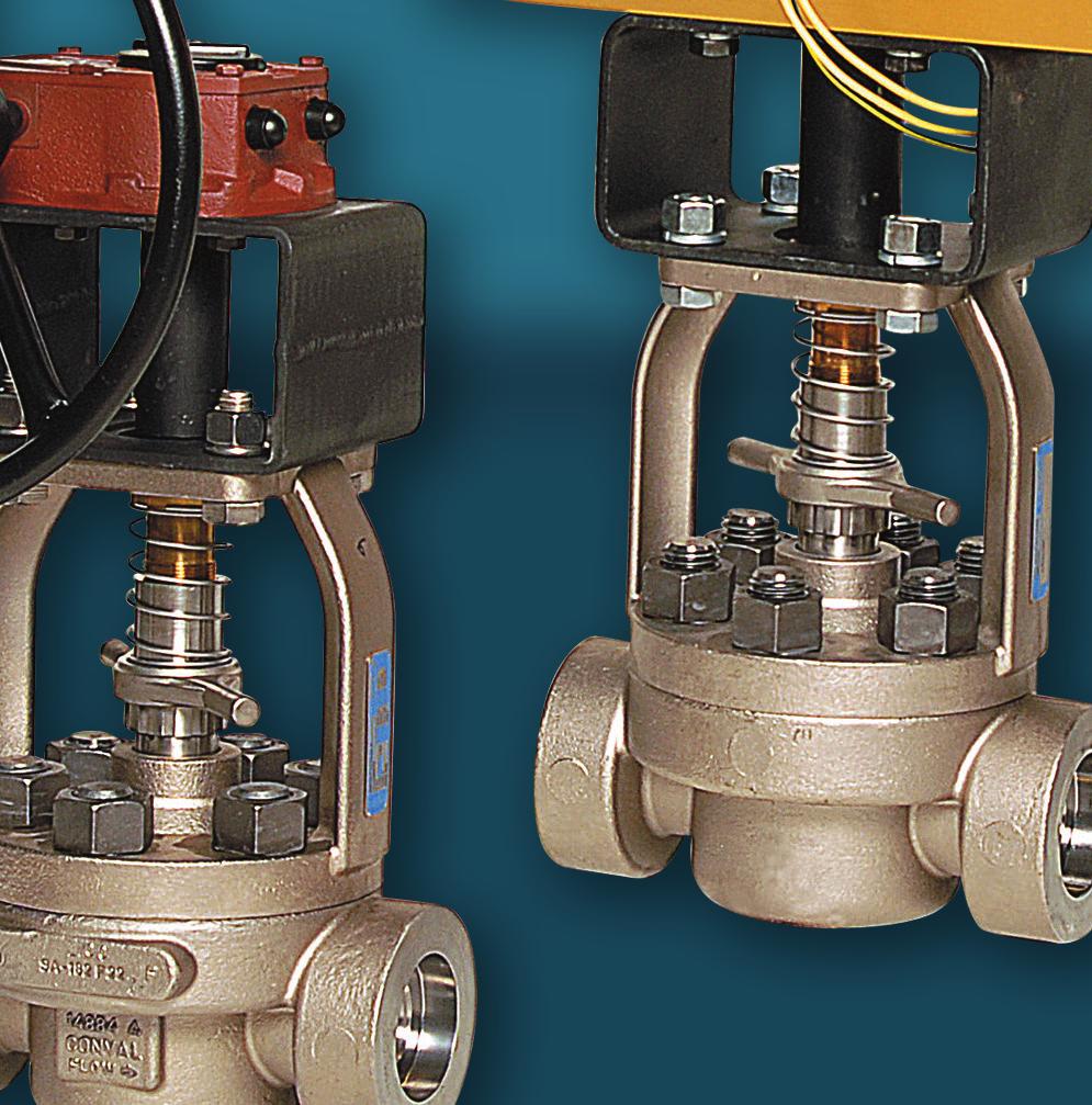
6 VI REASSEMBLY 1. Clean the bonnet seal sealing surfaces of both the body and the bonnet with Scotchbrite or similar cloth to remove any dirt or imperfections. For valves which have a laminate seal, it may be necessary to remove any remnants of the seal which may have bonded to the surfaces using a plastic knife or scraper. Examine these surfaces and make certain there is no damage that could affect the sealing of the valve. Place the new seal ring in the seal groove in the body. 2. Position the stem in the open position, with the upper stem flats in line with the pipe line. (This will assure that the stem will line up with the ball slot, as the ball is assembled in the closed position in the cartridge by the factory.) Place the bonnet assembly (bonnet, stem, gland) onto the body making certain that the stem properly engages the ball slot and that the centering ring (some actuated valves do not have a centering ring, skip this step if no centering ring is supplied) on the bonnet is aligned with the body. 3. Lubricate the studs and nuts with Never-Seez or a similar high temperature antigalling lubricant. Replace the nuts and tighten them by hand to snug the bonnet down in place. Gradually tighten the nuts one nut at a time following a diagonal pattern. Tighten the nuts to the torque values shown in Figure 4 (always be sure at least one thread is showing above the every nut when they are tight). 4. Replace the handle on the stem and tighten the handle retaining screw. VII ACTUATOR SIZING AND MOUNTING INSTRUCTIONS General Actuator Mounting Notes 1. Please consult the factory when sizing actuators. Pressures and temperatures influence the actuator sizing and stand-off height required. Figure 5 shows the torque requirements for the various Camseal size codes. 2. If you have purchased a Conval ball valve as a manual valve and plan on automating the valve please make note of the guidelines in Figure 5A,B. 3. Only quarter turn actuators may be used with the Camseal ball valve. 4. Take care when mounting the actuator to the ball valve. Some applications require high torques and large actuators. In applications below 150 F, the actuator can be direct mounted. If a mounting bracket is required be certain that the mounting bracket is sufficient to support the weight of the actuator and remain rigid, stable and properly aligned under all operating conditions. 5. Be sure there is a slight vertical gap of approximately to between the actuator coupling and the actuator shaft. This gap will compensate for tolerances of the assembly and also allow slight movement due to thermal growth of individual components. 6
7 6. Alignment between the actuator, the stand-off, coupling and the valve is critical. Any off-center loading can create considerably high torques on the valve and cause premature wear of the internal components of the valve. 7. Set the actuator stops so that the actuator travels to both the fully open or fully closed positions. The setting of the actuator stops is very important. The actuator stops will provide the only rotation limits of the valve assembly, so it is critical that the actuator be set to provide a full and proper 0 and 90 degree positioning of the ball. This will require slight over-travel of the actuator at each end of travel, resulting in total actuator travel slightly more than 90 degrees. Mounting Procedure CAUTION: If removing an actuator which has been mounted at the factory for any reason, it is recommended that the precise positon of the actuator-to-bracket and bracket-to-bonnet location be MATCH MARKED to ensure the correct position of the stem and ball upon reassembly. IF NOT, the actuator will have to be CYCLED and the correct CLOSED and OPEN position of the stem (See Figure 1D) must be verified by adjustment of the actuator stops. 1. Remove the external position stops from the bonnet of the valve by unscrewing them from the top of the bonnet assembly. 2. Before mounting the operator to the valve, be certain the valve is in the closed position. 3. If direct mounting the actuator, insert the actuator coupling onto the end of the stem. The bottom of the coupling should be flush with the top of the valve stem. Tighten the set screw until it makes contact with the flat on the double D or square of the stem. In general when the valve is open the flats of the double- D end of the stem will be parallel with the pipeline axis, stems with a single keyway will be perpendicular to the pipeline axis, and stems with a square drive will have a mark perpendicular to the pipe axis. HOWEVER, to be the most accurate and ensure shutoff it is always recommended to match up the stem valve-closed markings to the bushing as depicted in Figure 1D. 4. If the valve/actuator combination requires a stand-off, place the stand-off on the valve mounting flange. Orient the stand-off to align properly with the bolt circle of the valve flange. Bolt the two components together. Insert the coupler as in step 10 above. 5. Place the actuator on the valve (direct mount) or on the top of the bracket, making sure that the actuator is oriented in the closed position. 6. The coupling should engage the mating shaft of the actuator, leaving a to inch gap between the top of the coupling and the bottom of the mating shaft. This gap is essential to ensure proper assembly and operation of the valve/actuator unit. 7
8 7. Bolt the actuator to the valve or stand-off making sure that the axes of the actuator output shaft and the coupler are very accurately aligned with the axes of the ball valve stem. Failure to properly align the assembly will result in valve stem leakage, potential damage to other portions of the valve assembly, and possible system shut down. 8. Verify that the actuator stops have been set so that the valve is operated to the fully open and fully closed positions. 9. Actuators can be direct mounted to the ISO pattern on the mounting pad of the Camseal for process temperatures up to 150 F. Stand-offs are required on process temperatures over 150 F to assure that the actuator is not damaged by excessive heat from the pipe line. Stand-off heights should be a minimum of 6 inches for the number 5 Camseal, and 4 inches for the number 7 and 9 valves. 8

9 Figure 1 A Valve Assembly 9
10 Figure 1 B List of Items and Materials LIST OF MATERIALS FOR 1700# AND 3100# VALVES NO. NAME QTY MATERIALS 1 BODY 1 ASME SA-105 ASME SA-182 F22 ASME SA-182 F91 ASME SA-182 F316 2 BONNET ASSEMBLY 1 SEE MATERIALS BELOW 2A BONNET 1 ASME SA-216 Gr WCB ASME SA-217 Gr WC9 ASME SA-217 Gr C12A ASME SA-351 Gr CF3M 2B BONNET STEM BEARING**** 1 ASME SA-479 TYPE 410 ASME SA-479 TYPE 410 ASME SA-479 TYPE 410 AMS 5387 STELLITE #6 3 HANDLE* 1 ASME SA-216 Gr WCB 4 STEM** 1 ASTM A582 TYPE 416 ASME SB637 UNS N07718 ASME SB637 UNS N07718 ASME SB637 UNS N BUSHING 1 ASME SB150 ALUMINUM BRONZE 6 IGW SPRING 1 MFR STANDARD STAINLESS 7 GLAND 1 ASTM A582 TYPE 416 ASTM A582 TYPE 416 ASTM A582 TYPE 416 ASME SA-479 TYPE INTEGRAL GLAND WRENCH (IGW) 1 MFR STANDARD STAINLESS 9 BODY STUD* SD ASME SA193 Gr B16 ASME SA193 Gr B16 ASME SA193 Gr B16 ASME SA193 Gr B8M 10 BODY FLANGE NUT* SD ASME SA194 Gr 4 ASME SA194 Gr 4 ASME SA194 Gr 4 ASME SA194 Gr 8M 11 PACKING SET 1 BRAIDED & DIE-MOLDED FLEXIBLE GRAPHITE 12 PACKING SPACER 1 ASME SA-479 UNS S21800 (NITRONIC 60) 13 BODY/BONNET SEAL*** SST/FLEXIBLE GRAPHITE LAMINATE 14 CARTRIDGE ASSEMBLY 1 SEE MATERIALS BELOW 14A CARTRIDGE 1 ASME SA-479 TYPE 410 ASME SA-479 TYPE 410 ASME SA-479 TYPE 410 ASME SA-479 TYPE B COATED SEAT 1 ASME SB637 UNS N07718 / CHROME CARBIDE 14C COATED BALL 1 ASME SB637 UNS N07718 / CHROME CARBIDE 14D UPSTREAM SEAT 1 ASME SA-479 TYPE 410 ASME SA-479 TYPE 410 ASME SA-479 TYPE 410 AMS 5387 STELLITE #6 14E UPSTREAM SEAT BELLEVILLE 1 ASME SB637 UNS N SEAT/BODY SEAL (C-RING) 1 ASTM B670 PLATED 16 CAM 1 ASME SA-479 TYPE 410 ASME SA-479 TYPE 410 ASME SA-479 TYPE 410 ASME SA-479 UNS S SPACER 1 18 CAM BELLEVILLE 1 19 STOP BOLT* 1 20 STOP NUT* 1 21 STOP LOCK WASHER* 1 22 HANDLE NUT* 1 23 HANDLE BOLT* 1 24 SNAP RING STEM RETAINER* 1 NOTES: * SD = SIZE DEPENDENT ** FOR 4500#, STEM IS ASME SB637 UNS N07718 (INCONEL 718) *** FOR 4500#, BODY/BONNET SEAL IS ASTM B670 PLATED *** FOR 4500#, STEM BUSHING IS AMS 5387 STELLITE #6. ASME SB637 UNS N07718 ASME SB637 UNS N07718 MFR STANDARD STAINLESS MFR STANDARD STAINLESS MFR STANDARD STAINLESS MFR STANDARD CARBON STEEL MFR STANDARD ALLOY STEEL MFR STANDARD 10


11 Figure 1 C Detail of Cartridge and Cam Assembly Figure 1 D Stem Position Indication in Bushings 11
12 Figure 2 REQUIRED TORQUE (FT-LBS) VALVE SIZE CODE GLAND 5E 37 7E 37 7H 47 9H 47 9J 180 9K N 340 Figure 3 CAM SOCKET WRENCH REQUIREMENTS VALVE SIZE CODE CAM HEX DIMENSION 5E 3/8" 7E 3/8" 7H 7/16" 9H 7/16" 9J 7/16" 9K 7/16" 10N 9/16" Figure 4 REQUIRED TORQUE (FT-LBS) VALVE SIZE CODE BONNET NUT 5E 330 7E 500 7H 500 9H 500 9J 500 9K N
13 Figure 5A - Camseal Torques (to 3100#) Torque ft-lb Camseal Class 600#, 900#, 1700# & 3100# Torque Chart 5E 3100# Pressure psi 7H 3100# 11N 1700# & 12N 3100# 5E 3100# 5F/7F 3100# 8K/9K 1700# 5H/6H 1700# 9J 3100# 9L/10L/11L 10N 600# 12P 1700# 13
14 Figure 5B - Camseal Torques (4500#) Camseal Class 4500# Torque Chart Torque ft-lb Pressure psi 6E/7E 4500# 9H 4500# 10J 4500# 12L 4500# 14
15 VIII-A Camseal Body/Bonnet Seal Surface Refurbishment Instructions for Valves Equipped with C-Seals [Class 4500# or as designated] Note: The tool numbers referenced in the following steps are for the size 5E (beginning with C-242). Tools for other sizes are available and start with the prefixes as follows: Size Tool # Size Tool # Size Tool # 5E C-242 7H C-245 9J C-247 7E C-244 9H C Disassemble the bonnet from body and remove the cartridge assembly as described in section IV of these instructions. 2. Observe the C-seal groove in the body for potential damage. Take a measurement with a depth micrometer from the face of the valve to the C-seal groove. It should be to all the way around with a maximum variance of Note this measurement in 4 places. 3. The seal groove potential damage may have a cut in the surface that looks like wire draw, the cut could be to deep. The seal groove may have minor imperfections to a maximum depth of Please refer to drawing C-242 (See Figure 6A) for all parts. 5. A body seal groove with a wire cut will require the use of the C-242-E C abrasive, red/orange paper. Stick the abrasive to the C-242-C black oxide steel disc (See Figure 6C). Note: be sure to remove any sanding abrasives still on the disc C-242-C. 6. Place the disc C-242-C with the abrasive side against the C-seal groove. Place the drill arbor assembly C-242-D onto the disc C-242-C. Locate the housing assembly P/N C-242- F over the arbor assembly C-242-D and two of the 7/8-14 studs on the body assembly. Lock the housing in place with two 7/8-14 hex nuts. 7. Take measurements using the Depth Mic measuring locations on the housing. Ensure that the Sanding disc P/N C-242-C is properly seated in the seal groove. 8. Attach a ½ chuck screw gun to the arbor assembly P/N C-242-D. Apply light pressure (5-10 lbs) as you operate the screw gun at its max RPM. Run the screw gun for about 30 to 45 seconds. This should remove to of material. 9. Remove the screw gun from the arbor. Remove the 7/8-14 nuts and carefully remove the housing assembly C-242-F and arbor assembly C-242-D from the body. Remove the disc P/N C-242-C from the body. 10. Blow or vacuum out any debris caused during the sanding operation. Visually examine the location of the wire draw. Depending on the depth of the cut, it may require a little more time with the C-242-E C. If the cut looks minor at this point go to the next step. 11. Repeat steps 5 through 10 using the C-242-E abrasive paper. This will create a phonographic surface finish that is between 63 µin Ra and 32 µin Ra. Running time should be 30 seconds to 1 minute. Clean the body. Depending on the appearance of the groove this step may need to be repeated. 12. Repeat steps 5 through 10 using the C-242-E abrasive paper. This will create a smoother circular lay surface finish that is between 32 µin Ra and a 16 µin Ra. Running time should be 30 seconds to 1 minute. Clean the body. Depending on the appearance of the groove this step may need to be repeated. Measure the final depth of the C-seal groove. 15

16 13. If the final depth of the groove exceeds 0.135, the C- seal will not hold pressure and the body will require replacement. 14. Clean the components of the valve. Be sure to use a new C-seal for the body to seat surface and a new C-seal for the body to bonnet surface. Also a new bonnet assembly may be required to ensure that the mating surface of the C-Seal is in new condition. 15. Continue with reassembly of the valve in accordance with the procedures in Section IV. VIII-B Camseal Body/Bonnet Seal Surface Refurbishment Instructions for Valves Equipped with Graphite/SST Laminate Seals [Class 3100# or lower] Note: Valves 4500# or above use C-Seals, but all Class 3100# and below valves shall be retrofit with laminate seals per these instructions 1. Disassemble the bonnet from body and remove the cartridge assembly as described in section IV of these instructions. 2. For valves which have been in service whose critical body or bonnet surfaces have been corroded, worn or eroded to the point where surface refurbishment for the use of a replacement C- seal is not possible a graphite laminate body/bonnet seal can be used in its place. 3. However; replacement laminate seals cannot be used with a mirror-smooth or polished finish and should have an optimum finish of 32 to 63-microinch AARH with either a concentric lay or serrated/phonographic finish. 3.a. The sealing surfaces can be hand-worked using sandpaper of specific grits to achieve the desired finish. 3.b. OR, using an arbor or lapping tool (C-242-C or C-242-G) with self-adhesive sandpaper to roughen the surfaces of the body and bonnet while applying a circular lay pattern. Refurbishment procedure for the use of laminate seals: 4. For parts that have been in service CLEAN all corrosion, rust and scale from the critical sealing surfaces of the body and bonnet using SCOTCH-BRITE or equivalent abrasive pads. 5. INSPECT the cleaned surfaces of the body and bonnet to ensure there are no excessive pits, cracks, chipped plating or other damage that would cause leakage across the critical seal contact faces (see Figure 7 below): Figure 7 Inspection of the Sealing Surfaces and Acceptable Defects 16

17 6. Increase the surface roughness of both the body and bonnet critical sealing surfaces by SANDING using 120-grit sandpaper or rougher as needed using the following methods: 6.a. BY HAND using moderate hand pressure, fold a piece of sandpaper sheet and form into approximate circular contour of the surface and sand in a CONCENTRIC fashion with a slight back-and-forth motion repeatedly around the circumference until the desired roughness is reached (See Figure 8 below). 6.b. Using a POLISHING TOOL / ARBOR using adhesive-backed sandpaper (Ref: Tool C-242- E C for 5E) attached to a polishing tool or arbor (as suggested in Figure 8), and apply the arbor to the sealing surfaces using MODERATE PRESSURE at LOW RPM, frequently brushing or blowing off surfaces until the desired roughness is achieved. Figure 8 Sanding methods for Laminate Seal preparation 7. CLEANLINESS clean surfaces with a mild degreaser and lint-free cloths to remove any grease or residue, or any loose grit from sandpaper before attempting to install the laminate seals. 8. FINAL INSPECTION use a fingernail to verify that a rougher surface with a concentric lay has been created by the sanding operation. Use a roughness height comparison block, or visual comparison to verify approximate roughness height to ensure it is within specification. 9. FINAL ASSEMBLY AND VERIFICATION 9.a. Prior to assembly, inspect the replacement laminate seals and ensure their top and bottom surfaces have not been damage, cut or dented during shipment or handling. Deep dents, cuts or abrasions will adversely affect sealing performance. 9.b. Reassemble the valve in accordance with the procedures of Section IV. It is recommended that a SYSTEM PROOF TEST be performed if a full hydrostatic test of the valve assembly is not possible to ensure the new seal in the assembly is ready for service. 17
18 Figure 6A Body/Bonnet C-Seal Groove Resurfacing Tool (5E shown) Figure 6B Body/Bonnet C-Seal Groove Resurfacing Tool (5E shown) 18
19 Figure 6C Body/Bonnet C-Seal Groove Resurfacing Arbor Tools (5E shown) 19

20 World Headquarters: 265 Field Road P.O. Box 1049, Somers, CT USA Phone (860) Fax (860) Conval s policy is one of continuous development and improvement. Every effort is made to produce up-to-date literature but this catalog should not be regarded as an infallible guide to current specifications and does not form part of any contract. Conval reserves the right to make product improvements and changes without prior notice. Form CamsealServicing2017-KIT Printed in USA High performance valves and accessories for the world s most demanding applications. 2
Clampseal. Globe Valve Servicing Instructions
 Clampseal Globe Valve Servicing Instructions 2 CLAMPSEAL valves have unique features which enable them to be completely serviced in line. The following service operations are possible: Seat Refacing Disc
World Class Camseal Metal-Seated Ball Valves
 World Class Camseal Metal-Seated Ball Valves Unique Zero Leakage Design Top Quality Manufacturing Long, Reliable Life Cycle Top Entry Design for In-Line Maintenance & Repair Enormous Savings in Labor,
MEMORY SEAL BALL VALVES MAINTENANCE MANUAL 2 12, Class 150 & 300, Regular Port, Flanged Unibody
 MEMORY SEAL BALL VALVES MAINTENANCE MANUAL 2 12, Class 150 & 300, Regular Port, Flanged Unibody I INTRODUCTION These rugged, versatile, high performance, regular port, ball valves meet all requirements
IOM Manual. IOM Manual. Series 76/77.
 IOM Manual IOM Manual Series 76/77 www.flowlinevalves.com Flow Line Valve and Controls, L.L.C. 110 Main Project Road Schriever, LA 70395 P.O. Box 677 Schriever, LA 70395 Phone 985-414-6004 * Toll Free
PFA LINED BALL VALVES Installation, Operation and Maintenance Manual
 ACRIS PFA LINED BALL VALVES WWW.AMRESIST.COM Table of Contents Safety Instructions - Definition of Terms............................................2 Introduction..............................................................2
World Class Clampseal Throttling Valves. Replaceable Seat/Venturi Low Velocity Across Main Seat Precise Flow Control Pressure Seal Bonnet
 World Class Clampseal Throttling Valves Replaceable Seat/Venturi Low Velocity Across Main Seat Precise Flow Control Pressure Seal Bonnet Conval Clampseal Throttling Valves are designed for a wide range
Installation, Operation and Maintenance Guide II NIBCO High Performance Butterfly Valves Series 6822 and 7822
 Installation, Operation and Maintenance Guide II NIBCO High Performance Butterfly Valves Series 6822 and 7822 Statements: NIBCO High Performance Butterfly Valves, Series 6822 and 7822, have been designed
INSTALLATION - MAINTENANCE MANUAL Severe Service Series M4 Ball Valve
 INSTALLATION - MAINTENANCE MANUAL Severe Service Series M4 Ball Valve Date: May 2016/ Page 2 of 12 Table of Contents 1. Safety Information - Definition of Terms..........................2 2. Bill of Materials....................................
INSTALLATION & MAINTENANCE MANUAL
 INSTALLATION & MAINTENANCE MANUAL 3-WAY/4-WAY/5-WAY MULTI-PORT BALL VALVES T TEFLON PARTS - 1. Seat x 5 pcs. 2. Joint Gasket x 5 pcs. 3. Retainer Seal x 5 pcs. 4. Thrust Washer x 1 pc. 5. O-Ring x 1 pc
Scope. Applicability. Caution. I & M CV3000 Series. Storage. Installation & Maintenance Instructions for Marwin CV3000 Series Three Piece Ball Valves
 I & M CV3000 Series 3170 Wasson Road Cincinnati, OH 45209 USA Phone 513-533-5600 Fax 513-871-0105 marwin@richardsind.com www.marwinvalve.com Installation & Maintenance Instructions for Marwin CV3000 Series
McCannalok HIGH PERFORMANCE BUTTERFLY VALVE OPERATION AND MAINTENANCE MANUAL. The High Performance Company
 McCannalok HIGH PERFORMANCE BUTTERFLY VALVE OPERATION AND MAINTENANCE MANUAL The High Performance Company Table of Contents Safety Information - Definition of Terms... 1 Introduction... 1 Installation...
INSTALLATION, OPERATION, MAINTENANCE MANUAL FOR MANUALLY OPERATED STOP CHECK VALVE
 INSTALLATION, OPERATION, MAINTENANCE MANUAL FOR MANUALLY OPERATED STOP CHECK VALVE Page 1 of 13 1.1 General CHAPTER 1 - GENERAL INFORMATION This manual contains maintenance instructions with pertinent
Table of Contents Visual Inspection and Neutralizing... 3 Disassembly
 1 Table of Contents Visual Inspection and Neutralizing... 3 Disassembly... 3... 4... 4 Cleaning... 4 Inspection... 4 Reconditioning of Valve Seats... 5 Lapping Procedures... 5 Lapping Blocks... 5 Lapping
Flow Line Controls. Installation & Operations Manual SERIES 20/21 Pneumatic Actuators
 Flow Line Controls Installation & Operations Manual SERIES 20/21 Pneumatic Actuators Flow Line Controls, Inc. P.O. Box 677 Schriever, LA 70395 Phone: 985-414-6003 Toll Free 1-800-815-9226 Fax 985-414-6072
for ½" thru 2" 800 lb. Piston Lift Check Valves with Resilient Seat Option
 Manual No. 800-PC Issued: March 31, 2004 INSTRUCTION MANUAL for ½" thru 2" 800 lb. Piston Lift Check Valves with Resilient Seat Option Flowserve Corporation Flow Control Division 1900 S. Saunders Street
Bray/McCannalok High Performance Butterfly Valve Operation and Maintenance Manual
 Bray/McCannalok High Performance Butterfly Valve Operation and Maintenance Manual Table of Contents Definition of Terms 1 Introduction 1 Installation 1 Maintenance 2 Stem Seal Replacement 4 Seat Replacement
FLOWSERVE CORPORATION NOBLE ALLOY VALVE BALL VALVE REPAIR INSTRUCTION
 FLOWSERVE CORPORATION NOBLE ALLOY VALVE BALL VALVE REPAIR INSTRUCTION Cookeville Valve Operation 1978 Foreman Drive Cookeville, TN 38541 PH: 800-251-6761 931-432-4021 FAX: 931-432-5518 CONTENTS FLOWSERVE/NOBLE
SWING CHECK VALVES SERIES 52-SC SERIES 600
 SWING CHECK VALVES SERIES 52-SC SERIES 600 FEATURES/BENEFITS/SPECIFICATIONS AMERICAN Flow Control Series 52-SC Swing Check Valves incorporate design features to help increase service life for water and
[DRAFT VERSION] For use for company in Europe who will place the product on the market. Please amend which necessary. Document No:
![[DRAFT VERSION] For use for company in Europe who will place the product on the market. Please amend which necessary. Document No:](/thumbs/87/96489423.jpg "[DRAFT VERSION] For use for company in Europe who will place the product on the market. Please amend which necessary. Document No:") Three-Piece ball valve EA-307 Series PED Category I, II EA-307 User Manual English Version [DRAFT VERSION] For use for company in Europe who will place the product on the market. Please amend which necessary.
Three-Piece ball valve EA-307 Series PED Category I, II EA-307 User Manual English Version [DRAFT VERSION] For use for company in Europe who will place the product on the market. Please amend which necessary.
Power-Seal High Performance Butterfly Valve: Series P1 Installation & Maintenance Manual
 CAUTION: 1. For your safety read this manual completely before installation or servicing. 2. Before installing or servicing, please ensure the line pressure has been relieved, and any hazardous fluids
INSTRUCTION MANUAL. Anchor Darling 1878 Swing Check Valves. Installation Operation Maintenance. Sizes 1/2 through 2 FCD ADENIM
 INSTRUCTION MANUAL Anchor Darling 1878 Swing Check Valves Sizes 1/2 through 2 Installation Operation Maintenance FCD ADENIM0006-00 Table of Contents 1.0 Physical Description and Operation of Equipment
When installing the screwed end, socket weld & flanged end valves the following respective procedures shall be followed for better performance.
 1. Storage LARSEN & TOUBRO LIMITED Page 1 of 5 1.1. All valves are to be stored in fully open position, in order to protect the sphere surface and soft valve seats. 1.2. Before shipping, the inlet and
YARWAY HANCOCK Y-PATTERN FORGED STEEL GLOBE STOP VALVES SERIES 4000
 Direct contact and metal-to-metal seating make this Y-pattern globe stop valve ideal for most shut-off applications. FEATURES All valves feature integral Stellite hardfacing on both body and disc seating
Operating & Maintenance Manual For Steam Conditioning Valve
 For Steam Conditioning Valve 1 Table of Contents 1.0 Introduction 3 2.0 Product description 3 3.0 Safety Instruction 4 4.0 Installation and Commissioning 5 5.0 Valve Disassembly 6 6.0 Maintenance 6 7.0
REACTOR DISCHARGE VALVES S & DIGESTER BLOW VALVES SB & 5300SB B FLANGED BALL VALVES
 REACTOR DISCHARGE VALVES 8-12 530S & 5300 6-10 6300 DIGESTER BLOW VALVES 8-12 530SB & 5300SB 6-10 6300B FLANGED BALL VALVES Installation, Maintenance and Operating Instructions IMO-295 EN 11/2017 2 IMO-302
Apollo Standard Port, Full Port & One Piece Flanged Ball Valves Installation, Operation, & Maintenance Guide
 I854000.F M16005 Apollo Standard Port, Full Port & One Piece Flanged Ball Valves Introduction This manual presents guidelines for the Installation, Operation and Maintenance of manual and automated Apollo
V-SEGMENT SERIES V-Port Segment Control Valves (VS/VV/VM) Installation & Maintenance Manual
 Installation & Maintenance Manual") CAUTION: 1. For your safety read this manual before installation or servicing. 2. Before installing or servicing, please ensure the line pressure has been relieved, and any hazardous fluids have been drained
CAUTION: 1. For your safety read this manual before installation or servicing. 2. Before installing or servicing, please ensure the line pressure has been relieved, and any hazardous fluids have been drained
MODEL 5540 CONTENTS. Installation, Operation and Maintenance Instructions 1.0 GENERAL
 Installation, Operation and Maintenance Instructions MODEL 5540 Sep 20 CONTENTS.0 GENERAL. Model Number---------------------------------------------------------------------------------------------------------------
SERIES 90/91 R PNEUMATIC ACTUATOR OPERATION AND MAINTENANCE MANUAL. The High Performance Company
 SERIES 90/91 R PNEUMATIC ACTUATOR OPERATION AND MAINTENANCE MANUAL The High Performance Company Table of Contents Sa f e t y Information - Definition o f Te r m s... 1 De s c r i p t i o n o f Op e r at
Fisher TBX Hydro Plug Fixture
 Instruction Manual TBX Hydro-Plug Fixture Fisher TBX Hydro Plug Fixture Contents Introduction... 1 Scope of Manual... 1 Description... 2 Educational Services... 2 Principle of Operation... 2 Maintenance...
AV INSTALLATION, OPERATION & MAINTENANCE MANUAL
 Rack & Pinion Pneumatic Actuators AV INSTALLATION, OPERATION & MAINTENANCE MANUAL AVCS PO Box 68172 Minneapolis, MN 55418 TABLE OF CONTENTS CHAPTER 1: PRODUCT DESCRIPTION 3 CHAPTER 2: TECHNICAL FEATURES
2.- HANDLING OF VALVES BEFORE ASSEMBLY 3.- FITTING THE VALVE TO THE REST OF THE ASSEMBLY 5.- PERIODICAL INSPECTION OF THE VALVE AND MAINTENANCE
 Page 1 of 16 CONTENTS 1.- INTRODUCTION 2.- HANDLING OF VALVES BEFORE ASSEMBLY 3.- FITTING THE VALVE TO THE REST OF THE ASSEMBLY 4.- OPERATION OF A BALL VALVE 5.- PERIODICAL INSPECTION OF THE VALVE AND
Baumann Way Control Valve
 Instruction Manual 24003 Valve Baumann 24003 3-Way Control Valve Contents Introduction... 1 Scope of Manual... 1 Safety Precautions... 2 Educational Services... 3 Maintenance... 3 Installation... 3 Air
Baumann 24000F Wafer Control Valve
 Instruction Manual 24000F Valves Baumann 24000F Wafer Control Valve Contents Introduction... 1 Scope of Manual... 1 Safety Precautions... 2 Maintenance... 2 Installation... 3 Air Piping... 3 Disassembly...
butterfly valves high performance TRIPLE OFFSET HP-TRI REV0
 high performance EXECUTION 1st OFFSET 2nd OFFSET 3rd OFFSET The BELVEN-TRI series incorporate triple offset disc configuration. With this configuration the disc seal makes contact with body seat, only
MK Series - High Performance Butterfly Valves Operation and Maintenance Instructions
 COMMERCIAL Bray Controls Commercial Division 13788 West Road, Suite 200A Houston, Texas 77041 BCDSales@Bray.com Phone: 1-888-412-2729 Fax: 1-888-412-2720 www.braycommercialdivision.com MK Series - High
Vickers. Overhaul Manual. Vane Pumps. Small and Large Series Combination Pumps VC(K)(S)-**-(*)*D*-6(1) VC(K)(S)-**-(*)-*-*D*-5(1)
(S)-**-(*)*D*-6(1) VC(K)(S)-**-(*)-*-*D*-5(1)") Overhaul Manual Vickers Vane Pumps Small and Large Series Combination Pumps VC(K)(S)-**-(*)*D*-6(1) VC(K)(S)-**-(*)-*-*D*-5(1) Revised 12/1/86 I-3150-S Table of Contents Section I. Introduction................................................................................
Overhaul Manual Vickers Vane Pumps Small and Large Series Combination Pumps VC(K)(S)-**-(*)*D*-6(1) VC(K)(S)-**-(*)-*-*D*-5(1) Revised 12/1/86 I-3150-S Table of Contents Section I. Introduction................................................................................
I & M Mark 708ME. Ideal Installation. Start-Up Procedure. Installation & Maintenance Instructions for Mark 708 & Motor Actuator
 I & M Mark 708ME 3170 Wasson Road Cincinnati, OH 45209 USA Phone 513-533-5600 Fax 513-871-0105 info@richardsind.com www.lowfl owvalve.com Installation & Maintenance Instructions for Mark 708 & Motor Actuator
TBV OPERATION AND MAINTENANCE MANUAL SERIES 1800: FLANGED BALL VALVE. For technical questions, please contact the following:
 TBV OPERATION AND MAINTENANCE MANUAL SERIES 1800: FLANGED BALL VALVE For technical questions, please contact the following: Engineering Department 1537 Grafton Road Millbury, MA 01527 Phone: (508) 887-9400
A. This Section includes general duty valves common to several HVAC piping systems.
 SECTION 23 05 23 - PART 1 - GENERAL 1.1 RELATED DOCUMENTS A. Drawings and general provisions of the Contract, including General and Supplementary Conditions and Division 01 Specification Sections, apply
250L Cartridge Dual Seal
 INSTALLATION, OPERATION AND MAINTENANCE INSTRUCTIONS 250L Cartridge Dual Seal Installation, Operation and Maintenance Instructions TABLE OF CONTENTS 1.0 Cautions...2 2.0 Transport and Storage...2 3.0 Description...2
IOM Manual. IOM Manual. Series 20/21.
 IOM Manual IOM Manual Series 20/21 www.flowlinevalves.com Flow Line Valve and Controls, L.L.C. 110 Main Project Road Schriever, LA 70395 P.O. Box 677 Schriever, LA 70395 Phone 985-414-6004 * Toll Free
Series Direct contact and metal-to-metal seating makes the T-pattern globe stop valve ideal for most shut-off applications.
 7 YARWAY Hancock T-Pattern Globe valves Direct contact and metal-to-metal seating makes the T-pattern globe stop valve ideal for most shut-off applications Features Heavy integral stellite hardfacing on
Fisher 657 Diaphragm Actuator Sizes and 87
 Instruction Manual 657 Actuator (30-70 and 87) Fisher 657 Diaphragm Actuator Sizes 30 70 and 87 Contents Introduction... 1 Scope of Manual... 1 Description... 2 Specifications... 2 Installation... 3 Mounting
Boston Gear ORC Series
 Boston Gear ORC Series Trig-O-Matic Overload Release Clutches Installation and Maintenance Instructions Doc. No. ORC Series Model S www.bostongear.com ORC SERIES TRIG-O-MATIC OVERLOAD RELEASE CLUTCHES
Delayed Coker Switch Ball Valve
 Delayed Coker Switch Ball Valve Series Y4 8-16 Installation, Maintenance and Operating Instructions 1 Y4 70 EN 11/2017 2 1 Y4 70 EN TABLE OF CONTENTS 1. GENERAL... 3 1.1 Safety Precautions... 3 1.2 Valve
Fisher ENVIRO SEAL Packing System for Rotary Valves
 D0X0 July 07 Fisher ENVIRO SEAL Packing System for Rotary Valves Contents Introduction... Scope of Manual... Valve/Actuator Shaft Coupler... Description... Installation... Removing the Actuator... Installing
HYDRAULICS. TX420 & & lower. Hydraulic Tandem Pump Removal. 4. Remove the LH side panel (Fig. 0388).
.") TX420 & 425 240000299 & lower 4. Remove the LH side panel (Fig. 0388). Hydraulic Tandem Pump Removal Note: Cleanliness is a key factor in a successful repair of any hydraulic system. Thoroughly clean all
TX420 & 425 240000299 & lower 4. Remove the LH side panel (Fig. 0388). Hydraulic Tandem Pump Removal Note: Cleanliness is a key factor in a successful repair of any hydraulic system. Thoroughly clean all
FOR FUTURE REFERENCE SERIES 93HPS
 Hypro Series 93HPS Hydraulically Driven Wetseal Multistage Pumps Repair Manual KEEP FOR FUTURE REFERENCE Form L-1578R Rev. A SERIES 93HPS Hydraulically Driven Stainless Steel Multistage Centrifugal Pumps
BETTIS SERVICE INSTRUCTIONS DISASSEMBLY AND REASSEMBLY FOR CB-SR-S SEISMIC SPRING RETURN SERIES PNEUMATIC ACTUATORS
 BETTIS SERVICE INSTRUCTIONS DISASSEMBLY AND REASSEMBLY FOR CB-SR-S SEISMIC SPRING RETURN SERIES PNEUMATIC ACTUATORS PART NUMBER: 102264 REVISION: "C" DATE: November 2000 Page 1 of 11 1.0 INTRODUCTION 1.1
Newco / OIC / Cooper Forged Valves. Operation & Maintenance. Manual
 NEWCO / OIC / COOPER VALVES Newmans Inc., Newmans Valve Ltd. Operation & Maintenance Manual Revision 2, 9 May 2007 1. Introduction and Safety Information... 1 1.1. Introduction... 1 1.2. Safety Information...
CV Control Valves Installation and Operation Manual
 CV1500 - Control Valves Installation and Operation Manual 652-EN Overview Warning: This bulletin should be used by experienced personnel as a guide to the installation of the Armstrong CV1500 Control Valve.
Model DF269 Control Valve
 Figure 1 DF269 Control Valve TABLE OF CONTENTS Introduction 2 Fail Open Actuator Disassembly 6 General 2 Body and Packing Reassembly 7 Scope 2 Fail Closed Actuator Resassembly 8 Specifications 3 Fail Open
LOW PRESSURE BALANCED VALVE DIAPHRAGM BALANCED
 DIAPHRAGM BALANCED All Rights Reserved. All contents of this publication including illustrations are believed to be reliable. And while efforts have been made to ensure their accuracy, they are not to
OPERATION AND PARTS MANUAL
 OPERATION AND PARTS MANUAL MODEL NUMBER : PART NUMBER : GTL 1110 1900-0510 SERIAL NUMBER : BAYNE MACHINE WORKS, INC. PHONE: (864) 288-3877 910 FORK SHOALS ROAD TOLL FREE: (800) 535-2671 GREENVILLE S.C.,
Installation, Operation, and Maintenance Manual Full Port Y-Pattern, Bolted Bonnet, Globe and Check Valves
 SMITH VALVES Installation, Operation, and Maintenance Manual Full Port Y-Pattern, Bolted Bonnet, Globe and Check Valves Globe Valve Series: YG80/YG15 Welded Bonnet Globe Valve Series: YG87/YG17 Piston
Model DF233 Control Valve
 Figure 1 DF233 Control Valve TABLE OF CONTENTS Introduction 2 Body and Packing Reassembly 7 Specifications 3 Fail Closed Actuator Reassembly 8 Valve Sizes 3 Fail Open Actuator Reassembly 9 Unpacking 4
Fisher CVX Hydro Plug Fixture
 Instruction Manual CVX Hydro-Plug Fixture Fisher CVX Hydro Plug Fixture Contents Introduction... 1 Scope of Manual... 1 Description... 1 Educational Services... 2 Principle of Operation... 2 Maintenance...
GT-200 GATE VALVES PN16, Screwed end
 Document No. : MD-QO-04-281 Date : 2009/07 /17 Version : 1.0 GT-200 GATE VALVES PN16, Screwed end USER MANUAL Modentic Industrial Corporation 14F-1,No.57Taya Rd.,Taichung,Taiwan,R.O.C. Email:modentic@ms9.hinet.net
Before installation these instructions must be fully read and understood
 Before installation these instructions must be fully read and understood Yoke bushing Split gland bushing One-piece body with accessible internals Gland Swing bolts Fully retractable stellite disc Figure
Baumann 24000C Carbon Steel Little Scotty Control Valve Instructions
 Instruction Manual D103356X012 24000C Control Valve Baumann 24000C Carbon Steel Little Scotty Control Valve Instructions CONTENTS Introduction...1 Scope...1 Safety Precautions...1 Maintenance...2 Flow
Baumann Little Scotty Bronze Control Valve
 Instruction Manual 24000 Valve Baumann 24000 Little Scotty Bronze Control Valve Contents Introduction... 1 Scope of Manual... 1 Safety Precautions... 2 Maintenance... 2 Installation... 3 Air Piping...
Fisher 1051 and 1052 Style H and J Sizes 40, 60 and 70 Rotary Actuators
 Instruction Manual 1051 and 1052 H & J Actuators Fisher 1051 and 1052 Style H and J Sizes 40, 60 and 70 Rotary Actuators Contents Introduction... 1 Scope of Manual... 1 Description... 2 Specifications...
Keystone K-LOK Series 36 and 37 High Performance Butterfly Valve Installation and Operation Manual
 Before installation these instructions must be fully read and understood General Suggested installation orientation is with valve shaft horizontal or inclined from vertical. Unless otherwise recommended
INSTALLATION, OPERATION & MAINTENANCE MANUAL
 Rack & Pinion Pneumatic Actuators INSTALLATION, OPERATION & MAINTENANCE MANUAL QSM, Inc. 127 Village Lane Easley, SC 29642 U.S.A. Ph: (864) 605-0150 Fax: (864) 605-0830 www.tru-flo.com TABLE OF CONTENTS
Baumann 24000CVF Carbon & 24000SVF Stainless Steel Flanged Valve Instructions
 Instruction Manual D103360X012 24000CVF/SVF Control Valve Baumann 24000CVF Carbon & 24000SVF Stainless Steel Flanged Valve Instructions CONTENTS Introduction...1 Scope of Manual...1 Safety Precautions...1-2
MACH 1 TSQV SEVERE SERVICE PLUG VALVES
 MACH 1 TSQV SEVERE SERVICE PLUG VALVES FOREWORD The Flowserve Corporation has established this Installation, Operating and Maintenance Manual to facilitate field installation, operation and repair of Triple
FORGED HIGH PRESSURE BONNETLESS. ASME CLASSES: Sizes: 1 2 4" ( mm) U.S. Patent # Patented Easy Maintenance!
 U.S. Patent # Patented Easy Maintenance!") FORGED HIGH PRESSURE BONNETLESS ASME CLASSES: 1690 4500 Sizes: 1 2 4" (15 100 mm) U.S. Patent # 4356832 Patented Easy Maintenance! PROFILE Velan is one of the world's leading manufacturers of industrial
FORGED HIGH PRESSURE BONNETLESS ASME CLASSES: 1690 4500 Sizes: 1 2 4" (15 100 mm) U.S. Patent # 4356832 Patented Easy Maintenance! PROFILE Velan is one of the world's leading manufacturers of industrial
IMO-200EN 09/2010. Trunnion mounted forged ball valves Model FF and GG. Installation, Maintenance and Operating Instructions IMO-200EN 09/2010
 IMO-200EN 09/2010 Trunnion mounted forged ball valves Model FF and GG Installation, Maintenance and Operating Instructions IMO-200EN 09/2010 2 IMO-200EN Table of Contents I GENERAL INFORMATION...................
W-K-M Model MA-1 DynaCentric Butterfly Valve
 Page 1 of 12 W-K-M Model MA-1 DynaCentric Butterfly Valve Page 2 of 12 Published January 2003 W-K-M and DynaCentric are trademarks of Cooper Cameron Corporation Cooper Cameron Corporation, Cooper Cameron
I & M 8000 Series. Ideal Installation Schematic. Preferred Installation. Trouble Shooting
 I & M 8000 Series 3170 Wasson Road Cincinnati, OH 45209 USA Phone 513-533-5600 Fax 513-871-0105 lowflow@richardsind.com www.lowflowvalve.com Installation & Maintenance Instructions for 8000 Series Low
I-795/906. Series 795 and 906 Installation-Ready Knife Gate Valves WARNING INSTALLATION AND MAINTENANCE INSTRUCTIONS
 INSTALLATION AND MAINTENANCE INSTRUCTIONS I-795/906 Series 795 and 906 Installation-Ready Knife Gate Valves HANDWHEEL OPERATOR PNEUMATIC OPERATOR HYDRAULIC OPERATOR WARNING Read and understand all instructions
JT SERIES ANGLE STEM TANK BOTTOM BALL VALVE DN25 DN150. Installation, Maintenance and Operating Instructions
 JT SERIES ANGLE STEM TANK BOTTOM BALL VALVE DN25 DN150 Installation, Maintenance and Operating Instructions IMO-235 EN 3/2019 2 IMO-235 EN TABLE OF CONTENTS 1. GENERAL... 3 1.1 Scope of the Manual... 3
Maintenance Information
 16572679 Edition 2 May 2014 Air Drill QP Series Maintenance Information Save These Instructions Product Safety Information WARNING Failure to observe the following warnings, and to avoid these potentially
COMMERCIAL. BV & BVM Series Installation Instructions 06/29/15
 COMMERCIAL Bray Controls Commercial Division 13788 West Road, Suite 00A Houston, Texas 77041 BCDSales@Bray.com Phone: 1-888-41-79 Fax: 1-888-41-70 www.braycommercialdivision.com BV & BVM Series Installation
Boston Gear LOR Series
 Boston Gear LOR Series Trig-O-Matic Lite Overload Release Clutch Installation and Maintenance Instructions Doc. No. LOR Series Trig-O-Matic Lite www.bostongear.com LOR SERIES TRIG-O-MATIC LITE OVERLOAD
METERING VALVE 2" STEM GUIDED
 2" STEM GUIDED All Rights Reserved. All contents of this publication including illustrations are believed to be reliable. And while efforts have been made to ensure their accuracy, they are not to be construed
Electric motor testing
 Electric motor testing MOTOR (MODELS EJ4-4001 AND EJ8-4001A) 23 GENERAL INFORMATION The vehicle is equipped with a 48-volt DC, shunt-wound, reversible traction motor. The shunt-wound motor is designed
Mogas MVP Installation, Operation And Maintenance Manual
 Mogas MVP Installation, Operation And Maintenance Manual Congratulations on your purchase of a Mogas Valve For Power This pamphlet is intended to provide complete information on installation, operation,
Bray/Mckannalok Butterfly Valve Series 40/41/42/43/44/45 Installation Manual Technical Bulletin No Date: May 2004/Page 1 of 6
 Date: May 2004/Page 1 of 6 Bray/McCannalok Butterfly Valves Installation and Maintenance Instructions ANSI Classes 150 and 300 - Sizes 2-1/2 through 24 ANSI Classes 600 - Sizes 3 through 16 Bidirectional
Fig.01 Fig.02 Fig.03. Disassembly & Reassembly Instructions SBV-HP - Page 3
 M12A14 WITH FLOATING BACKSEAT 3 Fig.01 Fig.02 Fig.03 Disassembly & Reassembly Instructions SBV-HP - Page 3 M12A14 WITH FLOATING BACKSEAT 3 1. Caution, before any attempt is made to disassemble, verify
OPERATION AND PARTS MANUAL
 OPERATION AND PARTS MANUAL MODEL NUMBER : PART NUMBER : GRL 1110 1900-0540 SERIAL NUMBER : BAYNE MACHINE WORKS, INC. PHONE: 864.288.3877 910 FORK SHOALS ROAD TOLL FREE: 800.535.2671 GREENVILLE SC, 29605
SPN II. S h a r p e T o l l Free (877) F a x (708)
 F a x (708)") SPN II S h a r p e T o l l Free (877) 774-2773 F a x (708) 562-9250 www.sharpevalves.com 1 SPN II Pneumatic Actuator Rack & pinion design The standard actuator configuration has hard anodized aluminum
SPN II S h a r p e T o l l Free (877) 774-2773 F a x (708) 562-9250 www.sharpevalves.com 1 SPN II Pneumatic Actuator Rack & pinion design The standard actuator configuration has hard anodized aluminum
LOR Series Trig-O-Matic Lite Overload Release Clutch
 LOR Series Trig-O-Matic Lite Overload Release Clutch P-3029-BG LOR Series Installation and Operation An Altra Industrial Motion Company Contents I. Introduction A. Operating Principle... 3 B. Torque Adjustment...
servicing the swivel
 servicing the swivel The swivel seals and bearings require periodic replacement. This document describes how to determine which service procedure to use to service the swivel assembly, part number 101110.
Sachs 48mm Closed Cartridge fork Service Manual
 Sachs 48mm Closed Cartridge fork Service Manual 1 Fork seal driver 2 Special soft jaws 3 Fork cap wrench 4 Rebound rod holding tool 5 Compression assembly holding tool 6 Retaining clip tool Special Tools
Maintenance Information
 80234313 Edition 1 June 2006 Air Grinder, Die Grinder, Sander and Belt Sander Series G1 (Angle) Maintenance Information Save These Instructions WARNING Always wear eye protection when operating or performing
SECTION VALVES PART 1 - GENERAL
 1.01 RELATED DOCUMENTS SECTION 15100 VALVES PART 1 - GENERAL A. The work in this section includes the furnishing and installation of all control valves and accessories shown on the construction plans and
Maintenance Information
 80234313 Edition 2 May 2014 Air Grinder, Die Grinder, Sander and Belt Sander Series G1 (Angle) Maintenance Information Save These Instructions Product Safety Information WARNING Failure to observe the
5000/6000 SERIES BALL VALVES INSTALLATION - MAINTENANCE MANUAL
 Date: August 2011 / Page 1 of 6 5000/6000 SERIES BALL VALVES INSTALLATION - MAINTENANCE MANUAL DESIGN The design features three piece construction and a free floating ball allowing ease of maintenance
26 Series Stainless Steel 2-way Ball Valves
 1-800-899-0553 26 Series Stainless Steel 2-way Ball Valves Users Manual Installation, Operation, & Maintenance 1. General Precaution 1.1. Material Section Material deterioration is determined by the contained
YOUR GLOBAL FLOW CONTROL PARTNER. BRAY/MCCANNALOK EN High Performance Butterfly Valve Operation and Maintenance Manual
 YOUR GLOBAL FLOW CONTROL PARTNER BRAY/MCCANNALOK EN High Performance Butterfly Valve TABLE OF CONTENTS 1.0 Definition of Terms....................................... 2 2.0 Introduction...........................................
Series Direct contact, metal-to-metal seating, make the globe valve ideal for most shut-off applications. Features
 Direct contact, metal-to-metal seating, make the globe valve ideal for most shut-off applications. Features General application Designed for ASME boiler and pressure vessel code, section I applications
GBV-G Balancing Valves
 Ductile Iron ASTM A6, Grade 6-4-2 The Series GBV is a multi-turn, Y-style globe valve designed for accurate determination and control of fluid flow to circuits requiring precise balancing. Max. Working
Installation, Operation and Maintenance Instructions
 Installation, Operation and Maintenance Instructions MODEL 5520 June 2002 1.0 GENERAL... 2 Model Number Information... 2 Features... 3 Specifications... 4 Table 1A. Flow Coefficients (C V ), Modified Percent
INSTRUCTION MANUAL. for BUTTERFLY VALVES
 STD-BFV-MGA Revision 0 11/21/03 INSTRUCTION MANUAL for BUTTERFLY VALVES Flowserve U.S. Inc Flow Control Division 1900 South Saunders Street P.O. Box 1961 Raleigh, NC 27603 Phone: (919) 832-0525 FAX: (919)
OPERATION AND MAINTENANCE INSTRUCTIONS
 OPERATION AND MAINTENANCE INSTRUCTIONS 334 SERIES THREE-PIECE BALL VALVES 1/4 to 2-1/2 Installation and Operation Always install your valve according to accepted industry standards and practices and operate
Discount-Equipment.com
 LS40D, LS40TD, LS50TD, LS60TD LS-Series Remix Shaft Coupler Retrofit Kit Installation Instructions The following instructions are intended to assist the user in the installtion of the LS-Series Remix Shaft
DelTorq Series 21 ACTUATOR
 Jamieson Equipment Company DelTorq Series 21 ACTUATOR INSTALLATION, OPERATION AND MAINTENANCE MANUAL ENGINEERING DATA SHEET E.D.S. NO EDS055 ISSUE DATE - -- 20/01/2007 (Please read the entire instructions
Installation & Maintenance Manual SPRING ENGAGED FRICTION CLUTCHES THROUGH SHAFT MOUNT - BALL BEARING PILOT REGULAR DUTY
 Installation & Maintenance Manual SPRING ENGAGED FRICTION CLUTCHES THROUGH SHAFT MOUNT - BALL BEARING PILOT REGULAR DUTY Catalog Products: E3A2R-STH E4A2R-STH E5A2R-STH E6A2G-STH And non-catalog variations