Arctic Equipment Manufacturing Corporation M3500V Hydraulic Power Unit. Table of Contents
|
|
|
- Austin McDaniel
- 6 years ago
- Views:
Transcription
1 Arctic Equipment Manufacturing Corporation M3500V Hydraulic Power Unit Table of Contents General Information...2 Hydraulic Operational Diagrams...8 Hydraulic & Electrical Installation...19 Parts List...26 Troubleshooting...29


2 Arctic Equipment Manufacturing Corporation M3500V Power Unit R03 M3500V Operating Information
3 Arctic Equipment Manufacturing Corporation M3500V Power Unit R03 Warranty Identification General Information about Power Unit M3500V For purposes of warranty consideration, recording the serial number of the power unit is necessary. This serial number is displayed on a reservoir of the power unit. Maintenance Under normal operating conditions, the M3500V should not require servicing during the plowing season, provided post season maintenance has been carried out. It is recommended that after every season the hydraulic fluid to be changed. The replacement fluid recommended is UNIVIS J13 (HVI 13) hydraulic fluid. Automatic transmission fluid is not recommended for this system and may lead to aeration of the oil in very cold weather conditions. Use of fluid other than J13 will void warranty. The oil level in the reservoir is to be within 3/4" from the top surface (when lift cylinder is collapsed). When draining the hydraulic fluid, the hoses at the cylinders should be disconnected and drained. Periodically, and during post season maintenance, make sure the electrical connections are tight and free of corrosion. The terminals may be covered with grease for additional protection from corrosion. Electrical System Frequently problems develop due to an undersized electrical charging and storage system. Generally, the heavier the usage, the heavier the system should be. For a moderately light duty, the battery should not be less than 70 ampere-hours and the alternator should charge at a rate of not less than 60 amperes. For heavy usage and in the case where a number of other devices are run off the battery simultaneously, heavier ratings are strongly recommended. Electric Motor The electric motor is a two pole electromagnetic motor, consisting primarily of an armature/commutator, two field coils, four brushes in a brush holder set, and a tubular steel body with cast endcap. Although the motor is grounded through the body, an additional grounding stud is provided on the motor body. The power unit with this motor is equipped with the 05 gear pump. This combination of pump and motor offers optimum performance.
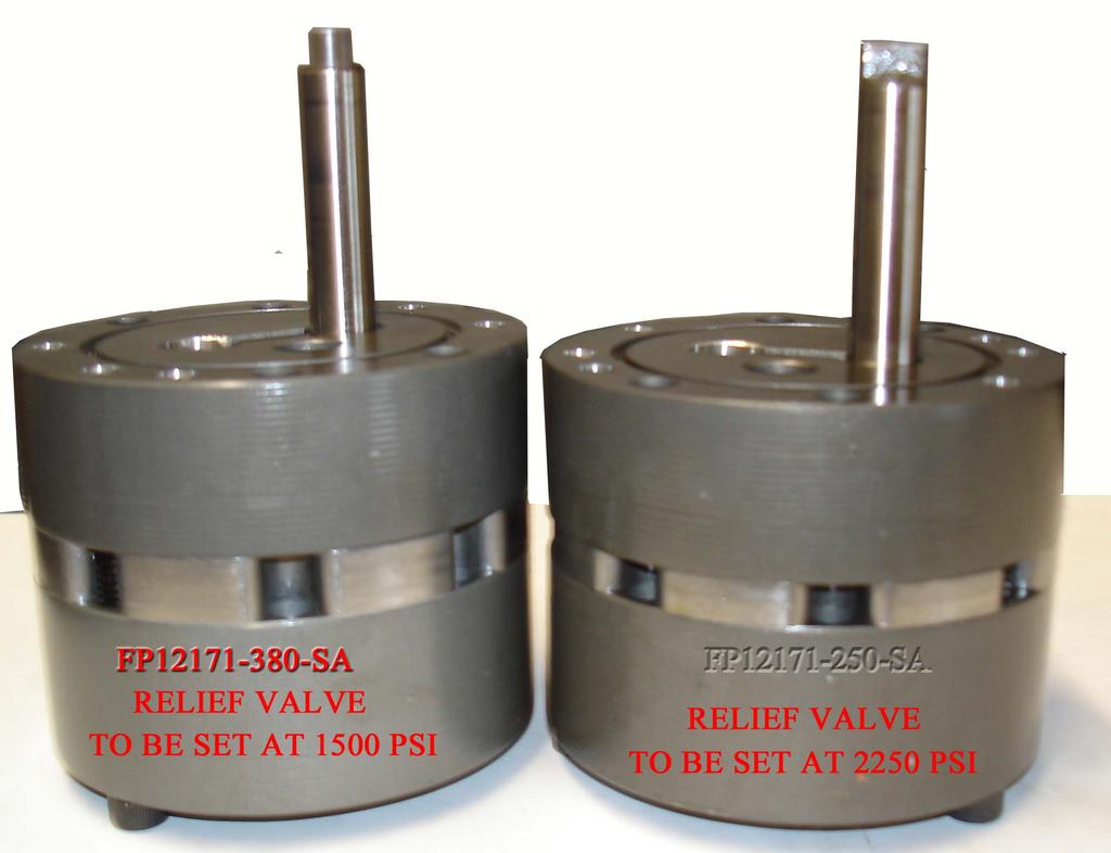
4 Arctic Equipment Manufacturing Corporation M3500V Power Unit R03 Hydraulic Pump The hydraulic pump converts mechanical energy transmitted by the prime mover (in this case a 12 volt DC electric motor) into hydraulic energy. The hydraulic energy is due to flow (kinetic energy) and pressure (potential energy). The rate of energy output is expressed in horsepower. At the inlet, as the gears un-mesh, the volume in the cavity increases thereby causing fluid to enter. This fluid is then carried between the gears and the housing to the other side of the gears into the outlet cavity. At this point the gear teeth mesh. The outlet cavity volume decreases, causing fluid to flow into the system. te that without a load, the pressure at the outlet port is nil. The pressure at the outlet of the pump is due to external loads placed on the system. These loads can be transmitted though cylinders and linear actuators as well as hydraulic motors and rotary actuators. In practice, system components by virtue of orifice and line sizes, offer some resistance to the flow of fluid. This translates into pressure at the outlet of the pump. Picture #1 Picture #2 Picture #1 Power unit used up to Pump used in this application was FP SA with a relief valve setting at 2250 psi. Picture #2 Power unit used Pump used in this application was FP SA with a relief valve setting at 1500 psi. Valve Information Pressure Relief Valve The pressure relief valve consists of a ball, a retaining spring and a seat. The ball is exposed to the pressure in the outlet line from the pump. This pressure acting on the exposed area of the
5 Arctic Equipment Manufacturing Corporation M3500V Power Unit R03 ball, causes a force on the retaining spring. When the pressure is such that the force on the ball exceeds the force in the spring (due to a preset amount of precompression) the ball lifts off the seat and the fluid from the outlet of the pump is allowed to flow back to the reservoir. The standard relief valve setting for the M3500V is 1500 psi. Directional Valves The M3500V circuit contains 7 directional valves identified as A1, A2', B, C, D1, D2' and E. Valves A1, A2', C, D1 and D2' are 3 way/ 2 position spool valves. Valve B is a 2 way/ 2 position normally closed poppet valve and valve E is 2 way/ 2 position normally open poppet valve. A basic directional valve consists of a valve cartridge and a coil. Inside the cartridge valve, an armature is attached to the valve mechanism. The coil consists of a wire wrapped around a spool. When power is applied to the coil (the coil is energized), the magnetic field created by coil pulls the armature into the coil. The armature shifts the valve mechanism into the energized position. When power is removed from the coil, a spring inside the valve cartridge pushes the armature and valve mechanism to the de-energized position. Directional Valve B Valve B is a 2 way/ 2 position normally closed poppet valve which is used for lowering the plow. In the de-energized position, valve B acts as a check valve allowing pump flow to the lift cylinder but preventing return flow from the lift cylinder to the reservoir. Energizing valve B opens the valve and allows flow from the lift cylinder to the reservoir thereby lowering the plow. te: the lift cylinder is connected to C3. Directional Valves A1, A2', C, D1, D2' Directional Valves A1, A2', C, D1 and D2 are 3 way/ 2 position spool valves. Directional Valve C operates the lift cylinder on C3 port. Directional Valves A1, A2' and D1, D2' operate the left and right angling double acting cylinders. Valves A1 and A2 operate the angling cylinder on the curb side of vehicle on C1 and C2 port. Valves D1 and D2' operate the angling cylinder on the driver side of vehicle on C4 and C5 port. In the de-energized position, the valves block flow from pump to the cylinder but allow return flow from the cylinder to the reservoir. In the energized position, flow from the pump to the cylinder is permitted but flow from the cylinder to the reservoir is not.
6 Arctic Equipment Manufacturing Corporation M3500V Power Unit R03 Directional Valve E Valve E is a 2 way/ 2 position normally open poppet valve. In the de-energized position, valve E allows flow that comes from C4 and C1 ports of the angling cylinders to the reservoir. When valve E gets energized (it gets energized only when blade is to be angled to the left or to the right), the valve gets closed and allows flow from the angle cylinder port C1 to be directed to second angle cylinder port C4 and vice versa. Valve E must be energized (activated) ONLY when plow is to be angled completely to the left or to the right (valve E gets energized pressing trigger switch on the handle of the joystick). Cross over relief valve The cross over relief valves are provided to protect the valves and manifold from the pressure spikes created when the plow strikes an object. The cross over relief valves are similar in construction to a regular direct acting relief valve. Cross over valves when activated, bleed fluid from one port to another or to the reservoir. In this manner the angling cylinders, the plow frame, and the truck frame are offered some protection from the normal impact forces associated with plowing. Striking a fixed object while plowing at high speeds will damage the cylinders and perhaps the plow. The cross over relief valves are adjustable and are normally set at about 3,000 psi. Pilot Operated (PO) Check Valve CVA and CVD A dual pilot operated check valve (PO Check Valve) is provided on ports C1 and C2 and on ports C4 and C5 to hold the plow at the desired angle. Without the PO Check valves, leakage through directional valves A1, A2', D1' and D2 would allow the plow to drift. Without pilot pressure, a pilot operated check valve (PO check valve) allows flow in only one direction. In the free flow direction, oil flowing through the valve lifts the poppet of the seat. In the opposite direction, returning oil pushes the poppet against the seat thereby blocking flow. When pressure is applied to the pilot piston, the poppet is lifted off the seat and flow in both directions is permitted. Control Switch The M3500V uses a handheld controller or a joystick control box with following operations: raise, lower, angle right, angle left, vee, scoop, right blade section retracted, right blade section extended, left blade section retracted and left blade section extended.
7 Arctic Equipment Manufacturing Corporation R02 M3500V Power Unit fluid from one port to another or to the reservoir. In this manner both the angling cylinders, the plow frame and the truck frame are offered some protection from the normal impact forces associated with plowing. Striking a fixed object while plowing at high speeds will damage the cylinders and perhaps the plow. The cross over relief valves are adjustable and are normally set at about 3,000 psi. Pilot Operated (PO) Check Valve CVA and CVD A dual pilot operated check valve (PO Check Valve) is provided on ports C1 and C2 and on ports C4 and C5 to hold the plow at the desired angle. Without the PO Check valves, leakage through directional valves A1, A2', D1' and D2 would allow the plow to drift. Without pilot pressure, a pilot operated check valve (PO check valve) allows flow in only one direction. In the free flow direction, oil flowing through the valve lifts the poppet of the seat. In the opposite direction, returning oil pushes the poppet against the seat thereby blocking flow. When pressure is applied to the pilot piston, the poppet is lifted off the seat and flow in both directions is permitted. Control Switch The M3500V uses joystick control box with following operations: raise, lower, angle right, angle left, vee, scoop, right blade section retracted, right blade section extended, left blade section retracted and left blade section extended.
8
9
10
11
12
13
14
15
16
17
18
19 Arctic Equipment Manufacturing Corporation Power Unit Kit M3500V for V plow blade R06 INST0053 M3500V installation instructions
20 Arctic Equipment Manufacturing Corporation Power Unit Kit M3500V for V plow blade R06 INST0053 M3500V installation instructions Warning: -Top of battery needs to be protected. If positive side of battery is accidentally grounded person could be burnt or wiring system can be damaged, or battery gasses could explode causing injuries. -Disconnect cable from negative battery terminal before start installation. -Always wear eye protection and protective clothing when working around hydraulic systems. -Remove jewelry and objects that might conduct electricity while working on power units. -Fluid under pressure can pierce the skin and enter the bloodstream causing death or serious injury. - Hydraulic hoses and electrical cables (harnesses) must be tied and routed safely to avoid any damage and pinching (away from hot places, sharp objects etc.). te :Do not use Teflon tape on hydraulic fittings as it can easily jam valves and plug the filters in the system. Apply dielectric grease to all connections to prevent corrosion Use of fluid other than J13 will void warranty 1. Install colour co-ordinated weather cover (8) on cable and plug assembly (4). Attach red lead to positive motor stud and black lead to negative motor stud. Liberally coat connections with dielectric grease then slide covers over the eyes on the end of the cables. 2. Install power unit (1) and mounting plate (2) with motor toward driver s side of truck (use star washers under bolts to bolt the pump plate to the lift frame - use star washers AND removable grade Loctite to fasten power unit to the pump plate). 3. Route power unit harness through grommet in driver s side of mounting plate and secure using cable clamp (attached to power unit harness) and ¼ x 1 bolt. 4. Mount solenoid (35) to metal surface in engine compartment bending bracket if necessary. Be sure to locate the solenoid so that there is sufficient cable to reach to both the battery and the cable and plug assembly (4) on the power unit. NOTE: Solenoid must be well grounded in order to function properly. 5. Slide weather cover (10) over power cable (6) and ground cable (5) and route through grille of truck leaving sufficient length to attach to the cable and plug assembly (4). Secure the red power cable (6) to the large terminal on the solenoid and the black ground cable (5) to the negative terminal on the battery. 6. Secure power cable (7) from other large terminal on solenoid to positive terminal on battery.
21 Arctic Equipment Manufacturing Corporation Power Unit Kit M3500V for V plow blade R06 INST Plug intermediate under hood harness (33) into valve section harness (34) and follow battery cable routing toward firewall. Locate a pass through hole in the firewall near the driver s side of the truck. Route other end of intermediate under hood harness (33) through the hole in firewall and attach to the intermediate in cab harness(32). Intermediate in cab harness must be secured under the dash and it should be attached to control station (te: White wire must be attached under the dash(ground)). 8. Attach black wire to positive side of solenoid and brown wire to small terminal on top of the solenoid (35). 9. Neatly secure all excess cables and wires using tie straps. Silicone hole in firewall. te: Be sure all cables are properly protected from any sharp edges or hot or moving parts!! 10. Install hoses and fittings as shown on drawing for hose and fitting installation. 11. Remove vent cap and fill reservoir with UNIVIS J13 (HVI 13) hydraulic oil. Do not use automatic transmission fluid in this system as it may lead to aeration of the oil in very cold weather conditions. Use of fluid other than J13 will void warranty. 13. Manually angle one section of the blade to one side before activating the power unit. This can be easily accomplished, as the hose connections are loose at the angling cylinders. 14. Jog the joystick (extend and retract cylinder),operate only section of the blade that was manually extended, until no air is seen in the fluid passing through the loose connection. Tighten fittings. 15. Refill power unit. Repeat same steps for second section of the blade. 16. Refill power unit. Jog the joystick to lift blade until no air is seen in the fluid passing through the loose connection. Tighten fittings. 17. Refill power unit so that oil level is ¾ from the top of the reservoir. Clean up any spilled oil and check all functions several times making sure there is not excessive foaming in the reservoir. Compress the lift cylinder and double check the oil level. Check for leaks at all fittings. 18. Install power unit cover (13).
22 Arctic Equipment Manufacturing Corporation Power Unit Kit M3500V for V plow blade R06 INST0053 Power Unit Kit M V plow Item Part # Description Quantity 1 M B01E Power Unit V plow M Mounting plate ass y (includes pump plate, pump plate cover, bolts etc.) " Cable Plug Assembly " Ground Cable " Power Cable " Battery Cable N Red Terminal Protector 1 * Dummy Plug (power and ground) 1 * N Dummy Plug (V plow) M 29" Hose 3 * C Power Unit Cover 1 14 HH deg Swivel Elbow M 36" Hose 2 18 CS NRS 2 x 6 Lift Cylinder N Grommet 1/4"x1.3/4X2.1/ HH /4-20x1 Hex Head Cap Screw 1 22 HH /8-16x1 Hex Head Cap Screw N 3/8" Star Lockwasher HH /16-24x1.1/4 Hex Head Cap Screw 4 26 HH /16-24 Hex Nut N 5/16" Star Lockwasher 2 28 HH /4-20 Hex Nut 1 29 HH /4 Lockwasher 1 30 HH /16-24x1 Hex Head Cap Screw N Plastic Drain Hole Plug 1
23 Arctic Equipment Manufacturing Corporation Power Unit Kit M3500V for V plow blade R06 INST0053 Power Unit Kit M V plow Item Part # Description Quantity B Incab Intermediate Harness 7" B Underhood Intermediate Harness 97" B Valve Section Harness 26" 1 35 FP17757 Solenoid 1 36** NRS Cylinder, 2" x 9" 2 37*** M Joystick Ass y (incl. joystick and bracket) 1 *Items not shown on drawing **52873-N is part of power angling kit. *** M is not part of this kit (it is sold separately).
24
25

26
27 Arctic Equipment Manufacturing Corporation M3500V Power Unit R03 M3500V Parts List (up to 2012) Rev Ref # Qty Part # Description R FP18442 Motor,ISKRA, 12 VDC with ground stud 1a 1 FP8714 Brush Kit for ISKRA Motor (FP b M Brush Kit for Prestolite Motor (FP8034) * 2 1 FP Pump base assembly M3593 2a 1 FP7985 Needle Bearing (Pump Shaft to Pump Base) 3 1 FP Reservoir, 4-1/2 DIA x 8 length 4 1 FPN0854-SA Manifold assembly (incl. all valves) 4a 1 FPN Manifold only 5 1 FP1209 Suction tube 6 1 FP13058 Return tube 7 1 FP1134 Suction filter 8 2 FP0118 O-ring, 5/8 x ¾ x 1/ FP7346 Valve, PO check valve (CVA, CVD) 10 4 FP13023 X over valve assembly (XA1, XA2, XD1, XD2) 10a 1 FP7899 Screw 10b 1 FP0386 Sealing nut 10c 1 FP0147 Spring 10d 1 FP1288 Plate 10e 1 FP0379 Housing 10g 1 FP0012 Ball 10h 1 FP0378 Seat R FP0490-D Valve, #8, 2W / 2P, NC poppet (B) R04 11a 1 FP10861-D Coil #8, 2W / 2P 12V R04 11b 1 FP10907-D Valve cartridge, #8, NC poppet R FP7249-D Valve, #8, 3W / 2P, c/w spade terminal (A1, D1, A2, D2, C) R04 12a 1 FP18835-D Coil, 12 VDC, #8, with spade terminal R04 12b 1 FP0679-D Valve cartridge, #8 spool, 3W / 2P 13 1 FP Pressure compensated flow control 14 1 FP3274 Plug, SAE # FP7526 Check valve kit 16 1 FP2352 O-ring, 3-5/8 x 3-7/8 x 1/8, FP7527 Relief valve,(flat washer FPN0575/seal washerfp FPN0572 Breather 19 6 FP7703 Screw, x 3/8 self tapping 20 1 FP SA Pump assembly kit 21 5 FP1316 Filter, screen 22 5 FP7624 Screw, filter retainer 23 4 FPN0748 Screw, SHCS, ¼-20 x B Harness, valve section
28 Arctic Equipment Manufacturing Corporation M3500V Power Unit R03 M3500V Parts List (up to 2012) Rev Ref # Qty Part # Description B Underhood intermediate harness B Incab intermediate harness R FPN0862-SA-D Valve assembly #8, NO poppet, 12 VDC (E) R04 27a 1 FP18835-D Coil #8 with spade terminal R04 27b 1 FP7276-D Valve cartridge #8, NO poppet N Control station, joystick R FP17757 Solenoid, switch R N Plug, SAE O ring 7/ FP2159 Pump shaft seal 33 1 FP2318 Motor bearing Spade connector, male ¼ tab, insulated, 20 g wire A Motor to Base Ground Wire M Handheld Controller (V Blade only) * Items t Shown on Drawing R01: FP18442 replaces FP8034 R02: FP17757 replaces FP7518 R03:Added drain plug R04:FP0490-D replaces FP0490 -FP10861-D replaces FP0496 *note: if Deltrol coil FP0496 is replaced with Deltrol coil FP10861-D Deltrol cartridge FP0307 must also be changed to Deltrol cartridge FP10907-D. -FP10907-D replaces FP0307 *note: if Deltrol cartridge FP0307 is replaced with Deltrol cartridge FP10907-D, Deltrol coil FP0496 must also be changed to Deltrol coil FP10861-D. -FP7249-D replaces FP7249 -FP18835-D replaces FP FP0679-D replaces FP0679 *note: if Parker cartridge FP0679 is replaced with FP0679-D, Parker coil FP10977 must also be changed to Deltrol FP18835-D. -FP7276-D replaces FPN0565 *note: If Parker cartridge FPN0565 is replaced with Deltrol cartridge FP7276-D Parker valve FP10977 must also be changed to Deltrol coil FP18835-D. -FPN0862-SA-D Replaces FPN0862-SA


29
30 Arctic Equipment Manufacturing Corporation M3500V Power Unit R03 M3500V Power unit (2012+) Ref # Part # Description Qty 1 FP8111 Motor 1 2 FP18405 Pump base assembly 1 3 FP6102 Reservoir 1 4 FP18411 Manifold assembly (incl. all valves) 1 5 FP1209 Suction tube 1 6 FP13058 Return tube 1 7 FP1134 Suction filter 1 8 FP0118 O-ring, 5/8 x ¾ x 1/ FP7346 Valve, PO check valve (CVA, CVD) 2 10 FP13023 X over valve assembly (XA1, XA2, XD1, XD2) 4 10a FP7899 Screw 1 10b FP0386 Sealing nut 1 10c FP0147 Spring 1 10d FP1288 Plate 1 10e FP0379 Housing 1 10g FP0012 Ball 1 10h FP0378 Seat 1 11 FP0490-D Valve, #8, 2W / 2P, NC poppet (B) 1 11a FP10861-D Coil #8, 2W / 2P 12V 1 11b FP10907-D Valve cartridge, #8, NC poppet 1 12 FP7249-D Valve, #8, 3W / 2P, c/w spade terminal (A1, D1, A2, 5 D2, C) 12a FP18835-D Coil, 12 VDC, #8, with spade terminal 1 12b FP0679-D Valve cartridge, #8 spool, 3W / 2P 1 13 FP2361 Orifice N Plug, SAE #4 (7/16 ) 1 15 FP7526 Check valve kit 1 16 FP2352 O-ring, 3 3/4 x 4 x 1/8, FP7527 Relief valve,(flat washer FPN0575/seal washer FP3874) 1 18 FPN0571 Breather 1 19 FP7985 Needle Bearing 1 20 FP SA Pump assembly kit 1 21 FP18410 Manifold only 1 22 FP7900 Clamp, (clamp up to 80inlb) 1 23 FP7752 Screw, SHCS, ¼ x 2 3/ B Harness, valve section B Underhood intermediate harness B Incab intermediate harness 1 27 FPN0862-SA-D Valve assembly #8, NO poppet, 12 VDC (E) 1 27a FP18835-D Coil #8 with spade terminal 1 27b FP7276-D Valve cartridge #8, NO poppet N Control station, joystick 1
31 Arctic Equipment Manufacturing Corporation M3500V Power Unit R03 M3500V Power unit (2012+) Ref # Part # Description Qty 29 FP17757 Solenoid, switch 1 30 FP2159 Pump shaft seal 1 31 FP2318 Motor bearing M Handheld Controller (V Blade only) 1
32
 Cavity without identification mark (without Greek")
 Cavity with identification mark - Greek letter")
 Valve replacement a) Cavity and O-ring must be selected correctly for proper sealing function, the rest of the valve is the same.")
33 Valves 2 way /2 position (2w/2p) cavity (O-ring) change 1. Power units manufactured prior to 2010 Typically manufactured with "Monarch-style" valve cavity, identifiable by: a) Cavity without identification mark (without Greek letter delta (triangle)) (see picture 1) b) Black O-ring, with 0.070" cross-section (see picture 3) 2. Units manufactured in 2010 and beyond Typically manufactured with "Industry standard" valve cavity, identifiable by: a) Cavity with identification mark - Greek letter delta (triangle) (see picture 2) b) Blue O-ring, with cross-section (see picture 3) Valve replacement a) Cavity and O-ring must be selected correctly for proper sealing function, the rest of the valve is the same. If necessary, replace O-ring with the proper O-ring to match the valve cavity: b) Cavity without identification mark requires black O-ring, with 0.070" cross-section (see picture 3) c) Cavity with identification mark requires blue O-ring, with cross-section (see picture 3) Picture 1 Picture 2 Picture 3
34 Troubleshooting flow chart for power unit M3500V - Motor does not operate. - Motor operates continuously. - Snow plow does not raise. - Snow plow raises up very slow. - Snow plow will not lower. - Snow plow leaks down. - Snow plow angles before going up when up switch is pressed. - Snow plow when is fully angled going up when angle switch is pressed. - Snow plow does not go in vee position. - Snow plow does not go in scoop position. - Right wing does not extend. - Right wing does not retract. - Left wing does not extend. - Left wing does not retract. - Snow plow does not hold angle. *WARNING* -Fluid under pressure can pierce the skin and enter the bloodstream resulting in serious injury or death. -Eye protection and protective clothing must be worn when working on any portion of the snowplow. -Remove any jewellery (rings, bracelets, watches, necklaces) that could conduct electricity while working with electrical system. -Lifted blade should be securely propped or immobilized while working on it or any other suspended part so it cannot fall. -Do not operate blade when anyone is within a 10 foot radius of it. -Do not use Teflon tape on hydraulic fittings as it can easily jam valves and plug the filters in the system. Specification: -Max Amp Draw 230 AMP (AMP draw of motor should be measured at maximum raise or maximum angle when motor is running at relief pressure setting). te: Do not operate motor continuously for more than 30 sec -X-over relief valve setting 3000 psi. -te: Quick couplers are an optional item. If unit is not equipped with quick couplers, disregard troubleshooting steps involving them. Power unit Pump used FP SA a relief valve setting at 1500 psi Power unit up to 2012 Pump used FP SA a relief valve setting at 2250 psi.
35 Troubleshooting tips M3500V: te: For power unit up to 2012 relief valve setting is 2250 psi, and for power units setting is 1500 psi. 1. Pump shaft can be turned freely (smoothly) using two fingers. If it can t be turned replace pump. Proper pump rotation is clockwise looking from the motor end. 2. Use a screwdriver to check magnetism of solenoid coils. Place screwdriver on the nut securing the coil and have the switch operated. Strong magnetic attraction should be felt. 3. Measure pump pressure at an angle hose (at full angle)(assuming that cross over relief valve setting is 3000 psi, if X-over relief valve setting is less than relief valve setting pressure gage will read lowest reading). The most accurate reading of system pressure is reading pressure on lift cylinder. When testing or making adjustments on the relief valve the system must be dead headed (cylinder at full stroke or in a position where cylinder movement is zero). 4. AMP draw of motor should be measured at maximum raise or maximum angle when motor is running. 5. Use volt meter or test light to test for power in a harness or continuity in a switch. A test light is simply a light bulb which has one end connected by a wire to an alligator clip and the other end connected to a metal probe. It is used to check the electrical circuit when the battery is connected to the system. The alligator clip is grounded and the light glows when the probe comes in contact with a live electrical component. 6. Do not screw cartridge valves into cavity too fast; use a back and forth motion and have O-rings well lubricated. 7. Clean all parts thoroughly before assembly and lubricate with clean oil. 8. Do not use Teflon tape on hydraulic connections as it can easily jam the valves and plug the filters in the system, use pipe sealant. Never apply pipe sealant at the end of fitting, always 2-3 threads back. 9. X-over pressure could be set using hand (hydraulic) pump. Example: If you want to set the pressure at x-over XA1 insert hand pump hose in the C1 port together with pressure gage. Loosen the jam nut and turn adjusting screw clockwise a turn or two and watch the gauge; if it goes up, continue to turn the screw until the required setting is reached. Retighten the jam nut. To set X- overs XA2, XD1 and XD2 repeat the same steps as setting XA1. 10.To adjust relief valve: a. Loosen jam nut counter-clockwise. b. Turn screw clockwise to increase pressure or turn screw counter-clockwise to decrease pressure.c. Tighten jam nut clockwise to 50in.lb. torque.d. Check system pressure after jam nut is tight. Readjust pressure if screw is moved during tightening of jam nut. R01
36 Is there power at the positive motor stud? Is there good ground connection? yes Remove motor. Will it run when 12V is applied? Is pump shaft seized? Replace pump. MOTOR DOES NOT OPERATE M3500V Clean and tighten all connections. Electrical connections must be free of corrosion and tight. Repair (check brushes)/ replace motor. Is there power on the motor terminal of solenoid, when joystick is activated (up or angling)? Is there power to control terminal wire (brown wire) when joystick is operated (up or angling)? Is battery charged? Battery terminals and all electrical connections must be free of corrosion and tight. Charge battery. Is there power to control terminal wire? Is there power leaving joystick? Repair/ replace incab/underhood intermediate harness. Are all connections from (motor/ solenoid) clean and tight? Clean and tighten all electrical connections. Check that solenoid is grounded. If there is good ground connection to solenoid and motor does not operate, replace solenoid. Hint: If you do not hear "click" sound from solenoid when joystick is operated in any position (except lower), replace solenoid (assuming there is good ground connection to solenoid). Are harnesses (connectors) plugged in each other properly? Replace fuse (check for a short in harness/ motor/ switch) Is the fuse (10 amp)ok? Replace joystick. MOTOR OPERATES CONTINUOUSLY M3500V If motor operates continuously, change solenoid. R01
37 SNOW PLOW DOES NOT RAISE M3500V Does the motor operate when joystick is operated to raise plow? Is fluid level 3/4" below filler hole? Does motor operate when joystick is operated in any position (except down)? See chart - Motor does not operate. Add UNIVS J13 oil. Replace joystick. Is there pressure in angle cylinder port when angle switch is pressed? (Use pressure gauge)(hint:check relief valve condition.) Is motor Is suction turning in filter proper plugged? direction? Adjust relief valve to 2250 psi/1500 psi. Can it be done? Using a gauge in the pressure line, loosen the jam nut and turn adjusting screw clockwise a turn or two and watch the gauge; if it goes up, continue to turn the screw until the required setting is reached. Retighten the jam nut. Repair/replace motor. Does pump shaft turn freely? Does the motor armature turn tightly? Replace pump. Replace suction filter. Change oil and flush system. Is there Does plow raise up? Replace pump. Is there power to C coil (blue wire) when joystick is Repair/ replace motor. Is there power leaving joystick when joystick is operated to raise plow? Replace joystick. Is there power in each harness? Are harness connectors plugged into each other properly? Is there magnetism on C coil. Replace C valve coil. Replace C valve cartridge. Repair/replace harness that does not have power. R01
38 SNOW PLOW RAISE VERY SLOW M3500V Is fluid level 3/4" below filler hole? Add UNIVS J13 oil. Adjust relief valve to 2250 psi/1500 psi. Can it be done?using a gauge in the pressure line, loosen the jam nut and turn adjusting screw clockwise a turn or two and watch the gauge; if it goes up, continue to turn the screw until the required setting is reached. Retighten the jam nut.(hint:check relief valve condition.) Does plow raise up Replace C cartridge valve. Does pump shaft turn freely? Replace pump. Clean/ replace suction filter. Change oil and flush system. Does the motor armature turn tightly? Repair/ replace motor. R01
39 Does B (valve) coil (orange wire) have magnetism? Replace cartridge valve B. Does plow lower down? SNOW PLOW WILL NOT LOWER M3500V Is there power leaving joystick when joystick is Is there power to the operated to lower plow? B coil? Replace Coil B. Is there power in each harness? Replace joystick. Are harness connectors plugged into each other properly? Clean/replace flow control valve FC1. Does plow lower down? Replace C valve. Does plow lower down? Check for bent or seized cylinder. Repair/replace harness that does not have power. SNOW PLOW LEAKS DOWN M3500V Fix any leakage from cylinder or fittings or hose. Is plow still going down? Clean/replace B valve cartridge. SNOW PLOW ANGLES BEFORE IT GOES UP WHEN JOYSTICK IS OPERATED TO RAISE PLOW M3500V If snow plow angles before it goes up change following cartridge: A2 if right wing retracts, A1 if right wing extends, D2 if left wing retracts, D1 if left wing extends SNOW PLOW WHEN IS ANGLED IT GOES UP WHEN JOYSTICK IS OPERATED TO ANGLE PLOW M3500V Change C Valve cartridge. R01
40 SNOW PLOW DOES NOT ANGLE TO RIGHT SIDE M3500V Does the motor operate when joystick is operated to angle right (note: triger switch must be activated)? Does motor operate when joystick is operated in any position (except down)? Replace joystick. Does A2 coil (green wire) have magnetism? See chart - Motor does not operate. Is there power to A2 coil (green wire)? Is there power leaving joystick? Replace switch joystick. Replace A2 cartridge valve. Does it angle to right side? Replace A2 coil. Is there power in each harness? Are harness connectors plugged into each other properly? Clean/replace cross over relief valves XA1 and XA2. Check setting 3000 psi. Does it angle to right side? Clean/replace PO check valve (CVA). Does it angle to right side? Does E coil (yellow wire) have magnetism? Is there power to E coil (yellow wire)? Repair/replace harness that does not have power. Replace E coil. Change quick couplings. Does it angle to right side? Replace E cartridge valve. Does it angle to right side? Is there power in each harness? Are harness connectors plugged into each other properly? Check for a bent or seized cylinder. Is there power leaving joystick? Replace joystick. Repair/replace harness that does not have power. te: Before start troubleshooting check that plow moves up and down. If plow does not move up and down see "plow does not raise". R01
41 SNOW PLOW DOES NOT ANGLE TO LEFT SIDE M3500V Does the motor operate when joystick is operated to angle left (note: triger switch must be activated)? Does D2 coil (red wire) have magnetism? Does motor operate when joystick is operated in any position (except down)? See chart - Motor does not operate. Is there power to D2 coil (red wire)? Is there power leaving joystick? Replace joystick. Replace joystick. Replace D2 cartridge valve. Does it angle to left side? Replace D2 coil. Is there power in each harness? Are harness connectors plugged into each other properly? Clean/replace cross over relief valves XD1 and XD2. Check setting 3000 psi. Does it angle to left side? Change quick couplings. Does it angle to left side? Check for a bent or seized cylinder. Clean/replace PO check valve (CVD). Does it angle to left side? Does E coil (yellow wire) have magnetism? Replace E cartridge valve. Does it angle to left side? Replace joystick. Is there power to E coil (yellow wire)? Is there power in each harness? Is there power leaving joystick? Repair/replace harness that does not have power. Replace E coil. Are harness connectors plugged into each other properly? Repair/replace harness that does not have power. te: Before start troubleshooting check that plow moves up and down. If plow does not move up and down see "plow does not raise". R01
42 PLOW DOES NOT GO IN VEE POSITION M3500V 1 of 2 Does the motor operate when joystick is operated in vee position? Does motor operate when joystick is operated in any position (except down)? Replace joystick. Does blade move at all when joystick is operated in Vee position? Does only left wing retract when joystick is operated in Does A2 coil (green wire) have magnetism? Replace A2 cartridge valve. Does plow go in Replace E cartridge valve. See chart - Motor does not operate. Is there power to A2 coil (green wire)? Replace A2 coil. Is there power leaving joystick? Is there power in each harness? Replace joystick. Are harness connectors plugged into each other properly? Clean/replace cross over relief valves XA1 and XA2. Check setting 3000 psi. Does plow go in vee position? Clean/replace PO check valve (CVA). Does plow go in vee position? Change quick couplings. Does plow go in vee position? Repair/replace harness that does not have power. Check for a bent or seized cylinder. Go to the next page. te: Before start troubleshooting check that plow moves up and down. If plow does not move up and down see "plow does not raise". Page 9 of 17 R0
43 PLOW DOES NOT GO IN VEE POSITION M3500V 2 of 2 Does D2 coil (red wire) have magnetism? Does only right wing retract when joystick is operated in vee position? Replace D2 cartridge valve. Does plow go in Is there power to D2 coil (red wire)? Replace D2 coil. Is there power leaving joystick? Is there power in each harness? Replace joystick. Are harness connectors plugged into each other properly? Clean/replace cross over relief valves XD1 and XD2. Check setting 3000 psi. Does plow go in vee position? Clean/replace PO check valve (CVD). Does plow go in vee position? Change quick couplings. Does plow go in vee position? Repair/replace harness that does not have power. Check for a bent or seized cylinder. te: Before start troubleshooting check that plow moves up and down. If plow does not move up and down see "plow does not raise". R01
44 PLOW DOES NOT GO IN SCOOP POSITION M3500V 1 of 2 Does the motor operate when joystick is operated in scoop position? Does only left wing extend when joystick is operated in scoop position? Does A1 coil (gray wire) have magnetism? Replace A1 cartridge valve. Does plow go in Does motor operate when joystick is operated in any position (except down)? See chart - Motor does not operate. Is there power to A1 coil (gray wire)? Replace A1 coil. Is there power leaving joystick? Is there power in each harness? Replace joystick. Replace joystick. Are harness connectors plugged into each other properly? Clean/replace cross over relief valves XA1 and XA2. Check setting 3000 psi. Does plow go in scoop position? Clean/replace PO check valve (CVA). Does plow go in scoop position? Change quick couplings. Does plow go in scoop position? Repair/replace harness that does not have power. Check for a bent or seized cylinder. Go to the next page. te: Before start troubleshooting check that plow moves up and down. If plow does not move up and down see "plow does not raise". R01
45 PLOW DOES NOT GO IN SCOOP POSITION M3500V 2 of 2 Does D1 coil (purple wire) have magnetism? Does only right wing extend when joystick is operated in scoop position? Replace D1 cartridge valve. Does plow go in Is there power to D1 coil (purple wire)? Replace D1 coil. Is there power leaving joystick? Is there power in each harness? Replace joystick. Are harness connectors plugged into each other properly? Clean/replace cross over relief valves XD1 and XD2. Check setting 3000 psi. Does plow go in scoop position? Clean/replace PO check valve (CVD). Does plow go in scoop position? Change quick couplings. Does plow go in scoop position? Repair/replace harness that does not have power. Check for a bent or seized cylinder. te: Before start troubleshooting check that plow moves up and down. If plow does not move up and down see "plow does not raise". R01
46 RIGHT WING DOES NOT EXTEND M3500V Does the motor operate when joystick is operated to extend right wing? Does motor operate when joystick is operated in any position (except down)? Replace joystick. Does A1 coil (gray wire) have magnetism? See chart - Motor does not operate. Is there power to A1 coil (gray wire)? Is there power leaving joystick? Replace joystick. Replace A1 cartridge valve. Does wing extend? Replace A1 coil. Is there power in each harness? Are harness connectors plugged into each other properly? Clean/replace cross over relief valves XA1 and XA2. Check setting 3000 psi. Does wing extend? Clean/replace PO check valve (CVA). Does wing extend? Change quick couplings. Does wing extend? Repair/replace harness that does not have power. Check for a bent or seized cylinder. te: Before start troubleshooting check that plow moves up and down. If plow does not move up and down see "plow does not raise". R01
47 RIGHT WING DOES NOT RETRACT M3500V Does the motor operate when joystick is operated to retract right wing? Does motor operate when joystick is operated in any position (except down)? Replace joystick. Does A2 coil (green wire) have magnetism? See chart - Motor does not operate. Is there power to A2 coil (green wire)? Is there power leaving joystick? Replace joystick. Replace A2 cartridge valve. Does wing retract? Replace A2 coil. Is there power in each harness? Are harness connectors plugged into each other properly? Clean/replace cross over relief valves XA1 and XA2. Check setting 3000 psi. Does wing retract? Clean/replace PO check valve (CVA). Does wing retract? Change quick couplings. Does wing retract? Repair/replace harness that does not have power. Check for a bent or seized cylinder. Does plow go to the right when it is only operated function to retract right wing? Replace E cartridge valve. te: Before start troubleshooting check that plow moves up and down. If plow does not move up and down see "plow does not raise". R01
48 LEFT WING DOES NOT EXTEND M3500V Does the motor operate when joystick is operated to extend left wing? Does motor operate when joystick is operated in any position (except down)? Replace joystick. Does D1 coil (purple wire) have magnetism? See chart - Motor does not operate. Is there power to D1 coil (purple wire)? Is there power leaving joystick? Replace joystick. Replace D1 cartridge valve. Does wing extend? Replace D1 coil. Is there power in each harness? Are harness connectors plugged into each other properly? Clean/replace cross over relief valves XD1 and XD2. Check setting 3000 psi. Does wing extend? Clean/replace PO check valve (CVD). Does wing extend? Change quick couplings. Does wing extend? Repair/replace harness that does not have power. Check for a bent or seized cylinder. te: Before start troubleshooting check that plow moves up and down. If plow does not move up and down see "plow does not raise". R01
49 LEFT WING DOES NOT RETRACT M3500V Does the motor operate when joystick is operated to retract left wing? Does motor operate when joystick is operated in any position (except down)? Replace joystick. Does D2 coil (red wire) have magnetism? See chart - Motor does not operate. Is there power to D2 coil (red wire)? Is there power leaving joystick? Replace joystick. Replace D2 cartridge valve. Does wing retract? Replace D2 coil. Is there power in each harness? Are harness connectors plugged into each other properly? Clean/replace cross over relief valves XD1 and XD2. Check setting 3000 psi. Does wing retract? Clean/replace PO check valve (CVD). Does wing retract? Change quick couplings. Does wing retract? Repair/replace harness that does not have power. Check for a bent or seized cylinder. Does plow go to the left when it is only operated function to retract left wing? Replace E cartridge valve. te: Before start troubleshooting check that plow moves up and down. If plow does not move up and down see "plow does not raise". R01
50 PLOW DOES NOT HOLD ANGLE M3500V Are cylinders spongy? Can wing be moved 2" to 6" by hand? Check cross over valves XA1 and XA2 for right wing and XD1 and XD2 for left wing. Clean/ replace. Replace seat if necessary. Check setting to 3000 psi. Does it hold angle? Check pressure operated check valve CVA for right wing and CVD for left wing. Clean/ replace. Bleed air from cylinders. Check for any loose connections. R01
Arctic Equipment Manufacturing Corporation M3493 Hydraulic Power Unit. Table of Contents
 M3493 Hydraulic Power Unit Table of Contents Operating information...2 Hydraulic Operational Diagrams...6 Hydraulic & Electrical Installation...10 Parts List...16 Troubleshooting...22 M3493 Power Unit
Arctic Equipment Manufacturing Corporation M3551 Hydraulic Power Unit. Table of Contents
 Arctic Equipment Manufacturing Corporation M3551 Hydraulic Power Unit Table of Contents General Information...2 Hydraulic Information Diagrams...7 Hydraulic and Electrical Installation...10 Parts List...11
Arctic Equipment Manufacturing Corporation M3593 Hydraulic Power Unit. Table of Contents
 Arctic Equipment Manufacturing Corporation M3593 Hydraulic Power Unit Table of Contents General Information...2 Hydraulic Operational Diagrams...8 Hydraulic & Electrical Installation Hi Boy & Hi Boy DLC...13
Troubleshooting flow chart for power unit M3593
 Troubleshooting flow chart for power unit M3593 - Motor does not operate. - Motor operates continuosly - Snow plow does not raise. - Snow plow raises up very slow. - Snow plow will not lower. - Snow plow
Table of Contents. M673f- old
 Table of Contents General Information. 2 Hydraulic & Electrical Operational Diagrams.8 Hydraulic & Electrical Installation 17 Parts List...23 Troubleshooting.28 Page 1 M673010-01L06E (old version) Operating
Arctic Equipment Manufacturing Corporation R04 M673F Power Unit Kit Installation Instructions. M673F installation instructions
 Arctic Equipment Manufacturing Corporation R04 M673F Power Unit Kit Installation Instructions M673F installation instructions Arctic Equipment Manufacturing Corporation R04 M673F Power Unit Kit Installation
Table of Contents.
 3551 Table of Contents Operating Information...2 Hydraulic Information Diagrams...7 Hydraulic and Electrical Installation...10 Parts List...11 Troubleshooting...15 Page 1 M3551 M3551 Operating Information
One piece harness installation instructions (standard wiring) with 2 plugs 2018 & After
 with 2 plugs 2018 & After") One piece harness installation instructions (standard wiring) with 2 plugs 2018 & After (it requires light kit 800084,800085 or 800086) Page 1 Installation instructions Warning: - Top of battery needs
One piece harness installation instructions (standard wiring) with 2 plugs 2018 & After (it requires light kit 800084,800085 or 800086) Page 1 Installation instructions Warning: - Top of battery needs
One piece harness installation instructions (standard wiring) with 2 plugs
 with 2 plugs") One piece harness installation instructions (standard wiring) with 2 plugs (it requires light kit 800084 or 800086) Page 1 Installation instructions Warning: - Top of battery needs to be protected. If
One piece harness installation instructions (standard wiring) with 2 plugs (it requires light kit 800084 or 800086) Page 1 Installation instructions Warning: - Top of battery needs to be protected. If
Table of Contents M3593
 Table of Contents M3593 Operating information...2 Hydraulic Operational Diagrams...7 Hydraulic Installation M3593 (one piece and MPX).. 12 Hydraulic Installation-HI boy & HI-Boy-DLC...16 High mount Installation
One piece harness installations...2 Adapter Harness Controller for straight blade...26 Controller for wing blade.27 Controller for V blade..
 One piece harness installation Table of Contents One piece harness installations...2 Adapter Harness... 16 Controller for straight blade...26 Controller for wing blade.27 Controller for V blade..28 Page
 Table of Contents Multiplexing Reinstallation- under hood (53618-01-M) (2017 & beyond)... 3 Multiplexing installation under hood (53618-02-M) (2017 & beyond).....19 Two Piece Plug MPX Underhood Harness
Multiplexing system installation M
 MPX installation 53618-M Multiplexing system installation (the control module installed under power unit (pump cover) 53618-M (it requires light kit 800084 or 800086) Link to Install MPX controller harness
One piece harness installations... 2 Adapter Harness... 16
 One piece harness installation Table of Contents One piece harness installations... 2 Adapter Harness... 16 Page 1 www.arcticsnowplows.com One piece harness installation One piece harness installation
 Table of Contents Multiplexing Reinstallation- under hood (53618-01-M) (Prior 2017)..... 3 Multiplexing installation under hood (53618-02-M) (Prior 2017).....19 One Piece Plug MPX Undehood Harness (53470-MPX)
 Table of Contents Multiplexing Installation Multiplexing truck chart...2 Multiplexing installation - module installed under the power unit cover (53618-M)..5 Multiplexing installation- under hood (53618-02-M)
Plow Partner Mounting Kit M
 Plow Partner Mounting Kit 59-M Page Warning Plow Partner Mounting Kit Do not exceed GVWR or GAWR, including blade and ballast. The rating label is found on the driver side vehicle door corners. Lower
INFORMATION TROUBLESHOOTING GUIDE AND FOR MONARCH D.C. POWER UNITS ON SNO-WAY PLOWS
 INFORMATION AND TROUBLESHOOTING GUIDE FOR MONARCH D.C. POWER UNITS ON SNO-WAY PLOWS Maintenance and Troubleshooting Guide for Monarch D.C. Hydraulic Power Units! WARNING Always wear eye protection and
DIAGNOSTIC FLOW CHART FOR V-68 ELECTRO LIFT UNIT
 DIAGNOSTIC FLOW CHART FOR V-68 ELECTRO LIFT UNIT These charts are intended to be used as an aid in diagnosing problems on the V-68 unit. They are not a substitute for factory training and experience. Be
VEHICLE SPECIFIC ELECTRICAL INSTALLATION INSTRUCTIONS
 WESTERN PRODUCTS, P.O. BOX 245038, MILWAUKEE, WI 53224-9538 Lit. No. 63723 VEHICLE SPECIFIC ELECTRICAL INSTALLATION INSTRUCTIONS FORD BRONCO F-150 4x4 F-250/350 4x4 and 2WD FORD SUPER DUTY 1980-1991 Model
TWO-STAGE HYDRAULIC PUMP. RWP55-IBT-Air
 ORIGINAL INSTRUCTIONS Form No.1000458 5 SPX Corporation 5885 11th Street Rockford, IL 61109-3699 USA Tech. Services: (800) 477-8326 Fax: (800) 765-8326 Order Entry: (800) 541-1418 Fax: (800) 288-7031 Internet
MPX-1. Light adapter harness Installation Instructions HB3/ HIR2 bulb (module installed under the vehicle s hood) Dodge RAM 1500 ( )
 Dodge RAM 1500 ( )") 800105-MPX-1 Light adapter harness Installation Instructions HB3/ HIR2 bulb (module installed under the vehicle s hood) Dodge RAM 1500 (2013-2018) Page 1 800105-MPX-1 Control Module Box Lt. Blue To Turn
800105-MPX-1 Light adapter harness Installation Instructions HB3/ HIR2 bulb (module installed under the vehicle s hood) Dodge RAM 1500 (2013-2018) Page 1 800105-MPX-1 Control Module Box Lt. Blue To Turn
DIAGNOSTIC TROUBLESHOOTING INDEX
 DIAGNOSTIC TROUBLESHOOTING INDEX Curtis Industries, LLC. 111 Higgins Street Worcester, MA 01606 Telephone: (508) 853-2200 Fax: (800) 876-9104 www.snoproplows.com TROUBLESHOOTING INDEX - BY PROBLEM Section
DIAGNOSTIC FLOW CHART FOR E-57 & E-60 ELECTRO LIFT UNITS WITH TOUCH PAD
 DIAGSTIC FLOW CHART FOR E-57 & E-60 ELECTRO LIFT UNITS WITH TOUCH PAD These charts are intended to be used as an aid in diagnosing problems on the Electro Lift units. They are not a substitute for factory
DIAGNOSTIC FLOW CHART FOR E-58H & E-61H ELECTRO LIFT UNITS WITH TOUCH PAD
 DIAGSTIC FLOW CHART FOR E-58H & E-61H ELECTRO LIFT UNITS WITH TOUCH PAD These charts are intended to be used as an aid in diagnosing problems on the Electro Lift units. They are not a substitute for factory
EZ Build Assembly and Installation
 Form No. 1-1058 March 2012 EZ Build Assembly and Installation 41500 Lot Pro Diamond Edge Plow with E-72 12V Hydraulic Unit Meyer Products LLC reserves the right, under its continuing product improvement
RELEASING PRESSURE IN THE HYDRAULIC SYSTEM,
 Testing And Adjusting Introduction NOTE: For Specifications with illustrations, make reference to SPECIFICATIONS for 225 EXCAVATOR HYDRAULIC SYSTEM, Form No. SENR7734. If the Specifications are not the
OFF TRUCK COMPONENTS PERSONAL PLOW
 August 1, 2006 Lit. No. 27554, Rev. 08 27550 OFF TRUCK COMPONENTS PERSONAL PLOW Installation Instructions Read this document before installing the snowplow. See your sales outlet for specific vehicle application
NOTE: Skids, springs, center section, and hardware are located in the push tube box.
 72 HYDRAULIC V-PLOW MOUNTING INSTRUCTIONS BLADE P/N: 4501-0190 PUSH TUBE ASSM P/N: 4501-0191 CUSTOMER MUST RECEIVE A COPY OF THIS INSTRUCTION SHEET AT THE TIME OF SALE NOTE: Skids, springs, center section,
INFORMATION AND TROUBLESHOOTING GUIDE
 INFORMATION AND TROUBLESHOOTING GUIDE FOR MONARCH M Series D.C. HYDRAULIC POWER UNITS For the most up-to-date version of this guide Please visit our website @ www.monarchhyd.com General Information THIS
WCI-20 Power-Pak Coldwork Hydraulic Power Supply Rev B
 WCI-20 Power-Pak Coldwork Hydraulic Power Supply Rev B OM-PS-9303-2 Seattle, Washington WCI-20 Power Pak Manual Table of Contents Section 1 Introduction 1.1 Introduction... 1 1.2 Safety Precautions...
DENISON HYDRAULICS open loop pump controls series P140 A-mod, P260 B-mod service information
 DENISON HYDRAULICS open loop pump controls series P10 A-mod, P260 B-mod service information Publ. S1-AM02-A replaces S1-AM02 01-97 CONTENTS typical characteristics-------------------------------------------------------------------------------
SNOWDOGG HYDRAULIC REFERENCE XP PLOWS /11 1/22
 SNOWDOGG 16153000 HYDRAULIC REFERENCE XP PLOWS 16992930 05/11 1/22 SNOWDOGG 16153000 HYDRAULIC REFERENCE GENERAL REFERENCE 3 GENERAL TROUBLESHOOTING 5 HARNESS REFERENCE 14 CONTROL REFERENCE 16 HPU DECAL
EZ Crate Assembly and Installation Super V LD Plow with V-71 12V Hydraulic Unit
 Form No. 1-1149 May 2016 EZ Crate Assembly and Installation 51200 Super V LD Plow with V-71 12V Hydraulic Unit Meyer Products LLC reserves the right, under its continuing product improvement program, to
MPX (Sealed Relays) Light harness installation instructions
 Light harness installation instructions") 800089-MPX (Sealed Relays) Light harness installation instructions (module installed in the front on the plow) - W2500/3500 RAM (2015 and above) Page 1 Light Adapter Harness 800089-MPX Sealed relays Snowplow
800089-MPX (Sealed Relays) Light harness installation instructions (module installed in the front on the plow) - W2500/3500 RAM (2015 and above) Page 1 Light Adapter Harness 800089-MPX Sealed relays Snowplow
29048, 29049, 29050, 29051, 29052, 29053, 29054,
 April 15, 2014 Lit. No. 29225, Rev. 11 29048, 29049, 29050, 29051, 29052, 29053, 29054, 29400 5 HARNESS KIT 3 PORT ISOLATION MODULE LIGHT SYSTEM w/2 PLUG SYSTEM HARNESSES Installation Instructions Read
EZ Build Assembly and Installation Lot Pro Plow with E-72 12V Hydraulic Unit
 Form No. -06R June 207 EZ Build Assembly and Installation 4325 Lot Pro Plow with E-72 2V Hydraulic Unit Meyer Products LLC reserves the right, under its continuing product improvement program, to change
EZ Build Assembly and Installation
 Form No. 1-1108 April 2014 EZ Build Assembly and Installation 41125 Drive Pro 5.0-6.8 Plow with E-72 12V Hydraulic Unit and 41175 Drive Pro 6.8-7.6 Plow with E-72 12V Hydraulic Unit Meyer Products LLC
PAGE DESCRIPTION REF. NO.
 TABLE OF CONTENTS VC 416 / 516 MANUAL PAGE DESCRIPTION REF. NO. 1 READ THIS FIRST... 416723 2 IMPORTANT WARNING... 416272 3 BODY PROP AND WARNING / CAUTION DECALS... 416288 4 DECAL LOCATIONS... 416128
OUT FRONT ELECTRIC HYDRAULIC (W/E-47H) FOR STRAIGHT TRIPEDGE PLOWS (PULL AWAY MOUNTINGS)
 FOR STRAIGHT TRIPEDGE PLOWS (PULL AWAY MOUNTINGS)") 80052 March 6, 1995 OUT FRONT ELECTRIC HYDRAULIC (W/E-47H) FOR STRAIGHT TRIPEDGE PLOWS (PULL AWAY MOUNTINGS) ITEM STOCK DESCRIPTION QTY. 51 15759 LIFT UNIT (E-47H) 1 52 817000 020 10" CYLINDER 2 53 15370
80052 March 6, 1995 OUT FRONT ELECTRIC HYDRAULIC (W/E-47H) FOR STRAIGHT TRIPEDGE PLOWS (PULL AWAY MOUNTINGS) ITEM STOCK DESCRIPTION QTY. 51 15759 LIFT UNIT (E-47H) 1 52 817000 020 10" CYLINDER 2 53 15370
DENISON HYDRAULICS Premier Series. open circuit pump controls P16 B-mod, P09 A-mod. service information
 DENISON HYDRAULICS Premier Series open circuit pump controls P6 B-mod, P0 A-mod service information Publ. S-AM06-A replaces S-AM06 Internet: http://www.denisonhydraulics.com E-mail: denison@denisonhydraulics.com
Operating instructions Form no safety definitions
 Operating instructions Form no. 1000437 safety definitions safety symbols are used to identify any action or lack of action that can cause personal injury. Your reading and understanding of these safety
SERVICE PARTS MANUAL
 SERVICE PARTS MANUAL SERIES AND R SNOW PLOWS WITH EIS PLOW LIGHT HARNESS CONNECTIONS FOR GRAVITY HYDRAULICS WITH SERIAL NUMBERS BEFORE G000 WITH SERIAL NUMBERS AFTER G00000 FOR DOWN PRESSURE HYDRAULICS
8436, 8437, 8438, 8439, 8442, 27480, 27780, 28028, & ISOLATION MODULE ELECTRICAL SYSTEM
 September 11, 2003 Lit. No. 27808 8436, 8437, 8438, 8439, 8442, 27480, 27780, 28028, & 28400 ISOLATION MODULE ELECTRICAL SYSTEM Installation Instructions Read this document before installing the snowplow.
JARVIS. Model 30CL-1 AND 30CL-3 Hock Cutter and Dehorner. 30CL-1 Hock Cutter
 Model 30CL-1 AND 30CL-3 Hock Cutter and Dehorner 30CL-1 Hock Cutter with Leg Grabber 30CL-1 Hock Cutter 30CL-3 Dehorner Equipment Selection 30CL-1 Sheep Head Dropper Order Number 30CL-1 Hock Cutter 30CL-1
E-72 power unit service manual
 FORM. 1-1047 January 2012 E-72 power unit service manual Meyer Products LLC 18513 Euclid Ave. Cleveland, Ohio 44112-1084 Phone 486-1313 (Area Code 216) www.meyerproducts.com email info@meyerproducts.com
O-Ring/Backup Ring Kit
 Western Products, PO Box 245038, Milwaukee, WI 53224-9538 www.westernplows.com March 15, 2014 Lit. No. 56658, Rev. 12 56657-4 /Backup Ring Kit FloStat and ISARMATIC Hydraulic Systems A DIVISION OF DOUGLAS
Table of Contents Multiplexing Installation
 Table of Contents Multiplexing Installation Multiplexing truck chart... 2 Multiplexing installation - module installed under the power unit cover (53618-M)..7 Multiplexing installation - underhood (53618-02-M)...24
CAB TILT HYDRAULIC SYSTEM
 OPERATION, MAINTENANCE and SERVICE INSTRUCTIONS CAB TILT HYDRAULIC SYSTEM WITH POWER-PACKER PUMP, CYLINDERS and LATCHES A division of Actuant Corporation 1-800-745-4142 1 www.powerpackerus.com Notice The
Troubleshooting the Transmission Hydraulic System
 Testing and Adjusting IT28F INTEGRATED TOOLCARRIER POWER TRAIN Testing And Adjusting Introduction Reference: For Specifications with illustrations, refer to SENR5974, IT28F Integrated Toolcarrier Power
DENISON HYDRAULICS Premier Series. open loop pump controls series P080. service information
 DENISON HYDRAULICS Premier Series open loop pump controls series P080 service information Publ. S-AM0 Internet: http://www.denisonhydraulics.com E-mail: denison@ denisonhydraulics.com CONTENTS typical
29048, 29049, 29050, 29051, 29052, 20953, 29054,
 July 15, 2008 Lit. No. 29225, Rev. 06 29048, 29049, 29050, 29051, 29052, 20953, 29054, 29400-2 HARNESS KIT 3-PORT ISOLATION MODULE LIGHT SYSTEM w/2-plug SYSTEM HARNESSES Installation Instructions Read
Low Profile J Series Power Unit with Vane Pump
 Low Profile J Series Power Unit with Vane Pump READ ALL INSTRUCTIONS CAREFULLY BEFORE ATTEMPTING TO ASSEMBLE, INSTALL, OPERATE OR MAINTAIN THE PRODUCT DESCRIBED. PROTECT YOURSELF AND OTHERS BY OBSERVING
VALVE AND PLUMBING KIT 2409 LOADER CUB CADET & KIOTI TRACTORS
 ASSEMBLY MANUAL Keep With Operator s Manual VALVE AND PLUMBING KIT 2409 LOADER CUB CADET & KIOTI TRACTORS TRACTOR MODELS CUB CADET 8404, 8454 KIOTI DK45, DK50 ROPS X X TRACTOR AND VALVE KIT GENERAL INFORMATION
INSTALLATION & OWNER S MANUAL
 1 of 17 INSTALLATION & OWNER S MANUAL! Note: V-Plow Kit for UTV s 6 6 Wide Snow Plow p/n: 1UTVPV CAUTION Heavy duty front springs or heavy duty spring damper assemblies are required when plow is installed
Rugby Manufacturing Direct Mount Unit Manual
 Preface INSTALLATION & OPERATION MANUAL INTRODUCTION IMPORTANT!! Read this manual thoroughly prior to installation and operation. This manual outlines the installation and operation of a Direct Mount unit
ONBOARD AIR SYSTEM FOR ALL VEHICLES APPLICATIONS
 ONBOARD SYSTEM FOR ALL VEHICLES APPLICATIONS Thank you and congratulations on the purchase of a Pacbrake onboard air system. Please read the manual prior to starting to ensure you can complete the installation
VALVE AND PLUMBING KIT NEW HOLLAND 7310 LOADER NEW HOLLAND TRACTORS
 ASSEMBLY MANUAL Keep With Operator s Manual VALVE AND PLUMBING KIT NEW HOLLAND 73 LOADER NEW HOLLAND TRACTORS MODEL 2WD FWA LESS CAB WITH CAB TT55 X X X TT75 X X X Valve and plumbing kit can be installed
Installation of Hydraulic Kit STD Controls w/ standard pump/manifold location
 BULLETIN MIO-H29RRG048B00 REV A Installation of Hydraulic Kit STD Controls w/ standard pump/manifold location SAFETY PRECAUTIONS If any installation problems are encountered, please call G&B Specialties
JARVIS. Model 30CL-1 and 30CL-3 Hock Cutter and Dehorner
 Model 30CL-1 and 30CL-3 Hock Cutter and Dehorner 30CL--1 Hock Cutter 30CL--1 Pistol Grip 30CL--3 Dehorner EQUIPMENT SELECTION... Ordering No. 30CL--1 Hock Cutter... 4025013 30CL--1 Hock Cutter with Grabber
GH-BETTIS OPERATING & MAINTENANCE INSTRUCTIONS DISASSEMBLY & ASSEMBLY FOR THE T80X-M4-S DOUBLE ACTING SERIES HYDRAULIC ACTUATORS
 GH-BETTIS OPERATING & MAINTENANCE INSTRUCTIONS DISASSEMBLY & ASSEMBLY FOR THE T80X-M4-S DOUBLE ACTING SERIES HYDRAULIC ACTUATORS -S INDICATES CYLINDERS ARE IN TANDEM PART NUMBER: 100121 REVISION "A" ECN
SKID STEER COMBO PLOW
 A DIV. OF NORTHERN STAR INDUSTRIES, INC. P.O. BOX 788 IRON MOUNTAIN, MICHIGAN 49801 SKID STEER COMBO PLOW INSTALLATION & OWNER S MANUAL TABLE OF CONTENTS SAFETY PRECAUTIONS... 2 ASSEMBLY PROCEDURE... 3
SERVICE PARTS MANUAL
 SERVICE PARTS MANUAL MEGABLADE TM V-WING TM SERIES SNOW PLOW WITH SERIAL NUMBERS AFTER MBV00000 Sno-Way, Down Pressure and EIS are registered trademarks of Sno-Way International, Inc. ProControl, MegaBlade,
Snowplow Insta-Act Hydraulic Power Unit Installation Instructions
 Fisher Engineering P.O. Box 529 Rockland, Maine 04841 September 6, 2001 Lit. No. 26469 Snowplow Insta-Act Hydraulic Power Unit Installation Instructions Table of Contents Safety Information... 2 Attach
Installation Instructions RD/HD
 FISHER ENGINEERING P.O. Box 529 Rockland, Maine 04841 27000 RD/HD 27200 RD/HD August 1, 2001 Lit. No 26916 Installation Instructions 27000 RD/HD Table of Contents Safety Information... 2 Blade, Headgear,
Installation Instructions
 Fisher Engineering P.O. Box 529 Rockland, Maine 04841 June 15, 2004 Lit. No. 27589 Installation Instructions Table of Contents Safety Information... 2 Blade and A-Frame Assembly... 5 Blade Assembly and
Form No CE Parts List for:
 Form No. 1000048CE Parts List for: PE55TWP-E110 PE55TWP-E220 MODEL B ELECTRIC HYDRAULIC PUMP Maximum Capacity: 10,000 PSI 8 9 TORQUE SPOOL 110-120 IN. LBS. TORQUE NUT 15-20 IN. LBS. 5 3,4 1,2 VALVE DETAIL
Table of Contents Hydraulic Kit
 Personal Plow Hydraulic Kit Parts Lists and Diagrams January 5, 2004 Lit. No. 27564 Table of Contents Parts Box...2 Hose Routing...2 Ram Components... 3 Hydraulic Unit and Back-Up / O-Ring Kit Parts Lists...4
Part # Mopar LX Level 1 Air Suspension System
 Part # 13040199 05-14 Mopar LX Level 1 Air Suspension System Front Components: 1 1304409 Front RQ ShockWave Kit for Stock Lower Arms Rear Components: 1 13044099 Rear CoolRide Kit 1 13040709 RQ Series Rear
HARNESS KIT 3 PORT ISOLATION MODULE LIGHT SYSTEM. Parts List and Installation Instructions CAUTION
 May 1, 2018 Lit. No. 92991, Rev. 00 HARNESS KIT 3 PORT ISOLATION MODULE LIGHT SYSTEM Parts List and Installation Instructions Read this document before installing the snowplow. See your sales outlet/website
4200 & 6200 Owner s Manual & Parts Book
 00 & 00 Owner s Manual & Parts Book Purchase Date Serial Number Model Number Tractor Model PN: - Dealer Date --0 Description Page To The Owner & Maintenance Safety Precautions & Torque Specifications Skid
EZ Build Assembly and Installation
 Form No. 1-1109 April 2014 EZ Build Assembly and Installation 41475 Road Pro Plow GTT with E-72 12V Hydraulic Unit Meyer Products LLC reserves the right, under its continuing product improvement program,
VALVE AND PLUMBING KIT INSTRUCTIONS SMC 84Q & 2408 LOADERS NEW HOLLAND TRACTORS MODEL 2WD 4WD LESS CAB WITH CAB 1720 X X X 1920 X X X
 ASSEMBLY MANUAL Keep With Operator s Manual VALVE AND PLUMBING KIT INSTRUCTIONS SMC 84Q & 2408 LOADERS NEW HOLLAND TRACTORS MODEL 2WD 4WD LESS CAB WITH CAB 1720 X X X 1920 X X X TRACTOR AND VALVE KIT GENERAL
Electronic Proportional (EP) Control for Heavy Duty Series 0/1 Piston Pumps Model 33 Model 39 Model 46. Model 54 Model 64 Model 76
 Control for Heavy Duty Series 0/1 Piston Pumps Model 33 Model 39 Model 46. Model 54 Model 64 Model 76") Electronic Proportional (EP) Control for Heavy Duty Series 0/1 Piston Pumps Model 33 Model 39 Model 46 Model 54 Model 64 Model 76 Table of Contents Introduction.......................................................
Electronic Proportional (EP) Control for Heavy Duty Series 0/1 Piston Pumps Model 33 Model 39 Model 46 Model 54 Model 64 Model 76 Table of Contents Introduction.......................................................
INSTALLATION & OWNER S MANUAL
 Rev. B, p. 1 of 25 INSTALLATION & OWNER S MANUAL POLARIS RANGER RCS (for models XP or HD) (for model years 2009-) cab without doors kit (p/n 1POLRCWD) cab with doors kit (p/n 1POLRC) doors only kit (p/n
29048, 29049, 29050, 29051, 29052, 29053, 29054,
 April 15, 2014 Lit. No. 29206, Rev. 11 29048, 29049, 29050, 29051, 29052, 29053, 29054, 29400 5 HARNESS KIT 3 PORT ISOLATION MODULE LIGHT SYSTEM w/3 PLUG SYSTEM HARNESSES Installation Instructions Read
PAGE DESCRIPTION REF. NO.
 TABLE OF CONTENTS VC 416 / 516 MANUAL PAGE DESCRIPTION REF. NO. 1 READ THIS FIRST... 416723 2 IMPORTANT WARNING... 416272 3 BODY PROP AND WARNING / CAUTION DECALS... 416288 4 DECAL LOCATIONS... 416128
8-1/2' and 9-1/2' MVP Snowplow Service Parts for Hydraulic Assemblies with Isolation Module Electrical System
 WESTERN PRODUCTS, P.O. BOX 245038, MILWAUKEE, WI 53224-9538 Lit. No. 64291 June 15, 2004 8-1/2' and 9-1/2' MVP Snowplow Service Parts for Hydraulic Assemblies with Isolation Module Electrical System A
VALVE AND PLUMBING KIT 2408TL LOADER AGCO & MASSEY FERGUSON TRACTORS
 ASSEMBLY MANUAL Keep With Operator s Manual VALVE AND PLUMBING KIT 2408TL LOADER AGCO & MASSEY FERGUSON TRACTORS AGCO MASSEY FERGUSON CAB ROPS ST34A 1533 X ST41A 1540 N/A X TRACTOR AND VALVE KIT GENERAL
B29048, B29049, B29050, B29051, B29053, B
 May 1, 2011 Lit. No. 48266, Rev. 05 B29048, B29049, B29050, B29051, B29053, B29400-5 HARNESS KIT 3-PORT ISOLATION MODULE LIGHT SYSTEM w/2-plug SYSTEM HARNESSES Installation Instructions Read this document
29048, 29049, 29050, 29051, 29052, 29053, 29054,
 April 15, 2014 Lit. No. 29206, Rev. 11 29048, 29049, 29050, 29051, 29052, 29053, 29054, 29400 5 HARNESS KIT 3 PORT ISOLATION MODULE LIGHT SYSTEM w/3 PLUG SYSTEM HARNESSES Installation Instructions Read
1501 Industrial Way N., Toms River, NJ Fax: PACKING LIST INSTALLATION INSTRUCTIONS
 1/6/04 1501 Industrial Way N., Toms River, NJ 08755 732-349-2109 Fax:732-244-0867 MODERATE - Installation requires metric tools and possibly cutting and drilling. The ability to closely follow instructions
ASSEMBLY MANUAL. Keep With Operator s Manual
 ASSEMBLY MANUAL Keep With Operator s Manual 2-6347 VALVE AND PLUMBING KIT INSTRUCTIONS SMC 64Q LOADER KUBOTA TRACTORS MODEL 2WD 4WD LESS CAB WITH CAB B2150DT & B2150HSD X X B8200DT & B8200HSD X X B9200DT
29048, 29049, 29050, 29051, 29052, 29053, 29054,
 May 1, 2018 Lit. No. 29206, Rev. 13 29048, 29049, 29050, 29051, 29052, 29053, 29054, 29400 7 HARNESS KIT 3 PORT ISOLATION MODULE LIGHT SYSTEM w/3 PLUG SYSTEM HARNESSES Installation Instructions Read this
PRODUCT SAFETY NOTICE DEALER/INSTALLER NOTICE
 PRODUCT SAFETY NOTICE Congratulations. This vehicle has been equipped with a Firestone air suspension system. This suspension will enhance the vehicle s handling when loaded, however, the vehicle s performance
Air / Hydraulic Pump Instructions. CAUTION: Read and Understand These Operating, Servicing, and Safety Instructions, Before Using This Machine.
 Air / Hydraulic Pump Instructions CAUTION: Read and Understand These Operating, Servicing, and Safety Instructions, Before Using This Machine. 1-800-467-2464 10 Cooperative Way Wright City, MO 63390 P.O.
P.O. Box 529 Rockland, Maine August 1, 2006 HEADGEAR KIT. MC Series. Installation Instructions
 Fisher Engineering P.O. Box 529 Rockland, Maine 04841 www.fisherplows.com August 1, 2006 Lit. No. 26157, Rev. 09 HEADGEAR KIT MC Series Installation Instructions CAUTION Read this document before installing
Insta-Act Hydraulic Unit Installation Instructions
 Fisher Engineering P.O. Box 529 Rockland, Maine 04841 9825-1 9835 9840-2 July 25, 2002 Lit. No. 21842 Insta-Act Hydraulic Unit Installation Instructions Table of Contents Safety Information... 2 Attach
General Information. Assembly Instructions B L R F. 3000TM Fold Assist Kit
 Fold Assist Great Plains Manufacturing, Inc. 000TM Fold Assist Kit General Information These Instructions explain how to install the fold assist kit update. This update only applies to the 000 Turbo Max.
DIAGNOSTIC TROUBLESHOOTING GUIDE
 DIAGNOSTIC TROUBLESHOOTING GUIDE Introduction The Curtis Snowplow family of products are built and tested for lasting performance. All snowplows are fully tested for electrical, hydraulic and lighting
ASSEMBLY MANUAL SMC 2491 LOADER VALVE AND PLUMBING KIT INSTRUCTIONS KUBOTA TRACTORS
 ASSEMBLY MANUAL Keep With Loader Operator's Manual SMC 2491 LOADER VALVE AND PLUMBING KIT INSTRUCTIONS KUBOTA TRACTORS MODEL 2WD 4WD LESS CAB WITH CAB L5450 X X Valve and plumbing kit can be installed
Hydraulics. Part B, Section 1. This section covers the following unit configurations. 3700V 3800V 3900V
 Part B, Section 1 Model Voltage Pump Manifold Control This section covers the following unit configurations. 3500V 3700V 3800V 3900V All Piston (F) 4-Port (A) 6-Port (B or C) -Port (S or T) Vista Standard
Table of Contents. 4 Getting Started 4 About the Juice 5 Safety Terms 5 Product Registration 6 Important Notes 7 Truck Orientation
 Table of Contents 4 Getting Started 4 About the Juice 5 Safety Terms 5 Product Registration 6 Important Notes 7 Truck Orientation 8 Juice Installation 1999-2003 (7.3L) 8 Supplied Items & Required Tools
PARTS & INSTALLATION INSTRUCTIONS E-88 MEYER ELECTRO-LIFT 15924
 PARTS & INSTALLATION INSTRUCTIONS E-88 MEYER ELECTRO-LIFT 15924 Form No. 1-820 R2 March 2006 PARTS LIST Item Part No. Qty. Description 15924 E-88 P.A. 12V 1.5 X 10 Carton w/ Controls 15997 E-88 Lift &
SERVICE PARTS MANUAL
 SERVICE PARTS MANUAL VHD SERIES SNOW PLOW WITH SERIAL NUMBERS AFTER VHD00000 and VHD100000 Sno-Way, Down Pressure and EIS are registered trademarks of Sno-Way International, Inc. ProControl, V-Wing, Revolution
SERVICE PARTS MANUAL
 SERVICE PARTS MANUAL HD, R & THD SERIES SNOW PLOWS WITH EIS PLOW LIGHT HARNESS CONNECTIONS FOR GRAVITY HYDRAULICS WITH SERIAL NUMBER AFTER: HDG00000 FOR DOWN PRESSURE HYDRAULICS WITH SERIAL NUMBERS AFTER:
EZ Build Assembly and Installation
 Form No. 1-1136R May 2016 EZ Build Assembly and Installation 41530 Lot Pro Diamond Edge Plow Standard Operating System with E-73 12V Hydraulic Unit Meyer Products LLC reserves the right, under its continuing
SERVICE PARTS MANUAL
 SERVICE PARTS MANUAL HD, R & THD SERIES SNOW PLOWS WITH EIS PLOW LIGHT HARNESS CONNECTIONS FOR GRAVITY HYDRAULICS WITH SERIAL NUMBER AFTER: HDG00000 FOR DOWN PRESSURE HYDRAULICS WITH SERIAL NUMBERS AFTER:
PRXB EXHAUST BRAKE HIGH PERFORMANCE
 HIGH PERFORMANCE PRXB EXHAUST BRAKE C44059, C4406, C44063, C44065 APPLICATION 994-2002 DODGE RAM AUTOMATIC TRUCKS EQUIPPED WITH 47RE TRANSMISSIONS WITH 5.9L, 24 VALVE CUMMINS DIESEL ENGINES GETTING STARTED
DISCONTINUED. OPERATORS MANUAL for MANUAL RV SYSTEM REV. 1 August, Comment [KO1]:
![DISCONTINUED. OPERATORS MANUAL for MANUAL RV SYSTEM REV. 1 August, Comment [KO1]:](/thumbs/92/110074047.jpg "DISCONTINUED. OPERATORS MANUAL for MANUAL RV SYSTEM REV. 1 August, Comment [KO1]:") OPERATORS MANUAL for MANUAL RV SYSTEM 81 1297 REV. 1 August, 1997 Comment [KO1]: TABLE OF CONTENTS OPERATION AND MAINTENANCE... 1 LEVELING PROCEDURES...2 RETRACTION PROCEDURES...3 RECOMMENDED FLUIDS...3
OPERATORS MANUAL for MANUAL RV SYSTEM 81 1297 REV. 1 August, 1997 Comment [KO1]: TABLE OF CONTENTS OPERATION AND MAINTENANCE... 1 LEVELING PROCEDURES...2 RETRACTION PROCEDURES...3 RECOMMENDED FLUIDS...3