EMC Compatible enclosure assembly
|
|
|
- Clement Davidson
- 6 years ago
- Views:
Transcription


1 EMC Compatible enclosure assembly 1
2 The definition of electromagnetic compatibility (EMC) is the ability of an electrical device to function satisfactorily in its electromagnetic environment without adversely affecting this environment, which may include other equipment. On the basis of this, the essential requirements of EMC are: To prevent/reduce interference emission and to offer defined resistance against interference. EMC is an indispensable element of quality, and the protection requirements regulated by law, along with the technical risks must be taken into account at the planning stage when developing equipment. The Rittal EMC concept With the enclosure, as a housing for electrical/electronic controls and systems, the following points must be observed: These days, the intelligence contained inside enclosures is becoming ever faster, i. e. shorter switching times and steeper pulse edges, leading to ever higher frequencies of voltages and currents. Ever lower energy consumption, i. e. lower voltage/ current levels, means that components are more readily influenced by interference. The sitting of controls in ever more confined spaces, i. e. smaller distances between components and cables, causing ever more frequent interference on different paths. Technical progress will exacerbate these risks even further. A standard enclosure made of coated sheet steel can make a significant contribution towards the EMC of controls for machinery and systems, provided some simple population rules are taken into account. In applications with high frequency field-bound interference, the use of an RF shielded enclosure with a superior shielding effect may be required. The only way to draw definite conclusions about the type of enclosure which is necessary or adequate to comply with certain standard limits is by conducting measurements. 2
3 Explanation of symbols 3

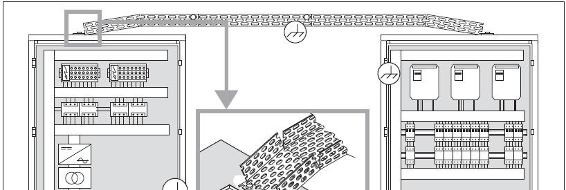
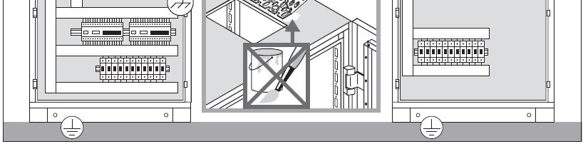
4 Comprehensive potential equalization grounding grid 1 Enclosure for power distribution Enclosure for control and measurement technology Tray for power cable Tray for low-power cable Steel reinforcement in concrete ceilings, metallic bases in false ceilings Earth connections For EMC purposes, ideally there should be low and high-frequency potential equalization between all metallic masses, enclosures, machine and system components, which should be meshed as closely as possible. 4

5 Comprehensive potential equalization routing A Power supply B Data/control connection Enclosure Cable Earth connection Reference potential Loop Enclosure Machine Measuring device Cable routing in machinery and equipment Basic principle: Avoid large cable loops; lay current-carrying cables as close as possible to the reference potential. 5


6 Comprehensive potential equalization connections L < About 2 A in 2 In practice: Maximum possible cross section, large-area conductive mounting, low-inductive (therefore, a rectangle is better than a round conductor). 6
7 Comprehensive potential equalization connections 1 Plain washer and spring lock washer 2 3 Screw connection Spring lock washer 7
8 Comprehensive potential equalization connections 8


9 Comprehensive potential equalization connections 1 Green with yellow stripe conductor 9


10 Comprehensive potential equalization connections How to connect metallic cable tray to the enclosure 1 Conductive connection 2 Contact paint provides protection against corrosion 10


11 Comprehensive potential equalization connections Conductive connection of metallic cable tray 11


12 Comprehensive potential equalization connections L < About 2 A in 2 Conductive connection of metallic cable ducts 12


13 Comprehensive potential equalization connections Conductive attachment of metallic cable trays 13


14 Comprehensive potential equalization connections L < About 2 A in 2 Conductive connection between machine and system components 14


15 Functional enclosure layout / spatial division 1 High outputs 2 Low outputs 15


16 Functional enclosure layout / spatial division 1 High outputs 2 3 Low outputs Inputs 16


17 Measures within the enclosure 1 High outputs Low outputs More powerful Components Mains Dividing area Actuators Transducers, probes, Detectors Shielded enclosures Protect sensitive assemblies by means of encapsulation, shielded case / sub rack within the enclosure 17


18 Measures within the enclosure for optimum shielding effect 1 Shielded viewing window, as small as possible Conductive seal between the enclosure and removable enclosure panels Enclosure within an enclosure Potential equalization via suitable rails or conductive mounting plate Air-conditioning apertures with RF filters Actuators Mains filter/overvoltage protection at the point of entry, with large-area contact Unshielded control cables via filter openings conductively connected to the enclosure entry point Shielded cables via EMC cable glands 18
19 Optimum potential equalization of enclosure surfaces L < About 2 A in 2 19


20 Enclosure back panel as a potential equalization surface 1 Conductive mounting plate 2 3 Long PE conductor Painted sheet metal All components with a conductive housing can be conductively mounted with a large contact area. L < About 2 A in 2 20


21 Shielding interface with the enclosure 1 5 Ideal to have all-round EMC cable glands Conductive metal sheet 2 5 EMC gland plates Conductive metal sheet 3 5 EMC shield bus Conductive metal sheet 4 5 Potential equalization on the mounting plate Conductive metal sheet Solder ring terminal Tin plated braiding Soldered earth strap Cable shields should be contacted directly at the point of cable entry, where possible. 21


22 Filters Important: Spatially separate input and output cables from one another; use as shielded cables Conductive metal sheet Control assembly Output: To actuator or machine Filter Power supply 22


23 Filters 1 Conductive metal sheet Control assembly Output: To actuator or machine Filter Power supply 23


24 Filters Conductive metal sheet Filter Power supply Important: Ensure there is large-area conductive connection between the filter housing and the mounting surface; avoid cable loops to the reference potential. 24


25 Transformers 1 Conductive metal sheet 2 Plastic material or painted Position transformers on gland plates with large-area conduction, conductive connection of the shield 25

26 Cabling rules, cable selection, and routing Immunity to interference of connected equipment Shielded, twisted cable pair Shielded, twisted cable pair with extra shielding Unused conductor Multi-conductor wire Unshielded, twisted cable pair 26


27 Cabling rules, cable selection, and routing Immunity to interference of connected equipment Unshielded multi-conductor cable Shielded multi-conductor cable Shielded multi-conductor cable, in metal conduit or in metallic cable tray 27


28 Cabling routing between panels and machine/system parts Steel conduit Steel cable tray Steel cable tray or Sheet steel supports Sheathings, open laying of bus cables etc. Surface cabling with cable clamps or other fastening components PVC plastic conduit, surface mounted 28


29 Cabling routing in tray selection / population Closed metallic cable tray Plastic cable tray Areas with effective shielding against electromagnetic fields Open metal cable tray Open metal mounting angle 29
30 Cables emission and interference sensitivity in cable trays Unshielded cable D Large as possible Immunity to Interference Interference Emission Unshielded cable Very sensitive High Shielded cable Sensitive Low 30

 2 Reference potential or potential equalization rail")

31 Potential equalization of shielded cable l= Lambda: Wavelength of the maximum frequency occurring in the vicinity 1 Reference potential (machine chassis or separate rail) 2 Reference potential or potential equalization rail with connection to the chassis Cable shield with potential equalization on one side Cable shield without potential equalization contact 31


32 Cable routing Connect unused conductor to reference potential Output Control Signals Keep cables perpendicular wherever possible, and ensure adequate distance between interference-emitting and sensitive cables. 32


33 Information from Rittal: Practical assembly tips 33
CFW PowerCable Redefining EMC. TN-S - the induction-free, low-radiation installation cable
 CFW PowerCable Redefining EMC TN-S - the induction-free, low-radiation installation cable The CFW PowerCable Patent / Design Brugg Cables Switzerland The CFW PowerCable -patent is based on a totally new
2: Stylebox Stylebox 15 Overview B 2_ Complete Stylebox 15 Kits B 2_ Stylebox 15 Standard Kit B 2_8
 2.1 Stylebox 15 Overview 2_3 2.1.1 Complete Stylebox 15 Kits 2_7 2.1.2 Stylebox 15 Standard Kit 2_8 2.2 Stylebox 15 Smart 2_10 2.2.1 Width 2_11 2.2.2 Height ezel 2_11 2.2.3 Depth 2_11 2.2.4 Top Cover Panel
PRODUCT INFORMATION BULLETIN
 724-283-4681 724-283-5939 (fax) PRODUCT INFORMATION BULLETIN DESCRIPTION The, Model 10-7100 is one in a series of critical speed switches that monitor speed and detect motion in all types of machinery
Welcome to the ABB Industrial Drives, ACS800 planning the installation training module. If you need help navigating this module, click the Help
 Welcome to the ABB Industrial Drives, ACS800 planning the installation training module. If you need help navigating this module, click the Help button in the top right corner. To view the presenter notes
P200 P/I Transducer. Installation, Operation, and Maintenance Instructions INTRODUCTION
 INTRODUCTION Scope This manual provides instructions for the installation, adjustment, maintenance, and parts ordering of the P200 Pneumatic-to-Current P/I Transducer. Due to its over-engineered design,
For air / gas dampers and control valves of oil or gas burners
 7 803 Actuators For air / gas dampers and control valves of oil or gas burners SQN13.xxxB9 SQN14.xxxB9 Electromotoric actuators Torque: Up to 1 Nm rated output torque Direction of rotation: - SQN13 Counterclockwise
EMC INSTALLATION INFORMATION
 EMC INSTALLATION INFORMATION For: SANYO DENKI Stepper Motors RTA Stepper Drives AUTOMATED MOTION SYSTEMS PTY.LTD. MAILING ADDRESS: P.O.BOX 1240 WANGARA DC W.A. 6947 PHONE: (08) 9309 1896 FAX: (08) 9309
Unified requirements for systems with voltages above 1 kv up to 15 kv
 (1991) (Rev.1 May 2001) (Rev.2 July 2003) (Rev.3 Feb 2015) (Corr.1 June 2018) Unified requirements for systems with voltages above 1 kv up to 15 kv 1. General 1.1 Field of application The following requirements
ÖLFLEX CLASSIC 110 CY
 Screened PVC control cable with transparent outer sheath - PVC control cable, VDE registered, screened, flexible and numbered for various applications, U 0 /U: 300/500V Info CPR: choice under www.lappkabel.com/cpr
Tips & Technology For Bosch business partners
 Tips & Technology For Bosch business partners Current topics for successful workshops No. 73/2013 Gasoline injection Ignition cables technical information In gasoline engines, the high voltage required
Unarmored Variable Frequency Drive (VFD) Cable Termination Guide
 Cable Termination Guide") Unarmored Variable Frequency Drive (VFD) Cable Termination Guide Be Certain with Belden A Step-by-Step Look at the Connection/Termination of Unarmored VFD Cables Terminating Unarmored Variable Frequency
Unarmored Variable Frequency Drive (VFD) Cable Termination Guide Be Certain with Belden A Step-by-Step Look at the Connection/Termination of Unarmored VFD Cables Terminating Unarmored Variable Frequency
APEX DRIVE USER GUIDE ADDENDUM: LVD INSTALLATION INSTRUCTIONS
 APEX DRIVE USER GUIDE ADDENDUM: LVD INSTALLATION INSTRUCTIONS Product Type: APEX10, APEX20 and APEX40 Servo Drives The above products are in compliance with the requirements of directives 72/23/EEC Low
STANDARD PRODUCT OVERVIEW EMC FILTERS FOR MILITARY VEHICLES STANDARD EMC FILTERS FOR MILITARY VEHICLES FILTER SELECTION PROCESS. Introduction CONTENTS
 STANDARD PRODUCT OVERVIEW EMC FILTERS FOR MILITARY VEHICLES STANDARD EMC FILTERS FOR MILITARY VEHICLES Introduction This brochure covers a standard range of cost effective MOTS (military-off-the-shelf)
Electronic Ignition Equipment
 7 608 Electronic Ignition Equipment TQG3 The TQG3 consists of a cable for connection to the safety shutoff valves of the VGU gas valves and electronic ignition equipment for use on gas boilers with single-
Grounding and Wiring of Protection and Control Equipment
 Grounding and Wiring of Protection and Control Equipment 1MRB520197-Ten Edition February 2002 p Technical Document 1997 ABB Switzerland Ltd Baden/Switzerland 2nd Edition All rights with respect to this
Product Data Sheet. Damper Interface. Features
 Damper Interface Product Data Sheet Features Damper Motor drive and limit switch monitoring integrated into a single unit Dual limit switch inputs for confirmation of damper-fully-open and damperfully-closed
Recommended Practices for Installation for EC Directive 2014/30/EU Relating to EMC
 Recommended Practices for Installation for EC Directive 2014/30/EU Relating to EMC 10/16 Supplement to Installation & Operating Manual Any trademarks used in this manual are the property of their respective
Mounting and Installation Guidelines
 I Product Marketing I Nordstrasse 11 I 4542 Luterbach I Switzerland T +41 32 681 66 26 I F +41 32 681 66 30 I www.schaffner.com Sine Wave Filter Series FN 5040, FN 5045 and FN 5040 HV Please read and follow
EMC Issues in Electric Drives
 EMC Due to: Control systems requirements. Motor operation. Physical constraints. Scaling of EMC Methods to Electric Drive Analysis. New Developments / Future Methods Why Use Electric Drives? Advances in
Ch 4 Motor Control Devices
 Ch 4 Motor Control Devices Part 1 Manually Operated Switches 1. List three examples of primary motor control devices. (P 66) Answer: Motor contactor, starter, and controller or anything that control the
Installation Instructions
 Quick-Mount Visual Instructions for Mechanical Installation Quick-Mount Visual Instructions 1. Rotate the damper to its failsafe position. If the shaft rotates counterclockwise, mount the CCW side of the
Power distribution components
 Industrial electronics Power distribution components Reliable, cost-effective, complete R England sv_001.fm Rittal power distribution components Bar centre distance (mm) Number of poles Busbar dimensions
Why Electric Safety Standards
 Paul Haggarty Why Electric Safety Standards To protect patients and caregivers from electrical shock To prevent electrical interference between instrument sub-systems/circuits To prevent electrical interference
AN-106 Rev 0, 27-Jan-17
 ACT4529M Automotive EMC Performance Abstract This application note shows that the ACT4529M passes third party testing for Automotive SAE-J1752-1 and SAE-J1752-3 EMC testing at EMI level M8A. Introduction
Candidate Handbook answers
 Candidate Handbook answers Progress check 7.1, p. 341 1. What must the electrical system installed in premises be suitable for? The purpose of the system; the building and environment. What is the role
S2005 Cabinets DESIGNERS AND MANUFACTURERS OF 19 RACK SYSTEMS
 This series of Cabinets forms the basis of Australia s top selling range. They are both aesthetically pleasing and versatile. All versions of similar height and depth may be readily bayed together, further
Installation Instructions
 Quick-Mount Visual Instructions for Quick-Mount Visual Instructions 1. Rotate the damper to its failsafe position. If the shaft rotates counterclockwise, mount the CCW side of the actuator out. If it rotates
THE NEW TS IT RACK 8
 THE NEW TS IT RACK 8 Fast and reliable Fast Loosen the 48. (9 ) quickrelease fastener, slide into the correct position, and latch Reliable Maximum load capacity up to,000 N Convenience in perfection Interior
CLP POWER HONG KONG LIMITED. SUPPLY RULES March 2001
 CLP POWER HONG KONG LIMITED SUPPLY March 2001 ADVISORY SERVICE Advice concerning matters relating to the supply of electricity may be obtained free of charge from the Company. OTHER COMPANY PUBLICATIONS
2.7. IT system floor-standing distribution cabinet Series -IPS-F
 Dipl.-Ing. W. Bender GmbH & Co. KG Londorfer Str. 65 35305 Grünberg Tel.: 0640 07-0 Fax: 0640 07-25 IT system floor-standing distribution cabinet Series -IPS-F for supplying power to medical locations
Systems. Intelligent. Power & Control. Würth Elektronik ICS. Solutions and technologies for:
 Würth Elektronik ICS Solutions and technologies for: Intelligent Power management Signal transmission Control Display and input Plug connections Power & Control Systems Würth Elektronik ICS The Würth Group
Construction and Wiring Guidelines for Ergon Energy Substation Panels
 Construction and Wiring Guidelines for Ergon Energy Substation Panels Table of Contents Purpose and Scope... 1 Responsibilities... 1 Definitions, Abbreviations and Acronyms... 1 References... 1 Panel Wiring...
- Wiring Brochure Zone Manager 335
 - Wiring Brochure W 335 12/08 1 Information Brochure Choose controls to match application 2 Application Brochure Design your mechanical applications Rough-in Wiring Rough-in wiring instructions 3 4 Wiring
Rittal CM Compact System Enclosures
 Rittal CM Compact System Enclosures Compact class = Top class: Infinite possibilities R Compact enclosure on the outside, Top enclosure on the inside! Index Convincing details... 3 5 Compact system enclosures
Corflex. Continuous Corrugated Aluminum Sheathed PL, MC and MV Industrial Cables. Introduction Applications... 3
 Corflex Continuous Corrugated Aluminum Sheathed PL, MC and MV Industrial Cables Introduction................................. 2 Applications................................. 3 Corflex PL 300V Instrumentation
Electromagnetic Flow Monitor magphant
 Technical Information TI 036D/24/ae Electromagnetic Flow Monitor magphant Flow monitoring in 1 to 80 pipes with conductive liquids Monitoring and measurement Flow monitoring with selectable limit values
Have You Been Grounded Lately
 Have You Been Grounded Lately Thurs, Oct. 26, 2017 9:15-10:15 Phil Simmons Author, Electrical Grounding and Bonding Author Cengage Learning Phil Simmons Have You Been Grounded Lately 2017 NEC Changes Relative
- Wiring Brochure Zone Manager 336
 - Wiring Brochure W 336 12/08 1 Information Brochure Choose controls to match application Application Brochure Design your mechanical applications 2 3 Rough-in Wiring Rough-in 4 Wiring Brochure Wiring
Application Note EMC - Checklist
 Application Note EMC - Checklist A checklist to avoid EMC trouble General 100151 Title... EMC - Checklist Version... 1.10 Document no.... 100151 Original...en Author... Festo Last saved... 08.08.2017 Copyright
VIS IRREVERSIBLE ELECTROMECHANICAL MOTOR FOR SECTIONAL DOORS. Rev /2011 RT
 VIS GB IRREVERSIBLE ELECTROMECHANICAL MOTOR FOR SECTIONAL DOORS. Rev. 01-07/2011 RT TECHNICAL DATA LIFE home integration reserves the right to change the specifications at any time without notice, maintaining
CP-1TT Remote System
 CP-1TT Remote System (9 volt & 12 volt systems) INSTALLATION/OPERATION MANUAL Manufactured by: Preferred Technologies Group www.cartell.com TABLE OF CONTENTS This Table of Contents is clickable. Point
Implementation of low inductive strip line concept for symmetric switching in a new high power module
 Implementation of low inductive strip line concept for symmetric switching in a new high power module Georg Borghoff, Infineon Technologies AG, Germany Abstract The low inductive strip line concept offers
OPERATING INSTRUCTION
 11/05 Form #273 OPERATING INSTRUCTION MODEL 4105 Disital Earth Resistance Tester 2150 joshua's Path, Suite 302, Hauppauge, NY 11788 Phone : 1-800-645-5398 or 1-639-231-7050 Fax : 1-639-434-3128 E-mail
Technical Documentation
 Technical Documentation Product manual Holding brake controller Document: 0198441113316 Edition: V1.00, 03.2006 Important information The drive systems described here are products for general use that
Current Carrying Capacity of RADOX Solar cables
 Current Carrying Capacity of RADOX Solar cables Content: 1. Scope 2 2. Definitions 2 3. General remarks 2 4. Current rating under service conditions 3 4.1 Standard conditions for current rating 3 4.2 Reduction
Preparing the Site. Information About the Site Requirements CHAPTER
 2 CHAPTER This chapter describes the basic site requirements that you should be aware of as you prepare to install your Cisco Nexus 7000 Series switches. This chapter includes the following sections: Information
INSTALLATION INSTRUCTIONS
 INSTALLATION INSTRUCTIONS WARNING: WARNING: www.altronicinc.com DEVIATION DEVIATION FROM THESE FROM INSTRUCTIONS THESE INSTRUCTIONS MAY LEAD MAY TO LEAD IMPROPER TO IMPROPER OP- ERATION OF ENGINE THE MACHINE
Actuators for air dampers and control valves of oil burners
 7 812 Actuators for air dampers and control valves of oil burners SQM1... SQM2... Reversible electromotoric actuators Torques: - SQM1... up to 10 Nm - SQM2... up to 20 Nm Running times: - SQM1... 14...100
SITRANS AS 100. Instruction Manual September 2001 ITRANS AS 100
 SITRANS AS 100 Instruction Manual September 2001 ITRANS AS 100 Safety Guidelines Warning notices must be observed to ensure personal safety as well as that of others, and to protect the product and the
For air dampers and control valves of oil or gas burners
 7 813 Actuators For air dampers and control valves of oil or gas burners SQM33... Electromotoric actuators Torques: - SQM33.4 up to 1.2 Nm nominal output torque - SQM33.5 up to 3 Nm nominal output torque
Servo-pneumatic drive solution for welding guns. Top quality welding!
 Servo-pneumatic drive solution for welding guns Sturdy and precise! Top quality welding! Highlights Extremely short cycle times High quality and outstanding reproducibility of the spot welds Excellent
06. har-mik INTERFACE CONNECTORS
 . INTERFACE CONNECTORS Miniature D connectors are a must in various cableto-board applications where space saving and high data transfer rates are required. For the purposes of miniaturization and speed,
MECKLENBURG COUNTY. Land Use and Environmental Service Agency Code Enforcement 2/8/12 ELECTRICAL CONSISTENCY MEETING. Code Consistency Questions
 MECKLENBURG COUNTY Land Use and Environmental Service Agency Code Enforcement 2/8/12 ELECTRICAL CONSISTENCY MEETING Code Consistency Questions 1. I am inspecting a building addition. They have a 480V to
Rotary Position Transducers
 Rotary Position Transducers E8R-RL210-G01MC E8R-RL210-G011S Instruction & Operation Manual Sales / Service / Support 363 St. Paul Blvd. Carol Stream, IL 60188 Tel: (630)610-7171 FAX: (630)668-4676 Application
LTX RF LEVEL SENSOR. Instruction Manual
 LTX RF LEVEL SENSOR Instruction Manual FOR MODELS LTX01, LTX02, LTX05 Intempco Document No: LTX - M01 Rev. 1 Issue Date: April 2005 LTX01 RF LEVEL SENSOR USER MANUAL Software Rev : Rev. Date : June 2004
c. Single battery installations must comply with the 18 inch envelope for dielectric
 1. Which of the following is a true statement? a. Multiple battery installations must comply with the 12 inch envelope for dielectric shielding when required. b. Multiple battery installations must comply
LB - LIGHTING BUSWAY 25-40A
 16 LB - LIGHTING BUSWAY 25-40A LIGHTING BUSWAY SECTION CONTENTS 18 General features 24 Trunking components: 2 and 4 conductors elements 28 Trunking components: 6 conductors elements 30 Plugs 33 Fixing
Paddle Wheel Turbine Flow Meters Installation, Operating & Maintenance Manual
 COMPANY Paddle Wheel Turbine Flow Meters Installation, Operating & Maintenance Manual Mechanical Specifications Flow Meter with Polypropylene Body (ES version) Maximum Operating Pressure: 150 PSIG Maximum
CRegulatory. Compliance: UL and CE APPENDIX C IN THIS CHAPTER. Installation Instructions Installation Guidelines System Installation Techniques
 APPENDIX C CRegulatory Compliance: UL and CE IN THIS CHAPTER Installation Instructions Installation Guidelines System Installation Techniques Appendix C Regulatory Compliance: UL and CE 81 Regulatory Agencies
Unidrive M400 Fast set-up and diagnostics with real-text display, integrated PLC and safety inputs
 Unidrive M400 Fast set-up and diagnostics with real-text display, integrated PLC and safety inputs 0.25 kw - 110 kw (0.33 hp - 150 hp) 100 V 200 V 400 V 575 V 690 V Unidrive M400 features Optional AI-485
Revision to the Catalog and to the Operating Instructions , , ,
 Drive Technology \ Drive Automation \ System Integration \ Services Revision to the Catalog 16890426 and to the Operating Instructions 16889614, 16889215, 16888812, 16876016 Mechatronic Drive System MOVIGEAR
5. Installation on Pedestal - IP 21 / IP 54 Units 43
 Contents Contents 1. General Information 3 2. Preinstallation 7 Planning the Installation Site 7 Receiving the Frequency Converter 7 Transportation and Unpacking 7 Lifting 8 Shipping Weights and Dimensions
DEPARTMENT OF DEFENSE STANDARD PRACTICE IDENTIFICATION CODING AND APPLICATION OF HOOKUP AND LEAD WIRE
 NOTICE OF CHANGE INCH-POUND MIL-STD-681D NOTICE 1 19 June 2000 DEPARTMENT OF DEFENSE STANDARD PRACTICE IDENTIFICATION CODING AND APPLICATION OF HOOKUP AND LEAD WIRE TO ALL HOLDERS OF MIL-STD-681D: 1. THE
MODEL 8682 SUREFLOW ADAPTIVE OFFSET CONTROLLER
 MODEL 8682 SUREFLOW ADAPTIVE OFFSET CONTROLLER INSTALLATION INSTRUCTIONS WARNING: The Model 8682 Adaptive Offset Controller must be wired to 24 VAC only. Wiring the unit to 110 VAC will cause serious unit
ABB POWER SYSTEMS CONSULTING
 ABB POWER SYSTEMS CONSULTING DOMINION VIRGINIA POWER Offshore Wind Interconnection Study 2011-E7406-1 R1 Summary Report Prepared for: DOMINION VIRGINIA POWER Report No.: 2011-E7406-1 R1 Date: 29 February
Knürr Smaract. Knürr Smaract. CompactRack
 CompactRack Features Ample space for components and cabling provided in an efficient, compact design. The innovative frame concept with triangular extrusions ensures low weight while maintaining high stability.
GMM. Intelligence for condensers and drycoolers with AC fans. Güntner Info. sincon
 GMM sincon Güntner Info Güntner Motor Management for AC fans with frequency converter and all-pole sine filter Intelligence for condensers and drycoolers with AC fans GMM sincon Güntner Motor Management
Ethernet Buccaneer BUCCANEER DATA. bulgin
 BUCCANEER FOR DATA bulgin Coupling ring, screw thread provides secure cable coupling Shroud for RJ45 provides protection against damage through mis-use and positive alignment for mating of Panel maintains
ABB ACTUATORS & POSITIONERS
 ABB ACTUATORS & POSITIONERS ABB INTELLIGENT POSITIONERS PositionMaster EDP300 - Digital Positioner Analog HART communication Universal analogue input Operation with air, optional with Graphical display
Actuators for air dampers and control valves of oil burners
 7 812 Actuators for air dampers and control valves of oil burners SQM1... SQM2... Reversible electromotoric actuators Torques: - SQM1... up to 10 Nm - SQM2... up to 20 Nm Running times: - SQM1... 14...100
The range is fully compatible with the PS system accessories.
 The ES 5000 exclusive enclosure the compact enclosure system with multiple benefits Compact for electronics, ideal for machine control, generously proportioned for climate control, flexible and cost-effective
Paddle Wheel Turbine Flow Meters Installation, Operating & Maintenance Manual
 COMPANY Paddle Wheel Turbine Flow Meters Installation, Operating & Maintenance Manual 2016 AW-Lake Company. All rights reserved. Doc ID:PADDLEMAN082416 Mechanical Specifications Flow Meter with Polypropylene
Rated Current. Test Voltage
 SINGLE POLE HIGH VOLTAGE CONNECTORS 10 / 20 / 30 / 40kV FEATURES Up to 40kVDC / 30A 100,000 Mating Cycles UL94 V-0 Flammability Rating Extended Temperature Range Central Attachment Low Cost Made in Germany
Ultrasonic Two-Wire Point Level Control
 Ultrasonic Two-Wire Point Level Control General Instructions The Ultrasonic Point Level Control indicates liquid presence/absence within a sensor cavity. Two piezoelectric crystals face each other across
Tender Schedule. Sl. No. Particulars Quantity Unit Rate `
 Tender Schedule Estimate for Electrical Works at Savalyapuram Branch(18901) Guntur(District). Sl. No. Particulars Quantity Unit Rate ` 1 Wiring for light point/ fan point/ exhaust fan point/ call bell
A driving force in the market place
 A driving force in the market place Since 1973 Mettex has been producing quality, well engineered and affordable flexible braided wire products for use throughout the electrical industries. We are now
ME 463 Electronics Design
 ME 463 Electronics Design Following this procedure will help the e-shop personnel assist you to (1) improve the quality and viability of the electrical part of your project, and (2) increase the safety
SUM340 SUMMATION BOARD
 Capricorn Controls Data & Application Note Page 1 of 6 SUM340 SUMMATION BOARD Genset Controls - Timers/Monitors/Trips - Battery Charging Spares & Accessories - Custom Products The SUM340 Summation Board
Generator Termination Bus-bar Arrangement - Design requirements: Utility Perspective
 Generator Termination Bus-bar Arrangement - Design requirements: Utility Perspective D. K. Chaturvedi (NTPC) Harshvardhan Senghani (NTPC) K Venugopal (CS Electric) This paper appraise user on the termination
Sentinel Field Satellite Controller
 WARNING HIGH VOLTAGE 115V M AP Sentinel Field Satellite Controller Installation Instructions Important: For your protection and the safety of the product user, please comply with all Caution and Warning
Choose the future Choose
 Choose the future Choose PEDCALL AND AUDIO TACTILE SYSTEM Robust design Auto pedestrian detection Vandal resistant Proven field performance Safe The BRAUMS Pedestrian (Push Button) Detector (PEDCALL) and
My Reserve 500 Install Guide
 My Reserve 500 Install Guide System Overview Diagram Warnings Disclaimer of Liability and Warranty: This guide does not replace the Owner s Guide and Installation Instructions supplied with the components.
Ethernet Buccaneer IP68 BUCCANEER FOR DATA BUCCANEER DATA
 IP68 Coupling ring, screw thread provides secure cable coupling Shroud for RJ45 provides protection against damage through mis-use and positive alignment for mating of Panel maintains IP68 seal to panel
Zucchini Low-Medium Power
 Zucchini Low-Medium Power High Power CATALOGUE 2010 CATALOGUE 2010-2011 ZHP08C/GB Coordination table with Legrand DPX MCCBs SL, MS, SB, MR Switch-Busbar coordination table. Contingent short circuit ka
PART 10 ELECTRICAL INSTALLATIONS
 PART 10 ELECTRICAL INSTALLATIONS SECTION SUBJECT 10.1 General 10.2 Cables 10.3 DC systems 10.4 Batteries 10.5 AC systems 10.6 Earthing and bonding 10.7 Motor control 10.8 Lighting 10.9 Remote stops 10.10
MATERIAL FOR FIBRE OPTIC LINES. General C-bracket HSU trunnion type, forged, for aluminium based OPGW conductors...
 153 Contents General.................................................................................................. 154 C-bracket.................................................................................................
Electric expansion valve Type ETS ETS 400
 Data sheet Electric expansion valve Type ETS 12.5 - ETS 400 ETS is a series of electric expansion valves for precise liquid injection in evaporators for air conditioning and refrigeration applications.
Pipe Shield High-Voltage Wiring Harness
 World Electric Vehicle Journal Vol. 5 - ISSN 2032-6653 - 2012 WEVA Page 0581 EVS26 Los Angeles, California, May 6-9, 2012 High-Voltage Yoshio Mizutani 1, Oliver Weiss 2 1 Hybrid Vehicle R&D Div., AutoNetworks
ENERGY. TECWATER EMV-FC S1BC4N8-F 0,6/1 kv. Screened Cable for Water Application
 ENERGY TECWATER EMV-FC S1BC4N8-F 0,6/1 kv Screened Cable for Water Application Technical Data Trademark Type designation Specification Application TECWATER EMV-FC S1BC4N8-F Design and tests according to
PRODUCT INFORMATION. UNITRONIC LiYCY. Benefits Overall shield minimises electrical interference Versatile application possibilities
 Shielded data cable with colour code according to DIN 47100 - shielded PVC data cable with colour code DIN 47100 for use in machinery and apparatus construction and in measurement, control and regulation
GROUNDING & BONDING PRODUCTS
 GROUNDING & BONDING PRODUCTS Busbars Page 5-3 Insulators Page 5-8 Grounding Products Page 5-9 Compression Tools, Lugs & Taps Page 5-14 Learn About CPI s Extended Limited Warranties for coverage of (2)
SECTION 15. GROUNDING AND BONDING
 9/27/01 AC 43.13-1B CHG 1 SECTION 15. GROUNDING AND BONDING 11-185. GENERAL. One of the more important factors in the design and maintenance of aircraft electrical systems is proper bonding and grounding.
Magnetic Proximity Switch MSW-L (Latching Type) DC/AC Version CE Classification: M2C235AU9
 DC/AC Version CE Classification: M2C235AU9") SYGNATECH,INC. 3215 Golf Rd, #266, Delafield, WI 53018 USA Phone: (262) 646-2464 Fax: (262) 646-2392 Magnetic Proximity Switch MSW-L (Latching Type) DC/AC Version CE Classification: M2C235AU9 SYG.MSWL/man11,
SYGNATECH,INC. 3215 Golf Rd, #266, Delafield, WI 53018 USA Phone: (262) 646-2464 Fax: (262) 646-2392 Magnetic Proximity Switch MSW-L (Latching Type) DC/AC Version CE Classification: M2C235AU9 SYG.MSWL/man11,
SP2 Options Installation and Maintenance Instructions
 3439152/2 IM-P343-22 CH Issue 2 SP2 Options Installation and Maintenance Instructions 50% SP2 1 2 3 4 5 General safety information Options Electrical connections Programming and commissioning travel switches
3-way servo solenoid valves, cartridge type, pilot operated, with inductive position transducer
 3-way servo solenoid valves, cartridge type, pilot operated, with inductive position transducer Type 3WRCB 25...50 Nominal size (NG) 25, 32, 50 Unit series 1X Maximum working pressure P, A, T, X, Z 315
Level Measurement Point level measurement - RF Capacitance switches
 Pointek CLS200 - Standard Overview Configuration Installation Pointek CLS200 (standard version) is a versatile inverse frequency shift capacitance level and material detection switch with optional rod/cable
General Information... Temperature/Resistance Table... Part Numbering Examples for RTD s. High Temperature MgO Elements (RA)...
...") Page General Information... Temperature/Resistance Table... Part Numbering Examples for RTD s High Temperature MgO Elements (RA).... Leadwire Style RTD s (RB).. Leadwire Style RTD s (RD, RE, RF, or RG
Page General Information... Temperature/Resistance Table... Part Numbering Examples for RTD s High Temperature MgO Elements (RA).... Leadwire Style RTD s (RB).. Leadwire Style RTD s (RD, RE, RF, or RG
TECHNICAL GUIDE FOR PROXIMITY SENSORS DEFINITIONS YAMATAKE PROXIMITY SENSOR CATEGORIES
 TECHNICAL GUIDE FOR PROXIMITY SENSORS DEFINITIONS "" includes all sensors that detect the presence of a metallic object approaching the sensing face or near the sensing face without mechanical contact.
Operating Instructions
 Operating Instructions Pendant Light Fitting > Contents 1 Contents 1 Contents...2 2 General Information...2 3 General Notes Regarding Safety...3 4 Intended Area of Application...4 5 Technical Data...5
AUTOMOTIVE EMC TEST HARNESSES: STANDARD LENGTHS AND THEIR EFFECT ON RADIATED EMISSIONS
 AUTOMOTIVE EMC TEST HARNESSES: STANDARD LENGTHS AND THEIR EFFECT ON RADIATED EMISSIONS Martin O Hara Telematica Systems Limited, Trafficmaster, University Way, Cranfield, MK43 0TR James Colebrooke Triple-C