Air Filter Element, Replacing and Cleaning Housing
|
|
|
- Preston Bishop
- 6 years ago
- Views:
Transcription
1 Air Filter Element, Replacing and Cleaning Housing Note Only use silicone-free lubricant for assembling the intake hoses. Secure all hose connections with hose clamps that match current standard production. Refer to the Parts Catalog. Chapter Air Filter Housing, Cleaning. Chapter 6-Cylinder Gasoline Engine 3.0L TFSI. Chapter 6-Cylinder Diesel Engine 3.0L TDI. 6-Cylinder Gasoline Engine 3.0L TFSI Special tools and workshop equipment required Torque Screwdriver -VAS6494-, measuring range: 1.5 to 3 Nm Or: Torque Screwdriver -VAG1624-, measuring range 1 to 5 Nm Tightening Specification Table for Installation: Component / Fastening Element: [Nm] Air filter element screw 3.5 Step 1 - Air Filter Element, Removing: Open the clamp -arrow B-. Remove the air filter upper section -1- from the retaining pin -arrow A- and remove.


2 Remove the bolt -1-. Remove the air filter element on the retainer -2- from the catches in the direction of the -arrow-. Step 2 - Air Filter Element, Installing Check the housing and water drains for dirt and clean them if necessary. Refer to Chapter Air Filter Housing, Cleaning. Align the new air filter element -13- to the air filter lower section catches -17- and push in the catches. Install the bolt -14- in the air filter element and tighten to the tightening specification (Tightening Specification

3 Table for Installation, Refer to Anchor). Additional installation procedures occur in reverse order. Make sure that the air filter upper section seals tightly with the air filter lower section. 6-Cylinder Diesel Engine 3.0L TDI Special tools and workshop equipment required Torque Screwdriver - VAS6494-, measuring range: 1.5 to 3 Nm Or: Torque Screwdriver - VAG1624-, measuring range 1 to 5 Nm Tightening Specification Table for Installation: Component / Fastening Element: [Nm] Air filter element screw 3.5 Step 1 - Air Filter Element, Removing: Open the clamp -arrow B-. Remove the air filter upper section -1- from the retaining pin -arrow A- and remove.
4 Remove the bolt -1-. Remove the air filter element on the retainer -2- from the catches in the direction of the -arrow-. Step 2 - Air Filter Element, Installing Check the housing and water drains for dirt and clean them if necessary. Refer to Chapter Air Filter Housing, Cleaning. Align the new air filter element -10- to the air filter lower section catches -14- and push in the catches. Install the bolt -11- in the air filter element and tighten to the tightening specification (Tightening Specification
.")
5 Table for Installation. Refer to Anchor). Additional installation procedures occur in reverse order. Make sure that the air filter upper section seals tightly with the air filter lower section. Air Filter Housing, Cleaning Procedure: Remove any loose dirt residue and leaves from the air filter housing (upper and lower sections). Check the water drain hose in the air filter lower section for dirt and adhesives, and clean if necessary. Note When cleaning the air filter housing with compressed air, observe the following: cover the Mass Airflow Sensor with a clean cloth. In countries with cold climates, the snow screen must also be cleaned in the intake line. Observe the specification in the Fluid Capacity Tables; Rep. Gr.03.

6 Engine Oil Filter, Replacing Chapter 6-Cylinder Gasoline Engine 3.0L TFSI. Chapter 6-Cylinder Diesel Engine 3.0L TDI. 6-Cylinder Gasoline Engine 3.0L TFSI Special tools and workshop equipment required Torque Wrench Nm -VAG1331-, measuring range: 6 to 50 Nm Or: Electronic Torque Wrench 3-60Nm -VAS6583-, measuring range 3 to 60 Nm Socket -36 mm- Tightening Specification Table for Installation: Component / Fastening Element [Nm] Cap 25 Procedure: Loosen the cap -arrow- on the oil filter with the Socket -36 mm-. Doing this opens the valve. Wait a short while so that the engine oil can flow out of the filter housing and into the crankcase. Remove the cap completely. Make sure that no engine oil drips onto the engine. Remove the oil filter element -2- and the seal -3- from the cap -4-. Clean the sealing surfaces on the cap -4-. Lubricate the new seal -3- with engine oil and insert. Insert the new oil filter element -2- into the cap. Install the cap -4- in the oil filter housing -1- and tighten

7 with the Socket -36 mm- to the tightening specification. Refer to Anchor. (tightening specification table for installation). 6-Cylinder Diesel Engine 3.0L TDI Special tools and workshop equipment required Torque Wrench Nm -VAG1331-, measuring range: 6 to 50 Nm Or: Electronic Torque Wrench 3-60Nm -VAS6583-, measuring range 3 to 60 Nm Socket -36 mm- Tightening Specification Table for Installation: Component / Fastening Element [Nm] Cap 35 Removal Procedures: Remove the air filter housing. Refer to Rep. Gr.23. Procedure: Loosen the cap -arrow- on the oil filter with the Socket -36 mm-. Doing this opens the valve. Wait a short while so that the engine oil can flow out of the filter housing and into the crankcase. Remove the cap completely. Make sure that no engine oil drips onto the engine.

8 Remove the oil filter element -5- and seal -6- from the cap -7-. Clean the sealing surfaces on the cap -7-. Lubricate the new seal -6- with engine oil and insert. Insert the new oil filter element -5- into the cap. Install the cap -7- in the oil filter housing -2- and tighten with the Socket -36 mm- to the tightening specification. Refer to Anchor (tightening specification table for installation). Additional installation procedures occur in reverse order.
9 Engine Oil, Extracting Chapter All Expect 6-Cylinder Diesel Engine 3.0L TDI. Chapter 6-Cylinder Diesel Engine 3.0L TDI. All Expect 6-Cylinder Diesel Engine 3.0L TDI Special tools and workshop equipment required Used Oil Collection and Extraction Unit - SMN Procedure: Pull the oil dipstick or plug out of the guide tube. Guide the oil extraction device extraction probe into the guide tube. Use a flexible extraction probe with the largest possible diameter and guide it in without using great force. Otherwise, the tip can get deflected at the bottom of the oil pan, causing a large amount of used engine oil to remain in the engine. Extract all of the engine oil. Observe the operating instructions for the extraction device. Then install the oil dipstick or plug. Note Perform the oil change at operating temperature. Follow all disposal regulations. Pay attention to cleanliness. 6-Cylinder Diesel Engine 3.0L TDI Special tools and workshop equipment required Used Oil Collection and Extraction Unit - SMN Removal Procedures: Remove the air filter housing. Refer to Rep. Gr.23. Procedure: Pull the oil dipstick or plug out of the guide tube. Guide the oil extraction device extraction probe into the guide tube. Use a flexible extraction probe with the largest possible diameter and guide it in without using great force. Otherwise, the tip can get deflected at the bottom of the oil pan, causing a large amount of used engine oil to remain in the engine. Extract all of the engine oil. Observe the operating instructions for the extraction device.
10 Then install the oil dipstick or plug. Additional installation procedures occur in reverse order. Note Perform the oil change at operating temperature. Follow all disposal regulations. Pay attention to cleanliness.


11 Noise Insulation, Removing and Installing, Front Removing Remove the bolts -1, 2, 4-. Remove the front noise insulation -3-. Installing Install in reverse order of removal and note the following: Vehicles with Parking Heater: The rubber grommet -A- must be without tension in the noise insulation -B- and the exhaust pipe must be flush with the rubber grommet -A- or hang slightly out of the rubber grommet -A-. The mouth of the exhaust pipe -C- must be installed when passing through in the sound enclosure -B- installed grommet -A- right-angled to the sound enclosure -B-. The exhaust pipe opening -C- must not point in the direction of travel -arrow- (or else the driving wind from a moving vehicle could cause an increased counter pressure in the exhaust system). Tightening Specifications Refer to Chapter Overview - Noise Insulation

12 Overview - Noise Insulation 1 - Bolt 6 Nm Quantity: Front Noise Insulation There are different versions. Refer to the Parts Catalog. Removing and Installing. Refer to Chapter Noise Insulation, Removing and Installing, Front. 3 - Bolt 2.5 Nm Quantity: Rear Noise Insulation There are different versions. Refer to the Parts Catalog. Removing and Installing. Refer to Chapter Noise Insulation, Removing and Installing, Rear. 5 - Expanding Rivet 6 - Left Noise Insulation Removing and Installing. Refer to Chapter Noise Insulation, Removing and Installing, Left. 7 - Nut 2.5 Nm Quantity: Bolt 2.5 Nm Quantity: Bolt 2.5 Nm Quantity: 4

13 Overview - Oil Pan/Oil Pump Note If large quantities of metal shavings or abraded material are detected during engine repairs, it may mean the crankshaft or connecting rod bearings are damaged. To prevent damage, perform the following steps after completing the repair; carefully clean the oil channels and replace the oil spray jets, the oil cooler and the oil filter. Oil capacities, oil specifications and viscosity classes. Refer to Fluid Capacity Tables; Rep. Gr.03 Oil spray jet for piston cooling. Refer to Fig. Oil Spray Jet for Piston Cooling. 1 - Oil Level Thermal Sensor -G266- Removing and installing. Refer to Chapter Oil Level Thermal Sensor -G266-, Removing and Installing. 2 - Gasket Replace after removing 3 - Bolt Replace after removing Tightening specification and sequence. Refer to Fig. Oil Pan Lower Section - Tightening Specification and Sequence. 4 - Oil Pan Lower Section Removing and installing. Refer to Chapter Oil Pan Lower Section, Removing and Installing. 5 - Bolt 9 Nm 6 - Lower Oil Baffle 7 - Bolt Replace after removing Tightening specification and sequence. Refer to Fig. Oil Pan Upper Section - Tightening Specifications and Sequence. 8 - Oil Pan Upper Section Removing and installing. Refer to Chapter Oil Pan Upper Section, Removing and Installing.
14 9 - Alignment Sleeve Quantity: Upper Oil Baffle 11 - Bolt 3 Nm Seal Replace after removing Install with locking compound. Refer to the Parts Catalog for the locking compound. Insert into guide frame Replace after removing 13 - Oil Pump Input Shaft 14 - O-Ring Replace after removing 15 - Sleeve Quantity: Mounting Bracket 17 - Bolt 9 Nm 18 - Chain Sprocket for Oil Pump Can only be placed onto drive axle in one position 19 - Bolt 3 Nm O-Ring 21 - Seal 22 - Oil Pump 23 - Bolt Replace after removing Replace after removing Replace after removing Do not disassemble Removing and installing. Refer to Chapter Oil Pump, Removing and Installing. 20 Nm 24 - O-Ring 25 - Bolt Replace after removing 9 Nm 26 - Intake Tube For the oil pump

15 27 - Gasket Replace after removing 28 - Oil Drain Plug 29 - Nut 30 Nm 9 Nm Oil Pan Lower Section - Tightening Specification and Sequence Note Replace the bolts that were tightened with an additional turn after removing them. Tighten the bolts in stages as follows: Step Tightening Specification/Additional Turn 1. 8 Nm diagonally 2. in a diagonal sequence, turn an additional 90 Oil Pan Upper Section - Tightening Specifications and Sequence Then tighten the bolts -1 through 6- in a diagonal sequence in stages to 20 Nm:
16 Engine Oil, Filling Caution Pressing the accelerator pedal too soon after the oil change damages the engine. Run the engine in idle as long as the indicator lamp for engine oil pressure in the instrument cluster is turned on. Only increase the RPM when the indicator lamp goes out. Special tools and workshop equipment required Filling Aid for Engine Oil -VAS6842- Refer to the Fluid Capacity Tables; Rep. Gr.03 for engine-specific oil capacities and standards. Procedure: Fill the engine oil using the -VAS Then check the oil level and correct if necessary. Refer to Chapter Engine Oil Level, Checking and Correcting if Necessary.
17 Engine Oil Level, Checking and Correcting if Necessary Oil Level, Checking using Oil Level Display in MMI. Refer to Chapter Oil Level, Checking using Oil Level Display in MMI. Caution Risk of damaging the catalytic converter when the engine oil level is too high! Drain the engine oil until the specified level is reached. Test Conditions for all Engines except for V6 Diesel Engines Engine oil temperature must be at least 60 C (140 F). After switching off the engine, wait a few minutes so that the oil can flow back into the oil pan. Vehicle must be at a level position. Test Conditions for V6 Diesel Engines: Warm engine oil temperature at 90 C (194 F). After stopping the engine, wait a few minutes to allow oil to flow back into oil pan. Vehicle must be at a level position. Oil Level, Checking using Oil Level Display in MMI Procedure: If necessary, close the hood. Turn on the ignition and activate the MMI. Select the MENU function button. Select»vehicle«. Select the left control button and follow the following menu structure. Service & Checking Oil Level Read and determine the oil level in the display. If necessary, adjust the oil level:

18 Oil Level at max near max clearly under max Evaluation / Action Drain the oil until the optimal oil level is reached. Oil level is optimal. Add engine oil until the optimal oil level is reached. While doing so, close the hood to update the oil level display. Note If the hood is open, the oil level display will not be updated in the MMI. If underfilled, a warning lamp is displayed in the driver information system.

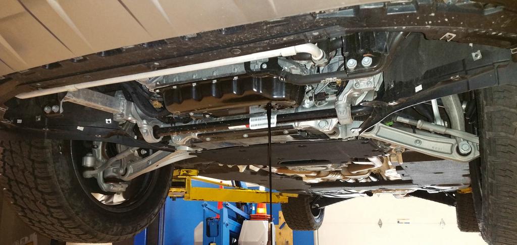
19 The Bolts Around The Sides Are Quarter Turn These Two Bolts Are Torx And Have To Be Unscrewed
20
9/24/2017 Camshaft Timing Chain Removal and Installation Engine Mechanical 2002 Audi A6/S6/Quattro/Allroad MotoLogic
 2002 A6/S6/Quattro/Allroad The information in this article comes from a service manual containing information that applies to the following engine code: BAS. Section Info: Report a problem with this article
Volkswagen New Beetle 1.8 Liter 4-Cyl. 5V Turbo OBD II Engine Mechanical 17 Engine-Lubrication system (Page GR-17)
") 17 Engine-Lubrication system (Page GR-17) Lubrication system components, removing and installing Oil pressure and oil pressure switch, checking Sump, removing and installing Valve gear, servicing (Page
17 Engine-Lubrication system (Page GR-17) Lubrication system components, removing and installing Oil pressure and oil pressure switch, checking Sump, removing and installing Valve gear, servicing (Page
Lubrication system components, removing and installing
 17-1 Lubrication system components, removing and installing Note: If large quantities of metal particles or other deposits (caused, for example, by partial seizure of the crankshaft or conrod bearings)
Camshaft. vw-wi://rl/v.en-us.k wi:: xml?xsl=3. Special tools and workshop equipment required
 Page 1 of 9 Camshaft Special tools and workshop equipment required Diesel Injection Pump Locking Pin -3359- Counterhold - Camshaft Gear -T10051- Puller - Camshaft Sprocket -T10052- Camshaft Fitting Tool
Volkswagen New Beetle 2.0 Liter 4-cyl General, Engine (Engine Code AEG) 13 Engine-Crankshaft, Cylinder block (Page GR-13)
 13 Engine-Crankshaft, Cylinder block (Page GR-13)") 13 Engine-Crankshaft, Cylinder block (Page GR-13) Engine, disassembly and assembly 10-222 A/21 guide from 10-222 A support tool, modifying Ribbed belt, removing and installing Semi-automatic toothed belt
13 Engine-Crankshaft, Cylinder block (Page GR-13) Engine, disassembly and assembly 10-222 A/21 guide from 10-222 A support tool, modifying Ribbed belt, removing and installing Semi-automatic toothed belt
Lubrication system components
 17-1 Lubrication system components If you find metal shavings or large quantities of metal particles (possibly caused by partial seizure of crankshaft and connecting rod bearings) in the engine oil while
gas passes through baffle plates in cylinder oil separator inlet port. Separated oil returns The first separation will happen when blowby
 2 05 LAYOUT AND OVERVIEW Lubrication System PCV Oil Separator Cylinder head cover (oil + gas) Blow-by gas (air duct hose) Inlet port Oil (oil gauge pipe) The first separation will happen when blowby gas
Cooling system components, removing and installing
 19-1 Cooling system components, removing and installing Note: When the engine is warm the cooling system is under pressure. If necessary release pressure before starting repair work. Hoses are secured
Direct Shift Gearbox (DSG) Mechatronic unit J743, removing and installing. - Loosen bolts - arrows - of oil pan - A - in diagonal sequence and remove.
 Mechatronic unit J743, removing and installing. - Loosen bolts - arrows - of oil pan - A - in diagonal sequence and remove.") - Loosen bolts - arrows - of oil pan - A - in diagonal sequence and remove. Note: Some transmission oil remains in the oil pan because not all of it can drain out. - Remove oil pan together with oil pan
- Loosen bolts - arrows - of oil pan - A - in diagonal sequence and remove. Note: Some transmission oil remains in the oil pan because not all of it can drain out. - Remove oil pan together with oil pan
Removing and installing trim panel
 Removing and installing trim panel vw-wi://rl/a.en-gb.a03.5106.29.wi::31914802.xml?xsl=3 1. oldal, összesen: 1 oldal Removing and installing trim panel Removing Carefully prise out trim panel -1- in direction
Cylinder head, removing and
 Page 1 of 35 15-2 Cylinder head, removing and installing Note: Replace cylinder head bolts. Always replace self-locking nuts, bolts as well as gaskets and O-rings. After installing a replacement cylinder
Lubrication system components, removing and installing
 Page 1 of 33 17-1 Lubrication system components, removing and installing WARNING! Do not re-use any fasteners that are worn or deformed in normal use. Some fasteners are designed to be used only once,
Checking and correcting ATF level
 Page 1 of 5 Checking and correcting ATF level Special tools and workshop equipment required Vehicle diagnostic tester Used oil collection and extraction unit - V.A.G 1782- Adapter for oil filling -VAS
3/6/2017 Timing Chain Service and Repair, Removal and Replacement: Valve Timing, Installing and Adjusting
 Valve timing, adjusting Special tools and equipment - T10068 Camshaft bar - T10069 Counter support - VAG 1331 Torque wrench (5-50 Nm) - VAG 1332 Torque wrench (40-200 Nm) - AMV 174 004 01 Sealing compound
Release the electrical wire from the bracket -2- toward the left -A- and remove.
 Page 1 of 8 Front Brake Pads, FBC-60, Removing and Installing Always replace on both axles. Special tools and workshop equipment required t Torque Wrench 5 50 Nm -V.A.G 1331- t Reversible Ratchet -V.A.G.
Repair Manual 11/99 PS-34. Page 1
 Repair Manual /99 PS-4 Page Table of contents Index Technical Data page Special tools 4 Repair instructions, general 0 Chain brake 6 0 Centrifugal clutch 8 0 Oil pump 9-04 Ignition system - 0 Starting
DISASSEMBLY. Engine. CAUTION: Remove the cylinder heads before removing the crankshaft. Failure to do so can result in engine damage.
 303-01A-1 DISASSEMBLY Engine Special Tool(s) Remover, Crankshaft Vibration Damper 303-101 (T74P-3616-A) Special Tool(s) Crankshaft Socket 303-674 303-01A-1 Remover, Crankshaft Vibration Damper 303-773
Drained coolant must be stored in a clean container for disposal or reuse.
 Cooling System, Draining and Filling Special tools, testers and auxiliary items required Adapter (V.A.G 1274/8) Adapter V.A.G 1274 tester (V.A.G 1274/10) Hose clamp pliers (V.A.G 1921) Cooling system charge
2003 Volkswagen Passat GL
 2001-03 AUTOMATIC TRANSMISSIONS Removal & Installation - 01V APPLICATION TRANSAXLE APPLICATION Application Transaxle Model Passat 1.8L (FWD) 01V 2.8L (FWD & 4WD) 01V 4.0L (AWD) 2002-03 01V REMOVAL & INSTALLATION
2004 Toyota RAV ENGINE Lubrication - RAV4
 2004 ENGINE Lubrication - RAV4 OIL AND FILTER INSPECTION 1. CHECK ENGINE OIL QUALITY Check the oil for deterioration, entry of water, discoloring or thinning. If the quality is visibly poor, replace the
Cooling system components, removing and installing
 Page 1 of 40 19-1 Cooling system components, removing and installing WARNING! The cooling system is pressurized when the engine is warm. When opening the expansion tank, wear gloves and other appropriate
DISASSEMBLY AND REASSEMBLY
 24 01 DISASSEMBLY AND REASSEMBLY COMPONENTS AND SPECIAL TOOLS Injector Puller Y99220072B Glow Plug Wrench Y99220132B Fuel Pipe Wrench Sealing Caps 665 995 5844 Injector Copper Washer Puller Y99220022B
DIESEL ENGINE MECHANICAL
 SECTION 1B3 DIESEL ENGINE MECHANICAL CAUTION: Disconnect the negative battery cable before removing or installing any electrical unit or when a tool or equipment could easily come in contact with exposed
Turbocharger system. Note: Observe rules of cleanliness Page Charge air pressure control connection diagram Page 21-2.
 Page 1 of 50 21-1 Turbocharger system Note: Observe rules of cleanliness Page 21-22. Charge air pressure control connection diagram Page 21-2. All hose connections are secured with hose clamps: parts catalog.
Volkswagen New Beetle 1.8 Liter 4-Cyl. 5V Turbo OBD II Engine Mechanical 19 Engine-Cooling system (Page GR-19)
") 19 Engine-Cooling system (Page GR-19) Cooling system components, removing and installing Continued coolant circulation pump (V51), checking Coolant hose connection diagram Coolant pump, removing and installing
19 Engine-Cooling system (Page GR-19) Cooling system components, removing and installing Continued coolant circulation pump (V51), checking Coolant hose connection diagram Coolant pump, removing and installing
Valve gear, servicing
 Page 1 of 62 15-1 Valve gear, servicing WARNING! Do not re-use any fasteners that are worn or deformed in normal use. Some fasteners are designed to be used only once, and are unreliable and may fail if
Toothed belt, removing and installing
 Toothed belt, removing and installing Special Tools and Equipment ^ 3212 spanner wrench ^ 3387 pin wrench ^ T40011 pin ^ T40026 locking pin ^ T40028 socket ^ T40030 camshaft adjuster gauge Removing Lock
REMOVAL & INSTALLATION
 REMOVAL & INSTALLATION NOTE: For reassembly reference, label all electrical connectors, vacuum hoses and fuel lines before removal. Also place mating marks on engine hood and other major assemblies before
2001 Dodge Dakota ENGINES 4.7L V8
 FRONT COVER Removal & Installation 1. Disconnect negative battery cable. Remove drive belt. Remove A/C compressor mounting bolts, and position compressor aside. Drain cooling system. Remove radiator hoses.
1983 BMW 320i. 1.8L 4-CYL 1983 Engines - 1.8L 4-Cylinder Engines - 1.8L 4-Cylinder
 ENGINE IDENTIFICATION 1.8L 4-CYL 1983 Engines - 1.8L 4-Cylinder For engine repair procedures not covered in this article, see ENGINE OVERHAUL PROCEDURES - GENERAL INFORMATION article in the GENERAL INFORMATION
Sealing flanges and flywheel/drive plate, removing and installing
 Page 1 of 20 13-47 Sealing flanges and flywheel/drive plate, removing and installing Note: For repairs to the clutch: Repair Manual, 5 Spd. Manual Transmission 012/01W Front Wheel Drive, Repair Group 30
WARNING: ALWAYS relieve fuel pressure before disconnecting any fuel related component. DO NOT allow fuel to contact engine or electrical components.
 4.0L V8 - VINS [K,U] Selected Block 1990 Lexus LS 400 For Lextreme Powertrain 2020 S. Hacienda Blvd. # D Hacienda Heights California 91745 Copyright 1998 Mitchell Repair Information Company, LLC Friday,
2005 Saturn L ENGINE Engine Mechanical - 3.0L (L81) - L300
 - L300") Crankcase Vent Housing Removal Fig. 324: Removing & Installing Engine Vent Housing 1. Remove the hoses from the chamber. 2. Remove the chamber bolts. 3. Remove the chamber. 4. Remove the gasket material.
Crankcase Vent Housing Removal Fig. 324: Removing & Installing Engine Vent Housing 1. Remove the hoses from the chamber. 2. Remove the chamber bolts. 3. Remove the chamber. 4. Remove the gasket material.
Pistons and Connecting Rods, Remove and Install
 Page 1 of 46 Pistons and Connecting Rods, Remove and Install Remove 1. Open the bonnet. 2. Disconnect the battery. 3. Open the engine cover (1). 4. Detach the engine cover. 6 bolts (2) and (3) 5. Release
Fuel supply system, servicing (vehicles with front wheel drive and 1.8 ltr. turbo or 2.8 ltr. engine)
") Page 1 of 49 20-6 Fuel supply system, servicing (vehicles with front wheel drive and 1.8 ltr. turbo or 2.8 ltr. engine) Note: VAG1921 spring clamp pliers are recommended for installation Always replace
Page 1 of 49 20-6 Fuel supply system, servicing (vehicles with front wheel drive and 1.8 ltr. turbo or 2.8 ltr. engine) Note: VAG1921 spring clamp pliers are recommended for installation Always replace
Engine Dismantle and Assemble ( )
") Engine Dismantle and Assemble (21 134 8) Special Tools 15-030A Universal flange-holding wrench 21147 21-147 Vibration damper remover 15030A 16-067 Locator for clutch disc 21-167 Wrench for cylinder head
Engine Dismantle and Assemble (21 134 8) Special Tools 15-030A Universal flange-holding wrench 21147 21-147 Vibration damper remover 15030A 16-067 Locator for clutch disc 21-167 Wrench for cylinder head
Volkswagen New Beetle Brake System ABS, ABS/EDL 45 Anti-lock Brake System (ABS) (Page GR-45)
 (Page GR-45)") 45 Anti-lock Brake System (ABS) (Page GR-45) Anti-lock brake system (ABS) and anti-lock brake system with electronic differential lock (ABS/EDL) ITT Mark 20 IE Differences between ABS ITT Mark 20 IE and
45 Anti-lock Brake System (ABS) (Page GR-45) Anti-lock brake system (ABS) and anti-lock brake system with electronic differential lock (ABS/EDL) ITT Mark 20 IE Differences between ABS ITT Mark 20 IE and
Engine, disassembling and
 Page 1 of 38 13-1 Engine, disassembling and assembling Lock carrier, moving into service position Special tools and equipment 3369 support tool 1 - Bolts 2 - Bolts 3 - Bolts 4 - Bolts 5 - Bore 45 Nm (33
3.6.1 Brake Lamp Switch
 2002 TT/TTS Coupe/Roadster Report a problem with this article The ESP road test ascertains the plausibility of the signals transmitted from sender 1 for brake booster -1- -G201-, sensor -2- for brake pressure
ASSEMBLY Procedure revision date: 11/22/2001
 Page 1 of 39 Evan Groenke From: Daniel Lelovic [dlelovic@rogers.com] Sent: May 8, 2005 12:08 PM To: 'Evan Groenke' Subject: 2.5L Engine Re-assembly SECTION 303-01B: Engine 2.5L 2000 Contour/Mystique Workshop
Repair Instructions BMW ALPINA B5 BMW ALPINA B6
 Dwg.-No. Page of 0 BMW ALPINA B5 BMW ALPINA B6 Expert automotive knowledge is required. These are based on the BMW 545i/550i/650i TIS. If Nm torque settings are not shown, please see the BMW 545i/550i/650i
Crankshaft, Remove and Install (Engine Removed) (Z 22 SE)
 (Z 22 SE)") Page 1 of 36 Crankshaft, Remove and Install (Engine Removed) (Z 22 SE) Remove 1. Remove the engine Note: See operation "Engine, Remove and Install". 2. Separate the manual transmission from the engine.
Page 1 of 36 Crankshaft, Remove and Install (Engine Removed) (Z 22 SE) Remove 1. Remove the engine Note: See operation "Engine, Remove and Install". 2. Separate the manual transmission from the engine.
Removing and installing parts of the lubrication system Removing and installing parts of the lubrication system
 Side 1 av 15 Removing and parts of the lubrication system Removing and parts of the lubrication system Notes: If large quantities of metal particles or other deposits (caused, for example, by partial seizure
REMOVING CYLINDER HEAD COVER (VALVE COVER) - AS OF MY 2004 (CAYENNE TIP, CAYENNE MAN) > PRELIMINARY WORK > PRELIMINARY WORK
 - AS OF MY 2004 (CAYENNE TIP, CAYENNE MAN) > PRELIMINARY WORK > PRELIMINARY WORK") Page 1 of 9 CYLINDER HEAD, VALVE DRIVE 15 82 21 REMOVING CYLINDER HEAD COVER (VALVE COVER) - AS OF MY 2004 (CAYENNE TIP, CAYENNE MAN) > PRELIMINARY WORK > PRELIMINARY WORK 1. Remove engine compartment
Page 1 of 9 CYLINDER HEAD, VALVE DRIVE 15 82 21 REMOVING CYLINDER HEAD COVER (VALVE COVER) - AS OF MY 2004 (CAYENNE TIP, CAYENNE MAN) > PRELIMINARY WORK > PRELIMINARY WORK 1. Remove engine compartment
TIMING CHAIN COMPONENTS
 h Page 1 of 52 TIMING CHAIN COMPONENTS ht Page 2 of 52 Fig. 24: Displaying Timing Chain Components (1 Of 2) Page 3 of 52 Fig. 25: Displaying Timing Chain Components (2 Of 2) Page 4 of 52 REMOVAL NOTE:
2007 Ford Freestyle SEL
 Fig. 279: Exploded View Of Engine Heads, Intake & Exhaust Components Item Part Number Description 1 9D475 Exhaust gas recirculation (EGR) system module 2 9D477 EGR module tube 3 9F485 RH exhaust manifold
Cylinder Head, Remove and Install (Z 22 SE)
") Page 1 of 29 Cylinder Head, Remove and Install (Z 22 SE) Remove 1. Open the bonnet. 2. Disconnect the battery. 3. Open the engine cover (1). 4. Detach the engine cover. 6 bolts (2) and (3) 5. Release the
Page 1 of 29 Cylinder Head, Remove and Install (Z 22 SE) Remove 1. Open the bonnet. 2. Disconnect the battery. 3. Open the engine cover (1). 4. Detach the engine cover. 6 bolts (2) and (3) 5. Release the
 Page 1 of 9 SECTION 303-01B: Engine 2.0L SPI 2002 Focus Workshop Manual ASSEMBLY Procedure revision date: 12/14/2000 Engine Special Tool(s) Crankshaft Rear Seal Pilot 303-329 (T88P-6701-B2) Crankshaft
SCION xb PERFORMANCE AIR INTAKE Section I Installation Preparation 2.4L I-4
 Section I Installation Preparation 2.4L I-4 Part Number(s): PTR03-52110 Kit Contents Item # Quantity Description Reqd. 1 1 TRD Inlet Tube 2 1 TRD Upper Air Box with HC Trap 3 1 Hump Hose Coupler 4 1 Hump
Replacing the sump. Copyright 2004 Volvo Car Corporation. All rights reserved.
 "VCC139128 EN 20100619" 1(6) Replacing the sump Special tools: 951 1205, 999 5460, 999 5716, 999 5717 Note! As the illustrations in this service information are used for different model years and / or
Brake master cylinder with 25.4 mm (0.999 in.) diameter piston and brake servo, component summary
 diameter piston and brake servo, component summary") Page 1 of 11 47-41 Brake master cylinder with 25.4 mm (0.999 in.) diameter piston and brake servo, component summary Note: Brake master cylinders can no longer be disassembled, i.e. there is no provision
Page 1 of 11 47-41 Brake master cylinder with 25.4 mm (0.999 in.) diameter piston and brake servo, component summary Note: Brake master cylinders can no longer be disassembled, i.e. there is no provision
Engine - Low Oil Pressure/Warning Lamp ON
 1 of 9 1/7/2012 1:21 PM Engine - Low Oil Pressure/Warning Lamp ON 17 10 02 Jan. 27, 2010 2013233 Supersedes T.B. Group 17 number 10-01 dated Jan. 6, 2010 to clarify how to claim materials in SAGA and update
2004 Nissan/Datsun Truck Quest Mini Van 3.5L SFI DOHC 6cyl Repair Guides Engin...
 Page 1 of 10 SAVE 20% ON ONLINE SHIP-TO-HOME ORDERS OF $100 OR MORE. Use Code: MOM20 See Details Nissan Quest 2001-02 and 2004-06 REMOVAL & INSTALLATION Timing Chain Cover Removal & Installation 3.5L Engine
2002 Crown Victoria/Grand Marquis Workshop Manual
 Page 1 of 24 SECTION 303-01: Engine 2002 Crown Victoria/Grand Marquis Workshop Manual INSTALLATION Procedure revision date: 01/02/2003 Cylinder Heads Special Tool(s) Installer, Crankshaft Vibration Damper
Engine Dismantle and Assemble ( )
") Engine Dismantle and Assemble ( 34 8) Special Tools 5 053 Slide hammer 47 Vibration damper remover 47 5053 00 Splined head socket, cylinder head bolts 87 Mounting stand with geared drive 00 059C Installer
Engine Dismantle and Assemble ( 34 8) Special Tools 5 053 Slide hammer 47 Vibration damper remover 47 5053 00 Splined head socket, cylinder head bolts 87 Mounting stand with geared drive 00 059C Installer
Engine. Special Tool(s) Compressor, Piston Ring 303-D032 (D81L-6002-C) or equivalent. Compressor, Valve Spring (T93P-6565-AR)
 Compressor, Piston Ring 303-D032 (D81L-6002-C) or equivalent. Compressor, Valve Spring (T93P-6565-AR)") SECTION 303-01C: Engine 5.4L (4V) 2009 Mustang Workshop Manual ASSEMBLY Procedure revision date: 12/12/2008 Engine Special Tool(s) Compressor, Piston Ring 303-D032 (D81L-6002-C) or equivalent Compressor,
SECTION 303-01C: Engine 5.4L (4V) 2009 Mustang Workshop Manual ASSEMBLY Procedure revision date: 12/12/2008 Engine Special Tool(s) Compressor, Piston Ring 303-D032 (D81L-6002-C) or equivalent Compressor,
Removal Procedure. Remove the timing chain tensioner. 1 of 32 12/17/ :42 AM
 1 of 32 12/17/2011 11:42 AM Removal Procedure 1. 2. 3. 4. 5. 6. Remove the camshaft cover. Raise and support the vehicle. Remove the No. 1 cylinder spark plug. Rotate the crankshaft in the engine rotational
TOOTHED DRIVE BELT, REMOVING, INSTALLING AND TENSIONING
 2005 Audi A4 Sedan (8E2) L4-1.8L Turbo (AMB) Vehicle > Engine, Cooling and Exhaust > Engine > Timing Components > Timing Belt > Service and Repair > Removal and Replacement TOOTHED DRIVE BELT, REMOVING,
Engine oil. Introduction. Warning and indicator lights WARNING
 Engine oil Introduction In this section you ll find information about: Warning and indicator lights Engine oil specifications Engine oil capacities Checking the engine oil level and adding oil Engine oil
 Page 1 of 6 Section 03-01B: Engine, 7.5L MFI Workshop Manual IN-VEHICLE SERVICE Procedure revision date: 05/17/2000 Engine Front Cover SPECIAL SERVICE TOOL(S) REQUIRED Description Crankshaft Damper Remover
2006 Volkswagen Phaeton
 27 - Vacuum hose Insert into brake booster unit Fig. 22: Connection Of Brake Lines From Dual Master Brake Cylinder To Hydraulic Unit Connection of brake lines from dual master brake cylinder to hydraulic
Volkswagen Phaeton 43-2
 Стр. 1 из 27 Volkswagen Phaeton 43-2 Self-leveling suspension, servicing Troubleshooting of air spring struts and level control system Condition Verification Possible causes Corrective action Very slow
1997 Volkswagen Jetta GT AUTOMATIC TRANSMISSIONS' 'Servicing - Volkswagen AUTOMATIC TRANSMISSIONS. Servicing - Volkswagen
 1997-98 AUTOMATIC TRANSMISSIONS Servicing - Volkswagen APPLICATION TRANSAXLE APPLICATION Application Transaxle Model 1997 Golf, GTI, Jetta & Passat 01M 1998 Jetta, Golf, GTI 01M LUBRICATION CHECKING FLUID
1.8L & 2.2L 4-CYL Article Text 1998 Subaru Impreza
 1.8L & 2.2L 4-CYL Article Text 1998 Subaru Impreza ARTICLE BEGINNING 1995-98 ENGINES Subaru - 1.8L & 2.2L 4-Cylinder 1995-97: Impreza (1.8L) 1995-98: Impreza (2.2L), Legacy (2.2L) * PLEASE READ THIS FIRST
57-1. Front door. Tools. Special tools and equipment. T Socket 3320/2 Bit insert for Socket T Assembly tool
 57-1 Front door Tools Special tools and equipment T 10011 Socket 3320/2 Bit insert for 3320 3410 Socket T 10034 Assembly tool 57-2 Front door, assembly overview Note: The instrument panel must be removed
Engine and A4LDE Automatic Transmission Remove and Install ( ) Remove
 Remove") Engine and A4LDE Automatic Transmission Remove and Install ( 3 0) Special Tools 068A -068A Engine lifting bracket -540 Bolt tightening angle gauge Workshop Equipment Transmission jack Workshop crane Assembly
Engine and A4LDE Automatic Transmission Remove and Install ( 3 0) Special Tools 068A -068A Engine lifting bracket -540 Bolt tightening angle gauge Workshop Equipment Transmission jack Workshop crane Assembly
Oxygen sensor control,
 Page 1 of 46 24-71 Oxygen sensor control, checking Oxygen sensor and oxygen sensor control before catalytic converter, checking Special Tools and Equipment VAG1526A VAG1594A VAG1598/31 VAS5051 with VAG5051/1
IN-VEHICLE REPAIR. Cylinder Head. Special Tool(s) Timing Tool, Crankshaft TDC (T97T-6303-A) or. Special Tool(s) equivalent
 Timing Tool, Crankshaft TDC (T97T-6303-A) or. Special Tool(s) equivalent") 303-01A-1 IN-VEHICLE REPAIR Cylinder Head Special Tool(s) Torque Wrench Extension 303-575 (T97T-6256-F) or equivalent Special Tool(s) 303-01A-1 Timing Tool, Crankshaft TDC 303-573 (T97T-6303-A) or equivalent
303-01A-1 IN-VEHICLE REPAIR Cylinder Head Special Tool(s) Torque Wrench Extension 303-575 (T97T-6256-F) or equivalent Special Tool(s) 303-01A-1 Timing Tool, Crankshaft TDC 303-573 (T97T-6303-A) or equivalent
Motronic injection system,
 Page 1 of 78 24-1 Motronic injection system, servicing Safety precautions If special testing equipment is required during road test, note the following: WARNING! Scan tools and testing devices must always
Volkswagen New Beetle Body - Exterior 64 Glass, Window regulators (Page GR-64)
") 64 Glass, Window regulators (Page GR-64) Flush bonded windows Body flange, preparing for glass installation Broken rear window, removing Cleaning off excess adhesive material Curing time Installation instructions
64 Glass, Window regulators (Page GR-64) Flush bonded windows Body flange, preparing for glass installation Broken rear window, removing Cleaning off excess adhesive material Curing time Installation instructions
* * * * 8 Maintenance Plan 10.1,10.2, ,4 7.1/7.2/7.3
 Maintenance 8 Maintenance Plan * * * * * GB 10.1,10.2,10.3 6.1 12.2 12.1 11.2 12.1 7,4 7.1/7.2/7.3 1.1/1.2/1.3 3.1/3.2/3.3/3.4/4.1/11.1 5.1 5.2 4.2 5.1 5.2 2.1/2.2/2.3/2.4/2.5/2.6/4.1 Item Designation
Removing and installing cylinder head
 31 30 29 28 27 26 25 24 23 22 1 2 3 11 12 10 4 9 5 6 7 8 Removing and installing cylinder head Checking compression pressure page 15-24. Notes: When installing a replacement cylinder head with a mounted
Service Bulletin
 Service Bulletin 12-087 Applies To: See VEHICLES AFFECTED August 17, 2013 2008 11 Accord L4: Sticking Rings Resulting in Unusually High Engine Oil Consumption (Supersedes 12-087, dated April 30, 2013,
Lower Intake Manifold Replacement
 Lower Intake Manifold Replacement Removal Procedure 1. Turn OFF all the lamps and the accessories. 2. Ensure the ignition switch is in the OFF position. 3. Disconnect the negative battery cable from the
Timing Chain Renew ( ) Renew. Section Title. Special Tools. Proprietary Tools Scraper Engine support bar
 Renew. Section Title. Special Tools. Proprietary Tools Scraper Engine support bar") Timing Chain Renew ( 34 0) Special Tools 40 400 40 Engine support bar 40 0 Adaptor for -40 40 03 Adaptor for -40 Proprietary Tools Scraper Workshop Equipment Transmission jack Materials Cable ties Sealer
Timing Chain Renew ( 34 0) Special Tools 40 400 40 Engine support bar 40 0 Adaptor for -40 40 03 Adaptor for -40 Proprietary Tools Scraper Workshop Equipment Transmission jack Materials Cable ties Sealer
DISASSEMBLY Procedure revision date: 11/22/2001
 Page 1 of 31 Evan Groenke From: Daniel Lelovic [dlelovic@rogers.com] Sent: May 8, 2005 12:06 PM To: 'Evan Groenke' Subject: 2.5 L Engine Disassembly SECTION 303-01B: Engine 2.5L 2000 Contour/Mystique Workshop
3 Turbo Downpipe Installation Audi A3 / Volkswagen GTI / Volkswagen Jetta 2.0L FSI/TSI Turbo CD100013
 Please take time to read and understand these installation instructions. APR recommends that installation of this system be performed by a qualified service center or professional muffler installer who
Clutch, servicing. Special tools, testers and auxiliary items required. Flywheel retainer Thrust pad 3062
 Page 1 of 10 30-36 Clutch, servicing Special tools, testers and auxiliary items required Flywheel retainer 10-201 Thrust pad 3062 Page 2 of 10 30-37 Centering mandrel 3176 Grease G 000 100 Notes: Observe
INSTRUCTION MANUAL: Industrial Series Piston Air Compressor. Model Number: V Part Number: L001128KNA
 INSTRUCTION MANUAL: Industrial Series Piston Air Compressor Model Number: V8051-335 Part Number: L001128KNA Pump Model: LP335 K335 Motor: 5 HP / 1 PH Air Tank: 80 Gal Vertical 1830 W. 15 th St. Houston,
Valvetrain, servicing
 Page 1 of 51 15-32 Valvetrain, servicing Note: Cylinder heads with small cracks between the valve seats that are less than 0.3 mm (0.012 in.) wide and/or between one valve seat and only the first 4 threads
2005 Toyota Truck RAV4 2WD L4 2.4L (2AZ FE)
") 2005 Toyota Truck RAV4 2WD L4 2.4L (2AZ FE) Vehicle» Engine, Cooling and Exhaust» Engine» Timing Chain» Service and Repair TIMING CHAIN TIMING CHAIN http://alldatapro.com/alldata/pro~v440713400~c39519~r0~od~n/0/108596970/110859775/110859788/110859790/34853741/100411974/34853743/56492475
2005 Toyota Truck RAV4 2WD L4 2.4L (2AZ FE) Vehicle» Engine, Cooling and Exhaust» Engine» Timing Chain» Service and Repair TIMING CHAIN TIMING CHAIN http://alldatapro.com/alldata/pro~v440713400~c39519~r0~od~n/0/108596970/110859775/110859788/110859790/34853741/100411974/34853743/56492475
REMOVAL & INSTALLATION
 REMOVAL & INSTALLATION CAUTION: This application is an interference engine. Do not rotate camshaft or crankshaft when timing belt is removed, or engine damage may occur. TIMING BELT CAUTION: DO NOT turn
Removing and installing toothed belt
 Page 1 of 10 Special tools and workshop equipment required Diesel injection pump locking pin -3359- (2x) Pin wrench -T10020- Crankshaft stop -T10050- for engines with circular crankshaft sprocket Locking
E03 CYLINDER HEAD ASSY 1 BN0030 Dowel Pin 4
 E01 FAN COVER ASSY 1 BN0061-1 Clip 1 2 150ZT-E01.02 BN0064 Fan Cover 1 3 BN0061-2 Bracket 1 4 150ZT-E01.04 BN0064-4 Carburetor Cooling Duct 1 5 150ZT-E01.05 BN0064-3 Decorative Cover 1 6 150ZT-E01.06 BN0063-2
OIL COOLER KIT INSTALLATION INSTRUCTIONS PART NUMBER D E92/E93 335i/xi with stock oil cooler
 OIL COOLER KIT INSTALLATION INSTRUCTIONS PART NUMBER D570-0920 APPLICATION 2007-10 E92/E93 335i/xi with stock oil cooler Congratulations for being selective enough to use a Dinan Engineering Oil Cooler
Page 1 of 25. Service and Repair REMOVAL SIZED FOR PRINT. Related Components
 Page 1 of 25 Service and Repair REMOVAL Related Components Page 2 of 25 1ZZ-FE Page 3 of 25 2ZZ-GE 1. REMOVE UPPER FRONT FENDER APRON SEAL AND UPPER RADIATOR SUPPORT SEAL 2. DRAIN ENGINE COOLANT 3. REMOVE
Torque Guidelines (Z 22 SE)
") Page 1 of 14 Torque Guidelines (Z 22 SE) No. Designation Nm 1 Retaining bolts, coolant pump sprocket to coolant pump 2 Retaining bolts, balancer shaft timing chain guide rail to 3 Retaining bolts, balancer
Page 1 of 14 Torque Guidelines (Z 22 SE) No. Designation Nm 1 Retaining bolts, coolant pump sprocket to coolant pump 2 Retaining bolts, balancer shaft timing chain guide rail to 3 Retaining bolts, balancer
2007 Dodge Nitro R/T
 FLUID AND FILTER DIAGNOSIS AND TESTING EFFECTS OF INCORRECT FLUID LEVEL A low fluid level allows the pump to take in air along with the fluid. Air in the fluid will cause fluid pressures to be low and
Checking ATF level; changing ATF Checking ATF level
 Checking ATF level; changing ATF Checking ATF level Important! The multitronic 01J gearbox requires a different ATF than fixed-ratio automatic gearboxes do. Only the ATF available as a replacement part
Audi > B4 > Liter V6 2V Engine Mechanical, Engine Code(s): AAH, AFC 10 Engine Assembly
: AAH, AFC 10 Engine Assembly") Audi > B4 > 1993 1995 2.8 Liter V6 2V Engine Mechanical, Engine Code(s): AAH, AFC 10 Engine Assembly Removing The engine is removed from above, after being separated from the transmission. Note: All tie
Audi > B4 > 1993 1995 2.8 Liter V6 2V Engine Mechanical, Engine Code(s): AAH, AFC 10 Engine Assembly Removing The engine is removed from above, after being separated from the transmission. Note: All tie
1.6L 4-CYL - VIN [E]
![1.6L 4-CYL - VIN [E]](/thumbs/81/84172348.jpg "1.6L 4-CYL - VIN [E]") 1.6L 4-CYL - VIN [E] 1993 Nissan Sentra 1993 NISSAN ENGINES 1.6L 4-Cylinder NX, Sentra * PLEASE READ THIS FIRST * NOTE: For engine repair procedures not covered in this article, see ENGINE OVERHAUL PROCEDURES
1.6L 4-CYL - VIN [E] 1993 Nissan Sentra 1993 NISSAN ENGINES 1.6L 4-Cylinder NX, Sentra * PLEASE READ THIS FIRST * NOTE: For engine repair procedures not covered in this article, see ENGINE OVERHAUL PROCEDURES
Installing an H-200 Integral Right-Angle Module
 Instruction heet P/N 187 723A Installing an H-200 Integral Right-Angle Module WARNING: Allow only qualified personnel to perform the following tasks. Observe and follow the safety instructions in this
PIERBURG. Carburetor: 2E3
 PIERBURG Carburetor: 2E3 1 fast idle adjusting screw 2 throttle lever 3 fuel mixture adjusting screw 4 main body 5 idle cut off valve 6 stop screw 7 accelerator pump cover 8 diaphragm 9 spring 10 valve
RFI COLD AIR INTAKE INSTALLATION MANUAL. GM Duramax 6.6L LMM Stage 2 RFI
 INSTALLATION MANUAL Applications GM Duramax 6.6L LMM Stage 2 RFI 07.5-10 RFI Part Number 53152 Not legal for sale or use in California on pollution-controlled vehicles. i Introduction This manual provides
TOYOTA TRUCKS / SUVs COLD AIR INTAKE Section I Installation Preparation. 4.0L V6 (1GR-FE) Part Number(s): PTR
 Part Number(s): PTR") Section I Installation Preparation Part Number(s): PTR05-35061 Kit Contents Item # Quantity Reqd. Description 1 1 Intake Tube 2 1 Air Filter Housing 3 1 TRD Air Filter w/ #096 clamp 4 1 Adapter, Filter
Section I Installation Preparation Part Number(s): PTR05-35061 Kit Contents Item # Quantity Reqd. Description 1 1 Intake Tube 2 1 Air Filter Housing 3 1 TRD Air Filter w/ #096 clamp 4 1 Adapter, Filter
E02 CYLINDER HEAD COVER ASSY
 TNG 150cc ZT E01 FAN COVER ASSY 1 BN0061-1 Clip 1 2 150ZT-E01.02 BN0064 Fan Cover 1 3 BN0061-2 Bracket 1 4 150ZT-E01.04 BN0064-4 Carburetor Cooling Duct 1 5 150ZT-E01.05 BN0064-3 Decorative Cover 1 6 150ZT-E01.06
ATF level, checking and changing, 01J, CVT A/T FWD. Special tools, testers and auxiliary items required
 ATF level, checking and changing, 01J, CVT A/T FWD Special tools, testers and auxiliary items required Vehicle Diagnostic, Testing and Information System VAS 5051 A with diagnostic cable VAS 5051/5A ATF
Bthird, or power stroke by the expanding gases. As the
 third, or power stroke by the expanding gases. As the piston reaches DC it enters the fourth cycle. The exhaust valve opens and the piston rises forcing burned gases from the combustion chamber in what
rev 1_09/20/2017 PS-35C EA3500SR
 C 1 Tank, Handle 5 7 6 8 17 9 1 2 10 11 12 13 18 19 20 3 21 4 22 23 14 16 2 1 Tank, Handle 1 1 168507-3 TANK CAP COMPLETE 1 1 INC. 2 1 2 213080-9 O RING 29.5 1 1 1 3 163447-0 GASOLINE FILTER 1 1 1 4 195757-7
FUEL PUMP CAMSHAFT TIMING ADJUSTMENT (G )
") PUBLISHED: 10-OCT-2017 2010.0 RANGE ROVER SPORT (LS), 303-01 ENGINE - V8 S/C 5.0L PETROL FUEL PUMP CAMSHAFT TIMING ADJUSTMENT (G1473741) GENERAL PROCEDURES 19.90.17 HIGH PRESSURE FUEL TIMING CHECK AND
PUBLISHED: 10-OCT-2017 2010.0 RANGE ROVER SPORT (LS), 303-01 ENGINE - V8 S/C 5.0L PETROL FUEL PUMP CAMSHAFT TIMING ADJUSTMENT (G1473741) GENERAL PROCEDURES 19.90.17 HIGH PRESSURE FUEL TIMING CHECK AND