ELEC-E8421 Components of Power Electronics. Protection of Power Semiconductor Devices
|
|
|
- Lenard Robbins
- 6 years ago
- Views:
Transcription

1 ELEC-E8421 Components of Power Electronics Protection of Power Semiconductor Devices
2 Protection of power semiconductor devices Overvoltage protection du/dt protection di/dt protection Overcurrent protection Protection against overheating
3 Overvoltage protection Overvoltages occur due to Internal causes Reverse current cutoff of diodes or thyristors Switching-off of (inductive) current, transistors and GTOs External causes Lightning strokes Transients due to switching operation Overvoltage protection is needed due to Breakthrough of semiconductor component Switching-off capacity of current drops without protection
4 du/dt protection du/dt of semiconductor circuits occurs due to Reverse current Current turn-off du/dt protection is needed because Thyristors can turn on with high du/dt even without gate control Turn-off losses can be reduced by reducing simultaneous voltage and current EMC can be reduced Voltage reflection of long cables
5 di/dt protection High di/dt of semiconductor circuits occurs due to commutation of low inductance circuits di/dt-protection can be needed to reduce turn-on losses, limits simultaneous voltage and current over the component
6 Overcurrent protection Overcurrents of semiconductor circuits occur due to failures in Load Power semiconductor devices Control Overcurrent protection is needed due to Overcurrent capability of power semiconductor devices is low Risk of fire Risk of explosion
7 Thermal protection (Overheating) Overheating of semiconductor circuits occurs due to Impaired cooling (flow of cooling air or liquid prevented, dust, poor location of device) Overload
8 Snubber Circuits (RC-circuits), turning-off of a thyristor or diode Current of RC-circuit Circuit diagram Voltage of thyristor
9 Losses of RC-protection a) Turn-off W 1 = E 1 t 1 t 2idt C U 2udu L U 1 i 1 i 2idt Energy Capacitor Inductor from the supply t 1 = 0, t 2 = U 1 = 0, U 2 = E 1 i 1 =I 1, i 2 = 0 idt = Cdu W 1 = E 1 = E 1 C 0 U 2Cdu C U 1 E 1du C = CE 1 2 C 1 2 E L 1 2 I 0 2 = 1 2 LI CE U 2udu L U 1 E 1udu L I 0 0 idt i 1 i 2idt 1 Here 2 CE 1 2 represents the extra losses because of the snubber
10 Losses of RC-protection b) Turn on, snubber capacitor discharges and energy is transferred to heat W 2 = 1 2 CE 2 2 c) Total losses of the snubber resistor in a switching cycle is W tot = W 1 + W 2 = 1 2 LI CE CE 2 2


11 Losses during sinusoidal voltages In line-commutated converters line voltage causes corresponding current to flow through the snubber when the thyristor is not conducting, increases resistor power rating Voltage over a thyristor in a three-phase rectifier when control angle is 110 and 160 dgrees
12 Losses Current in the snubber can be approximated with and power is P H~ 1 l 2 360o R I Total losses in the RC-snubber are where n is the total number of transients P HRC = P H~ + f I = n i=1 U R + 1 jωc W 1i + W 2i
13 Polarized RC-protection snubber Inrush current at turn-on of T1 can be controlled with R1 R2 can even be zero Can only be used with converters with no reverse blocking requirement (D2 in parallel with T1, reverse current o D2)
14 Surge current free RC-protection e.g. for TRIACs T is turned on simultaneously with components to be protected snubbber
15 RC-protection of GTO-thyristor di/dt reduction GTO sensitive to du/dt at turn-off Normal snubber introduces large losses There are circuits in which energy of Cs is fed back to the dc-bus but, more expensive IGCT doesn t need du/dt reduction Voltage clamp
16 Overvoltage protection of transistor Clamp-circuit
17 Saturating inductor Saturated at normal current => no effect High inductance at low currents Reduces the effect of reverse recovery current without

 http://www.")
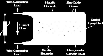
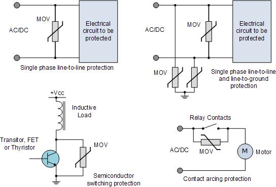
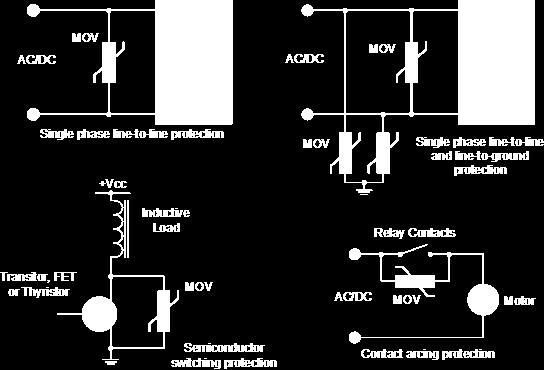
18 Overvoltage protection. Metal Oxide Varistor (MOV) Varistor current-voltage characteristics for zinc oxide (ZnO) and silicon carbide (SiC) devices

19 Metal Oxide Varistor (MOV) Voltage vs Current characteristics of varistors Circuit symbol of varistor

20 MOV Lifetime (number of operating cycles/pulses) is reduced with higher currents Current rating of varistor as a function of impulse duration
21 Avalanche diodes Used for overvoltage protection too Works with both polarities, pnp-structure Used also in balancing voltages in series connections, Chapter 7
22 Breakover diodes, overvoltage protection of thyristors Dk turns on at overvoltage and protects T D needed because of lacking reverse blocking capability of Dk Diode in gate control circuit of thyristor Current vs. voltage characteristics of breakover diode, similar to thyristor
23 Fast fuses for semiconductors Fuse element W = R 0 R = constant t si(t) 2 dt = constant 0 t si(t) 2 dt = I 2 t s = constant I 2 t s is fuse specific value Seating plate Sand (inside the body) Body
24 Operating principle of a fuse Prospective short-circuit current Fuse current Supply voltage t s = Pre-arcing time t v = Arcing time

25 Fuse pre-arcing time curve Pre-arcing time as function of prospective current normally given in data sheets Scaling K is used for other voltage values
26 Fuse dimensioning (Overload) If load changes a lot, some cheking needs to be done, can be classified e.g. according to LK-NES Overloads (1 60 s) Once a month I max < 0,8 * I ts 1 or 2 times per week, I max < 0,7 * I ts Hourly, I max < 0,6 * I ts Fast duration overload (< 1 s) Seldom, I max < 0,7 * I ts Often, I max < 0,6 * I ts
27 Fuse dimensioning (Cyclic load) RMS value for the current I eff = k n=1 I 2 n t n k Load cycle t n n=1 Current is higher than RMS I effhot = 2 n I n hot t n hot n t n hot G = Ieffhot + I effcold 2 2 I effhot Current is lower than RMS I effcold = 2 n I n cold t n cold n t n cold
28 G-factor of fuse If load cycle is more than an hour, G can be used as such If load cycle is les than an hour, scaling as shown below Continuous current rating of the fuse needs to fulfiil I b I effhot G Duration of load cycle (min)
29 Fuse in DC-circuit DC has no zero crossings Arc-voltage has to bel large enough to drive current to zero Time-constant of the circuit has an effect on dimensioning, voltage rating changes Overcurrents are problematic, fuse can explode! Resonan LC-circuits problematic too, fuse dosen t necessarily work in the first zero crossing Voltage rating as a function of time constant of shortcircuit
30 Fuses in 6-pulse bridge rectifier circuit Three or six fuses Protection against load in rigth figure
31 Fast circuit breakers Operation time < 10 ms Expensive Maintenance costs are cheaper compared to fast fuses, no need to change the fuse, lost operation time minimal
32 PTC Resistor PTC = Positive Temperature Coefficient Resistance 2500 x nominal 120 C => Fault current limited Needs time to cool and recover
Lecture 2. Power semiconductor devices (Power switches)
") Lecture 2. Power semiconductor devices (Power switches) Power semiconductor switches are the work-horses of power electronics (PE). There are several power semiconductors devices currently involved in
Lecture 2. Power semiconductor devices (Power switches) Power semiconductor switches are the work-horses of power electronics (PE). There are several power semiconductors devices currently involved in
ELEC-E8421 Components of Power Electronics. Thyristors
 ELEC-E8421 Components of Power Electronics Thyristors Thyristors Turn on and the di/dt rating At turn on the gate current goes to cathode only at the small region near the gate. The initial turn on area
Second Edition. Power Electronics. Devices and Circuits. V. Jagannathan
 Second Edition Power Electronics Devices and Circuits V. Jagannathan Power Electronics Devices and Circuits SECOND EDITION V. Jagannathan Professor and Head Department of Electrical and Electronics Engineering
FUSES FOR SEMICONDUCTORS
 FUSES FOR SEMICONDUCTORS. POWER SEMICONDUCTORS.. Three families of power semiconductors.. Power semiconductors history.3. Current conversion: one application of the power semiconductors.4. Power semiconductors
Power Semiconductor Switches
 Power Semiconductor Switches Pekik Argo Dahono Power Semiconductor Switches Diodes (Uncontrolled switches) Thyristors (Controllable at turn-on but uncontrolled at turn-off or commonly called as latched
Introduction to Power Electronics - A Tutorial. Burak Ozpineci Power Electronics and Electrical Power Systems Research Center
 Introduction to Power Electronics - A Tutorial Burak Ozpineci Power Electronics and Electrical Power Systems Research Center Agenda 1. The definition of power electronics 2. Power semiconductors 3. Power
8. Filter / Autoranging Rectifier Module (FARM )
") Maxi, Mini, Micro Family DC-DC s and Configurable Power Supplies The Filter / Autoranging Rectifier Module (FARM provides an effective solution for the AC front end of a power supply built with converters.
Maxi, Mini, Micro Family DC-DC s and Configurable Power Supplies The Filter / Autoranging Rectifier Module (FARM provides an effective solution for the AC front end of a power supply built with converters.
1. Troubleshooting 4-2 MT5F Fuji Electric Co., Ltd. All rights reserved.
 Chapter 4 Troubleshooting 1. Troubleshooting 4-2 MT5F33743 Fuji Electric Co., Ltd. All rights reserved. 4-1 This chapter describes how to deal with troubles that may occur while the automotive IGBT module
Fig 1. Circuit Breakers
 Protective Devices for Electrical Control Equipment Fuses, Circuit breakers, Chop off Circuits, Crowbars, Thermostats Arthur Holland, Holland Technical Skills In previous columns I have dealt with protection
Ultra-Rapid Fuse Links for the Protection of Semiconductor Rectifiers
 Ultra-Rapid Fuse Links for the Protection of Semiconductor Rectifiers 1.General The design of rectifier equipment requires specific provisions in the switchgear for the protection of power semiconductor
High Speed Fuse Applications Module 5
 High Speed Fuse Applications Module 5 Power Semiconductors GTO SSR Semiconductors: High speed electronic switches used to manipulate electrical power Diode Thyristor IGBT Module 5 - page 2 2 Application
Electric cars: Technology
 In his lecture, Professor Pavol Bauer explains all about how power is converted between the various power sources and power consumers in an electric vehicle. This is done using power electronic converters.
ELECTRICAL POWER and POWER ELECTRONICS
 Introduction to ELECTRICAL POWER and POWER ELECTRONICS MUKUND R PATEL (cj* CRC Press Taylor & Francis Group Boca Raton London New York CRC Press is an imprint of the Taylor & Francis Croup, an informa
Leadership in fusible circuit protection
 Bussmann series High speed fuse application guide Leadership in fusible circuit protection SERIES Eaton is the leading source of fusible circuit protection solutions in the global marketplace. Eaton s
Ceramic PTC Thermistor:
 Motor Starter In starter circuit for single-phase a.c. motor, CPTC thermistor is in series connection with starting winding of motor. When motor starts, initial resistance of CPTC thermistor is low and
Fuseology. High Speed Fuses
 Fuseology High Speed Fuses The protection needs for solid-state power equipment often differ from electrical equipment; hence, the high speed fuse evolved. The protection of power diodes and SCRs requires
SINAMICS SM150. Siemens product performance features. Competitor product profile. Components. Power, transport units. Service friendliness
 SINAMICS SM150 B.Rasch A&D LD IB mail to: bjoern.rasch@siemens.com Slides: 1 SINAMICS SM150 Product overview Voltage: Power: Motor: Operation: Output frequency: Topology: Technology: Cooling: Closed-loop
Maintenance Manual 13 AMPERE POWER SUPPLY 19A704647P1-P3. Mobile Communications LBI-31801C
 C Mobile Communications 13 AMPERE POWER SUPPLY 19A704647P1-P3 CAUTION THESE SERVICING INSTRUCTIONS ARE FOR USE BY QUALI- FIED PERSONNEL ONLY. TO AVOID ELECTRIC SHOCK DO NOT PERFORM ANY SERVICING OTHER
Application Guide Semiconductor Fuse Links
 Application Guide Semiconductor Fuse Links Power Semiconductor Fuse Applications Guide Contents Pages Introduction... 4 Continuous current rating In... 5 Protection against overcurrents - basic concepts...
Lecture Notes. Snubber Circuits. William P. Robbins Dept. of Electrical and Computer Engineering University of Minnesota. Outline
 Lecture Notes Snubber Circuits William P. Robbins Dept. of Electrical and Computer Engineering University of Minnesota Outline A. Overview of Snubber Circuits B. Diode Snubbers C. Turnoff Snubbers D. Overvoltage
SINAMICS DCM. DC Converter. Application SINAMICS DCM as field supply unit. Edition 04-6/2013. SINAMICS drives
 SINAMICS DCM DC Converter Application SINAMICS DCM as field supply unit Edition 04-6/2013 SINAMICS drives SINAMICS DCM Compact User Manual Legal information Warning notice system This manual contains notices
Fuses Introductory Information
 Fuses Introductory Information Why a Fuse? There are many possible cases for overcurrents to occur due to a malfunction in appliances, including short-circuits: In low output power applications, miniature
High Power Semiconductor Devices and Solid State Switches for Pulsed Discharge Applications
 High Power Semiconductor Devices and Solid State Switches for Pulsed Discharge Applications A. Welleman, W. Fleischmann ABB Switzerland Ltd, Semiconductors, Fabrikstrasse 3, CH-5600 Lenzburg / Switzerland
Application Guide Effective June Protecting semiconductors with high speed fuses
 pplication Guide 10507 Effective June 2016 Protecting semiconductors with high speed fuses Contents : Introduction 3 bout this guide 3 Background 3 Typical fuse construction 3 Fuse operation 4 Power semiconductors
Presented to the IAPMO Standards Review Committee on December 9, 2013
 Summary of Substantive Changes between the 2010 edition including Updates No. 1 and No. 2 dated September 2010 and August 2011 and the 2013 edition of CSA C22.2 No. 14 Industrial control equipment Presented
MGL Avionics AvioGuard. Fault protected, wide input range, isolated, DC to DC converter for avionics applications
 MGL Avionics AvioGuard Fault protected, wide input range, isolated, DC to DC converter for avionics applications General The MGL Avionics AvioGuard is a fault protected DC to DC converter. It is able to
POWR-SPEED FUSES TECHNICAL APPLICATIONS GUIDE
 POWR-SPEED FUSES TECHNICAL APPLICATIONS GUIDE TABLE OF CONTENTS 1.0 INTRODUCTION... 3 2.0 POWER SEMICONDUCTOR DEVICES... 4 2.1 Power Semiconductor Device Classification... 4 3.0 OVERCURRENT PROTECTION
Reference Guide to Standard Products Part No. Applicable Standards Varistor at ma Allowable Clamping at 8/20μs Peak Current at 8/20μs(A) Recommended A
 Recommended A") ZNR Transient/Surge Absorbers Type: D Series: E ZNR Transient/Surge Absorber, Series E, Type D features large surge current and energy handling capability for absorbing transient overvoltage in a compact
ZNR Transient/Surge Absorbers Type: D Series: E ZNR Transient/Surge Absorber, Series E, Type D features large surge current and energy handling capability for absorbing transient overvoltage in a compact
Zero-turn-off thyristor zero voltage block media recovery analysis of influencing factors FANG Wei1, a*, XU Guo-shun1, b, ZHUANG Jin-wu1, c
 International Symposium on Mechanical Engineering and Material Science (ISMEMS 2016) Zero-turn-off thyristor zero voltage block media recovery analysis of influencing factors FANG Wei1, a*, XU Guo-shun1,
Low Voltage Fuses General information
 General information Description FUJI low voltage current-limiting fuses are designed to give protection to power supply and distribution circuits and equipment such as motor starter and semiconductors.
High Speed Fuses. Section Contents Page
 Section Contents Page General pplications.......................1-13 North merican fuses & accessories...........1-11 DFJ - High speed Class J fuse.................. 15 Square ody fuses & accessories............
Electrical Test of STATCOM Valves
 21, rue d Artois, F-75008 PARIS 619 CIGRE 2016 http : //www.cigre.org Electrical Test of STATCOM Valves Baoliang SHENG 1, Christer DANIELSSON 1, Rolf NEUBERT 2, Juha TURUNEN 3, Yuanliang LAN 4, Fan XU
Tadiran Lithium Battery Packs for Long Term Ocean Deployments
 Tadiran Lithium Battery Packs for Long Term Ocean Deployments Lee Gordon Doppler Ltd. 858-486-4077 lee@dopplerltd.com Alkaline Pack for a Doppler Profiler Long Term Ocean Deployments Duration: weeks to
Three phase controlled rectifier SZ5 unit
 Sheet 1 PRODUCT DESCRIPTION The three phase controlled is a power device for convert the three phase ac input voltage in a continuous rectifier output voltage with a three phase bridge thyristor rectifier.
Chapter 5. Protection Circuit Design
 Chapter 5 Protection Circuit Design CONTENTS Page 1 Short circuit (overcurrent) protection 5- Overvoltage protection 5-6 This section explains the protection circuit design. 5-1 1 Short circuit (overcurrent)
Product Line Card 2018
 Product Line Card 2018 Our Manufacturers Tel: 01444 243 452 The Custom Power Specialist www.gdrectifiers.co.uk Email: enquiries@gdrectifiers.co.uk About Us GD Rectifiers is a Global Manufacturer and Distributor
2.0 CONSTRUCTION 3.0 OPERATION. SA-1 Generator Differential Relay - Class 1E 2.5 TRIP CIRCUIT
 41-348.11C SA-1 Generator Differential Relay - Class 1E 2.0 CONSTRUCTION The type SA-1 relay consists of: Restraint Circuit Sensing Circuit Trip Circuit Surge Protection Circuit Operating Circuit Amplifier
1SVC F SVC F 0607 R100.20/30 R100.45
 SIGMASWITCH Content Solid state relays Description, certificates, approvals... 163 Ordering details... 164 Technical data R111, R12x... 167 Technical data R100... 168 Technical data HDS R2... 169 Selection
ECET 211 Electric Machines & Controls Lecture 6 Contactors and Motor Starters. Lecture 6 Contactors and Motor Starters
 ECET 211 Electric Machines & Controls Lecture 6 Contactors and Motor Starters Text Book: Chapter 6, Electric Motors and Control Systems, by Frank D. Petruzella, published by McGraw Hill, 2015. Paul I-Hai
EE 741 Over-voltage and Overcurrent. Spring 2014
 EE 741 Over-voltage and Overcurrent Protection Spring 2014 Causes of Over-voltages Lightning Capacitor switching Faults (where interruption occurs prior to zero current crossing) Accidental contact with
Switching & Protecting Electronics in Battery-Powered Systems
 Switching & Protecting Electronics in Battery-Powered Systems By Pinkesh Sachdev Product Marketing Engineer, Mixed Signal Products Linear Technology Corp. Introduction Battery-powered electronics poses
Contents. Prefece. List of Acronyms «xxi. Chapter 1 History of Power Systems 1
 Contents Prefece xv Author xix List of Acronyms «xxi Chapter 1 History of Power Systems 1 LI Thomas A. Edison (1847-1931) 5 1.2 Nikola Tesla (1856-1943) 7 1.3 Battle of AC versus DC 8 1.4 Today's Power
Suppression Products. Overvoltage Suppression Products: Introduction Industrial Varistor Products 173
 : Introduction 171-172 Industrial aristor Products 173 Surge Fuses 174 www.littelfuse.com 2005 Littelfuse POWR-GAR Products Catalog Courtesy of Steven ngineering, Inc.-230 Ryan Way, South San Francisco,
TSTE25 Power Electronics. Lecture 4 Tomas Jonsson ISY/EKS
 TSTE25 Power Electronics Lecture 4 Tomas Jonsson ISY/EKS 2016-11-09 2 Outline The thyristor Controlled rectifier and inverters Single phase Three phase 2016-11-09 3 Thyristors Only possible to turn on
Plug-in relays Mini ISO relays
 Powertrain Systems Chassis Systems Safety Security Body Driver Information Convenience Description Features Limiting continuous current 70 A Dimensional characteristics and the functional allocation of
Metal Oxide Varistor (MOV) Data Sheet
 Data Sheet") Metal Oxide Varistor (MOV) Data Sheet Features Wide operating voltage (V 1mA ) range from 18V to 1800V Fast responding to transient over-voltage Large absorbing transient energy capability Low clamping
Metal Oxide Varistor (MOV) Data Sheet Features Wide operating voltage (V 1mA ) range from 18V to 1800V Fast responding to transient over-voltage Large absorbing transient energy capability Low clamping
SECTION 4 ELECTRIC MOTORS UNIT 17: TYPES OF ELECTRIC MOTORS UNIT OBJECTIVES UNIT OBJECTIVES 3/21/2012
 SECTION 4 ELECTRIC MOTORS UNIT 17: TYPES OF ELECTRIC MOTORS UNIT OBJECTIVES After studying this unit, the reader should be able to Describe the different types of open single-phase motors used to drive
SIMOREG DC Master. Application SIMOREG as a field supply unit. 6RA70 Series
 s SIMOREG DC Master 6RA70 Series Application SIMOREG as a field supply unit Microprocessor-Based Converters from 6kW to 2500kW for Variable-Speed DC Drives Edition 03 Edition 03 04.05 NOTE This application
Ultra Rapid Fuses. For Semiconductor Protection
 UR Ultra Rapid Fuses For Semiconductor Protection Over many decades SIBA has developed a very comprehensive product line of Ultra Rapid fuses that has achieved worldwide acceptance. SIBA's worldwide distribution
Voltage limiting device HVL
 Datasheet Voltage limiting device HVL 120-0.3 1 2 3 3 Equivalent circuit of voltage limiting device Type HVL 120-0.3 1 MO-surge arrester 2 Trigger electronics 3 Thyristor Product Description The HVL 120-0.3
3. OPERATION 2.1. RESTRAINT CIRCUIT 2.6. INDICATING CIRCUIT 2.2. OPERATING CIRCUIT 2.7. SURGE PROTECTION CIRCUIT 2.3.
 41-348.1H Type SA-1 2.1. RESTRAINT CIRCUIT The restraint circuit of each phase consists of a center-tapped transformer, a resistor, and a full wave rectifier bridge. The outputs of all the rectifiers are
Pan Overseas Zinc Oxide Varistors
 PVR - ZINC OXIDE VARISTORS Introduction Zinc Oxide Varistor is a non-linear resistance device, whose voltage and current relationship vary according to the Law of Powers. When high transients or surges
Insulation method Zero-cross function Indicators Applicable output load Model number Phototriac coupler Yes Yes (See page 6) Main Circuit
 Main Circuit") SSR with Failure Detection Function Detects failures in SSRs used for heater temperature control and simultaneously outputs alarm signals. This product supports the safe design of heater control systems,
SSR with Failure Detection Function Detects failures in SSRs used for heater temperature control and simultaneously outputs alarm signals. This product supports the safe design of heater control systems,
Course Name: POWER ELECTRONICS Course Code: EE603 Credit: 4
 Course Name: POWER ELECTRONICS Course Code: EE603 Credit: 4 Prerequisites: Sl. No. Subject Description Level of Study 01 Basic Electronics p n junction, Diode, BJT, MOSFET 1 st Sem, 2 nd Sem 02 Circuit
Silvertel. Ag Features. Multi-Stage Charging. Battery Reversal Protection. Reduced Power Consumption. Wide DC or AC Input Voltage Range
 Silvertel V1.1 October 2012 Pb 1 Features Multi-Stage Charging Battery Reversal Protection Reduced Power Consumption Wide DC or AC Input Voltage Range High Efficiency DC-DC Converter Programmable Charge
Company profile 2 Profile of ČKD ELEKTROTECHNIKA 2
 Applications Table of contents Company profile 2 Profile of ČKD ELEKTROTECHNIKA 2 Applications 3 Power semiconductor units PSU 3 Custom-design PSU 4 PSU wirings 5 GU 3391 control unit for tyristors 6
Power Conversion Systems 2005/2006. Schaefer the Power to make it happen.
 Power Conversion Systems 2005/2006 Schaefer the Power to make it happen. Company profile workforce experience customer orientation flexibility reliability Schaefer Elektronik, founded in 1969, has grown
Application Note CTAN #127
 Application Note CTAN #127 Guidelines and Considerations for Common Bus Connection of AC Drives An important advantage of AC drives with a fixed DC is the ability to connect the es together so that energy
Description. Features. Applications. Environmental. Characteristics Symbol Conditions Value Unit Repetitive Peak Reverse Voltage V RRM.
 LSICSD1A5 RoHS Pb Description This series of silicon carbide (SiC) Schottky diodes has negligible reverse recovery current, high surge capability, and a maximum operating junction temperature of 175 C.
Rich, unique history of engineering, manufacturing and distributing
 Rich, unique history of engineering, manufacturing and distributing United Silicon Carbide, inc. is a semiconductor company specializing in the development of high efficiency Silicon Carbide (SiC) devices
Voltage limiting device HVL
 Datasheet Voltage limiting device HVL 60-0.3 1 2 3 3 Equivalent circuit of voltage limiting device Type HVL 60-0.3 1 MO-surge arrester 2 Trigger electronics 3 Thyristor Product Description The HVL 60-0.3
Development and Operational Advantages of a Solid State Circuit Breaker with Current Limiting
 Development and Operational Advantages of a Solid State Circuit Breaker with Current Limiting Breaker Technology Operational Advantages Development Schedule Dave Richardson, Ph.D.,P.E. Powell Power Electronic
TOTALFLOW Technical Bulletin 82
 TOTALFLOW Technical Bulletin 82 PTC Fuses Being Added To Totalflow Electronic Circuit Boards Totalflow Technical Bulletin Version 1.0, Revision AA (12 June 2000) ABB Automation Inc. Automation ABB Automation
AC/DC FFE converter power module
 Sheet 1 PRODUCT DESCRIPTION The converter series FFE (Fundamental Front End) consists of a three-phase IGBT bridge working at mains frequency and works as rectifier/regenerative bridge allowing the flow
Question Number: 1. (a)
") Session: Summer 2008 Page: 1of 8 Question Number: 1 (a) A single winding machine cannot generate starting torque. During starting the switch connects the starting winding via the capacitor. The capacitor
Session: Summer 2008 Page: 1of 8 Question Number: 1 (a) A single winding machine cannot generate starting torque. During starting the switch connects the starting winding via the capacitor. The capacitor
DRB-1 Series Instruction Manual
 Instruction Manual BEFORE USING THE POWER SUPPLY UNIT Pay attention to all warnings and cautions before using the unit. Incorrect usage could lead to an electrical shock, damage to the unit or a fire hazard.
LSIC2SD065A20A 650 V, 20 A SiC Schottky Barrier Diode
 LSIC2SD065A20A 650 V, 20 A SiC Schottky Barrier Diode RoHS Pb Description This series of silicon carbide (SiC) Schottky diodes has negligible reverse recovery current, high surge capability, and a maximum
LSIC2SD065C06A 650 V, 6 A SiC Schottky Barrier Diode
 LSICSD065C06A 650 V, 6 A SiC Schottky Barrier Diode Description This series of silicon carbide (SiC) Schottky diodes has negligible reverse recovery current, high surge capability, and a maximum operating
Solid-State Relays. Solid-State Relays. Features. Description. Overview
 Features Rugged, epoxy encapsulation construction 4,000 volts of optical isolation Subjected to full load test and six times the rated current surge before and after encapsulation Unique heat-spreader
CAPACITORS FOR POWER ELECTRONICS
 CAPACITORS FOR POWER ELECTRONICS Positive Development in Power Electronics INDEX Page No: 0. CONTENTS 1 1. INTRODUCTION 2 2. APPLICATION 2 3. DEFINITIONS 3 4. CAPACITOR CONSTRUCTION 5 5. CAPACITOR SAFETY
Newly Developed High Power 2-in-1 IGBT Module
 Newly Developed High Power 2-in-1 IGBT Module Takuya Yamamoto Shinichi Yoshiwatari ABSTRACT Aiming for applications to new energy sectors, such as wind power and solar power generation, which are continuing
Low and High Voltage Power Supplies
 Low and High Voltage Power Supplies We work according to ISO 9001: 2008 Since 1994 Fug works according to the quality assurance system ISO 9001. All shipped units are checked and documented in our testing
The Z Series. SCR Power controllers for resistance heating applications. Zero-Fired SCR Power Controllers AMPS VAC
 The Z Series Zero-Fired SCR Power Controllers 60-1200 AMPS 120-600 VAC SCR Power controllers for resistance heating applications. ROBICON 1996 Rev. 7/96 Applications Robicon s Z series power controls are
Shunt Capacitor Bank Protection in UHV Pilot Project. Qing Tian
 Shunt Capacitor Bank Protection in UHV Pilot Project Qing Tian 2012-5 INTRODUCTION State Grid Corp. of China, the largest electric power provider in the country, has first build a 1000 kv transmission
Thyristors Characteristics
 Electrical Engineering Division Page 1 of 15 A thyristor is the most important type of power semiconductor devices. They are extensively used in power electronic circuits. They are operated as bi-stable
FUSE TECHNOLOGY Ambient temperature
 This fuse technology guide will discuss basic fuse operating, application, and selection criteria concepts. The intended purpose of this section is to aid designers with the operation and characteristics
Design and Reliability of a High Voltage, high Current Solid State Switch for Magnetic Forming Applications
 Design and Reliability of a High Voltage, high Current Solid State Switch for Magnetic Forming Applications A. WELLEMAN, R. LEUTWYLER, S. GEKENIDIS ABB Switzerland Ltd, Semiconductors, Fabrikstrasse 3,
PTC Thermistors. Application notes. Date: January 2016
 PTC Thermistors Application notes Date: January 2016 EPCOS AG 2016. Reproduction, publication and dissemination of this publication, enclosures hereto and the information contained therein without EPCOS'
PHASETRONICS SCR Power Control Specialists
 PHASETRONICS SCR Power Control Specialists EP1 Series - Power Control Single Phase SCR 85 to 1000 Amps OPERATION & SERVICE MANUAL Phasetronics, Inc. P.O. Box 17159 13214-38th Street North Clearwater, FL
NEW CURRENT- LIMITING AND INTERRUPTING DEVICE CONTRA CURRENT- LIMITING FUSES
 NEW CURRENT- LIMITING AND INTERRUPTING DEVICE CONTRA CURRENT- LIMITING FUSES J. Czucha, T. Lipski J. yborski Technical University of Gdansk Gdansk - Poland Abstract: Advent of new era in the overcurrent
Characteristics of LV circuit breakers Releases, tripping curves, and limitation
 Characteristics of LV circuit breakers Releases, tripping curves, and limitation Make, Withstand & Break Currents A circuit breaker is both a circuit-breaking device that can make, withstand and break
Description. Features. Applications. Environmental. Characteristics Symbol Conditions Value Unit Repetitive Peak Reverse Voltage V RRM.
 LSIC2SD12C1, 12 V, 1 A, TO-252-2L (DPAK) LSIC2SD12C1 RoHS Pb Description This series of silicon carbide (SiC) Schottky diodes has negligible reverse recovery current, high surge capability, and a maximum
Induction Power Supply Technical/Service manual for 12.5kW-40kW/480V input 2012
 Induction Power Supply Technical/Service manual for 12.5kW-40kW/480V input 2012 1 INDEX I) SETUP AND USE.. 3 A) Features...3 B) Front panel description...3 C) Set-up...4 D) Tips for Dependable Operation.5-6
CHAPTER 3 TRANSIENT STABILITY ENHANCEMENT IN A REAL TIME SYSTEM USING STATCOM
 61 CHAPTER 3 TRANSIENT STABILITY ENHANCEMENT IN A REAL TIME SYSTEM USING STATCOM 3.1 INTRODUCTION The modeling of the real time system with STATCOM using MiPower simulation software is presented in this
CHAPTER 5 FAULT AND HARMONIC ANALYSIS USING PV ARRAY BASED STATCOM
 106 CHAPTER 5 FAULT AND HARMONIC ANALYSIS USING PV ARRAY BASED STATCOM 5.1 INTRODUCTION Inherent characteristics of renewable energy resources cause technical issues not encountered with conventional thermal,
LSIC2SD065E40CCA 650 V, 40 A SiC Schottky Barrier Diode
 LSIC2SD065E40CCA 650 V, 40 A SiC Schottky Barrier Diode RoHS Pb Description This series of silicon carbide (SiC) Schottky diodes has negligible reverse recovery current, high surge capability, and a maximum
Thyristor Power Controllers for Resistive and Inductive loads (Product Code 21.3)
") Thyristor Power Controllers for Resistive and Inductive loads (Product Code 21.3) 1 Model Wise Descriptions: Sr. No Model Product Description 21.3.1 POW-1 Single Phase SCR Power Controller for single phase
Thyristor Power Controllers for Resistive and Inductive loads (Product Code 21.3) 1 Model Wise Descriptions: Sr. No Model Product Description 21.3.1 POW-1 Single Phase SCR Power Controller for single phase
Protective firing in LCC HVDC: Purposes and present principles. Settings and behaviour. V. F. LESCALE* P. KARLSSON
 21, rue d Artois, F-75008 PARIS B4-70 CIGRE 2016 http : //www.cigre.org Protective firing in LCC HVDC: Purposes and present principles. Settings and behaviour. V. F. LESCALE* P. KARLSSON VILES Consulting
Power Supply Technical Information
 Supply Technical Information supplies Supply Overview What is a Supply? Commercial AC power distributed from power plants cannot be supplied directly to the ICs and other electronic components built into
DPX30-xxSxx DC-DC Converter Module 9.5 ~ 18 VDC and 18 ~ 36 VDC and 36~ 75 VDC input; 3.3 to 28 VDC Single Output; 30 Watts Output Power
 DC-DC Converter Module 9.5 ~ 18 VDC and 18 ~ 36 VDC and 36~ 75 VDC input; 3.3 to 28 VDC Single Output; 30 Watts Output Power FEATURES NO MINIMUM LOAD REQUIRED 1600VDC INPUT TO OUTPUT ISOLATION SCREW TERMINALS
DPX30-xxDxx DC-DC Converter Module 9.5 ~ 18 VDC and 18 ~ 36 VDC and 36~ 75 VDC input; ±12 to ±15 VDC Dual Output; 30 Watts Output Power
 DC-DC Converter Module 9.5 ~ 18 VDC and 18 ~ 36 VDC and 36~ 75 VDC input; ±12 to ±15 VDC Dual Output; 30 Watts Output Power FEATURES NO MINIMUM LOAD REQUIRED 1600VDC INPUT TO OUTPUT ISOLATION SCREW TERMINALS
Temperature Controllers
 Controllers SCR Power Controllers Introduction to Silicon Controlled Rectifier (SCR) Power Controllers Features and Benefits of SCRs High reliability Because the SCR power controller is a solid-state device,
Description. Features. Applications. Environmental. Characteristics Symbol Conditions Value Unit Repetitive Peak Reverse Voltage V RRM.
 LSICSD1A5, 1 V, 5 A, TO--L LSICSD1A5 RoHS Pb Description This series of silicon carbide (SiC) Schottky diodes has negligible reverse recovery current, high surge capability, and a maximum operating junction
DPX30-xxWDxx DC-DC Converter Module 10 ~ 40VDC, 18 ~ 75VDC input; ±12 to ±15 VDC Dual Output; 30 Watts Output Power
 DC-DC Converter Module 10 ~ 40VDC, 18 ~ 75VDC input; ±12 to ±15 VDC Dual Output; 30 Watts Output Power FEATURES NO MINIMUM LOAD REQUIRED 1600VDC INPUT TO OUTPUT ISOLATION SCREW TERMINALS FOR INPUT AND
RSS Series Panel Mount Solid State Relays. 4,000 RMS (minute)
") RSS Series Panel Mount Solid State Relays Key features of the RSS series include: Photo isolation 1,200 volt blocking voltage 4,000 volt optical isolation Zero voltage turn-on 100% tested at rated current
RSS Series Panel Mount Solid State Relays Key features of the RSS series include: Photo isolation 1,200 volt blocking voltage 4,000 volt optical isolation Zero voltage turn-on 100% tested at rated current
GEN2 SiC Schottky Diode. Description. SiC Schottky Diode. Features. Applications. Environmental
 GEN2 LSIC2SD12A8, LSIC2SD12C8, 12 V, 8 A, A, TO-252-2L TO-22-2L(DPAK) LSIC2SD12C8 RoHS Pb Description This series of silicon carbide (SiC) Schottky diodes has negligible reverse recovery current, high
Temperature Controllers
 SCR Power Controllers Introduction to Silicon Controlled Rectifier (SCR) Power Controllers Features and Benefits of SCRs High reliability Because the SCR power controller is a solid-state device, it provides
Basic Characteristics Data
 Basic Characteristics Data Basic Characteristics Data Model Circuit method Switching frequency [khz] (reference) current [] Inrush current protection Material PCB/Pattern Single sided Double sided Series/Parallel
Features. Description. Table of Contents
 Features Very low profile Very high efficiency (typically 90%) Single and dual output versions Input voltages from 24V to 110VDC nominal voltages from 5V to 48VDC -40 C to +71 C operation without de-rating
GEN2 SiC Schottky Diode LSIC2SD120E40CC, 1200 V, 40 A, TO-247-3L. Description. SiC Schottky Diode. Features. Applications.
 LSIC2SD12E4CC RoHS Pb Description This series of silicon carbide (SiC) Schottky diodes has negligible reverse recovery current, high surge capability, and a maximum operating junction temperature of 175