VEHICLE STARTING & CHARGING SYSTEMS
|
|
|
- Sara Dean
- 6 years ago
- Views:
Transcription


1 100% New Units VEHICLE STARTING & CHARGING SYSTEMS & 3

2 TABLE OF CONTENTS Warranty Alternators and Starters...3 Alternators Features and Benefits...4 Installation...5 Model 21/ Model Model Model Model Model Leece Neville Load Handler Starters Features and Benefits...19 Installation Model Model Model R
3 Warranty Terms and Conditions Precision Rebuilders warrants each Precision Rebuilders product to be free of defects in material or workmanship under normal use and service. The length of the Warranty Period is for a period of one year. The warranty periods commences on the in-service or install date and is not transferable. Failure to provide the in-service or install date on the warranty claim tag will cause the warranty period to begin on the date the part was manufactured. A completed warranty claim form should accompany all parts submitted to Precision Rebuilders for warranty consideration. The claim form should contain all of the information required. Lack of proper information may result in denial of warranty claim. Claims must be submitted no later than 60 days after part is removed. This warranty does not apply if in sole judgment of Precision Rebuilders, the product has been consumed, subject to accident, faulty repair, improper adjustment, installation, lubrication, or wiring, neglect, misuse; or is caused by failure of a part not supplied by Precision Rebuilders. This warranty shall not apply if any Precision Rebuilders product is used for a purpose for which it is not designed or altered in any way so as to affect adversely its performance and reliability. Precision Rebuilders requires the examination of ALL products or parts to confirm that the part has failed as a result of material or workmanship. Transportation for products and parts submitted to Precision Rebuilders for warranty consideration must be prepaid. Repaired or replaced Precision Rebuilders parts will be returned, transportation and handling charges collect. No charge will be made for labor or material in effecting such repairs. The obligation of Precision Rebuilders under this Warranty is limited to making good by replacement of the defect part. This Warranty does not apply to products or parts where adjustments will correct the alleged defect Precision Rebuilders neither assumes nor authorizes any other person to assume on its behalf any other warranty or liabilities in connection with Precision Rebuilders products. Precision Rebuilder s WARRANTY IS EXCLUSIVE AND IN LIEU OF ALL OTHER WARRANTIES, EXPRESSED, IMPLIED, OR STATUATORY INCLUDING BUT NOT LIMITED TO ANY WARRANTY OF MERCHANTABILITY OR FITNESS FOR PARTICULAR PURPOSES. THIS WARRANTY DOES NOT APPLY TO LOSS OF VEHICLE OR EQUIPMENT, LOSS OF TIME, INCONVENIENCE, OR OTHER INCIDENTAL OR CONSEQUENTIAL DAMAGES. Precision Rebuilders SHALL NOT BE LIABLE FOR INCIDENTAL OR CONSEQUENTIAL DAMAGES arising out of or from the use of Precision Rebuilders s products by the buyer, its assignees, employees, agents or customers. Alternators & Starters Limited Warranty All products have a one year warranty (calculated from the date of sale) for failure to perform due to defects in material or workmanship. Before warranty is determined the Distributor must return the alleged warranty product with the proper documentation to the plant for testing. The product will be tested at the plant and a return call to the Distributor will be made to communicate the Failure Analysis. If the product is warrantable, the customer will be issued a credit for the unit only. If the product tests OK, the unit will be returned to the Distributor. There are no warranties or conditions beyond this document and no person is granted or authorized to express or imply additional warranty or liability. The buyer s sole remedy for a warranted product is replacement of product per conditions above. In no event shall Precision Rebuilders, its agents or employees be responsible for incidental or consequential damages nor negligence in any respect. page i

4 HEAVY DUTY ALTERNATORS 4
5 ALTERNATOR INSTALLATION INSTRUCTIONS WARNING: ALWAYS USE PROPER EYE PROTECTION WHEN PERFORMING ANY MECHANICAL REPAIRS TO A VEHICLE -INCLUDING, BUT NOT LIMITED TO, ANY INSTALLATION AND OR REPAIRS TO THE ALTERNATORS. FAILURE TO USE PROPER EYE PROTECTION CAN LEAD TO SERIOUS AND PERMANENT EYE DAMAGE. Only perform the mechanical functions that you are properly qualified to perform. Mechanical repairs that are beyond your technical capabilities should be handled by a professional installation specialist. WARNING: To avoid injury or damage, always disconnect the negative cable at the battery before removing or replacing the alternator. The alternator output terminal is always live ( hot ). If the battery is not disconnected, a tool accidentally touching this terminal and ground can quickly get hot enough to burn skin or damage the tools and surrounding parts. CAUTION: Remove jewelry before working on electrical system to avoid injury or damage to the system. PULLEY INSTRUCTIONS Use pulley from old alternator if this alternator does not have a pulley or pulley supplied is different from the one on alternator being replaced. NOTICE! When changing the pulley, keep the alternator in the -horizontal position and do not apply any pressure to end of the shaft. Internal damage will occur if the shaft is pushed back and turned. If there were spacers: when the fan and pulley were removed, make sure all spacers are replaced when installing the fan and pulley on this alternator. Hold the shaft by placing a hex wrench in the hexagonal hole in the shaft while removing or installing the pulley. Tighten the pulley nut to Nm (70-80 Ibs ft.). BELT TENSIONING INSTRUCTIONS Improper belt tension can cause premature alternator failure. Use a torque wrench to tighten mounting bolts to specified torque. Follow vehicle or engine manufacturer s specifications carefully for belt tension and mounting bolts torque. DO NOT OVER TIGHTEN BELT! TERMINAL DESCRIPTIONS POS Terminal - Output terminal connects to the Positive (+) Battery terminal. R Terminal - Relay terminal carries half systems voltage and may be used for certain types of control relays, charge indicators, tachometers or similar devices. The current draw should not exceed four (4) amperes. Notice! Do not install the remote sense lead to this terminal. I Terminal - Indicator lamp/ignition terminal carries full system voltage. Current draw should not exceed one (1) ampere. It is recommended current is not drawn from this terminal. Ground Screw - Ground lead ensures alternator is grounded and is strongly recommended for optimum performance. Remote Sense Terminal - Monitors batteries system voltage at the Batteries or a common distribution point. The Sense terminal is the fourth terminal and is identified with a remote sense label on the back cover plate. Notice! Do not connect anything but the remote sense line to this terminal. If installing a remote sense alternator in a vehicle without a remote sense line, connect a lead from the Voltage Sense terminal to the Positive (+) Battery terminal or the common distribution point at the Starter Solenoid Battery (+) terminal. If installing a non-remote sense alternator in a vehicle that has a remote sense line, disconnect and secure the wire from the battery. Notice! Be careful not to ground the leads open end and if it has a fuse it should be deactivated. Only connect the sense line to the remote sense terminal. The R Terminal is Not the Remote Sense Terminal! INSTALLATION INSTRUCTIONS 1. Disconnect the negative (-) cable at the batteries. 2. Identify and tag all leads when removing the old Alternator and install them on the same terminals of the new Alternator. 3. Insure all leads are hooked back up or contained where they can not ground. 4. Torque all fasteners to values labeled on the illustration. 5. This Alternator may have more terminals than the alternator it is replacing had or used. It will function properly by only hooking up the leads that were used on the alternator being replaced. 5


6 21 / 22 MODEL 21/22 Model Detailed Specifications: 8003N Alternator - Delco 21SI Series 70 Amp/24 Volt, 1-Wire System, Neg. Ground Used On: Cummins, Timberjack w/ Cummins 5.9L, 8.3L Diesel Dim: M6 x 1.0 Batt. Term. Universal R-Term. M4 I-Term. Replaces: Delco , , , N Alternator - Delco 22SI Series 70 Amp/24 Volt, 1-Wire System, Neg. Ground Used On: Cummins, Timberjack w/ Cummins 5.9L, 8.3L Diesel Dim: M6 x 1.0 Batt. Term. Universal R-Term. M4 I-Term. Replaces: Delco , , ,


7 21 / 22 MODEL 8362N Alternator - 22 Model 145 Amp/12 Volt, 1-Wire System, Neg. Ground Application: Various Heavy Duty Makes and Models Replaces: Delco , , Dim: 5/16-18 Batt. Term R-Term., I-Term. Note: Bidirectional Fan wo/ pulley 8076N Alternator - 22 Model 150 Amp/12 Volt, 1-Wire System, Neg. Ground Application: Various Heavy Duty Makes and Models Replaces: Delco , Dim: 1/4-28 Batt. Term. Universal R-Term., 5/16 I-Term. Note: Bidirectional Fan wo/ pulley 7

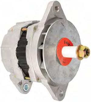
8 24 MODEL 24 Model Design Features and Benefits: Dual Internal Fans create cool environment for bearings and electronics Built-in protection from water and other contaminants with dual spacers and slingers Multi-function regulator with an environmentally sealed packard connector features auto-start and optional remote sense capability Smaller slip rings with higher resistance to brush bounce for extended service life SRE cover protects electronics while managing airflow Easy installation with one-wire connection Advanced design Avalanche press fit diodes provide long life, protection from electrical system spikes 24 Model Detailed Specifications: Performance Output: 160 Amps - 12 Volts Construction: Brush Stator Diameter: 144mm Length (to end of shaft): 223mm Typical Weight: 7.6 kg (16.7 lbs) Speed Capability: Continuous - 10,000 rpm Intermittent 12,000 rpm Temperature Limits: -40 F Ambient (Min) 221 F Ambient (Max) Polarity: Negative Ground Rotation: Clockwise 8


9 24 MODEL 8718N Alternator - 24 Model HP 160 Amp/12 Volt, wo/ pulley Replaces: Delco Dim: 5/16-18 Batt. Term I-Term R-Term. 8719N Alternator - 24 Model HP 160 Amp/12 Volt, wo/ pulley Replaces: Delco Dim: 5/16-18 Batt. Term I-Term R-Term. 9


10 24 MODEL 8704N Alternator - Delco 24SI HP Series 160 Amp/12 Volt Replaces: Cummins ; Delco , , Used On: Mack, Volvo Trucks 8709N Alternator - Delco 24SI HP Series 70 Amp/24 Volt Replaces: Cummins ; Delco , 020, 154;


11 28 MODEL 8741N Alternator - Delco 28SI Series 200 Amp/12 Volt, CW Replaces: Delco , Dim: 5/16-18 Batt. Term R-Term I-Term Remote Sense Term. 8743N Alternator - Delco 28SI Series 200 Amp/12 Volt, CW Replaces: Delco , Dim: 5/16-18 Batt. Term R-Term I-Term Remote Sense Term. 8745N Alternator - Delco 28SI Series 200 Amp/12 Volt, CW Replaces: Delco , Dim: 5/16-18 Batt. Term R-Term I-Term Remote Sense Term. 11
12 35 MODEL 35 Model Detailed Specifications: Performance Output: 105 Amps / 140 Amps - 12 Volts Maximum Speed: 10,000 rpm Continuous 12,000 rpm Intermittent Rotation: Clockwise or Counterclockwise Temperature Limits: -40 F Ambient (Min) +221 F Ambient (Max) Polarity: Negative Ground Standard Mounting: SAE J180 Standard, Quad mount, PAD Mount Weight: 25.4 lbs or 11.5 kg Features and Benefits: Strategically placed radiant vents ensure maximum cooling of internal components in high-temperature underhood environments Premium brushless design extends service life and optimizes performance High-efficiency stator windings and optimized rotor design deliver high output Oversized heavy duty bearings and premium quality steel shaft withstand high vibration and heavy belt loads High thermal-capacity design stands up to extreme temperatures, thermal stress for extended service life All 35 Model Alternators feature Remote Sense Technology capability, optimizing battery state of charge 12


13 35 MODEL 8607N Alternator - 35 Model HP 140 Amp/12 Volt, Neg. Ground Replaces: Delco , , , Dim: 1/4-28 Batt. Term R-Term., I-Term Remote Sense Term. Note: Bidirectional Fan wo/ pulley 8609N Alternator - 35 Model HP 140 Amp/12 Volt, Neg. Ground Replaces: Delco , Dim: 1/4-28 Batt. Term R-Term., I-Term Remote Sense Term. Note: Bidirectional Fan wo/ pulley 8608N Alternator - 35 Model HP 140 Amp/12 Volt, Neg. Ground Replaces: Delco , Dim: 1/4-28 Batt. Term R-Term I-Term Remote Sense Term. Note: Bidirectional Fan wo/ pulley 13


14 36 MODEL 36 Model Detailed Specifications: 8612N Alternator - Delco 36SI Series 170 Amp/12 Volt, Neg. Ground Used On: Freightliner, IHC, Kenworth, Peterbilt, Sterling, Volvo, Western Star Trucks Replaces: Delco , 082, 126, 177; , 046 Dim: 1/4-28 Batt. Term R-Term I-Term Remote Sense Term. 14


15 36 MODEL 8613N Alternator - Delco 36SI Series 170 Amp/12 Volt, Neg. Ground Used On: Kenworth, Peterbilt Trucks Replaces: Delco , Dim: 1/4-28 Batt. Term R-Term I-Term Remote Sense Term. Notes: Bidirectional Fan wo/ pulley. Includes Remote Sense Terminal. 8614N Alternator - Delco 36SI Series 170 Amp/12 Volt, Neg. Ground Used On: Freightliner, IHC, Kenworth, Peterbilt, Sterling, Volvo, Western Star Trucks Replaces: Delco , , Dim: 1/4-28 Batt. Term R-Term I-Term Remote Sense Term. Note: Bidirectional Fan wo/ pulley. Includes Remote Sense Terminal. 15


16 LEECE NEVILLE Detailed Specifications: Temperature Limits: -40 F Ambient (Min) +221 F Ambient (Max) Volts: 12 Amps : 160 Rotation Clockwise Mounting: J-180, Pad Mount Positive Stud Size: 5/16-24 Negative Stud Size: 1/4-28 Rectifier Location: INTEGRAL Shaft Diameter: Pulley: Not Included 8329N Alternator - 8LHA Series / Amp/12 Volt, wo/ Pulley, Dual Foot J-180 Mount Application: Heavy Duty Truck Applications Replaces: Leece-Neville / Motorola 8LHA2070VE, JHO 16


 Engines Replaces: Leece-Neville 2800LC,")
17 LEECE NEVILLE 8410N Alternator - 8LHP Series / 555PM 160 Amp/12 Volt, wo/ Pulley, 4-Point Pad Mount Application: Heavy Duty Truck Applications Replaces: Leece-Neville / Motorola 8LHP2170VE, PHO 7613N-LC Alternator LC Series 160 Amp/12 Volt, Neg. or Pos. Ground, wo/ pulley Application: Ford School Buses, Trucks w/ Cummins 5.9L (FD1060), 8.3L (FD1460) Engines Replaces: Leece-Neville 2800LC, A LC Features: Latest OE design, stator activated regulator 17


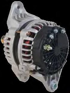
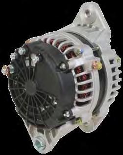
18 LOAD HANDLER 12715N Alternator - Bosch IR/IF 200 Amp/12 Volt, CW Used On: Agco, Case, Caterpillar, Champion, Cummins, Ford Ag & Industrial, John Deere, Massey Ferguson, New Holland, Volvo Trucks Replaces: Bosch , AL9963SB Dim: M8 x 1.25 Batt. Term. (replaces 5/16) M6 x 1.0 Batt. Term. (replaces 1/4) M5 x 0.8 I-Term. Univ. R-Term N Alternator - Bosch IR/IF 200 Amp/12 Volt, CW Used On: Volvo Trucks w/ Cummins ISM, ISX Diesel Engines Replaces: Bosch , AL9962SB; Mercedes Dim: M8 x 1.25 Batt. Term. (replaces 5/16) M6 x 1.0 Batt. Term. (replaces 1/4) M5 x 0.8 I-Term. Univ. R-Term. 18

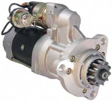
19 HEAVY DUTY STARTERS 19
20 STARTER INSTALLATION INSTRUCTIONS WARNING: ALWAYS USE PROPER EYE PROTECTION WHEN PERFORMING ANY MECHANICAL REPAIRS TO A VEHICLE -INCLUDING, BUT NOT LIMITED TO, ANY INSTALLATION AND OR REPAIRS TO THE STARTER. FAILURE TO USE PROP- ER EYE PROTECTION CAN LEAD TO SERIOUS AND PERMANENT EYE DAMAGE. Only perform the mechanical functions that you are properly qualified to perform. Mechanical repairs that are beyond your technical capabilities should be handled by a professional installation specialist. WARNING: Disconnect the battery cables, starting with the negative cable, and prior to removal of starter to eliminate ELECTRICAL SHOCK HAZARD. CAUTION: Remove jewelry before working on electrical system to avoid injury or damage to the system. BEFORE REPLACING THE STARTER 1. Verify the starter is nonfunctional. The starter can be tested using a carbon pile load tester, a voltmeter and clamp-on style ammeter. 2. Check and follow all safety precautions outlined in the vehicle manufacturer s service manual. 3. Verify the batteries are fully charged and battery terminals are clean and firmly in place. Check battery cable for any corrosion or tears in the insulation. 4. Verify all fuses are good. 5. Check all wiring connections leading to the starter for discoloration, cracks, or evidence or overheating. If any of these symptoms are present, connections must be replaced. Failure to do so may result in starter or vehicle damage. REMOVAL INSTRUCTIONS 1. Disconnect all wire connections and plugs from the starter noting their location and identifying each connector with a piece of tape. This will make installation of the replacement starter easier. 2. Loosen the starter mounting bolts. Note the location of any shims, heat shields, and support brackets. This will also make installation of the replacement starter easier. 3. Remove mounting bolts, tilt or rotate starter to clear flywheel and transmission housing and remove starter from vehicle, noting position of any shims. Shims may be stuck to either the engine mounting or the mounting pads of the starter. 4. Inspect starter drive teeth for damaged pinions. If drive is damaged, it is extremely important that you inspect the flywheel or ring gear for broken or worn teeth. A broken or worn ring gear must be replaced or it will damage the new starter. 20 INSTALLATION INSTRUCTIONS 1. Check and compare the original starter to the replacement starter. All mounting holes wire and plug connectors, and hardware should be compatible. Some vehicle manufacturers may use more than one starter manufacturer. Slight differences in the starter s appearance will not affect the performance of the starter. 2. Install the replacement starter reusing all mounting hardware from the original starter. Refer to vehicle service manual and torque nuts and bolts to the manufacturer s required specifications. 3. Reconnect all electrical connections of the replacement starter to the correct terminals. It is important that all connectors must be clean and fit properly. 4. Reconnect battery cables, connecting positive connections first.
 Drive: Heavy duty design Electrical Soft-Start Engagement System Overcrank Protection: Built-in circuit breaker protects starter from thermal damage and automatically resets at safe")
21 39 MODEL 39 Model Detailed Specifications: Engine Size: Diesel: 12V: up to 15 Liters Rotation: Clockwise Standard Mountings: SAE #1, SAE #3 Standard Pinions: 11-tooth/6-8 pitch Weight: 30.8 lbs (14 kg) Drive: Heavy duty design Electrical Soft-Start Engagement System Overcrank Protection: Built-in circuit breaker protects starter from thermal damage and automatically resets at safe operating temperature Jump Start Protection: Special shield and solenoid cap available to meet SAE J1493 recommendations Maximum Torque gearing system delivers high torque output and starting power in a low mass, lightweight design Sealed noseless configuration reduces debris accumulation and contamination-related maintenance and expense Electrical Soft-Start Engagement System rotates pinion for proper ring-gear engagement before cranking, minimizing tooth abutment-related damage Forged gear support and high strength steel shafts provide superior durability Labyrinth drain housing design utilizes multiple drain points with O-Ring seals for protection from environmental contaminants Heavy duty bearing and bushing system increases motor life and reliability Cast aluminum drive and commutator end housings provide high strength, lightweight construction OCP (Overcrank Protection) protects starter from thermal damage and automatically resets after reaching a safe operating temperature 6910N Starter - Delco 39MT Series 12 Volt, CW, 12-Tooth Pinion Replaces: Delco , , , , , , , Used On: Freightliner, Sterling, Western Star w/ Mercedes MBE-4000 Engines Note: Solenoid positioned at 82 degrees. Features: - IMS (Integral Magnetic Switch) - OCP (Overcrank protection) 21

 - OCP (Overcrank")
22 39 MODEL 6911N Starter - 39 Model 12 Volt, CW, 11-Tooth Pinion, OCP Thermostat Application: Caterpillar C15, Cummins ISX, Detroit Diesel S60, Freightliner, International, Volvo Truck Replaces: Delco , 040, 083, 289; ; , ; , 516, 518, 519, 521 Notes: Solenoid positioned at 82. Features: IMS (Integral Magnetic Switch) OCP (Overcrank protection) 6912N Starter - Delco 39MT Series 12 Volt, CW, 11-Tooth Pinion Replaces: Delco , , , Used On: Kenworth, Peterbilt w/ Caterpillar C9, C10, C11, C12, C15; Cummins ISM, ISX Diesel Engines Features: - IMS (Integral Magnetic Switch) - OCP (Overcrank protection) Note: Solenoid positioned at 82 degrees. 22


23 39 MODEL 6913N Starter - Delco 39MT Series 12 Volt, CW, 12-Tooth Pinion Replaces: Delco , , , Used On: Volvo Trucks D12 Features: - IMS (Integral Magnetic Switch - OCP (Overcrank protection) 6914N Starter - Delco 39MT Series 12 Volt, CW, 11-Tooth Pinion, OCP Thermostat Replaces: Delco , 288; ; , 505, 531; Used On: Mack Trucks E-7 Notes: Solenoid positioned at 52 degrees. 23


24 39 MODEL 6867N Starter - Delco 39MT Series 12 Volt, CW, 11-Tooth Pinion Rotatable nose, OCP & IMS Application: Freightliner, Sterling, Western Star, Kenworth, Peterbilt, Mack and Volvo Replaces: Delco Remy , , , , , , , , , , , N Starter - Delco 39MT Series 12 Volt, CW, 12-Tooth Pinion Rotatable nose, OCP & IMS Application: Navistar Cummins Engines Replaces: Cummins , Delco Remy , , , , , , , , , , , , , , , , , , , , , , , , , Denso , Freightliner MITIN1378, Mitsubishi M009T70279, M9T70279, M9T72078, Volvo , , , , VV0279


25 39 MODEL 6924N Starter - Delco 39MT Series 12 Volt, CW, 11-Tooth Pinion Rotatable nose, OCP & IMS Application: Navistar Cummins Engines Replaces: Cummins , , Delco Remy , , , , , , , , , , , , , , , , , , , , , , , , , , , , , Denso , , , , , , , , FL0579, FL0777, FL0975, M93579, MIB97059, MIB97059FL, MIB970777, MIB970975, Mack Truck 8MJ4298AM, 8MJ5439M, MK0077, MK1075, MK1078, MK2078, Mitsubishi M009T70579, M009T70979, M9T70579, M9T70979, Navistar C91, IN0976, IN1478, PAC- CAR D D , Peterbilt PC0779, PC0979, PC1379, PC1479, PC1579, PC1779, PC1879, Prestolite (Leece-Neville) M125601, MS2-500, MS2-501, MS2-502, MS2-503, MS2-504, MS2-507, MS2-507, MS2-509, MS2-510, MS2-511, MS2-514, Volvo , VV0776, VV0977, VV0979, VV1076, VV1979, VV

26 42 MODEL 42 Model Detailed Specifications: Engine Size: Diesel: up to 14.8 liters up to 900 cu. in. System Voltage: 12 Volts Rotation: Clockwise or Counterclockwise Standard Pinions: 11-tooth/6-8 pitch, Weight: 58 lbs (26.3 kg) Rotatable Drive Housing: Two-piece rotatable drive housing Drive: Heavy duty design Positive engagement Rubber shock absorber Overcrank Protection: (Optional) Prevents overcrank heat damage Circuit breaker automatically resets after it has cooled Jump Start Protection: (Optional) Special shield and solenoid cap available to meet SAE J1493 recommendations 6356N Starter - 42 Model 12 Volt, CW, 12-Tooth Pinion Replaces: Delco & others; Delco Reman Note: Solenoid positioned at N Starter - 42 Model 12 Volt, CW, 12-Tooth Pinion Replaces: Caterpillar 0R5218, 7N6503, 9L3597; Cummins RX, ; Delco , 356, 362, 370, 379, 385, 387, 394, 399, 403, 404, 405, 425, 429, 441, 443, 452, 467, 469, 471, 480, 487, 492, 496; , 775, 783, 795, 806, 820, 935, 937, 938, 939, 942, 943, 961, 983; , 804, 835, 931, 934, 936, 992, 994, , , , , ; Delco Reman ; IHC C91, C92

27 42 MODEL 6513N Starter - 42 Model 12 Volt, CW, 11-Tooth Pinion, w/ OCP Thermostat Replaces: Delco & others; Delco Reman Note: Solenoid positioned at N Starter 42MT Series 24 Volt, CW, 11-Tooth Pinion Replaces: Delco , & others; Delco Reman N Starter - 42 Model 12 Volt, CW, 11-Tooth Pinion, OCP Thermostat Application: Freightliner, IHC, Kenworth, Peterbilt, Sterling, Volvo, Western Star Replaces: Delco , , , , Notes: Solenoid positioned at


28 R5 MODEL 19503N Starter - R5 Series OSGR 5.0KW/12 Volt, CW, 10-Tooth Pinion Replaces: Denso Used On: Freightliner, International, Kenworth, Peterbilt, Sterling, Volvo Truck w/ Cummins N14 Engines; Freightliner, International w/ Cummins ISX Engines 19502N Starter - R5 Series OSGR 5.0KW/12 Volt, CW, 10-Tooth Pinion Replaces: Denso Used On: Freightliner, International, Kenworth, Peterbilt, Sterling, Volvo Truck w/ Cummins M11 Engines; Freightliner, International, Kenworth, Sterling, Volvo Truck w/ Detroit Diesel S60 Engines; Mack E-Tech, E-7 28


29 R5 MODEL 19501N Starter - Denso R5 Series OSGR 5.0kW/12 Volt, CW, 10-Tooth Pinion Used On: Freightliner, International, Kenworth, Peterbilt, Sterling, Volvo Truck w/ Caterpillar C11, C13, C15; Cummin ISM Engines Replaces: Denso
30 NOTES
31 NOTES

32 V.0613
Heavy Duty Starter Motors
 Heavy Duty Starter Motors Contents The Titan is born 3 The Titan Edge In-line Gear Reduced Features - Benefits 5 Causes and Solutions 6 Technical Guidelines 12V 7 Clocking s 12V 8 3 Cross Reference / Applications12V
a division of Prestolite Electric, Inc. Extreme power for extreme conditions Setting the Standard...Again
 a division of Prestolite Electric, Inc. Extreme power...... for extreme conditions Setting the Standard...Again Feature In-line gear reduced design Rotatable nose housing Power, torque and speed Electrical
INVERTER HARNESS INSTALLATION FOR FREIGHTLINER CASCADIA
 FOR FREIGHTLINER CASCADIA Part #: P808 1004FC 08/05/2014 Doc 1.04 INST065 Page 1 Step 1: Unpack the plate assembly and both positive and negative cables. INSTALLATION INSTRUCTIONS Step 2: Insert the negative
CAPACITOR ACTUATED PORTABLE STARTER CAPS USER GUIDE. INST048 Doc 3.01
 CAPACITOR ACTUATED PORTABLE STARTER CAPS USER GUIDE INST048 Doc 3.01 CONTENTS General Information...2 Charts...3 Before First Use...4 Safety Requirements...5 What to Expect from the CAPS...5 CAPS Diagram...6
SOLAR DASH CHARGING SYSTEM USER GUIDE
 SOLAR DASH CHARGING SYSTEM Doc 1.01 INST049 INSTALLATION STEP 1 Place 20 watt solar panel in the dash of the vehicle facing up. Note: For ideal results position the vehicle in a manner in which the solar
SELECT DIAGNOSTIC GUIDE. INST028 Doc 3.02
 SELECT DIAGNOSTIC GUIDE INST028 Doc 3.02 CONTENTS General Information...2 Select Call-Outs...3 Wire Diagram and Legend...4 Diagnostics...6 Excessive Voltage Drop Diagnostics...6 Static Diagnostics...7
SOLAR BOLT CHARGING SYSTEM INSTALLATION GUIDE
 CHARGING SYSTEM Doc 1.00 INST052 1 SOLAR BOLT CHARGING SYSTEM CONTENTS General Information... 2 Solar Panel Installation... 3 Solar Bolt Main Harness and Indicate Installation... 4 Cable Routing... 9 Solar
ALTERNATOR AND STARTER MARKETS SERVED
 ALTERNATOR AND STARTER MARKETS SERVED HEAVY DUTY TRUCK 90-01-4297 \ 90-01-4297N Can replace Delco Remy 22SI type 1993-2011 : Ford, International 90-01-4513 Can replace Delco Remy 35SI type 1997-2007 :
SELECT/DIRECT DEMO BOX USER GUIDE. INST164 Doc 1.00
 SELECT/DIRECT DEMO BOX USER GUIDE INST164 Doc 1.00 CONTENTS Using the Demo Box...2 Direct Dual Pole (Stinger) Demonstration...5 Select Dual Pole, Reefer, or Aux Demonstration...6 Switch Board Callouts...7
Battery Tester. GxT Incorporated, Cheboygan MI, U.S.A. All Rights Reserved E040-01G. 40 & 42HD Operator s Manual
 Battery Tester GxT Incorporated, Cheboygan MI, U.S.A. All Rights Reserved E040-01G 40 & 42HD Operator s Manual SPECIFICATIONS Measurement Range...Ferret 40... Ferret 42HD Battery Volts... 4.0 to 19.99...
ROTATING ELECTRICAL CATALOG
 ROTATING ELECTRICAL CATALOG We are committed to keeping trucks on the road and moving forward by providing quality parts to all who repair heavy-duty vehicles. CONFIDENCE. COVERAGE. COMMITMENT. TABLE OF
1200+ WITH LVD (LOW VOLTAGE DISCONNECT) USER GUIDE
 USER GUIDE") 1200+ WITH LVD (LOW VOLTAGE DISCONNECT) USER GUIDE INST045 Doc 2.00 CONTENTS General Information...2 Operating Environment...6 Features...7 Installation Instructions...8 Inverter Ground and Remote Sense
1200+ WITH LVD (LOW VOLTAGE DISCONNECT) USER GUIDE INST045 Doc 2.00 CONTENTS General Information...2 Operating Environment...6 Features...7 Installation Instructions...8 Inverter Ground and Remote Sense
SELECT -24 INSTALLATION GUIDE. INST036 Doc 2.02
 SELECT -24 INSTALLATION GUIDE INST036 Doc 2.02 CONTENTS General Information...2 Select-24 Diagram...3 Mounting the Select Controller...4 Dual Pole Nosebox Installation...5 Aux Harness Installation...6
DENSO R5 Starter Installation Guide For:
 DENSO R5 Starter Installation Guide For: 2006 International 9400i Cummins ISX Engine LA990009-2054 1/ 25 This guide will assist the technician with the installation of the R5 starter on this particular
User Guide IGD Series
 US User Guide IGD Series DANGER PRIOR TO USE, READ AND UNDERSTAND PRODUCT SAFETY INFORMATION. Failure to follow the instructions may result in ELECTRICAL SHOCK, EXPLOSION, or FIRE, which may result in
CHARGING FORWARD. Not all voltage regulators are created or designed equally! NOVEMBER 2015 NOVEMBER & DECEMBER 2015
 CHARGING FORWARD NOVEMBER & DECEMBER 2015 NOVEMBER 2015 Not all voltage regulators are created or designed equally! Transpo voltage regulators for 24SI and 28SI have been designed to meet the OEM performance
DISC BRAKE CALIPER TOOL SET
 DISC BRAKE CALIPER TOOL SET 40732 ASSEMBLY AND OPERATING INSTRUCTIONS Diagrams within this manual may not be drawn proportionally. Due to continuing improvements, actual product may differ slightly from
ATD Amp Carbon Pile Battery Tester User s Manual WARNING
 ATD-5489 500 Amp Carbon Pile Battery Tester User s Manual WARNING Failur e to follow instructions may cause damage or explosion, always shield eyes. Read entire instruction manual before use. Warning:
DIRECT PLUS/FLEX/MAX INSTALLATION GUIDE. INST165 Doc 1.04
 DIRECT PLUS/FLEX/MAX INSTALLATION GUIDE INST165 Doc 1.04 CONTENTS General Information...2 Diagrams...3 Mounting the Direct Nosebox...5 Main Harness Installation...6 Interior Light Harness Installation...10
Starter, Delco Remy 15.01
 Starter, Delco Remy.0 General Information General Information The Delco Remy starter mounts at the forward face of the flywheel bell housing on the right side of the engine. The starter assembly consists
A2P Single Phase Automatic Industrial Battery Charger
 A2P Single Phase Automatic Industrial Battery Charger Featuring 205B Konrad Cres., Markham, ON, L3R 8T9 www.chargers.ca Building Canada s toughest battery chargers for over a century. Congratulations on
p.t.o. Slip clutch Read this material before using this product. Failure to do so can result in serious injury. Save this manual.
 p.t.o. Slip clutch 65517 Installation Instructions Distributed exclusively by Harbor Freight Tools. 3491 Mission Oaks Blvd., Camarillo, CA 93011 Visit our website at: http://www.harborfreight.com Read
LESTRONIC II BATTERY CHARGER TAYLOR-DUNN MODEL TYPE 24LC25-8ET
 LESTRONIC II BATTERY CHARGER TAYLOR-DUNN 79-301-10 MODEL 13110-32 TYPE 24LC25-8ET AC Supply: DC Output: Battery Capacity: Specifications 120 volts, 60 Hertz, single-phase 24 volts, 32 amps Use only on
Alternator, Leece-Neville 15.00
 Alternator, Leece-Neville 5.00 General Information General Description The Leece-Neville JB series alternator is a 4-volt self-load-limiting alternator equipped with a threestep adjustable voltage regulator.
IMPORTANT SAFETY INFORMATION
 Specifications Tricycle Height 26 Front Wheel 5/8 Axle Diameter, 13 Pneumatic Knobby Tire Back Wheels 5/8 Axle Diameter, 10 Pneumatic Knobby Tire Age Range 5 and up Weight Capacity 150 lb. IMPORTANT SAFETY
FLEETWOOD TRAVEL TRAILER SLIDEOUT SYSTEM OWNER S MANUAL
 FLEETWOOD TRAVEL TRAILER SLIDEOUT SYSTEM OWNER S MANUAL 82-S0150-01 REV. 1 April, 2002 TABLE OF CONTENTS PAGE # OPERATIONS MANUAL... 1 1. SYSTEM DESCRIPTION... 1 1.1 MAJOR COMPONENTS... 1 2. HOW TO OPERATE
SUBMERSIBLE MINI-PUMP
 SUBMERSIBLE MINI-PUMP Model 41287 Set up And Operating Instructions Diagrams within this manual may not be drawn proportionally. Due to continuing improvements, actual product may differ slightly from
TRAILER AUXILIARY POWER SYSTEM (TAPS) INSTALLATION GUIDE V1.10
 INSTALLATION GUIDE V1.10") TRAILER AUXILIARY POWER SYSTEM (TAPS) INSTALLATION GUIDE V1.10 TAPS INSTALLATION GUIDE V1.10 1 TRAILER AUXILIARY POWER SYSTEM CONTENTS General Information and System Logic... 2 Diagrams... 3 System Diagram
TRAILER AUXILIARY POWER SYSTEM (TAPS) INSTALLATION GUIDE V1.10 TAPS INSTALLATION GUIDE V1.10 1 TRAILER AUXILIARY POWER SYSTEM CONTENTS General Information and System Logic... 2 Diagrams... 3 System Diagram
CAMBELT TENSION GAUGE
 CAMBELT TENSION GAUGE Model 96557 Operating Instructions Diagrams within this manual may not be drawn proportionally. Due to continuing improvements, actual product may differ slightly from the product
Power Float Manifold. Installation and Operations Manual Module 11A
 Power Float Manifold Installation and Operations Manual Module 11A 2/14 Table of Contents 1 Features 3 2 Functional Purpose 3 3 4 Specifications System Installation 3 4 4.1 Hydraulic Connection 4 4.2 Electric
STARTING SYSTEMS 8B - 1 STARTING SYSTEMS CONTENTS
 TJ STARTING SYSTEMS 8B - 1 STARTING SYSTEMS CONTENTS page DESCRIPTION AND OPERATION STARTER MOTOR... 2 STARTER RELAY... 3 STARTING SYSTEM... 1 DIAGNOSIS AND TESTING STARTER MOTOR... 8 STARTER MOTOR NOISE
1200+ WITH LVD (LOW VOLTAGE DISCONNECT) V1.00 OWNERS MANUAL
 V1.00 OWNERS MANUAL") 1200+ WITH LVD (LOW VOLTAGE DISCONNECT) V1.00 1 1200+ WITH LVD V1.00 OWNERS MANUAL CONTENTS General Information... 2 Operating Environment... 5 Features... 6 Installation Instructions... 7 Inverter Ground
1200+ WITH LVD (LOW VOLTAGE DISCONNECT) V1.00 1 1200+ WITH LVD V1.00 OWNERS MANUAL CONTENTS General Information... 2 Operating Environment... 5 Features... 6 Installation Instructions... 7 Inverter Ground
Welcome VA School Bus Technicians From
 1 Welcome VA School Bus Technicians From Agenda Leece Neville Company Overview & Product Offering Understanding the Charging System Goal of the system testing The System Components Testing Maintenance
ROTATING ELECTRICAL CATALOG
 RoadChoice.com ROTATING ELECTRICAL CATALOG Table of Contents ROTATING ELECTRICAL PROGRAM Overview, Features & Benefits........................................ 3 Alternators......................................................
Installation Instructions Alternators 8LHA Series
 Installation Instructions lternators 8LH Series General Information Heavy duty, all electronic alternator systems in this series are designed for use with many combinations of system voltage and grounding.
BATTERY & STARTER ANALYSER (BSA-12) User Manual
 User Manual") BATTERY & STARTER ANALYSER (BSA-12) User Manual Introduction BSA-12 Battery Starter Analyser does not carry internal batteries but is powered up from external DC source ranging from 9V to 15V DC. It is
BATTERY & STARTER ANALYSER (BSA-12) User Manual Introduction BSA-12 Battery Starter Analyser does not carry internal batteries but is powered up from external DC source ranging from 9V to 15V DC. It is
Table of Contents. Safety... 2 Specifications... 3 Setup Parts List and Diagram Warranty Operation Maintenance
 Table of Contents Safety Setup Operation Maintenance Safety... 2 Specifications... 3 Setup... 4 Operation... 5 WARNING SYMBOLS AND DEFINITIONS Maintenance... 9 Parts List and Diagram... 10 Warranty...
BMRX Series ROTARY LEVEL CONTROL
 BMRX Series ROTARY LEVEL CONTROL OPERATING INSTRUCTIONS PLEASE READ CAREFULLY 925-0292 Rev C TABLE OF CONTENTS GENERAL SPECIFICATIONS... 3 SAFETY SUMMARY... 4 1.0 INTRODUCTION... 5 2.0 INSTALLATION...
25 GALLON PORTABLE OIL LIFT
 25 GALLON PORTABLE OIL LIFT Model 92859 SET UP AND OPERATING INSTRUCTIONS Diagrams within this manual may not be drawn proportionally. Due to continuing improvements, actual product may differ slightly
To determine if an A/C clutch should be returned for Warranty Consideration:
 Warranty is a growing concern for all partners in the distribution of A/C Components. Because of the growing number of warranty questions, please study the following pictures to familiarize yourself with
1) ALTERNATOR REMOVAL:
 ALTERNATOR REMOVAL:") Series 300 & 400 Retrofit/Upgrade Installation Procedures 1) ALTERNATOR REMOVAL 2) PULLEY INSTALLATION & ALIGNMENT 3) ALTERNATOR INSTALLATION 4) AIR PRECLEANER INSTALLATION 5) ALTERNATOR ELECTRICAL CONNECTIONS
Series 300 & 400 Retrofit/Upgrade Installation Procedures 1) ALTERNATOR REMOVAL 2) PULLEY INSTALLATION & ALIGNMENT 3) ALTERNATOR INSTALLATION 4) AIR PRECLEANER INSTALLATION 5) ALTERNATOR ELECTRICAL CONNECTIONS
1G SI 34 SI HEAVY DUTY BRUSHLESS ALTERNATOR SERVICE MANUAL Delco Remy International Inc. All Rights Reserved.
 G-500 PRODUCT INFORMA ORMATION /98 33 SI 34 SI HEAVY DUTY BRUSHLESS ALTERNATOR SERVICE MANUAL 998 Delco Remy International Inc. All Rights Reserved. PAGE 33/34 SI ALTERNATOR FEATURES SPECIFICATIONS: MAXIMUM
STARTING/CHARGING SYSTEMS Brought to you by Eris Studios NOT FOR RESALE
 STARTING/CHARGING SYSTEMS General Description 1. General Description A: SPECIFICATION Vehicle model Starter Generator Item Specification Type Reduction type Model 428000-5760 Manufacturer DENSO Voltage
SPECIFICATIONS GENERAL SAFETY RULES PERSONAL SAFETY. Save This Manual TOOL USE AND CARE WORK AREA
 SPECIFICATIONS 2 Forged Safety Latch Hooks Cable extends to: 44 Drop forged steel hanging bracket Heavy duty 3/16 Steel Cable Pulling Capacity: 1200 LB. One piece double ratchet gear Save This Manual You
Swing Arm Magnifying Lamp
 Owner s Manual & Safety Instructions Save This Manual Keep this manual for the safety warnings and precautions, assembly, operating, inspection, maintenance and cleaning procedures. Write the product s
SIDE-WIND, A-FRAME TRAILER JACK. Model Due to continuing improvements, actual product may differ slightly from the product described herein.
 SIDE-WIND, A-FRAME TRAILER JACK Model 95157 Assembly And Operation Instructions Due to continuing improvements, actual product may differ slightly from the product described herein. 3491 Mission Oaks Blvd.,
UniTorq UTQ Quarter-Turn Actuator Installation and Operation Manual
 UniTorq UTQ 1.5 6.4 Quarter-Turn Actuator Installation and Operation Manual Thank you for purchasing our UTQ 1.5-6.0 Electric Actuators Before installation or operation of the actuator carefully review
26 SI HEAVY DUTY BRUSHLESS ALTERNATOR SERVICE MANUAL 1G-287 PRODUCT INFORMATION 1/98 26-SI ALTERNATOR 1G/287 4/96 PAGE
 26-SI ALTERNATOR G/287 4/96 PAGE G-287 PRODUCT INFORMATION /98 26 SI HEAVY DUTY BRUSHLESS ALTERNATOR SERVICE MANUAL 998 Delco Remy International Inc. All Rights Reserved. PAGE G-287 4/96 26-SI ALTERNATOR
1200+ WITH TIMER V1.00 OWNERS MANUAL
 1200+ WITH TIMER V1.00 1 1200+ WITH TIMER V1.00 OWNERS MANUAL CONTENTS General Information... 2 Operating Environment... 5 Features... 6 Installation Instructions... 7 Inverter Ground and Remote Sense
Smart Battery Charger GPC-35-MAX GPC-45-MAX GPC-55-MAX GPC-75-MAX GPC-100-MAX. Owner s Manual
 Smart Battery Charger GPC-35-MAX GPC-45-MAX GPC-55-MAX GPC-75-MAX GPC-100-MAX Owner s Manual Table of Contents Important Safety Instructions 2 Features 3 Installation Guidelines 5 Warranty 8 1.0 Important
OBE, OBEXU, ON BOARD Battery Chargers
 C O R P O R A T IO N O P E R A T I N G I N S T R U C T I O N S OBE, OBEXU, ON BOARD Battery Chargers INTRODUCTION: These chargers are designed for the permanent installation on battery powered vehicles
INSTALLATION INSTRUCTIONS
 Safety Notices... 1... 3 Specifications... 3 General... 3 Electrical... 3 Hydraulic Connections... 3 Components... 4 Assembly... 4 Implement Installation... 7 Hydraulic Connections... 9 Closed-Center Hydraulics...
IMPORTANT SAFETY INSTRUCTIONS
 Table of Contents Safety... 2 Specifications... 3 Functions... 4 Operation... 5 Maintenance... 7 Warranty... 7 SAFETY SPECIFICATIONS OPERATION MAINTENANCE WARNING SYMBOLS AND DEFINITIONS This is the safety
Installation Precautions. Use Precautions. Specifications
 Important Safety Information Safety Setup Operation Maintenance Read all safety warnings and instructions. Failure to follow the warnings and instructions may result in serious injury. Save all warnings
A S S E M B L Y I N S T R U C T I O N S
 A S S E M B L Y I N S T R U C T I O N S Please Do Not Return This Product to the Store! Contact Escalade Sports customer service department at: Phone: 1-888-USA-GOAL Toll-Free! Fax: 1-866-873-3536 Toll-Free!
Installation Instructions. Application List Dodge 24V PLEASE READ ALL INSTRUCTIONS BEFORE INSTALLATION
 1 BD DODGE CUMMINS 03-055 C O O L - I T I N T E R C O O L E R Installation Instructions Application List 2003-2006 Dodge 24V 1042510 PLEASE READ ALL INSTRUCTIONS BEFORE INSTALLATION KIT CONTENTS: Please
1250 LB. CAPACITY MECHANICAL WHEEL DOLLY
 1250 LB. CAPACITY MECHANICAL WHEEL DOLLY 67287 SET-UP AND OPERATING INSTRUCTIONS Visit our website at: http://www.harborfreight.com Read this material before using this product. Failure to do so can result
MOTORIZED FOLDING CAMPER WINCH
 OWNER'S MANUAL MOTORIZED FOLDING CAMPER WINCH With 1200lb Lift Capacity The 12 Volt Motorized Folding Camper Winch is used to raise and lower folding campers with the touch of the switch, eliminating hand
12-Volt Negative Ground Installation Instructions
 12-Volt Negative Ground Installation Instructions For Part Number: 1183 CAUTION!!! Before installing, please read the following important information... 1. The Ignitor is designed for 12-Volt negative
will result in death or serious injury. could result in death or serious injury. Indicates a hazardous situation which, if not avoided,
 SAFETY SETUP OPERATION MAINTENANCE WARNING SYMBOLS AND DEFINITIONS This is the safety alert symbol. It is used to alert you to potential personal injury hazards. Obey all safety messages that follow this
Component Size Weight Capacity
 Specifications Component Size Weight Capacity Top Shelf 72 W x 19-1/2 L 1500 lb Drawer A (x3) 37-3/8 W x 19-1/2 L x 2-1/4 H 154 lb each Drawer B 37-3/8 W x 19-1/2 L x 5-1/4 H 220 lb Drawer C 37-3/8 W x
QSSE, QSSEX INDUSTRIAL Battery Chargers
 C O R P O R A T IO N O P E R A T I N G I N S T R U C T I O N S QSSE, QSSEX INDUSTRIAL Battery Chargers INTRODUCTION The QSE line are electronically controlled float chargers. The batteries are brought
Pump Installation and Service Manual HRS Hydromatic Retractable System
 Pump Installation and Service Manual HRS Hydromatic Retractable System NOTE! To the installer: Please make sure you provide this manual to the owner of the pumping equipment or to the responsible party
SUNTURA SOLAR TRACKER
 WindyNation SUNTURA SOLAR TRACKER SOT-TRKS-NF User s Manual Page 1 of 10 WindyNation 08/09/2012 Table of Contents 1 Introduction... 3 1.1 Limited Warranty... 3 1.2 Restrictions... 3 1.3 Warranty Claims
SPC-PANEL Simplex, Single Phase Pump Control Panel
 Pump Installation and Service Manual SPC-PANEL Simplex, Single Phase Pump Control Panel Pump Controls for 2 HP Grinder Pumps NOTE! To the installer: Please make sure you provide this manual to the owner
1000-LB. MOTORCYCLE LIFT TABLE OWNER S MANUAL
 1000-LB. MOTORCYCLE LIFT TABLE OWNER S MANUAL WARNING: Read carefully and understand all ASSEMBLY AND OPERATION INSTRUCTIONS before operating. Failure to follow the safety rules and other basic safety
6 OFF ROAD LIGHT BAR
 6 OFF ROAD LIGHT BAR LOUD speaker Model 95953 Set up And Operating Instructions Diagrams within this manual may not be drawn proportionally. Due to continuing improvements, actual product may differ slightly
Owner s Manual & Safety Instructions
 Owner s Manual & Safety Instructions Save Save This This Manual Keep Keep this this manual manual for for the the safety safety warnings warnings and and precautions, assembly, assembly, operating, inspection,
100% New. OE performance output curve
 100% New WAI-Transpo premium rectifier & regulator Premium, hi-temperature WBD 6305 bearing Long-shaft rotor & longer needle bearing provides more bearing surface to spread the load for longer lasting
ESE Series Cast Iron Sewage Pumps
 Owner s Manual ESE Series Cast Iron Sewage Pumps TABLE OF CONTENTS General Safety.................... 2 Specifications..................... 3 Installation.................... 4 & 5 Troubleshooting...................
SAVE THESE INSTRUCTIONS
 12 Volt High-V Volume Air Inflator Owner s Manual WARNING: Read carefully and understand all ASSEMBLY AND A OPERATION INSTRUCTIONS before operating. Failure to follow the safety rules and other basic safety
Installation & Operation Manual. Electrak 10 Series / Electromechanical Linear Actuator
 www..com Installation & Operation Manual Electrak 10 Series / Electromechanical Linear Actuator INTRODUCTION Thomson has many years of experience designing and manufacturing linear actuators for a wide
60 Series End-Mount Brake Instructions Standard Housing
 Bulletin No. BK4655 (04/18) 60 Series End-Mount Brake Instructions Standard Housing Read carefully before attempting to assemble, install, operate or maintain the product described. Protect yourself and
Revised Chevy Big Block Front Mount Kit. Installation Instructions. Kits #20350, #20360, #20370, #20380 #20375, #20385
 Revised -18-09 Chevy Big Block Front Mount Kit Installation Instructions Kits #2050, #2060, #2070, #2080 #2075, #2085 Included Parts List A/C Nose Cover (94) or (9) carbon fiber Wing Bracket (2055) or
Benchmark HD Series Heavy Duty Bench Scale. Installation Manual
 Benchmark HD Series Heavy Duty Bench Scale Installation Manual 93631 Contents 1.0 Introduction... 1 1.1 Benchmark HD Specifications...................................................... 1 2.0 Installation...
QPET, QPETXU Battery Chargers
 C O R P O R A T IO N O P E R A T I N G I N S T R U C T I O N S QPET, QPETXU Battery Chargers INTRODUCTION: The QPET line of chargers are designed for general purpose deep cycle batteries. They are an electronically
Compressor Clutch Replacement Procedure
 Clutch Replacement Procedure P-1401-WE 819-0316 Installation Instructions An Altra Industrial Motion Company Warner Replacement Clutches for the following compressors: Denso 6E171 10P15 6P148 6C17 Ford
Full View Flow Indicator
 Full View Flow Indicator Threaded and Flanged Process Connection Installation / Operation / Maintenance Manual P.O. Box 1116 Twinsburg, OH 44087 Phone: 330/405-3040 Fax: 330/405-3070 E-mail: view@ljstar.com
Mercedes MBE 906/ L & 7.2L Engine Module. Part # Installation Instructions
 1999-2006 Mercedes MBE 906/926 6.4L & 7.2L Engine Module Part # 15000 Installation Instructions 15000_revC 1999-2006 Mercedes 6.4L & 7.2L Engine Module +12 volts red wire. Ground black wire Injector Terminals
Tissue Master. User Manual
 Tissue Master User Manual This page left blank intentionally This manual is a guide for the use of the Omni International Tissue Master and accessories. Data herein has been verified and validated. It
SUNTURA HD SOLAR TRACKER
 WindyNation SUNTURA HD SOLAR TRACKER SOT-TRKS-NFHD User s Manual Page 1 of 11 WindyNation 08/09/2012 Table of Contents 1! Introduction... 3! 1.1! Limited Warranty... 3! 1.2! Restrictions... 3! 1.3! Warranty
Model GP Triplex Ceramic Plunger Pump Operating Instructions/ Manual
 Model GP6145-3100 Triplex Ceramic Plunger Pump Operating Instructions/ Manual Contents: Installation Instructions: page 2 Pump Specifications: page 3 Exploded View: page 4 Parts List / Kits: page 5 Repair
CBC-300 Series & CBC-300C Series Dual Channel Adjust Clutch/Brake Controls
 CBC-300 Series & CBC-300C Series Dual Channel Adjust Clutch/Brake Controls P-269-89-0408 Installation Installation & Operating Instructions Contents Introduction........................... 2 Specifications.........................
STROMBERG e-fire OWNER S MANUAL MODELS 11A/21A
 STROMBERG e-fire OWNER S MANUAL MODELS 11A/21A THANK YOU for choosing a Genuine Stromberg e-fire Electronic Distributor for your Flathead Ford. This Owner s Manual will make installation and adjustment
ProFlo FatBoy
 The Standard For Professional Grade Diaphragm Pumps. ProFlo 3300 5500 FatBoy Operational and Installation Guidelines, Repair & Parts Contents 3300 5500 Fatboy Operational and Installation Guidelines...2
Q-Series Winch. Assembly and Installation Manual # X. The Trusted Source REQUIRED TOOLS: SAFETY GLASSES GLOVES TORQUE WRENCH
 Q-Series Winch Assembly and Installation Manual # 92122.202X READ ALL SAFETY MESSAGES AND UNDERSTAND ALL INSTRUCTIONS AND PROCEDURE NOTICES BEFORE ATTEMPTING TO INSTALL OR USE THIS PRODUCT. REQUIRED TOOLS:
HUSTLER 7' & 8' POOL TABLE ASSEMBLY INSTRUCTIONS
 HUSTLER 7' & 8' POOL TABLE ASSEMBLY INSTRUCTIONS NG2515PB/NG2520PB THANK YOU! Thank you for purchasing this product. We work around the clock and around the globe to ensure that our products maintain the
Giant Hydraulic Disc Brake System
 Giant Hydraulic Disc Brake System INSTALLATION INSTRUCTI IMPORTANT NOTICE Contact the place of purchase or Authorized Giant Retailer for information on detail of installation and maintenance. Read this
POWER GEAR SLIDE-OUT MANUAL
 POWER GEAR SLIDE-OUT MANUAL Operation Guide FLUSH FLOOR SLIDE-OUT SYSTEM FOR AMERICAN COACH PRODUCTS 82-S0220-01 Rev. 1 AMERICAN COACH SLIDE-OUT MANUAL FLUSH FLOOR SYSTEM TABLE OF CONTENTS SECTION PAGE
STāSIS Engineering R8 Brake System
 STāSIS Engineering R8 Brake System Brake Kit Installation Instruction Application Guide SE811-B30-91-00 R8 Brake System Special Tools Required Qty Description 1 10 MM Allen Head Socket 1 M10 Triple Square
Instruction Manual. SaltDogg Spreader Hopper Poly Electrical 0.65 cubic yards. Table of Contents. General Information. Vehicle Requirements: WARNING
 SaltDogg Spreader Hopper Poly Electrical 0.5 cubic yards Instruction Manual Table of Contents General Information... Warranty Information... Safety Precautions... Installation Instructions... -3 Spreader
12 Volt Heavy-Duty Air Inflator
 12 Volt Heavy-Duty Air Inflator Owner s Manual WARNING: Read carefully and understand all ASSEMBLY AND OPERATION INSTRUCTIONS before operating. Failure to follow the safety rules and other basic safety
6 & 12 Volt Battery and Systems Tester with 100 Amp Load
 6 & 12 Volt Battery and Systems Tester with 100 Amp Load Form No. 841-731 -000 DESCRIPTION This Load Tester tests 6 or 12 volt automotive-size lead-acid batteries under load. It will also test 6 or 12
G500REC Manual Covering System for Containers
 10 Boulder Parkway N. Oxford, MA 01537 866-353-5826 pioneersales@wastequip.com www.pioneercoverall.com G500REC Manual Covering System for Containers Installation Manual WARNING: In order to prevent damage,
A48 / A48B (base plate) BATTERY CHARGER
 BATTERY CHARGER") A48 / A48B (base plate) BATTERY CHARGER CPN41054 ISSUE DATE: 12315-8/98 ECN/DATE 106 BRADROCK DRIVE DES PLAINES, IL. 60018-1967 (847) 299-1188 FAX: (847)299-3061 15349-07-07/02 16041 6/03 14575-2/01 INSTRUCTION
A48 / A48B (base plate) BATTERY CHARGER CPN41054 ISSUE DATE: 12315-8/98 ECN/DATE 106 BRADROCK DRIVE DES PLAINES, IL. 60018-1967 (847) 299-1188 FAX: (847)299-3061 15349-07-07/02 16041 6/03 14575-2/01 INSTRUCTION
TPAK Series COOLANT PUMP
 TPAK Series COOLANT PUMP Instruction Manual ISO 9001 Certified WALRUS PUMP CO., LTD. EC Declaration of Conformity Manufacturer: Walrus Pump Co., Ltd. Address: No.83-14, Dapiantou, Sanzhi Dist., New Taipei
INSTALLATION AND MAINTENANCE MANUAL FORM #PM-126 REV A 12/09
 HAND CRANK & MOTORIZED POWER CORD REELS: SERIES 1125PC SERIES: 1125PC HAND CRANK SERIES: 1125PC MOTORIZED COXREELS The technical data and images which appear in this manual are for informational purposes
9' & 12' CHALLENGER SHUFFLEBOARD TABLE ASSEMBLY INSTRUCTIONS
 9' & 12' CHALLENGER SHUFFLEBOARD TABLE ASSEMBLY INSTRUCTIONS NG1205 / NG1210 / NG1212 / NG1214 THANK YOU! Thank you for purchasing this product. We work around the clock and around the globe to ensure
Owner s Manual & Safety Instructions
 Owner s Manual & Safety Instructions Save This Manual Keep this manual for the safety warnings and precautions, assembly, operating, inspection, maintenance and cleaning procedures. Write the product s
USB Charge Port Installation Instructions
 USB Charge Port Installation Instructions Lifetime Technical Support support@logolites.com 770-476-7322 www.logolites.com Manual 100-0014C Thank you for purchasing a Logo Lites USB Charge Port! USB Charge