V550. V550 Operation
|
|
|
- Osborn Pearson
- 6 years ago
- Views:
Transcription


1 V550 V550 Operation WolfEMS Pty Ltd 9/22/2014
2 V550 OPERATION MANUAL GLOSSARY OF TERMS Wolf ECU V550 WOT TPS TPOS BTDC TDC ETS/CTS ATS A/C PSI kpa Wolf Engine Control unit Model of Wolf ECU you have purchased Wide Open Throttle Throttle Position Sensor Throttle Position Sensor Before Top Dead Centre Top Dead Centre Engine Temperature Sensor / Coolant Temperature Sensor Air Temperature Sensor Air Conditioning Pounds per square inch of pressure Kilopascal - another form of pressure PWM Pulse Width Modulated (this is generally a device that can be pulsed e.g. a boost control valve is PWM) MAP Manifold Air Pressure sensor Stoich Stoichiometric (a precise reading of air/fuel ratio Stoich being lambda 1 the correct blend of oxygen and fuel) Hysteresis ECU This is the amount that the ECU has to pass to switch again after switching once e.g. hysteresis of 3 on a fan control 88 deg turn on, it will turn on at 88 but has to cool down to 85 to turn off Engine Control Unit Interpolation Takes two data points and linearize between them. Page 2
3 V550 OPERATION MANUAL INDEX PAGE SECTION Installation guide 5-14 I Software Installation 1-18 S Fuel modifiers Ignition modifiers General Functions Fuel map 1 FM Trims 2-4 FM Self Tuning 5-7 FM Starting 8-13 FM Transient FM Overrun fuel cut FM Engine Temperature FM Air Temperature 23 FM Map Sensor 24 FM Battery Voltage 25 FM Special Trim 26 FM Staged Injection FM Ignition Map 1 IG Trims 2-3 IG Starting 4 IG Engine Temperature 5 IG Air Temperature 6 IG Special Trim 7 IG Rotary Trailing ignition 8 IG Ignition Lock 8 IG Thermo Fan 1-2 GF Fuel pump 3 GF Idle Lock 4 GF Rev limit 5-6 GF A/C Control 7-10 GF Shift Light 11 GF Page 3
4 V550 OPERATION MANUAL INDEX PAGE SECTION General Functions Stepper motor setup /on board communications GF Control Idle Speed 1-10 C Closed loop C Boost Control C Multicontroller Output C Cam control intake C Cam control exhaust C General Purpose Outputs C Launch Control C AntiLag C Configuration Sensor set up Air temperature 1-2 CN Engine Temperature 3-4 CN Load 5-6 CN Internal Map sensor 7 CN Throttle Position Sensor 8-9 CN Trigger REF CN Trigger Sync CN Battery 13 CN Lambda CN Speed CN Auxiliary Input Pin set up CN SID8 Smart injector driver 26 CN Engine CN Engine injection CN Engine Ignition CN Secondary Set up CN Page 4
5 V550 OPERATION MANUAL Before installation read the following. Illustration 1.1 Power and grounds should be installed as per diagram. Illustration 1.2 Shows vacuum port and serial connection. Vacuum port should be connected directly to the inlet manifold with a vacuum tube that will be adequate for the job, take into count the amount of boost you are using. Look at the path you are using to run the vacuum line and make sure it does not go over anything that will become hot. It is recommended that you print off the wiring diagrams Illustration 1.5 and work out what wires are required before you start the job. After you have decided which wires are required, remove the excess wires as per Illustration 1.3. These can be refitted at a later date if you want to add more functions, so keeping these wires is recommended. When deciding on the path you are taking to lay your wires in the engine bay. Keep in mind that one of the most overlooked parameters is the trigger loom. The Wolf system comes with a 4 core shielded cable for a reason. In Illustration 1.4 you will see how having unshielded cable can pick up induced electrical noise. This can be caused from such things as spark plugs and bad electrical connections. Always make sure that connections are of high quality and that resistor spark plugs are used. As per diagrams on various pages in this manual, the majority of the outputs Pull to Ground. This means such things as INJECTORS, IDLE MOTORS, and BOOST CONTROL VALVES all have 12V going to one side of them and the control pin going back to the Wolf ECU. When deciding on your wiring, WolfEMS Pty Ltd have most devices drawn up to give the correct way to be wired, these can be downloaded from our website. When wiring up power for your accessories such as injectors and coils, keep in mind that the wiring you use here can determine if your project performs as you want. It is recommended that a separate relay and fuse be used for such things as injector power and coils also use correct gauge wire for the job. When acquiring the 12V power for your accessories, note on where you are getting it from. A lot of installs are done with the battery being relocated to the boot. In cases when this has been done people generally go to the Starter motor to get the main 12V. This is not acceptable as the current drop you get when the starter is engaged can cause quite a severer drop in voltage. On start is when you need maximum spark and injection voltage. If you are wired to the starter you may only be getting minimal voltage to these products causing hard to start. Page 5
6 V550 OPERATION MANUAL Once wiring has been completed you now need to go online with the Wolf WCU and the Wolf software and download a start-up map. At this point you can configure any other extra input/outputs you have wired in as well. The Wolf ECU has a diagnostic light built into it. Illustration 1.6 shows how to read this and what the colours mean. If electrical noise is found to be a problem, some quick simple test can be performed. Illustration 1.4 show how having incorrect wiring and/or incorrect spark plugs can cause such a problem. Always remember that when using an EFI system you must use resistor spark plugs Page 6

7 Main Connector - Male Pin View A1 A2 A3 A4 A5 A6 A7 A8 A9 A10 A11 A12 A13 A14 A15 A16 A18 A19 A20 A21 A22 A23 A24 A17 A25 A26 A27 A28 A29 A30 A31 A32 A33 A34 B1 B2 B3 B4 B5 B6 B7 B20 B8 B9 B10 B11 B12 TTR B25 X B13 B14 B15 B16 B17 B18 B19 B21 B22 B23 B24 B26 X Colour Guide: Injectors: WHITE Base Ignition: BLACK Base AuxLS: GREY Base AuxHL: VIOLET Base 1: BROWN Stripe 2: RED Stripe 3: ORANGE Stripe 4: YELLOW Stripe 5: GREEN Stripe 6: BLUE Stripe 7: VIOLET Stripe 8: GREY Stripe 85 Wolf V550 Wiring Diagram power installation Date: 14/07/2013 Rev 001 Page 1 Colour Names: WHI : WHITE BLK : BLACK Base BRN: BROWN RED : RED ORN : ORANGE YEL : YELLOW GRN : GREEN BLU : BLUE VIO : VIOLET GRY : GREY WOLF V550 OPERATION MANUAL Illustration 1.1 Page 7
8 Must be connected to MANIFOLD vacuum Main Connector - Male Pin View A1 A2 A3 A4 A5 A6 A7 A8 A9 A10 A11 A12 A13 A14 A15 A16 A18 A19 A20 A21 A22 A23 A24 A17 A25 A26 A27 A28 A29 A30 A31 A32 A33 A Serial Comms DB9 Female Connector Female Pin View B1 B2 B3 B4 B5 B6 B7 B20 B8 B9 B10 B11 B12 TTR B25 X B13 B14 B15 B16 B17 B18 B19 B21 B22 B23 B24 B26 X serial connector for laptop access Wolf V550 Wiring Diagram power installation Date: 14/07/2013 Rev 001 Page 1 WOLF V550 OPERATION MANUAL Illustration 1.2 Page 8
9 Remove wires from rear by unlocking plug and pulling desired wires backwards Locked Unlocked V500/V550 Connector - Male Pin View A1 A2 A3 A4 A5 A6 A7 A8 A9 A10 A11 A12 A13 A14 A15 A16 A18 A19 A20 A21 A22 A23 A24 A17 A25 A26 A27 A28 A29 A30 A31 A32 A33 A34 V500/V550 Plug Date 09/12/12 Rev 001 Page 1 of 1 B1 B2 B3 B4 B5 B6 B7 B20 B8 B9 B10 B11 B12 T TR B25 X B13 TT S B14 B15 B16 B17 B18 B19 B21 B22 B23 B24 B26 X WOLF V550 OPERATION MANUAL Illustration 1.3 Page 9
10 V550 OPERATION MANUAL Date 07/02/10 Rev 001 Page 1 of 1 V500 Wolf Input In this drawing the spark plugs are not labeled In most cases resister spark plugs are recommended. The only time they are not is when using CDI systems. In this case run all wiring away from any high Tension noise and use high grade shielded wire. A B noise induced from spark plug In Drawing B there has been a shielded cable used with the shield grounded at one end ONLY. The noise does not exist anymore. Trigger wave form Trigger noise If you look at thepicture you will seethat the trigger sensor is outputting a falling edge sign wave. The sign wave is going directly to the Wolf trigger input. As the spark plug fires it emits RF noise. This noise can be seen in picture A as a Spike that can effect the input of the trigger signal and cause what we know as noise WOLF Illustration 1.4 Page 10
11 Internal MAP Sensor Vacuum/Boost Port Input (Maximum Boost Pressure 30 PSI) Main Connector - Male Pin View A1 A2 A3 A4 A5 A6 A7 A8 A9 A10 A11 A12 A13 A14 A15 A16 A18 PIN NAME +12V Input A/C Request Input Idle Air (PWM) Injector Output 1 Injector Output 2 Injector Output 3 Injector Output 4 Injector Output 5 Injector Output 6 Fuel Pump Output Boost Control Output (PWM) Ignition Output 1 Ignition Output 2 Ignition Output 3 Ignition Output 4 Ignition Output 5 Ignition Output 6 +5V Engine Sensors Output Throttle Position Sensor Input Engine Temperature Sensor Input Air Temperature Sensor Input Sensor Ground Tacho Output Thermofan Output RS232 RXD Power Ground Power Ground Trigger Reference Signal Input Trigger Reference Signal Ground Trigger Sync Signal Input Oxygen Sensor 1 Signal Input Oxygen Sensor 1 Signal Ground RS232 TXD A19 A20 A21 A22 A23 A24 A17 A25 A26 A27 A28 A29 A30 A31 A32 A33 A34 DESCRIPTION +12V Input Air Conditioner Compressor Clutch Sense Output (Low Side Driver 1.1A Max) Min Injector Impedance 0.5 Ohms Min Injector Impedance 0.5 Ohms Min Injector Impedance 0.5 Ohms Min Injector Impedance 0.5 Ohms Min Injector Impedance 0.5 Ohms Min Injector Impedance 0.5 Ohms Low Side Driver 1.1A Max Low Side Driver 1.1A Max Low Side Driver 2.2A Max Low Side Driver 2.2A Max Low Side Driver 2.2A Max Low Side Driver 2.2A Max Low Side Driver 2.2A Max Low Side Driver 2.2A Max 0.2A Max Potentiometer or Switch Type NTC Resistor Type NTC Resistor Type Sensor Ground Low Side Driver 1.1A Max Low Side Driver 1.1A Max ECU to PC Communications Connect to Chassis Ground or Battery Neg Connect to Chassis Ground or Battery Neg Reluctor - Falling Edge, Hall - Rising or Falling Signal Ground Reluctor - Falling Edge, Hall - Rising or Falling Narrow Band or LSU-4 Wideband Sensor Narrow Band or LSU-4 Wideband Sensor ECU to PC Communications B1 B2 B3 B4 B5 B6 B7 B20 B8 B9 B10 B11 B12 TTR B25 X B13 B14 B15 B16 B17 B18 B19 TT R X X B21 WHI/VIO WHI/GRY GRY/BRN GRY/RED GRY /ORN GRY/YEL GRY /GRN BLK/VIO BLK/GRY GRY/BLU GRY/VI O PINK V IO/BRN VIO/RE D VIO/ORN VIO/YEL VIO/GRN VIO/BLU BLU BLK BRN YEL/BLK YE L/RED B22 PIN B1 B2 B3 B4 B5 B6 B7 B8 B9 B10 B11 B12 B13 B14 B15 B16 B17 B18 B19 B20 B21 B22 B23 B24 B25 B26 B23 B24 B26 X PIN NAME Injector Output 7 Injector Output 8 Aux LS1 Aux LS2 Aux LS3 Aux LS4 Aux LS5 Ignition Output 7 Ignition Output 8 Aux LS6 Aux LS7 Aux LS8 12V input power sense Aux HL1 Aux HL2 Aux HL3 Aux HL4 Aux HL5 Aux HL6 +5V Aux Output MAP/MAF Sensor Input +8V Aux Output Oxygen Sensor 2 Signal Input Ignition Relay (for stepper motor control) Dash board control comms Not Used Colour Guide: Injectors: WHITE Base Ignition: BLACK Base AuxLS: GREY Base AuxHL: VIOLET Base 1: BROWN Stripe 2: RED Stripe 3: ORANGE Stripe 4: YELLOW Stripe 5: GREEN Stripe 6: BLUE Stripe 7: VIOLET Stripe 8: GREY Stripe DESCRIPTION Min Injector Impedance 0.5 Ohms Min Injector Impedance 0.5 Ohms Low Side Driver 2.2A Max Low Side Driver 2.2A Max Low Side Driver 3A Max Low Side Driver 1A Max Low Side Driver 1A Max Low Side Driver 2.2A Max Low Side Driver 2.2A Max Low Side Driver 1A Max Low Side Driver 1A Max Low Side Driver 2.2A Max senses for ignition power on this pin High Side/Low Side Driver 1A Max High Side/Low Side Driver 1A Max High Side/Low Side Driver 1A Max High Side/Low Side Driver 1A Max High Side/Low Side Driver 1A Max High Side/Low Side Driver 1A Max 0.2A Max 0-5V Sensor Output 0.5A Max Narrow Band or LSU-4 Wideband Sensor Not Used Wolf V550 Wiring Diagram Date: 14/07/2013 Rev 001 Page 3 of 3 Colour Names: WHI : WHITE BLK : BLACK Base BRN: BROWN RED : RED ORN : ORANGE YEL : YELLOW GRN : GREEN BLU : BLUE VIO : VIOLET GRY : GREY V550 OPERATION MANUAL Illustration 1.5 Page 11
12 INJ7 INJ8 Input/Output Device Input/Output Device Input/Output Device Input/Output Device Input/Output Device Input/Output Device Input/Output Device Input/Output Device Input/Output Device Input/Output Device Input/Output Device Input/Output Device Input/Output Device To 8V Device Oxygen sensor Ignition relay control White / Violet White / Gray Gray / Brown Gray / Red Gray / Orange Gray / Yellow Gray / Green Black / Violet Black / Gray Gray / Blue Gray / Violet To be added by Installer if a Wolf Turbo Timer Option is being used Violet / Brown Violet / Red Violet / Orange Violet / Yellow Violet / Green Violet / Blue Blue Black Brown Yellow / Black Yellow / Red B1 - Injector Output 7 B2 - Injector Output 8 B3 - Aux LS1 B4 - Aux LS2 B5 - Aux LS3 B6 - Aux LS4 B7 - Aux LS5 B8 - Ignition Output 7 B9 - Ignition Output 8 B10 - Aux LS6 B11 - Aux LS7 B12 -Aux LS8 B13 -Power Sense B14 - Aux HL1 B15 - Aux HL2 B16 - Aux HL3 B17 - Aux HL4 B18 - Aux HL5 B19 - Aux HL6 B V Aux Output B21 - MAP/MAF Sensor Signal B V Aux Output B23 - Oxygen Sensor 2 Signal B24 - Ignition Relay control to be used with wolf relay B25 - Not Used B26 - Not Used Vacuum/Boost Port to Engine Plenum 12V Fr om Ignition Relay Wolf S ensor Gr ound Pin A22 E xternal MAP/MAF Sensor Wolf V550 Wiring Diagram Rev 001 Page 2 of 3 V550 OPERATION MANUAL Date14/07/2013 WOLF NOTES: The signal direction of each pin is shown by: l. A1 - Input - Output - Input/Output Illustration Page 12
13 Boost Control Valv e ATS ETS NOTES: The signal direction of each pin is shown by: l. Idle Control Valve INJ1 INJ2 INJ3 INJ4 INJ5 INJ6 - Output - Input/Output M Fuel Pump Relay Fuel Pump TPS Tacho Input Trigger Connector M Thermofan Relay Thermofan Narrow Band O2 Sensor (Optional) Wolf V550 Wiring Diagram Rev 001 Page 1 of 3 Serial Comms DB9 Female Connector Female Pin View A/C Clutch Switch Red Green / Violet Gray / White White / Brown White / Red White / Orange White / Yellow White / Green White / Blue White Red / White Black / Brown Black / Red Black / Orange Black / Yellow Black / Green Black / Blue Red / Yellow Green / Blue Yellow / Gray Yellow / Blue Blue / Red Violet Green / White Orange / Black Black / White Black / White Brown / White Blue / Green Gray / Green Green / Black Green / Yellow Green / Red Red / Black A In A2 - A/C Request A3 - Idle Air (PWM) A4 - Injector Output 1 A5 - Injector Output 2 A6 - Injector Output 3 A7 - Injector Output 4 A8 - Injector Output 5 A9 - Injector Output 6 A10 - Fuel Pump A11 - Boost Control A12 - Ignition Output 1 A13 - Ignition Output 2 A14 - Ignition Output 3 A15 - Ignition Output 4 A16 - Ignition Output 5 A17 - Ignition Output 6 A V Engine Sensors A19 - Throttle Position Sensor A20 - Engine Temperature Sensor A21 - Air Temperature Sensor A22 - Sensor Ground A23 - Tacho Output A24 - Thermofan A25 - RS232 RXD A26 - Power Ground A27 - Power Ground A28 - Trigger Reference Hi Signal A29 - Trigger Reference Lo Signal/Ground A30 - Trigger Sync Signal A31 - Oxygen Sensor 1 Signal A32 - Oxygen Sensor 1 Signal Ground A33 - Oxygen Sensor 1 Pump (LSU-4) A34 - RS232 TXD V550 OPERATION MANUAL Date: 14/07/2013 WOLF 12V From Ignition Relay - Input B13 Illustration Page 13
14 V550 OPERATION MANUAL Power on looking for sync Date 14/8/2014 Rev 001 Page 1 of 1 V550 sync found sync found sync found Trigger fault Triggerfault Power on The Wolf has power Looking for a sync No problems and trigger inputs are good Wolf diagnostic light Trigger input faults, this may be incorrect settings or input noise looking for sync power on no trigger problems inputs all ok looking for sync looking for sync looking for sync Power on, looking for sync, sync seen, looking for sync again, this will happen while cranking engine WOLF Power on, looking for sync sync seen, false trigger, looking for correct sync trigger noise on input line This can also be incorrect set up Illustration 1.6 Page 14
15 GOING ON LINE WITH WOLF SOFTWARE Download from your USB stick the software you require for the model Wolf ECU you have. Follow the prompts. If you are using a USB to 9 pin Adaptor you will need to go into your computers Device Manager and note which Com Port your USB to Serial Port is set up with. Once software is installed you will need to set up the Com Port Go to the top of the program Communications. In here you will see Communications Settings click on this Page 1

16 V550 OPERATION MANUAL In here you can select the correct Com Port that the USB Adaptor is set to. Select OK Now turn the ignition on to the Wolf ECU, make sure that you have the serial cable plugged in and that the green light is showing on the unit. If all your settings are correct then a display will show like this. Page 2

17 This means the Wolf is connected and data is about to start transferring. The next screen you see will be a bar graph counting up to show that the Wolf ECU is loading and the remaining time it will take for this to happen. Page 3

18 V550 OPERATION MANUAL The following pictures are a quick reference to what the software can offer. Remove tick to remove help bubble Click the bubble for further help menu To activate fuel map either of these can be used Page 4
19 To activate ignition map either of these two can be used Tachometer engine revolutions Page 5
20 V550 OPERATION MANUAL Load indicator Throttle position indicator Page 6
21 Engine Temperature indicator Air temperature indicator Page 7
22 V550 OPERATION MANUAL Duty cycle indicator Idle indicator Page 8
23 Battery voltage indicator Injector/Igniton Auxiliary output indicator Page 9
24 V550 OPERATION MANUAL Injector 1 delivered ms Delivered Ignition timing Page 10
25 Trigger noise indicator Folder Tree Dashboard Page 11
26 V550 OPERATION MANUAL X Axis 1.1 = 125 rpm display X Axis 1.2 = 250 rpm display Page 12
27 X Axis 1.8 = 1000 rpm display Buy clicking on the start of a row/colum you can change the row/colum by using the<> or Using shift <> for great increnments Page 13
28 V550 OPERATION MANUAL By Double clicking on the row/colum you can change the whole row to a new value. By Pressing Y the y axis will condense making for a faster map to be made Page 14

29 Hide the Graph will increase tuning screen push the show graph button to minimise screen again Page 15
30 V550 OPERATION MANUAL Pressing Gauges On will show six Gauges that can be programmed to show any information you want Program via drop down screen Page 16
31 If naming a parameter it will be displayed in the folder and gauges If a parameter has been turned on it will show as yellow Page 17


32 V550 OPERATION MANUAL If an output pin is being used in more than one area, it will show as RED to show you that this is happening T Will turn the trace on, hitting T will turn the trace into hold pattern allowing changes to b e made Hitting T again will turn the trace off, it will lock the live cell to the tunning cell, to turn t his off in the top set of icons there is this icon, just push to turn this function off These Buttons will move any function up or down in the Wolf program, in the fuel map it will move the ms up by.006 every time it is applied. By holding shift down and using < > will turn fine changes into corse changes. Page 18
33 Fuel >> Fuel Map V550 Operation Manual The Fuel map displays milliseconds (Ms) of fuel which is the desired amount of time you want the injector to stay open so fuel passes through it. This map is set up by two parameters X axis & Y axis. The X axis or horizontal line of your map is the RPM scale of your map. When you first open up your map it will be in a 1:1 scale on the X axis. This will be indicated in both the RPM scale being 125 rpm increments and on the bottom tool bar it will indicate that the X axis is at 1:1. To increase the RPM parameters, simply push the X button on the keyboard, this will move the scale from 1:1 (125 rpm increments), 1:2 (250 rpm increments), 1:4 (500 rpm increments), 1:8 (1000 rpm increments) & back to 1:1 again. When in a higher scale such as 1:8 and if a change is made at one cell e.g rpm, the ECU interpolates and changes the millisecond numbers to the next row showing left, right, up and down. The Y axis is the vertical line of your map and shows the load scale of your map. When you first open up your map it will be in a 1:1 scale on the Y axis, this will be indicated in both the load scale being 16 load increments and on the bottom tool bar it will indicate that the Y axis is at 1:1. To increase the size of the load increments, simply push the Y button on the keyboard, this will move the scale from 1:1 (16 load cells), 1:2 (9 load cells), and 1:4 (5 load cells) & back to 1:1 again. When in a higher scale such as 1:4, if a change is made at one cell e.g.57% load, the ECU interpolates and changes the fuel injection time to the next row showing left, right, up and down. This allows for a quick fuel map to be made in very short time, extracting back out to finer tuning points allows for more control over the fuel mixture. To adjust the fuel Map, highlight the cell that requires adjustment by left clicking it with the mouse. When a cell is highlighted, it turns blue. Using the arrow keys will cause the highlighting to move to the corresponding cell. Pressing the < and > ( less than and greater than ) buttons will change the value of a highlighted cell by.006 every time the button is pressed. For a faster change hold the SHIFT key down and the use the < and > keys. This will then change the value by a much greater amount.06 millisecond every time. By moving the mouse to the row indicator (this can be either load or RPM), Left click the mouse that line will highlight blue, now using the < & > keys you can move the whole line up or down in value. By double clicking on the row indicator, a function box will appear in the middle of the map. It will ask for a new value, by entering a value into this box it will change the entire row to that value. Adjustments can also be made by typing the required figure into the selected cell(s). Page 1
34 Fuel >> Fuel Modifiers >> Trims V550 OPERATION MANUAL This page has 9 dials. These dials are directly linked to the text values at the bottom half of this screen and you can either type into the text or use the dials. These parameters will make instant changes to the fuel map. They can be left with a percentage number in them or directly applied to the map. When applied to the map it will change the displayed numbers on the map and after doing so, will reset the dials back to 0. If left with a percentage number in these parameters and not applied, the trim will still be active but will not be displayed on the map; this will still make a difference to the amount of fuel delivered. This can be seen on the right hand side of the dash board in the INJ1 gauge, as this will read differently to what is on the fuel map. This section is generally used to see if more or less fuel is required in a short time frame, by testing if adding or removing fuel in a certain RPM and load band will cause the engine to perform differently Load: 0%: This will make a major change at these intersecting points and interpolate to the surrounding load and RPM points Load: 0%: This will make a major change at these intersecting points and interpolate to the surrounding load and RPM points Load: 0%: This will make a major change at these intersecting points and interpolate to the surrounding load and RPM points Load: 50%: This will make a major change at these intersecting points and interpolate to the surrounding load and RPM points Load: 50%: This will make a major change at these intersecting points and interpolate to the surrounding load and RPM points Load: 50%: This will make a major change at these intersecting points and interpolate to the surrounding load and RPM points Load: 100%: This will make a major change at these intersecting points and interpolate to the surrounding load and RPM points Load: 100%: This will make a major change at these intersecting points and interpolate to the surrounding load and RPM points Load: 100%: This will make a major change at these intersecting points and interpolate to the surrounding load and RPM points. Page 2
35 Overall Trim: This dial allows for a percentage of fuel to be added or subtracted quickly over the entire RPM/ load range. This can be used in the event that different injectors or fuel pressure have been used and a quick fuel trim is required to allow the motor to start and run. You can apply this to the map or you can leave the percentage number in the trim. If you apply the trim it will change the whole fuel map by the percentage required and display the new numbers. If you leave the percentage in the trim and do not apply it, it will not change the actual values on the fuel map but will deliver the new amount, this will also be displayed on the right hand side in the dashboard as INJ1 will read differently to what is being displayed on the fuel map. Fuel >> Fuel Modifiers >> Trims >> Injector Calibration Trims Activate This allows for 8 individual injector trims to be used. Will need to be turned on and ignition cycled to be active. We advise that these not be used unless correct testing equipment is being used. This parameter allows for a -10% to +10% differences per injector output. This is used if there is a known fault with your project e.g. low manifold flow on one cylinder due to design. This will not change the figures fuel map but will change the actual delivered value to the desired injector output. Fuel >> Fuel Modifiers >> Trims >> Injector 1 Calibration Trim Allows for a -10% to +10% differences to Injector Output 1. This is used if there is a known fault with your project. Fuel >> Fuel Modifiers >> Trims >> Injector Trim Table Activate Activates the Injector Trim Table, activate on/off will need ignition cycled. Fuel >> Fuel Modifiers >> Trims >> Injector 1 Trim Table Active On will operate to the parameters set in the trims table, off will perform as normal fuel map. Fuel >> Fuel Modifiers >> Trims >> Trim Table The purpose of the trim table is to allow a 3D graph for tuning of mismatched airflow/cylinder mismatching. Page 3
36 V550 OPERATION MANUAL This is only recommended to be used with the correct tuning equipment. This graph allows for the desired injectors to be turned on and graphed for -50% to +50% fuel at different load/rpm points. This graph adds or subtracts the amount of fuel required in a 3D graph from the original fuel map. If a manifold is not flowing correctly at low RPM and improves as the RPM and airspeed increase, you can then trim the injectors that need trimming to keep a perfect tune. Page 4
37 Fuel >> Fuel Modifiers >> Self Tuning V550 Operation Manual Important requirements: You must have firmware or greater. Must have software 5.50.V or greater. Must have a wideband with 0-5V output. Step 1: Connecting Up Wideband Take the 0-5V from your wideband and fit it to A31 of the Wolf ECU connector. This is the signal wire from your controller. If your controller has a signal ground this is to be fitted to A32. Configuration Sensor Setup Lambda 1 Configuration >> Sensor Setup >> Lambda 1 >> External Input Pin Source Lambda Configuration >> Sensor Setup >> Lambda 1 >> Filter Level (Jump to Target) 95% Configuration >> Sensor Setup >> Lambda 1 >> Fuel Type Petrol/Gasoline (14.7:1) Configuration >> Sensor Setup >> Lambda 1 >> PC Software Dash Lambda Gauge Now go to: Configuration >> Sensor Setup >> Lambda 1 >> Calibration >> From Voltage As per the manufacturer s specs, most manufacturers will have this information in the instructions for the unit. It may be in the form of a graph or calibration table. Page 5
38 V550 OPERATION MANUAL Configuration >> Sensor Setup >> Lambda 1 >> Calibration >> From AFR or Lambda As per the manufacturer s specs, most manufacturers will have this information in the instructions for the unit. It may be in the form of a graph or calibration table. Configuration >> Sensor Setup >> Lambda 1 >> Calibration >> To Voltage As per the manufacturer s specs, most manufacturers will have this information in the instructions for the unit. It may be in the form of a graph or calibration table. Configuration >> Sensor Setup >> Lambda 1 >> Calibration >> To AFR or Lambda As per the manufacturers specs, most manufacturers will have this information in the instructions for the unit. It may be in the form of a graph or calibration table. Step 2: Set Up Self Tune. Go to fuel modifiers Self tuning. Fuel >> Fuel Modifiers >> Self Tuning >> Self Tuning Activate On/Off This will turn itself tuning off if engine goes below starting RPM or engine is turned off. Self-tune will only work while in the fuel screen and is designed to turn off when laptop is removed. Fuel >> Fuel Modifiers >> Self Tuning >> Active Above RPM: Sets the RPM that you want the self-tuning to work above. Fuel >> Fuel Modifiers >> Self Tuning >> Active Below Load Sets the load that you want the self-tuning to stop working above this load. Fuel >> Fuel Modifiers >> Self Tuning >> Active Above Engine Temp Sets the temperature that you want the self-tuning to work (keep in mind that cold start and cold running parameters). Fuel >> Fuel Modifiers >> Self Tuning >> Active After Time Running Sets the time after the engine has been running before the self-tuning starts working. This takes into account the post start, hot fuel in fuel rails and heat soaked manifolds. Page 6
39 Fuel >> Fuel Modifiers >> Self Tuning >> Tuning Rate This is the rate at which the self-tuning tunes. There are a number of different parameters to keep in mind. When your fuel map is in 1000 RPM parameters, the self-tune will be slow tuning up to 2000 RPM. After that it will increase in rate as you increase in RPM and load. As you decrease in RPM parameters to a finer RPM e.g. 125 increments, the self-tune will now slow down its rate and give a finer tune (this will seem like it is going really slow). The idea is to be in the coarse (1000 RPM increments) fuel map and get the map as close as you can, then bring it down in RPM rate to get a finer tune. Note: It is not recommended to do wide open throttle settings in Self tune mode. Suggested rate: 40. Lower is higher rate. Lower will increase the rate. Step 3: Setting up the Fuel >> Fuel Modifiers >> Self Tuning >> Lambda Table - Self Tuning This graph is made of RPM on the x axis, and load on the y axis. Any point on the graph that is set to 0 will mean that the self-tune will not tune at that point. If you choose to tune one parameter like cruise, this means putting the lambda numbers you wish to aim for in those cells and as the self-tune goes into that area it will tune just that cell. Keep in mind it is set by lambda so the numbers you type in here are required lambda figures. These numbers will stay in there even if the self-tune is turned off. Step 4: Go to fuel map and in the tacho on the right hand side it will say self-tuning. You are now ready to drive away. Page 7
40 V550 OPERATION MANUAL Fuel >> Fuel Modifiers >> Starting You will see a selection of dials. These dials are related to the text on the second half of the screen. Fuel >> Fuel Modifiers >> Starting >> Starting Fuel Rate Trim EngTemp: 0 Quick adjustment to the Fuel >> Fuel Modifiers >> Starting >> Starting Fuel Rate Engine Temp. For quick testing if more or less fuel is required at this temperature. If a number is left in there, it will be active all the time. This will be active straight away and no cycling of the ignition is required. This parameter is very useful if hot starts are good and you just need to see if a cold start can do with more or less fuel. Fuel >> Fuel Modifiers >> Starting >> Starting Fuel Rate Trim EngTemp: 50 Quick adjustment to the Fuel >> Fuel Modifiers >> Starting >> Starting Fuel Rate Engine Temp. For quick testing if more or less fuel is required at this temperature. If a number is left in there, it will be active all the time. This will be active straight away and no cycling of the ignition is required. This parameter is very useful if hot starts are good and you just need to see if a cold start can do with more or less fuel. Fuel >> Fuel Modifiers >> Starting >> Starting Fuel Rate Trim EngTemp: 100 Quick adjustment to the Fuel >> Fuel Modifiers >> Starting >> Starting Fuel Rate Engine Temp. For quick testing if more or less fuel is required at this temperature. If a number is left in there, it will be active all the time. This will be active straight away and no cycling of the ignition is required. This parameter is very useful if hot starts are good and you just need to see if a cold start can do with more or less fuel. Page 8
41 Fuel >> Fuel Modifiers >> Starting >> Initial Fuel Pulse Activate Activate on allows the activation of the initial fuel pulse. This is a pulse of fuel that is added on to the starting fuel. It only happens once during cranking of the engine. Some engines require a large amount of initial pulse and little amount of starting fuel, depending on injector size and manifold design. Fuel >> Fuel Modifiers >> Starting >> Initial Fuel Pulse Add-On This is the amount of fuel you wish to add on to the starting fuel rate and is written in milliseconds. Fuel >> Fuel Modifiers >> Starting >> Post Start EngTempEnrichment Activate Activates Fuel >> Fuel Modifiers >> Starting >> Post Start Enrichment Rate Engine Temp Graph. Fuel >> Fuel Modifiers >> Starting >> Post Start EngTempEnrichment Decay Mode There are four different decay modes, each mode effecting how the Fuel >> Fuel Modifiers >> Starting >> Post Start Enrichment Rate Engine Temp graph works. Does the engine require a time based decay rate or RPM based decay rate (read more Fuel >> Fuel Modifiers >> Starting >> Post Start Enrichment Rate Engine Temp)? Fuel >> Fuel Modifiers >> Starting >> Post StartEngTemp Enrichment Decay Rate The rate at which you want to decay the post start fuel you are injecting. If a low number of 2 is used, this is going to take longer to decay all of the fuel (in effect staying richer for longer). If a larger number such as 70 is used then this will decay the fuel much quicker. A quick addition to show how this works, 10 ms of fuel being injected into the engine on post start with a decay of 2% will take 2% of every time the decay mode is activated. The effect is that it will take a long time to use all of the post start up. Same amount of fuel, 10ms with a 70% decay means every time it is activated it will remove 70% of the post start so this will finish the post start very quickly. Fuel >> Fuel Modifiers >> Starting >> Post Start Enrichment Trim EngTemp: 0 Quick adjustment to Fuel >> Fuel Modifiers >> Starting >> Post Start Enrichment Rate Engine Temp. For quick testing to find if more or less fuel is required at this temperature. If a number is left in there it will be active all the time. This will be active straight away and no cycling of the ignition is required. This parameter is very useful if hot starts are good and you just need to see if a cold start can do with more or less fuel. Page 9
42 V550 OPERATION MANUAL Fuel >> Fuel Modifiers >> Starting >> Post Start Enrichment Trim EngTemp: 50 Quick adjustment to Fuel >> Fuel Modifiers >> Starting >> Post Start Enrichment Rate Engine Temp. For quick testing if more or less fuel is required at this temperature, if a number is left in there it will be active all the time. This will be active straight away and no cycling of the ignition is required. This parameter is very useful if hot starts are good and you just need to see if a cold start can do with more or less fuel. Fuel >> Fuel Modifiers >> Starting >> Post Start Enrichment Trim EngTemp: 100 Quick adjustment to Fuel >> Fuel Modifiers >> Starting >> Post Start Enrichment Rate Engine Temp For quick testing if more or less fuel is required at this temperature, if a number is left in there it will be active all the time. This will be active straight away and no cycling of the ignition is required. This parameter is very useful if hot starts are good and you just need to see if a cold start can do with more or less fuel. Fuel >> Fuel Modifiers >> Starting >> Post StartAirTemp Enrichment Activate Activates Fuel >> Fuel Modifiers >> Starting >> Post Start Enrichment Rate Air Temp Graph. Fuel >> Fuel Modifiers >> Starting >> Post StartAirTemp Enrichment Decay Mode There are four different decay modes, each mode effecting how the Fuel >> Fuel Modifiers >> Starting >> Post Start Enrichment Rate Air Temp graph works. Does the engine require a time base decay rate or RPM based decay rate (read more Fuel >> Fuel Modifiers >> Starting >> Post Start Enrichment Rate Air Temp)? Fuel >> Fuel Modifiers >> Starting >> Post Start AirTempEnrichment Decay Rate The rate at which you want to decay the post start fuel you are injecting. If a low number of 2 is used this is going to take longer to decay all of the fuel (in effect staying richer for longer) if a larger number of 70 is used then this will decay the fuel much quicker. A quick addition to show how this works - 10 ms of fuel being injected into the engine on post start. Decay of 2% will take 2% of every time the decay mode is activated, therefore it will take a long time to use all of the post start up. Same amount of fuel, 10ms with a 70% decay means every time it is activated it will remove 70% of the post start so this will finish the post start very quick. Page 10
43 Fuel >> Fuel Modifiers >> Starting >> Post Start Enrichment Trim AirTemp: 0 Quick adjustment to Fuel >> Fuel Modifiers >> Starting >> Post Start Enrichment Rate Air Temp. For quick testing if more or less fuel is required at this temperature. If a number is left in there, it will be active all the time. This will be active straight away and no cycling of the ignition is required. Fuel >> Fuel Modifiers >> Starting >> Post Start Enrichment Trim AirTemp: 50 Quick adjustment to Fuel >> Fuel Modifiers >> Starting >> Post Start Enrichment Rate Air Temp. For quick testing if more or less fuel is required at this temperature. If a number is left in there, it will be active all the time. This will be active straight away and no cycling of the ignition is required. Fuel >> Fuel Modifiers >> Starting >> Post Start Enrichment Trim AirTemp: 100 Quick adjustment to Fuel >> Fuel Modifiers >> Starting >> Post Start Enrichment Rate Air Temp. For quick testing if more or less fuel is required at this temperature. If a number is left in there, it will be active all the time. This will be active straight away and no cycling of the ignition is required. Fuel >> Fuel Modifiers >> Starting >> Flood Clear Activate Activates flood clear, this is a parameter that is set to allow no fuel to be injected into the motor at these parameters on cranking. If you set the flood clear to work above 86% TPos, then by going above 86% on the throttle while cranking the engine will stop all fuel being injected into the engine. Fuel >> Fuel Modifiers >> Starting >> Flood Clear Active above TPos Sets the throttle point you want the flood clear to work above on cranking. Fuel >> Fuel Modifiers >> Starting >> Flood Clear Inactive Below TPos Sets the throttle point you want the flood clear to not work under. This is generally set slightly below your Fuel >> Fuel Modifiers >> Starting >> Flood Clear Active above TPos setting. This will then allow some control if you are trying to start the motor for the first time. You can open the throttle a little and still have fuel injecting, open it up above these settings and have nil fuel injecting in. Page 11
44 V550 OPERATION MANUAL Fuel >> Fuel Modifiers >> Starting >> Starting Fuel Rate Engine Temp This graph adds fuel to the fuel map over engine temperature. It only works on starting e.g. under starting RPM that is set in Configuration >> Engine >> REF/SYNC Trigger Setup >> Advanced Mode >> Starting below RPM. This is the amount of fuel your engine requires to start but not enough to run. Keep in mind if you have big injectors that you may need to inject a small amount of fuel, if you have small injectors then this amount might be quite large. This graph is milliseconds of fuel you are adding on to the fuel map and is displayed on the right hand side in the dashboard INJ1 which will display a larger number on cranking. Fuel >> Fuel Modifiers >> Starting >> Post Start Enrichment Rate Engine Temp Post start enrichment is a form of enriching your engine over engine temperature immediately after the engine has been started. Most engines require some form of enrichment at this point but do not need much. This is why there are so many adjustable variables for this parameter, this is only on starting and generally 3-4 seconds after starting. This parameter has four different decay modes that can be set to work on them: Injector 1 Linear: will remove the amount of fuel by the decay amount in a linear form every time injector 1 fires. Injector 1%: will remove the amount of fuel by the decay amount in a percentage form every time injector 1 fires. 0.5 sec linear: will remove the amount of fuel by the decay amount in a linear form every 0.5sec this will hold the post start fuelling in for a long time. 0.5 sec%: will remove the amount of fuel by the decay amount in a percentage form every 0.5sec, this is the longest setting in time that you can do for the post start. Fuel >> Fuel Modifiers >> Starting >> Post Start Enrichment Rate Air Temp Post start enrichment is a form of enriching your engine over air temp immediately after the engine has been started. Most engines require some form of enrichment at this point but do not need too much which is why there are so many adjustable variables for this parameter. This is only generally on for 3-4 seconds after starting. Heat soak in high performance manifolds can cause a problem for starting. Giving more fuel when the engine and air is hot can make your project start like factory. Page 12
45 This parameter has four different decay modes that can be set to work on them: Injector 1 Linear: will remove the amount of fuel by the decay amount in a linear form every time injector 1 fires. Injector 1%: will remove the amount of fuel by the decay amount in a percentage form every time injector 1 fires. 0.5 sec linear: will remove the amount of fuel by the decay amount in a linear form every 0.5sec. This will hold the post start fuelling in for a long time. 0.5sec%: will remove the amount of fuel by the decay amount in a percentage form every 0.5sec. This is the longest setting in time that you can do for the post start. Page 13
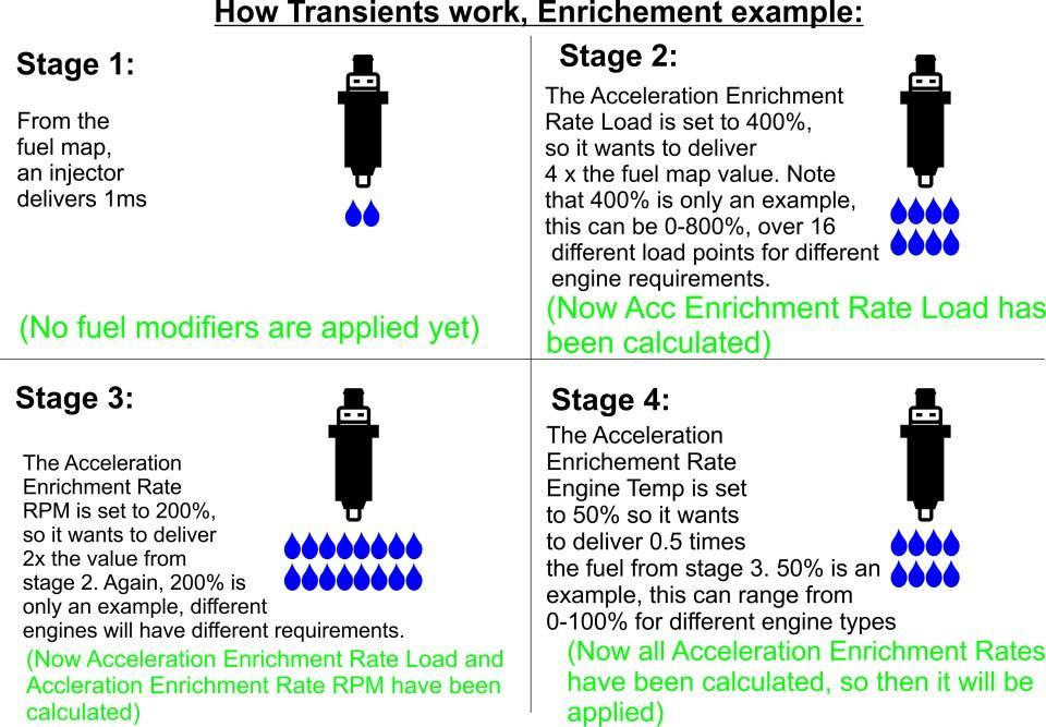
46 V550 OPERATION MANUAL Fuel >> Fuel Modifiers >> Transient In this screen you will see three dials and two buttons. These are related to the text below. Transient is the amount of fuel you want to give the engine on acceleration. Every engine is different and the result of having incorrect transient can be a horrible tune. If you are injecting too much fuel, it will flat spot, blow black smoke and not accelerate. Too little transient will also cause a flat spot, to be lean, backfire out the intake and very sluggish acceleration. Suggestions are turn this off until the tune is complete. If you tune with this on, you could be tuning around it and creating bigger problems. Get the tune correct then turn transients on. This parameter is to help with the sudden opening of the throttle, which is the only time that transient works. On some vehicles you may require a lot of fuel all at once for a short time, other vehicles may require almost no fuel on acceleration. Fuel >> Fuel Modifiers >> Transient >> Acc Enrich Activate Turns Acceleration enrichment on. Fuel >> Fuel Modifiers >> Transient >> Decel Enlean Activate Turns Decel enleanment on. Fuel >> Fuel Modifiers >> Transient >> Acc Enrichment Rate Trim Load: 0% Quick adjustment to the Fuel >> Fuel Modifiers >> Transient >> Acc Enrichment Rate Load graph. This just helps to find if you need more or less in your transient graph at this load point. Fuel >> Fuel Modifiers >> Transient >> Acc Enrichment Rate Trim Load: 50% Quick adjustment to the Fuel >> Fuel Modifiers >> Transient >> Acc Enrichment Rate Load graph. This just helps to find if you need more or less in your transient graph at this load point. Fuel >> Fuel Modifiers >> Transient >> Acc Enrichment Rate Trim Load: 100% Quick adjustment to the Fuel >> Fuel Modifiers >> Transient >> Acc Enrichment Rate Load graph. This just helps to find if you need more or less in your transient graph at this load point. Fuel >> Fuel Modifiers >> Transient >> Acc Enrichment Rate Load This graph is load/percentage increase of the fuel map. At this point you can give the engine up to 800% more fuel than what is in the map. This allows for big throttle or supercharged engines that get a large volume of air on acceleration to have the correct amount of fuel while accelerating. This graph is only working off the load scale as its reference. Page 14
47 Fuel >> Fuel Modifiers >> Transient >> Acc Enrichment Rate RPM This graph is over RPM. It looks at the amount of fuel from the Fuel >> Fuel Modifiers >> Transient >> Acc Enrichment Rate Load graph and multiplies that so it is a simple calculation at this point. 800% in our Fuel >> Fuel Modifiers >> Transient >> Acc Enrichment Rate Load, 50% in our Fuel >> Fuel Modifiers >> Transient >> Acc Enrichment Rate RPM, At this point we only have 400% of fuel going in. If we were to change the Fuel >> Fuel Modifiers >> Transient >> Acc Enrichment Rate RPM, to 200% we would have 1600% going in. Fuel >> Fuel Modifiers >> Transient >> Acc Enrichment Rate Engine Temp Same as the last graph, this looks at both load and RPM graphs and modifies it over engine temperature. Most vehicles require more fuel when cold so get the transients right at operating temperature and then you only need to adjust the Fuel >> Fuel Modifiers >> Transient >> Acc Enrichment Rate Engine Temp. Fuel >> Fuel Modifiers >> Transient >> Acc Enrichment Decay RPM The decay rate is how fast the ECU decays the amount of fuel you are putting into the engine. When a lower number is applied e.g. 2% it decays by 2% every time injector 1 fires so the amount of fuel injected will be present over a long time. If the amount of 80% was used then it is taking 80% away from the transient amount every time injector 1 fires, resulting in this fuel not being there for long. Fuel >> Fuel Modifiers >> Transient >> Decel Enleanment Rate Load On this screen there is a graph in the top half, and a table in the lower half. They are both directly related to each other. Adjusting one will cause the same change in the other. This function adjusts the decel enleanment based on the load at which enleanment is started. This table can be considered the Decel Enleanment base map, as it is the primary source from which the RPM and engine temp tables modify. Engine load is represented on the x axis. The y axis represents the percentage of fuel to be removed from the fuel map under decel enleanment conditions. Fuel >> Fuel Modifiers >> Transient >> Decel Enleanment Rate RPM On this screen there is a graph in the top half, and a table in the lower half. They are both directly related to each other. Adjusting one will cause the same change in the other. This function adjusts the decel enleanment based on the RPM at which the enleanment is started. This table modifies the Decel enleanment rate load table. Page 15
48 V550 OPERATION MANUAL RPM is represented on the x axis. The y axis is a percentage of the percentage in the Decel enleanment rate load table. For example: at a given RPM and load, the decel enleanment load table dictates a percentage ( y axis) of 80% enleanment and the decel enleanment rate RPM table dictates a percentage ( y axis) of 50% then the resulting enleanment would be 40% of fuel removed from the fuel Fuel >> Fuel Modifiers >> Transient >> Decel Enleanment Decay RPM On this screen there is a graph in the top half, and a table in the lower half. They are both directly related to each other. Adjusting one will cause the same change in the other. This adjusts the decel enleanment decay based on the RPM at which the decay is started. Decay dictates the speed in which enleanment is turned off. A higher percentage means that the enleanment will be turned off quickly where a lower percentage will cause the enleanment to turn off more gradually. Page 16
49 Page 17

50 Page 18 V550 OPERATION MANUAL
51 Fuel >> Fuel Modifiers >> Overrun Fuel Cut V550 Operation Manual The purpose of overrun fuel cut is to save fuel. This is done by cutting the fuel to your engine under certain parameters. You set these parameters so that it will only activate under deceleration driving conditions, under a low TPos, over idle RPM and below a certain load parameter. Some vehicles cannot have this activated. Driveline and aggressive motors play a big part in setting this up. If you have a car that cruises on 1100rpm but idles on 1000rpm it is going to be very hard to set this up to work nicely. The other point is that in very heavy traffic where repeated stopping and going is required it may create hunting and/or stalling. Set up properly it will save you fuel, but if the car is set up in a way that it cannot be used do not turn it on. Fuel >> Fuel Modifiers >> Overrun Fuel Cut >> Activate Turns the Overrun Fuel Cut on and does not make it active until parameters are met. Fuel >> Fuel Modifiers >> Overrun Fuel Cut >> Active Below TPos Throttle position that you want the Overrun Fuel Cut to work under. Fuel >> Fuel Modifiers >> Overrun Fuel Cut >> Inactive Above TPos Throttle position that you want the Overrun Fuel Cut not to work above. Fuel >> Fuel Modifiers >> Overrun Fuel Cut >> Active Above Engine Temp The engine temp that you want the Overrun Fuel Cut to work above. It is advised to not have it on when there is any form of engine temperature compensation. Fuel >> Fuel Modifiers >> Overrun Fuel Cut >> Inactive Below Engine Temp The engine temperature you want the Overrun Fuel Cut not to work under. Fuel >> Fuel Modifiers >> Overrun Fuel Cut >> Active Above RPM The RPM point that you want the Overrun Fuel Cut to turn on if all other parameters are met. It will turn on when above the set RPM. Page 19
52 V550 OPERATION MANUAL Fuel >> Fuel Modifiers >> Overrun Fuel Cut >> Inactive Below RPM The RPM point that you want the Overrun Fuel Cut to turn off when all other parameters are met. It will turn off when the RPM is below the set point. Fuel >> Fuel Modifiers >> Overrun Fuel Cut >> Recover Fuel Pulse Activate In some cases the engine requires a small amount of fuel when the Overrun Fuel Cut turns off. Recover fuel can add a small amount of fuel to create a smooth transition from on to off. Fuel >> Fuel Modifiers >> Overrun Fuel Cut >> Recover Fuel Pulse Count The amount of pulses you want the recover fuel to stay for. Fuel >> Fuel Modifiers >> Overrun Fuel Cut >> Recover Fuel Pulse Add on How much extra fuel you wish to add on when the recovery fuel is active? Page 20
53 Fuel >> Fuel Modifiers >> Engine Temperature To run smoothly under cold start condition, most, if not every engine will need this parameter to be set up correctly. Generally an engine requires extra fuel when it is cold and the amount of extra fuel is decreased as the engine approaches its regular operating temperature. It is advised that this is not activated until the base fuel map is correctly tuned at normal operating temperature. This prevents trying to tune around an incorrect compensation. Fuel >> Fuel Modifiers >> Engine Temperature >> Activate This turns the engine temperature compensation table on or off. It is advised that this is not activated until the fuel map is correctly tuned at normal operating temperature. This prevents trying to tune around an incorrect compensation. Fuel >> Fuel Modifiers >> Engine Temperature >> Trims This page has 3 dials. These dials are directly linked to the text values at the bottom half of this screen and you can either type into the text or use the dials. These parameters will make instant changes to the engine temperature compensation table. They cannot be applied directly to the engine temperature compensation table. The Restore button turns the values of the trim dials to 0 all round. Fuel >> Fuel Modifiers >> Engine Temperature >> Trims >> Engine Temperature Comp Trim EngTemp: 0 Trim the amount of Engine Temperature Compensation centred at 0⁰ Engine Temperature. Below 0⁰ the ECU will apply the value that is set here. Above 0⁰ the ECU will interpolate between this and the 50⁰ temperature point. Fuel >> Fuel Modifiers >> Engine Temperature >> Trims >> Engine Temperature Comp Trim EngTemp: 50 Trim the amount of Engine Temperature Compensation centred at 50⁰ Engine Temperature. At 50⁰ the ECU will apply the value that is set here. Above 50⁰ the ECU will interpolate between this and the 100⁰ degree temperature point. Below 50⁰ the ECU will interpolate between this and 0⁰ temperature point. Page 21
54 V550 OPERATION MANUAL Fuel >> Fuel Modifiers >> Engine Temperature >> Trims >> Engine Temperature Comp Trim EngTemp: 100 Trim the amount of Engine Temperature Compensation centred at 100⁰ Engine Temperature. At 100⁰ the ECU will apply the value that is set here. Below 100⁰ the ECU will interpolate between this and the 50 degree temperature point. Fuel >> Fuel Modifiers >> Engine Temperature >> Engine Temperature Compensation Note: It is recommended that this not be used until the fuel map has been tuned at normal operating temperature. On this screen there is a graph in the top half and a table in the lower half. They are both directly related to each other. Adjusting one will cause the same change in the other. This function is used to adjust fuel output under varying engine temperatures. Engine temperature is represented in degrees Celsius on the x axis. The y axis dictates the percentage change in fuel output. A negative percentage will lower the resulting fuel output at the corresponding engine temperature. A positive percentage increases the fuel output at the corresponding engine temperature. When in this table, pressing the x button will adjust the degree of adjustability. The options are visible in the bottom middle of the screen. X axis: 1:1 - Adjustments can be made for every 2⁰ Celsius. X axis: 1:2 - Adjustments can be made for every 4⁰ Celsius. Values will interpolate between adjustable points. X axis: 1:4 - Adjustments can be made for every 8⁰ Celsius. Values will interpolate between adjustable points. X axis: 1:8 - Adjustments can be made for every 16⁰ Celsius. Values will interpolate between adjustable points. Page 22
55 Fuel >> Fuel Modifiers >> Air Temperature V550 Operation Manual To maintain accurate air fuel ratios, most, if not all, engines will need this parameter to be set up correctly. When air increases in temperature, it s density decreases. This means that a change in intake air temp will require a change in fuel output. It is advised that this is not activated until the base fuel map is correctly tuned at normal operating temperatures. Fuel >> Fuel Modifiers >> Air Temperature >> Activate This turns the air temperature compensation table on or off. Fuel >> Fuel Modifiers >> Air Temperature >> Air Temperature Compensation Note: It is recommended that this not be used until the fuel map has been tuned at normal operating temperature. On this screen there is a graph in the top half and a table in the lower half. They are both directly related to each other. Adjusting one will cause the same change in the other. This function is used to adjust fuel output under varying intake air temperatures. Air temperature is represented in degrees Celsius on the x axis. The y axis dictates the percentage change in fuel output. A negative percentage will lower the resulting fuel output at the corresponding engine temperature. A positive percentage increases the fuel output at the corresponding engine temperature. When in this table, pressing the x button will adjust the degree of adjustability. The options are visible in the bottom middle of the screen. X axis: 1:1 - Adjustments can be made for every 2⁰ Celsius. X axis: 1:2 - Adjustments can be made for every 4⁰ degrees Celsius. Values will interpolate between adjustable points. X axis: 1:4 - Adjustments can be made for every 8⁰ degrees Celsius. Values will interpolate between adjustable points. X axis: 1:8 - Adjustments can be made for every 16⁰ degrees Celsius. Values will interpolate between adjustable points. Page 23
56 V550 OPERATION MANUAL Fuel >> Fuel Modifiers >> MAP Sensor This is usually used in setups where a throttle position sensor is used to dictate load, where boost pressure is generated. TPS load indexed setups can also be useful for engines with individual throttle bodies or other engine setups that have low vacuum. Fuel >> Fuel Modifiers >> MAP Sensor >> Activate This turns MAP sensor compensation on or off. Proper configuration of the MAP compensation table is required for this to function correctly. Fuel >> Fuel Modifiers >> MAP Sensor >> MAP Sensor Used This dictates whether the internal MAP sensor, which is suitable up to 30psi, is used, or an external MAP sensor is used. Fuel >> Fuel Modifiers >> MAP Sensor >> MAP Compensation On this screen there is a graph in the top half and a table in the lower half. They are both directly related to each other. Adjusting one will cause the same change in the other. This function is used to dictate the desired fuel compensation at the desired MAP sensor load. The load is represented on the x axis. The y axis represents the percentage of fuel output adjustment, ranging from -100% (no fuel delivered) to 800% (8 times the amount of fuel delivered). When in this table, pressing the x button will adjust the degree of adjustability. The options are visible in the bottom middle of the screen. X axis: 1:1 - Adjustments can be made for every 0.84% load. X axis: 1:2 - Adjustments can be made for every 1.69% load. Values will interpolate between adjustable points. X axis: 1:4 - Adjustments can be made for every 3.37% load. Values will interpolate between adjustable points. X axis: 1:8 - Adjustments can be made for every 6.74% load. Values will interpolate between adjustable points. Page 24
57 Fuel >> Fuel Modifiers >> Battery Voltage V550 Operation Manual Battery voltage compensation is a useful function that can alter the amount of fuel being delivered dependant on battery voltage. This can be used to increase fuel output when battery voltage drops to compensate for a slight lag in injector opening time. It is recommended that this remains off until the fuel map has been tuned at normal operating temperatures. Fuel >> Fuel Modifiers >> Battery Voltage >> Activate Turns the battery voltage compensation table on or off. Fuel >> Fuel Modifiers >> Battery Voltage >> Battery Voltage Compensation Note: It is recommended that this not be used until the fuel map has been tuned at normal operating temperature. On this screen there is a graph in the top half and a table in the lower half. They are both directly related to each other. Adjusting one will cause the same change in the other. This function is used to adjust fuel output under varying battery voltages. Battery voltage is represented on the x axis. The y axis represents milliseconds. A millisecond value of -1 would mean that 1 millisecond would be removed from the injector opening time. A positive millisecond value would add to the injector open time. When in this table, pressing the x button will adjust the degree of adjustability. The options are visible in the bottom middle of the screen. X axis: 1:1 - Adjustments can be made every 0.2 volts. X axis: 1:2 - Adjustments can be made every 0.4 volts. Values will interpolate between adjustable points. X axis: 1:4 - Adjustments can be made every 0.8 volts. Values will interpolate between adjustable points. X axis: 1:8 - Adjustments can be made every 1.6 volts. Values will interpolate between adjustable points. Page 25
58 V550 OPERATION MANUAL Fuel >> Fuel Modifiers >> Special Trim 1 Special trims can be used to make changes in fuel delivery using any input. This includes, but is not limited to: engine temp, RPM, any LS or HS driver and ignition degrees delivered. Fuel >> Fuel Modifiers >> Special Trim 1 >> Activate Turns the special trim 1 on or off. Fuel >> Fuel Modifiers >> Special Trim 1 >> Input Used: This dictates which input is used as the variable for the Special Trim. Fuel >> Fuel Modifiers >> Special Trim 1 >> Special Trim 1 Table On this screen there is a graph in the top half and a table in the lower half. They are both directly related to each other. Adjusting one will cause the same change in the other. This function is used to adjust fuel output in relation to an input of your choosing. Regardless of the input chosen, the y axis will represent the percentage of change of fuel output. This ranges from -50% to 50%. Negative percentages will remove fuel output. Positive percentages will add fuel. The x axis values will vary depending on what input is selected. When in this table, pressing the x button will change the degree of adjustability. The options are visible in the bottom middle of the screen. X axis: 1:1 - The maximum adjustability X axis: 1:2 - Adjustments are spaced twice as far apart and values will interpolate between adjustable points. X axis: 1:4 - Adjustments are spaced 4 times as far apart and values will interpolate between adjustable points. X axis: 1:8 - Adjustments are spaced 8 times as far apart and values will interpolate between adjustable points. Page 26
59 Fuel >> Staged Fuel Injection V550 Operation Manual Staged fuel injection simply means that beside from having a single set of injectors, there are additional injectors that are turned on under certain engine parameters. This can be useful for engines that require large amounts of fuel. Instead of running extremely large injectors (which can sometimes cause problems at idle) it uses one bank of somewhat smaller injectors for low fuel demand situations and then utilise the 2nd bank of injectors when high fuel demands are needed. This screen has 9 buttons and a dial on the top half and 10 options in the bottom half. The buttons and dial are linked to the options below with their corresponding name. Adjusting the values of the button / dials will adjust the values in the options on the lower half. Fuel >> Staged Fuel Injection >> activate Turns staged fuel injection on or off. Fuel >> Staged Fuel Injection >> Overall Trim This offers an overall trim of all the injectors that have been setup for staged injection. This ranges from -50% to 50%. -50% will remove 50% of the injector opening time. 50% will add 50% of the injector opening time. Fuel >> Staged Fuel Injection >> Injector # Staged activate This will cause the respective injector output to be used for staged injection. This will mean that if Injector 8 Staged Activate is set to On, injector output 8 will be used by the Staged Fuel Injection Map. If Injector 7 Staged Activate is set to Off, injector output 7 will be controlled by the base fuel map. Fuel >> Staged Fuel Injection >> Staged Fuel Injection Map This map is set up in the same way as the fuel map, however it only controls injectors that have been selected for staged fuel injection. The values in the cells of this map represent zero to 100% on your delivered injector milliseconds. This map is set up by two parameters X axis & Y axis. The X axis is the horizontal line of your map, in this case it is the RPM scale of your map. When you first open up your map it will be in a 1:1 scale on the X axis, this will be indicated in both the RPM scale being 125 RPM increments and on the bottom tool bar it will indicate that the X axis is at 1:1. Page 27
60 V550 OPERATION MANUAL To increase the RPM parameters, simply push the X button on the keyboard, this will move the scale from 1:1 (125 rpm increments), 1:2 (250 rpm increments), 1:4 (500 rpm increments), 1:8 (1000 rpm increments) & back to 1:1 again. When in a higher scale such as 1:8 and a change is made at one cell e.g rpm, the ECU interpolates and changes the millisecond numbers to the next row showing left, right, up and down. The Y axis is the vertical line of your map. In this case it is the load scale of your map. When you first open up your map it will be in a 1:1 scale on the Y axis, this will be indicated in both the load scale being 16 load increments and on the bottom tool bar it will indicate that the Y axis is at 1:1. To increase the size of the load increments, simply push the Y button on the keyboard, this will move the scale from 1:1 (16 load cells),1:2 (9 load cells), 1:4 (5 load cells) & back to 1:1 again. When in a higher scale such as 1:4 and a change is made at one cell e.g.57% load, the ECU interpolates and changes the fuel injection time to the next row showing left, right, up and down. This allows for a quick fuel map to be made in very short time, extracting back out to finer tuning points allows for more control over the fuel mixture. To adjust the fuel Map, highlight the cell that requires adjustment by left clicking it with the mouse. When a cell is highlighted it turns blue. Using the arrow keys will cause the highlighting to move to the corresponding cell. Pressing the < and > ( less than and greater than ) buttons will change the value of a highlighted cell by 0.4 every time the button is pressed. For a faster change hold The SHIFT key down and the use the < and > keys. This will then change the value by a much greater amount: 6.3 every time. By moving the mouse to the row indicator (this can be either load or RPM) and left clicking the mouse, that line will highlight blue. Now using the < & > keys you can move the whole line up or down in Page 28
61 Ignition >> Ignition Map V550 Operation Manual This is a map that displays ignition timing. The ignition timing is measured in degrees before TDC (Top Dead Centre). This map is set up by two parameters X axis & Y axis. The X axis is the horizontal line of your map, in this case it is the RPM scale of your map. When you first open up your map it will be in a 1:1 scale on the X axis, this will be indicated in both the RPM scale being 125 rpm increments, and on the bottom tool bar it will indicate that the X axis is at 1:1. To increase the RPM parameters, simply push the X button on the keyboard. This will move the scale from 1:1 (125 rpm increments), 1:2 (250 rpm increments), 1:4 (500 rpm increments), 1:8 (1000 rpm increments) & back to 1:1 again. When in a higher scale such as 1:8 if a change is made at one cell e.g rpm, the ECU interpolates and changes the ignition timing to the next row showing left, right, up and down. The Y axis is the vertical line of your map; in this case it is the load scale of your map. When you first open up your map it will be in 1:1 scale on the Y axis, this will be indicated in both the load scale being 16 load increments, and on the bottom tool bar it will indicate that the Y axis is at 1:1. To increase the size of the load increments, simply push the Y button on the keyboard, this will move the scale from 1:1 (16 load cells), 1:2 (9 load cells), 1:4 (5 load cells) & back to 1:1 again. When in a higher scale such as 1:4, if a change is made at one cell e.g.57% load, the ECU interpolates and changes the ignition timing to the next row showing left, right, up and down. This allows for a quick ignition map to be made in very short time, extracting back out to finer tuning points allows for more control over the ignition. To adjust the ignition timing map, highlight the cell that requires adjustment by left clicking it with the mouse. When a cell is highlighted it turns blue. Using the arrow keys will cause the highlighting to move to the corresponding cell. Pressing the < or > buttons will change the value of a highlighted cell by 0.3 degrees every time the button is pressed. For a faster change hold the SHIFT key down and the use the < or >, this will then change the value by a much greater amount; 5.6 degrees every time. Adjustments can also be made by typing the required figure into the selected cell(s). By moving the mouse to the row indicator (this can be either load or RPM), left click the mouse and the line will highlight blue. Now using the < & > keys you can move the whole line up or down in value. By double clicking on the row indicator, a function box will appear in the middle of the map. It will ask for a new value, by entering a value in to this box it will change the entire row to that value. Page 1
62 Ignition >> ignition modifiers >> trims V550 Operation Manual This page has 9 dials, these dials are directly linked to the text values at the bottom half of this screen and you can either type into the text or use the dials. These parameters will make instant changes to the ignition map. They can be left with a + or 10 degrees figure in them or applied to the map. When applied to the map it will change the displayed numbers on the map, returning the dials to 0. If left with a + or 10 degrees figure in these parameters and not applied, the trim will still be active but will not be displayed on the map - this will still make a difference to the actual ignition timing. This can be seen on the right hand side of the dash board. The value under IGN will read differently to what is on the actual ignition map. This section is generally used to see if more or less ignition advance is required in a short time frame. By testing if adding or removing ignition advance in a certain RPM and load band will cause the engine to perform differently. The dials under Ignition >> ignition modifiers >> trims represent 9 different points across load and RPM. Adjusting the trim on one dial will create a major change at that particular load and RPM point and will interpolate to the surrounding points, for example: Adjusting the dial at RPM: 4000 Load: 50% to a trim of +5.1 degrees will add 5.1 degrees of ignition advance to the ignition map at the point 4000 RPM and 50% load, and interpolate the surrounding cells. Ignition >> ignition modifiers >> trims >> overall trim This dial allows for the quick addition or subtraction of up to 30 degrees to the ignition timing over the entire RPM/ load range. This can be useful in the event that the engines compression ratio has been changed so a basic change in ignition timing can be achieved before tuning. If you apply the trim it will change the whole ignition map by the figure required and display the new numbers. If you leave the + or figure in the trim and do not apply it, it will not display the change on the ignition map but will deliver the new amount. This will also be displayed on the right hand side in the dashboard, as IGN will read differently to what is being displayed on the ignition map. Ignition >> ignition modifiers >> trims >> calibration trims This allows for 8 individual igniter trims to be used. This will need to be turned on and ignition to have cycled to be active. We advise that this not be used unless there are definite known requirements or cylinder differences. This would generally be reserved for advanced tuning. This parameter allows for a + or 10 degree difference per ignition output. Page 2
63 It does not change the ignition map figures however it will change the actual delivered ignition timing to the desired ignition output. Each ignition output is affected by the respective ignition calibration trim, for example: If an engine was at idle and had an ignition map value of 10 degrees. A value of -5.1 in the ignition 1 calibration trim will retard the ignition output by 5.1 degrees on ignition output 1. The other ignition outputs would be unaffected and remain at 10 degrees before TDC, where ignition output 1 would have a resulting timing of 4.9 degrees before TDC Ignition >> ignition modifiers >> trims >> trim table The purpose of the trim table is to allow a 3D graph for tuning of mismatched airflow in different cylinders. This is only recommended to be used with the correct tuning equipment. This graph allows for the desired ignition outputs to be turned on and graphed for + or 10 degrees at different load/rpm points. This graph adds or subtracts the amount of ignition timing required in a 3D graph from the original ignition map. If a manifold is not flowing correctly at low RPM and improves as the RPM and airspeed increase, you can then trim the ignition outputs that need trimming to keep a perfect tune. Ignition >> ignition modifiers >> trims >> ignition trim table activate Turns on the ignition trim table to allow selected injectors to be adjusted using the ignition trim table. Ignition >> ignition modifiers >> trims >> Ignition # trim table activate ( # representing the desired ignition output number) On will cause the specified ignition output to operate under the conditions set in the trims table. Off will cause the desired output to perform as per the ignition map. Page 3
64 Ignition >> Ignition Modifiers >> Starting V550 Operation Manual On the top half of this screen there are 3 dials. These correspond to the text on the bottom half of the screen. Changing the value of a dial will change the value of the corresponding text and vice versa. Ignition >> Ignition Modifiers >> Starting >> Start Ignition Timing EngTemp: 0 This function will adjust the ignition timing under starting conditions by the indicated value. This ranges from -11.3⁰ (retards ignition by 11.3⁰) to 78.4⁰ (advances ignition 78.4⁰). This will change the ignition timing at 0 ⁰ Celsius to the selected value and will interpolate above to the value at 50⁰ Celsius. Ignition >> Ignition Modifiers >> Starting >> Start Ignition Timing EngTemp: 50 This function will adjust the ignition timing under starting conditions by the indicated value. This ranges from -11.3⁰ (retards ignition by 11.3⁰) to 78.4⁰ (advances ignition 78.4). This will change the ignition timing at 50⁰ Celsius to the selected value and will interpolate to the selected values at 0 and 100⁰ Celsius. Ignition >> Ignition Modifiers >> Starting >> Start Ignition Timing EngTemp: 100 This function will adjust the ignition timing under starting conditions by the indicated value. This ranges from -11.3⁰ (retards ignition by 11.3⁰) to 78.4⁰ (advances ignition 78.4 ⁰). This will change the ignition timing at 100⁰ Celsius to the selected value and will interpolate below to 50⁰ Celsius. Page 4
65 Ignition >> Ignition Modifiers >> Engine Temperature This function allows the user to set changes to ignition timing in relation to engine temperature. Ignition >> Ignition Modifiers >> Engine Temperature >> Activate This turns the engine temperature ignition compensation table on or off. Ignition >> Ignition Modifiers >> Engine Temperature >> Active Above RPM This sets the minimum RPM value that the engine temperature ignition compensation table will be active above. This can be used to prevent the table from making changes to ignition timing at idle or under starting conditions. Ignition >> Ignition Modifiers >> Engine Temperature >> Engine Temperature Compensation On this screen there is a graph in the top half and a table in the lower half. They are both directly related to each other. Adjusting one will cause the same change in the other. This function is used to adjust ignition timing output under varying engine temperatures. Engine temperature is represented in degrees Celsius on the x axis. The y axis dictates the change in degrees BTDC (Before top Dead Centre) and ranges from - 45⁰ (retards ignition timing) to 44.6⁰ (advances ignition timing). When in this table, pressing the x button will adjust the degree of adjustability. The options are visible in the bottom middle of the screen. X axis: 1:1 - Adjustments can be made every 2⁰. X axis: 1:2 - Adjustments can be made every 4⁰. Values will interpolate between adjustable points. X axis: 1:4 - Adjustments can be made every 8⁰. Values will interpolate between adjustable points. X axis: 1:8 - Adjustments can be made every 16⁰. Values will interpolate between adjustable points. Page 5
66 Ignition >> Ignition Modifiers >> Air Temperature V550 Operation Manual This function allows the user to set changes to ignition timing in relation to intake air temperature. Ignition >> Ignition Modifiers >> Air Temperature >> Activate This turns the air temperature ignition compensation table on or off. Ignition >> Ignition Modifiers >> Air Temperature >> Active Above RPM This sets the minimum RPM value that the air temperature ignition compensation table will be active above. This can be used to prevent the table from making changes to ignition timing at idle or under starting conditions. Ignition >> Ignition Modifiers >> Air Temperature >> Air Temperature Compensation On this screen there is a graph in the top half and a table in the lower half. They are both directly related to each other. Adjusting one will cause the same change in the other. This function is used to adjust ignition timing output under varying air temperatures. Air temperature is represented in degrees Celsius on the x axis. The y axis dictates the change in degrees BTDC and ranges from -45⁰ (retards ignition timing) to 44.6⁰ (advances ignition timing). When in this table, pressing the x button will adjust the degree of adjustability. The options are visible in the bottom middle of the screen. X axis: 1:1 - Adjustments can be made every 2⁰. X axis: 1:2 - Adjustments can be made every 4⁰. Values will interpolate between adjustable points. X axis: 1:4 - Adjustments can be made every 8⁰. Values will interpolate between adjustable points. X axis: 1:8 - Adjustments can be made every 16⁰. Values will interpolate between adjustable points. Page 6
67 Ignition >> Ignition Modifiers >> Special Trim 1 Special trims can be used to make changes to ignition timing using any input. This includes, but is not limited to: engine temp, RPM, any LS or HS driver and ignition degrees delivered. Ignition >> Ignition Modifiers >> Special Trim 1 >> Activate Turns the special trim 1 on or off. Ignition >> Ignition Modifiers >> Special Trim 1 >> Input Used This dictates which input is used as the variable for the Special Trim 1. Ignition >> Ignition Modifiers >> Special Trim 1 >> Special Trim 1 Table On this screen there is a graph in the top half and a table in the lower half. They are both directly related to each other. Adjusting one will cause the same change in the other. This function is used to adjust ignition timing output in relation to an input of your choosing. Regardless of the input chosen, the y axis will represent the change in ignition timing in degrees BTDC (Before Top Dead Centre). This ranges from -45⁰ (retards ignition timing) to 44.6⁰ (advances ignition timing). The x axis values will vary depending on what input is selected. When in this table, pressing the x button will change the degree of adjustability. The options are visible in the bottom middle of the screen. X axis: 1:1 - The maximum adjustability. X axis: 1:2 - Adjustments are spaced twice as far apart and values will interpolate between adjustable points. X axis: 1:4 - Adjustments are spaced 4 times as far apart and values will interpolate between adjustable points. X axis: 1:8 - Adjustments are spaced 8 times as far apart and values will interpolate between adjustable points. Page 7
68 Ignition >> Ignition Modifiers >> Rotary Trailing Ignition Split When selecting the ignition outputs to be rotary mode, this option allows for a timing split between leading and trailing. In this folder you can set the desired amount of timing split you want. Ignition >> Ignition Modifiers >> Rotary Trailing Ignition Split >> RPM Table On this screen there is a graph in the top half and a table in the lower half. They are both directly related to each other. Adjusting one will cause the same change in the other. This function allows you to set the desired ignition split over RPM. The x axis represents RPM, while the y axis represents degrees BTDC. When in this table, pressing the x button will adjust the degree of adjustability. The options are visible in the bottom middle of the screen. X axis: 1:1 - Adjustments can be made every 125 RPM. X axis: 1:2 - Adjustments can be made every 250 RPM. Values will interpolate between adjustable points. X axis: 1:4 - Adjustments can be made every 500 RPM. Values will interpolate between adjustable points. X axis: 1:8 - Adjustments can be made every 1000 RPM. Values will interpolate between adjustable points. Set the desired amount of timing split you want. Ignition >> Ignition Modifiers >> Ignition Lock Ignition lock is a particularly useful function in the event that the user needs to check or adjust the engines ignition timing. Ignition lock will simply keep the engines ignition locked to the selected timing in degrees BTDC (Before Top Dead Centre). The reason this is handy is it prevents the Wolf ECU from changing the ignition timing through ignition modifiers or from imperfections in the map, giving the user confidence when setting ignition timing. Ignition >> Ignition Modifiers >> Ignition Lock >> Activate This turns the ignition lock on or off. Ignition >> Ignition Modifiers >> Ignition Lock >> Ignition Lock Fixed Timing This sets the ignition timing the user wants to have the ECU locked to. Page 8
69 Control >> General Functions >> Thermo Fan The ECU can control an electric thermo fan. Vehicles can be set up with a primary thermo fan with the option for one or more secondary fans and or A/C condenser fans. Control >> General Functions >> Thermo Fan >> Activate Primary Thermo Fan on A/C Having this set to on will cause the primary thermo fan output to be activated when there is an input to the A/C request. Control >> General Functions >> Thermo Fan >> Active Above Engine Temp This sets the engine temperature that will cause the primary thermo fan to turn on. This value or above will keep the fan on. Control >> General Functions >> Thermo Fan >> Hysteresis The hysteresis allows a value to be made that will act as a gap between switching on and switching off at the nominated active above engine temp. This prevents the thermo fan from rapidly switching on and off. Control >> General Functions >> Thermo Fan >> Activate A/C Thermo Fan When on, this activates the selected pin (see next description) to control a secondary thermo fan. Control >> General Functions >> Thermo Fan >> A/C Thermo Fan Controlled Pin This dictates which pin will be used as the output for the secondary thermo fan. Control >> General Functions >> Thermo Fan >> Activate Secondary Thermo Fan Above EngTemp This sets the engine temperature that the secondary thermo fan will be turned on. It is turned on when the temperature is above the set value. Control >> General Functions >> Thermo Fan >> Hysteresis This has the same function as the above hysteresis, but is for the secondary fan. Page 1
70 Basic wiring diagram of a twin thermo fan setup Page 2
71 Control >> General Functions >> Fuel Pump V550 Operation Manual The Wolf V550 has a dedicated fuel pump control output. Control >> General Functions >> Fuel Pump >> Activate When on, activates the dedicated fuel pump control output. This will activate the fuel pump control output when the key is on for a brief moment (see next description) and while the engine is running. Control >> General Functions >> Fuel Pump >> Initial Activation Seconds This dictates the number of seconds that the fuel pump will prime when the ignition is turned on. This prevents the fuel pump being active when the engine is not running, particularly for safety in the event of a fire. Control >> General Functions >> Fuel Pump >> Force HL6 High When Fuel Pump Driven On In some cases a high side fuel pump driver is required. Turning this on will activate HL6 and drive it high when fuel activation is activated. Basic wiring schematic for fuel pump: Page 3
72 Control >> General Functions >> Idle Lock V550 Operation Manual This function is designed for engines that are having difficulties idling. This can be due to large camshafts, low manifold vacuum, poor fuelling etc. This parameter allows you to lock the idle setting and give a desired amount of fuel and ignition without alterations no matter what happens to load or RPM within the desired specifications. This can calm an aggressive idle to be manageable. Example: To work under 1200RPM, Below 1.2 TPOs, don t work above 1300RPM or TPOS of 2. Control >> General Functions >> Idle Lock >> Activate On will turn the idle lock on and work when in the desired parameters, this will also be shown in the right hand side of the dashboard, it will light up idle lock. Control >> General Functions >> Idle Lock >> Active Below RPM The desired RPM you wish for idle lock to be used under, if you have an aggressive idling motor you may want this to be slightly higher than your targeted RPM. Control >> General Functions >> Idle Lock >> Inactive Above RPM The RPM you want the idle lock not to work above, if at any point the RPM goes above this point while in idle lock it will turn the idle lock off, this should be set within a 200 RPM of your active below settings. Control >> General Functions >> Idle Lock >> Active Below TPos This setting should be as low as possible so that the idle lock will only work when closed throttle is achieved. Control >> General Functions >> Idle Lock >> Inactive Above TPos This setting is to disable the idle lock above the desired TPOs setting. Control >> General Functions >> Idle Lock >> Delivered Fuel The amount of fuel you wish to give the engine while idle lock is active. Control >> General Functions >> Idle Lock >> Delivered Ignition The amount of ignition timing you wish to give the engine while idle lock is active. Page 4
73 Control >> General Functions >> Rev Limit V550 Operation Manual This function is to allow the over revving of your engine. There are many different times you may want to limit the RPM of your engine, e.g. different fuels being used, different amount of boost, launch control, 2 stage, also Valet mode (this is when you want to leave your car with someone you do not trust so you can limit the RPM on them.) We have four RPM modes. These can be selected to be used at different times e.g.: when activated by switches or by other parameters in our program. You can setup one rev limit as an overall rev limit. Then set one up to be a valet mode activated by a switch and another to be the rev limit for launch control when activated. Control >> General Functions >> Rev Limit >> Rev Limit Main Allows another form of rev limiting that can be activated via a switch or the program. Control >> General Functions >> Rev Limit >> Rev Limit - Main >> Activate On allows the primary rev limit to be active when desired parameters are met. Control >> General Functions >> Rev Limit >> Rev Limit - Main >> Rev Limit RPM Maximum RPM you want the engine to rev to, your engine will not rev past this point. Control >> General Functions >> Rev Limit >> Rev Limit - Main >> Rev Limit Mode There are four different modes to be selected: Hard Cut Fuel: this will cut the fuel only on all injectors at the desired RPM Hard Cut Ignition: this will cut the ignition on all ignition outputs at the desired RPM. Hard Cut Both: this will cut both fuel and ignition on all injector and ignition outputs at desired RPM. Soft Cut Ignition: this will cut individual ignition events (as per described below). This will cut the desired ignition events in a random pattern, to limit the engines RPM in a soft function. Random rolling is to ensure each firing is cut safely. Page 5
74 Control >> General Functions >> Rev Limit >> Rev Limit - Main >> Soft Rev Limit On/off. This also has four other options to be selected: Cut 1 in 8: this will cut one ignition event in every eight, this is a very soft rev limit and can be driven through if tried. Cut 2 in 8: this will cut two ignition events in every eight, this will do the opposing firing events and will limit most vehicles at this point. Cut 4 in 8: this will cut four ignition events in every eight, this being still soft it will limit most high powered vehicles at this point without the harsh hard rev limit effects. Cut 6 in 8: this is for very high powered vehicles that are trying to limit RPM. When producing high power at these points it will cut six in every eight ignition events. It has a random starting roll and will mathematically select the next event to be cut. Control >> General Functions >> Rev Limit >> Rev Limit - Main >> Soft Rev Limit Hard Cut RPM The RPM limit that you want to hit if the engine drives past your desired soft cut e.g.: soft cut at 3000RPM then hard cut at 3400RPM Control >> General Functions >> Rev Limit >> Rev Limit - Main >> Tacho Red Line (indicative) This sets the Red line on the dashboard on the right hand side. It has no other function apart from visual to indicate to the tuner that you are near the desired red line. Control >> General Functions >> Rev Limit >> Rev Limit - Main >> Tacho Yellow Line (indicative) This sets the yellow line on the dashboard on the right hand side. It has no other function apart from visual to indicate to the tuner that you are near the desired yellow line. Page 6
75 Control >> General Functions >> AirCon Control This parameter allows for trims to be added when the A/C is activated, some engines require more fuel or timing to help stabilize the idle and give correct emissions. This parameter generally only takes effect at idle and is turned off as acceleration is applied. There is a secondary parameter to this WOT control this allows control of the A/C relay so that it can be turned off at high loads, stopping the risk of a/c system damage. Control >> General Functions >> AirCon Control >> Activate Allows activation of the trims to be used when the activation of the A/C request is engaged. Control >> General Functions >> AirCon Control >> Fuel Trim when Active The desired enrichment required when the A/C is on, this is a trim and is in percentage on the delivered fuel amount. Control >> General Functions >> AirCon Control >> Ignition Trim when Active The desired amount of increase in ignition timing when the A/C is on. Generally this can be a couple of degrees to help with the extra load on the engine. Control >> General Functions >> AirCon Control >> Disabled Above Load The load you want to turn the extra trims off at. Normally set this about 10 load points higher than were the engine idles at. This will stop the trims turning on and off if a slight hunt occurs. Control >> General Functions >> AirCon Control >> Disabled Above Throttle Position The Throttle Position that you want the trims to turn off at. Normally set to about 5 higher than you have your throttle set to at idle. This allows for some movement in the throttle before the trims turn off. Page 7
76 Control >> General Functions >> AirCon Control >> Disabled Above RPM Turns the trims off above this RPM. Suggested about 500 RPM above idle RPM. Control >> General Functions >> AirCon Control >> AirCon Request Sense on 0V Input The input to the Wolf ECU can accept either 12v or 0V to indicate that the A/C has been activated. This allows you to select 0V switching. The input from the A/C switch is switching to ground. With this parameter left off it is looking for a 12V switch input. Control >> General Functions >> AirCon Control >> Wide Open Throttle Control (WOT) WOT control is to allow activation of a relay to control the A/C compressor. This relay may need to be turned off for a number of reasons - the most obvious is engine speed and load. With this parameter we allow you to set the load and RPM that you want the A/C to work between and also have other inputs such as pressure switches to take into account. When the A/C input is activated it then looks at what needs to be turned on e.g.: fans, idle speed, WOT control pin. This is all done in such a way that it does not create load on the engine. The A/C request is turned on, the idle will step up if active. The WOT pin grounds after the desired time and then the fans switch on, all of this can be seen on the dashboard on the right hand side. Control >> General Functions >> AirCon Control >> Wide Open Throttle Control (WOT) >> WOT Activate Allows the operation of the WOT control pin. Not all vehicles require this parameter. Control >> General Functions >> AirCon Control >> Wide Open Throttle Control (WOT) >> WOT A/C Controlled Pin The pin you wish to ground to control the A/C when all parameters are met. Page 8
77 Control >> General Functions >> AirCon Control >> Wide Open Throttle Control (WOT) >> WOT A/C Clutch Engage Delay This is the delay that you request between A/C request being activated and the grounding of the WOT control pin. This time allowing for the idle speed to build up, this section is as follows: 10 = 1 sec. 20 = 2 sec. Control >> General Functions >> AirCon Control >> Wide Open Throttle Control (WOT) >> WOT Controlled Pin Output Polarity Do you want it to work over selected parameters or up to selected parameters? Normal: work over selected parameters. Reverse: work up to selected parameters. Control >> General Functions >> AirCon Control >> Wide Open Throttle Control (WOT) >> WOT Disable A/C above Load Allows to be turned off above a certain load point. You want this set to a high load point so that the A/C is not turning on/off on acceleration, e.g.: if a force fed car that is running 20PSI boost may get 3 PSI on an acceleration to pass a car, so you don t want the A/C to turn off at this point - so set the A/C load higher than this let s say load 65%. Control >> General Functions >> AirCon Control >> Wide Open Throttle Control (WOT) >> WOT Disable A/C above Throttle Position The throttle position that you want the A/C to stop working at. As per the previous section you do not want the ac to turn off too early. On most soft to med accelerations, the throttle does not pass 85% throttle. If set to 85% then the throttle has to pass this before it turns the A/C off. Control >> General Functions >> AirCon Control >> Wide Open Throttle Control (WOT) >> WOT Disable A/C above RPM The RPM that you want the A/C to stop working. This will vary depending on the type of engine but a general rule is about 1000 RPM less than desired rev limit. Page 9
78 Control >> General Functions >> AirCon Control >> Wide Open Throttle Control (WOT) >> WOT Disable A/C below RPM This allows for the A/C not to be working below a desired RPM. This helps with starting of the engine while the A/C is switched on. It is also useful if under shoot happens on decel, normally set 200 rpm under desired idle speed. Control >> General Functions >> AirCon Control >> Wide Open Throttle Control (WOT) >> WOT External Activation By Allows an external source to be used as well as the A/C request. User defined on what pin they use, but as an example we will use LS1 (this could be wired up to a pressure switch or even a cabin temperature switch). Control >> General Functions >> AirCon Control >> Wide Open Throttle Control (WOT) >> WOT External Activation Switch Point As the pin we have selected is LS1 for the example, this can be calibrated to read any figure we want (see LS inputs). Let s say we have calibrated it to pressure, so turn off at 550kpa pressure. This is the activation point. Control >> General Functions >> AirCon Control >> Wide Open Throttle Control (WOT) >> WOT External Activation Hysteresis As per our example we are using pressure so we want it to turn off at 550kpa but back on as the pressure drops, 30kpa less therefore our hysteresis will be 30. Control >> General Functions >> AirCon Control >> Wide Open Throttle Control (WOT) >> WOT External Input Polarity As per our example we are using pressure to turn the A/C off (don t want to over pressure the A/C) so our polarity will be reversed, works up to pressure point then turns off. Normal would mean it turns on over this point. Page 10
79 Control >> General Functions >> Shift Light V550 Operation Manual This function allows for one or more lights to set off at different RPM. You can have six solid functions at different RPM. You can use one as a pre warning and then the final stage to flash. These can also be used to drive different things that you may want driven only over a certain RPM. As an example, the operation of three lights may be as such - one comes on at 3000 RPM to let you know to get ready to change. The next comes on at 4000 RPM as a reminder and that RPM is much closer now and finally at 5000 RPM time to change gear. Control >> General Functions >> Shift Light >> Light Stage 1 Control >> General Functions >> Shift Light >> Light Stage 1 >> Activate On/Off Activates this mode if required. Control >> General Functions >> Shift Light >> Light Stage 1 >> Trip RPM Sets the RPM that you wish to ground the desired pin at. Control >> General Functions >> Shift Light >> Light Stage 1 >> Controlled Pin Shift light 1 will control the desired pin that has been selected. Control >> General Functions >> Shift Light >> Light Flash Point This will flash any light that is being activated at this point by the shift light mode. Control >> General Functions >> Shift Light >> Light Flash Point >> Activate On / Off activates the flashing of the lights. Control >> General Functions >> Shift Light >> Light Flash Point >> Flash Above RPM The RPM that you want the lights to be flashing above. Page 11
80 Control >> General Functions >> Stepper Motor (Aux HL1-4) This is where you set up the drivers for the HL1-4. The HL1-4 is our dedicated stepper motor drivers. If you are using them as a stepper motor driver then this parameter needs to be filled in. There are lots of different applications that stepper motors are used for - not just as idle. For example, one can be used to drive the oil pump on a rotary. If you are using HL1-4 as normal outputs, then leave this turned off. Control >> General Functions >> Stepper Motor (Aux HL1-4) >> Activate On / Off turns the HL1-4 to a stepper motor driver. Control >> General Functions >> Stepper Motor (Aux HL1-4) >> Stepper Control Value Source As previously described, you can use the HL1-4 for many controllers. Most common is as idle speed, but can also be driven from a multi-controller also. If controlling from a multi-controller the Multicontroller section must be filled out. Control >> General Functions >> Stepper Motor (Aux HL1-4) >> MultiController Source Setup As per idle speed, when using the HL1-4 as the idle device, you have to set up the parameters you want the stepper motor to work in. Control >> General Functions >> Stepper Motor (Aux HL1-4) >> MultiController Source Setup >> Step Speed This is the speed that you want the idle speed to work at. If you try to make the stepper motor work quicker than it can it will skip steps. Hence, a good starting point is 1.2 for most stepper motors. Page 12
81 Control >> General Functions >> Stepper Motor (Aux HL1-4) >> MultiController Source Setup >> Step Size Multiplier The step size multiplier can be used for a stepper motor that has more than 256 steps. This is not often used, as most stepper motors have a step range of less than 255 steps. A suggested value is 0. Control >> General Functions >> Stepper Motor (Aux HL1-4) >> MultiController Source Setup >> Direction to Open The stepper motor control signals can be conveniently reversed if the motor is stepping backwards to the intended direction. Suggested setting is normal (forward). Control >> General Functions >> Stepper Motor (Aux HL1-4) >> MultiController Source Setup >> Reset Speed This is how fast the stepper motor resets itself back to the desired position. The lower the number the faster it resets. The larger the number the slower it returns. Suggested value is 1.2. Control >> General Functions >> Stepper Motor (Aux HL1-4) >> MultiController Source Setup >> Reverse Step Init Activate A stepper motor should be initially stepped in reverse to its physical start point when the ECU is powered up. This is to ensure the position of the stepper motor is the same every time the ECU is powered up. It is suggested this is turned on. Control >> General Functions >> Stepper Motor (Aux HL1-4) >> MultiController Source Setup >> Reverse Steps on Initialisation This should be greater than the number of steps required by the stepper motor to do a full travel. Most stepper motors are between steps. Set this to 250 steps. Page 13
82 Control >> General Functions >> On-Vehicle Communications Some vehicles require a data stream to run their dash board. If you wish to use this feature, you will require the extra hardware to go in-line with this parameter. This can be purchased from your local Wolf Dealer. Control >> General Functions >> On-Vehicle Communications >> Activate When on, will activate a data stream to be forwarded out on pin B25 automatically. Control >> General Functions >> On-Vehicle Communications >> On-Vehicle Communications Type Select the vehicle type you are installing the Wolf ECU onto. Control >> General Functions >> Test Output Pins After you have installed the Wolf ECU into your project, you may want to check that you have everything working as it should. This handy function allows you to test individual pins to see if they are connected. Control >> General Functions >> Test Output Pins >> Activate On / Off, remember after testing to turn this parameter OFF. Control >> General Functions >> Test Output Pins >> Select Output Pin to Test Choose which output pin you wish to test. The ECU will pulse the output pin 3 times per second. Injector outputs will pulse for the number of milliseconds that the starting fuel is set to. Ignition outputs will pulse for the current coil charge time. Auxiliary outputs will pulse at 50% duty cycle. Page 14
83 Control >> Idle Speed V550 Operation Manual Idle speed allows you to set almost any idle speed device and set it as per factory settings. If you take the time and read through this section it is very complex but can make the difference between a nice tune and a perfect tune. Some of the biggest problems that we see are to do with idle speed, not having the parameters set correctly is one of the most common. Basic wiring schematic for PWM Idle Air Speed device: Control >> Idle Speed >> Trims This area is for a quick adjustment after the idle speed has been set up and proven to be working, it is for testing if more or less idle speed is required. Control >> Idle Speed >> Trims >> Target RPM Trim EngTemp: 0 Adjusts the idle speed at set temperature, this will interpolate to higher and lower temperatures. Page 1
84 Control >> Idle Speed >> Trims >> Target RPM Trim EngTemp: 50 Adjusts the idle speed at set temperature, this will interpolate to higher and lower temperatures. Control >> Idle Speed >> Trims >> Target RPM Trim EngTemp: 100 Adjusts the idle speed at set temperature, this will interpolate to higher and lower temperatures. Control >> Idle Speed >> Target RPM Engine Temp This is a 2D graph RPM/Engine temp. You set the targeted RPM at what engine temperature you require. Keep in mind that most engines require more idle speed when cold. Another point to look at is as you open the idle valve when cold, it will not rev up if you are not giving it enough fuel. Keep this in mind when setting up the idle device as when you increase fuel, your idle opening may be too much. You can make changes to this graph by increasing and decreasing the set RPM in the bottom text screen. You can minimise and maximise the graph by using the x button and adjustments can be made by typing in the RPM or using < or >. If you wish to get a starting point, double click on the word RPM in the grey box. This will bring up a dialog box that asks you for a new value. Type in the new value and hit enter. This will put the desired RPM across the whole graph, now you can work the graph from there. Control >> Idle Speed >> Initial Centre Engine Temp This is how far open the idle speed device is when not being used while driving or accelerating. The idle speed device must be given a value even when not in the idle parameter s, this is its initial centre. This helps with a number of problems. When getting off the throttle, the idle speed is already open so it catches the idle and brings the idle down to stop under shooting. It allows you to set the initial centre so that when it is cold you have the range on the idle speed device to create a high idle for clean idling when cold. It allows for A/C add on to compensate for A/C being turned on. Once the motor is running, set the initial centre to be slightly higher than what it is taking to idle the engine. What this means is you have the engine running, you have checked ignition timing and mixtures. On the right side in the dashboard there is an idle indicator, when the engine is warm you want this to read around 20-30%, this means it is taking 30% of the idle speed to run at idle. If this is an aftermarket throttle body or the engine has been modified then you may have to adjust the throttle or air bleed. Don t forget that if you adjust throttle, you need to adjust the TPos settings back to zero. Page 2
85 Now let s say you have the engine running at 20% idle, you will want to set you initial centre to about 28% (different idle speed devices will be different settings). This means when you accelerate, the idle speed device will open up to 28% and as you close the throttle, it will hold the RPM up and then slowly bring the RPM down to desired amount. If the RPM is holding up too high, lower the amount in the initial centre. If not high enough, increase the initial centre. Be aware that if the RPM is holding up then it may be that you have not gone too high in RPM but is holding up due to increase ignition timing in the ignition map. Control >> Idle Speed >> Activation Control >> Idle Speed >> Activation >> Activate ON / OFF - if off is selected then the idle speed device will go to the initial centre and stay there. Control >> Idle Speed >> Activation >> Lower Inactive Below RPM Below what RPM do you not want the idle speed to work? At this point it will go back to the initial centre. Normally, this is set to around 30 RPM but keep in mind this can help in certain cases, for example if engines were undershooting which happens due to big cams, low manifold vacuum. If you set this to be 100RPM below the targeted RPM, this undershoots it, turns off and the idle speed device goes to the initial centre. This causes the idle to pick up and not stall. Control >> Idle Speed >> Activation >> Lower Active above RPM To be set above your lower inactive below point. Point that you require the idle speed to work above this RPM. Control >> Idle Speed >> Activation >> Higher Active below RPM This is the RPM that you want the idle speed to stop working at. If this is set to 2000 RPM, as you accelerate past 2000RPM the idle speed, device will go to the initial centre. Be aware that if this is set too low or too high you can have problems. It is too low if you start the car up when cold and you have extra opening turned on. It revs up and goes past this point then it is going to go to its initial centre which may at this point hold it above the higher activation point so it will not come down from this point. If you have it set too high, let s say 4000RPM, and you are slowing down through the gears pulling up at a set of lights, TPos is closed but the engine is being held up in RPM by the gearbox. The ECU is going to think that it needs to slow the motor down so it will close the idle speed device as you come to a stop. The engine almost stalls due to a closed idle speed so this needs to be set just above the highest RPM you will be seeing when starting the vehicle (this is normally cold). Page 3
86 Control >> Idle Speed >> Activation >> Higher Inactive Above RPM Should be set 200RPM above higher active point. Control >> Idle Speed >> Activation >> Active Below TPos The TPos point that you want the idle speed to work under. Set this as low as possible e.g.: 1.2 but if you have a TPos or throttle body that moves as it heats up you may have to increase this out to 5. Control >> Idle Speed >> Activation >> Inactive Above TPos Make this slightly greater than Active below TPos setting. Control >> Idle Speed >> Activation >> Activate with Vehicle Speed Let s you have an input from wheel speed. If you have a speed input it is a good idea to use this, as previously explained one big issue you may come up against is in a manual car changing down and slowing to a stop using the gears. By having a speed input in we can say don t work until under desired speed let s say 10km/h, that way the idle speed will stay at its initial centre and not move until you are almost stopped. Control >> Idle Speed >> Activation >> Active Below Vehicle Speed The speed you want the idle speed device to start working. Control >> Idle Speed >> Activation >> Inactive Above Vehicle Speed The Speed you want the idle speed to stop working. Control >> Idle Speed >> Tracking This folder contains the various settings for the speed at which the idle control device tracks. Control >> Idle Speed >> Tracking >> Tracking Dead RPM Band The dead band is a section of RPM in which the idle speed device will not change. If you have 40 in here it will allow the RPM to wander 20 RPM either side of the targeted RPM before it starts to track. If you have this band set too narrow, hunting can occur as the idle speed tracks into and out of the dead band. Have this band too wide and erratic idle control will happen e.g.: idle one time at 900rpm the next time at 700rpm. Suggested value is but keep in mind this can be opened up if required. Page 4
87 Control >> Idle Speed >> Tracking >> Tracking Normal RPM Band This is the band that outside the dead band, the idle speed device is going to move at its normal speed, normally around 180RPM. This means 90RPM either side of your targeted RPM, the idle speed will move at its normal speed and track back to the desired RPM slowly. Outside these parameters the idle speed is working at fast speed (explained below). Control >> Idle Speed >> Tracking >> Tracking Normal Speed This will depend on what idle speed device you have. A starting point would be 20. Note: The greater the number the slower the speed. Control >> Idle Speed >> Tracking >> Tracking Fast Speed Tracking fast speed is used when RPM is out of the Normal RPM Band. This will make more rapid changes towards the desired idle RPM. The required value will depend on what idle speed device you have. A starting point would be 9. Note: The greater the number the slower the speed. Control >> Idle Speed >> Tracking >> Tracking Reset Speed This is the speed that the idle device resets itself to the initial centre. On a PWM device this can be as low as 0.4, on a stepper motor as low as 1.2. Control >> Idle Speed >> Tracking >> Tracking Step Size This allows you to set the amount of steps your idle device takes every time it makes a move. As an example, if I had a device that took 255 steps from open to close and my step size was.4, it would take a long time to travel the whole range. If I had the step size set to 1.2 we have now tripled the range from the previous setting and still have good control over the device. If I set it to 5, this would be faster because every movement the device makes is 5 steps but fine idle control can be a problem and it may require that for a steady idle. Suggested value: Page 5
88 TARGETED RPM FAST SPEED NORMAL SPEED DEAD BAND NORMAL SPEED FAST SPEED DEAD BAND =60 rpm = 30 either sideof thetargetedrpm, idle device will not work TIP if dead band is set to small hunting may occur due to idle speed device trying to regain and ntain mai a perfect rpm, if dead band is set to high a big variance is allowed from the targeted rpm and unstable idle control can happen. NORMALSPEED = 180 rpm = 90 rpm either side of targeted rpm-30 rpm dead band, idle device works in normal speed Tip set normal band wide enough so that it allows catching of the rpm on decel so under shooting does not occur, ou ydo not want the dead band and the normal band to be to close, you need to give the idle speed device room to work, lets say 100 rpm, this will work slowly inside this parameter and work its way to the targeted rpm. Setting this to wide will cause a very slow reduction back to idle, and having e th feeling of a idle hang up. FAST SPEED operates out side normal speed range idle speed will operate at fast speed to regain idle rpm Tip set fast speed to bring idle device back to with in an operating range so that the idle device an chave constant control of the idle. If set to fast can cause over shooting to happen and a hunt or stalling to occur, if set to slow it may not bring the idle down ast fenough on a decel and hang the idle up for a long time. Control >> Idle Speed >> Limits Limits are created for two reasons. You may have a device that needs to be limited for correct use. For example, Mazda MX5 idle speed device has a built in limp home mode. If this device loses power to it, it shuts all the way. What this really does is open the valve by 30%. This is really interesting if you are trying to control this valve. Your engine will slow down like expected and then as the valve keeps closing the engine will speed up confusing both you and the ECU. What we do is put a minimum clip on this which does not allow it to close more than 30%. The same can be said for over opening some idle valves, they only need to be opened 50% of the way. If they open too far they lose their way and do not know how far they are open, so in this case we put a maximum clip of 50% If you are wanting to test your idle device, you can use the min/max clips and move the device to the desired area and have it stable, not hunting around. This is ideal if you are trying to bring the idle amount down by means of opening up an air bleed or moving a throttle plate. Keep reducing the clip values until you have it idling at 20% value and then set the clips back to the desired parameters again. This is also a good way to see if your device is working correctly. If you increase the values and it decreases in speed, reduce the clip and it picks up in speed your device could be wired backwards. Page 6
89 Control >> Idle Speed >> Limits >> Idle Clip Activate Turns the idle clip function On/Off. Control >> Idle Speed >> Limits >> Clip Minimum Value Sets the desired minimum idle value required. Control >> Idle Speed >> Limits >> Clip Maximum Value Sets the maximum idle value required. Control >> Idle Speed >> Extra Opening There are two major parameters in extra opening. The first one is extra opening over engine temp. The extra opening function will open the idle device for a desired time while starting the vehicle. Not all vehicles require this. It comes down to injectors and manifold design as to whether you require extra opening. The other parameter is for the A/C. When the A/C request is activated you can request that your engine increase in RPM while this function is working. Control >> Idle Speed >> Extra Opening >> Fast Idle Activate When on, activates the temperature based extra opening. This is only on start-up. Control >> Idle Speed >> Extra Opening >> Fast Idle Engine Temp Below What temperature do you want this function to work up to? Some vehicles only need it to 40deg, others all the time. Control >> Idle Speed >> Extra Opening >> Fast Idle Opening Extra The value input here will be added to the initial centre for start-up. Control >> Idle Speed >> Extra Opening >> Fast Idle Time How long do you want the extra opening to last? 3-4 seconds once the engine has fired. You may need to keep the extra opening there to clear out the extra fuel you have injected. This setting will change per vehicle. It is suggested to use 2 as a starting point. Page 7
90 Control >> Idle Speed >> Extra Opening >> Fast Idle Decay Speed This is the speed that the idle speed device will start to close after the extra opening has been activated for its desired time. 30 is suggested but will vary depending on the idle device, the greater the number the slower the speed. Control >> Idle Speed >> Extra Opening >> AirCon Opening Extra Activate Allows the idle speed device to increase when A/C request is activated. Control >> Idle Speed >> Extra Opening >> AirCon Opening Extra If you wish to add any steps to the initial centre you can by adding some steps in here. As you accelerate, the idle will hold up slightly higher. Some vehicles require many steps, some require none. Control >> Idle Speed >> Extra Opening >> AirCon RPM Increase Activate Switching to On allows you to add to the targeted speed when the A/C Request is activated. Control >> Idle Speed >> Extra Opening >> AirCon RPM Increase Allows the number you have in here to be added to the targeted RPM so the idle speed will now chase a higher idle speed. Control >> Idle Speed >> Special Trim This parameter is designed so that you can use any input for any purpose. The special trim allows you to increase or decrease the RPM as required by a remote source or internal from the program. For example, a four wheel drive has a big winch on it. They want the idle to step up when the winch is activated to allow for extra load on engine. You put the switch input into the Wolf ECU and set up the special trim. Another example - four wheel drives that are going down a steep decline. Even in low range, the idle might be too fast in road speed. You close the idle valve completely to allow for minimum idle. The engine will not stall with the motion of the wheels rotating the engine, but too low an idle to be comfortable for every day driving. Page 8
91 Control >> Idle Speed >> Special Trim >> Activate Allows the activation of the special trim to take effect. Control >> Idle Speed >> Special Trim >> Input Used Choose what input you wish to use, can use an external input or internal from program. Control >> Idle Speed >> Special Trim >> Special Trim Table 2D table allowing 50% +/- of the idle speed device. Control >> Idle Speed >> Stepper Motor Setup If using a stepper motor idle device you will need to set up a couple of parameters. What direction does it move forward/reverse? How many steps? Control >> Idle Speed >> Stepper Motor Setup >> Direction to Open This is not the direction it moves to open the idle port. What direction does the stepper motor move? Most stepper motors are forward. If the stepper motor drives out of its housing to close the idle bypass, this is known as forward. Control >> Idle Speed >> Stepper Motor Setup >> Reverse Steps on Engine Stop How many steps does it take for your stepper motor to travel a full cycle? Suggested value: 200. Control >> Idle Speed >> Stepper Motor Setup >> Stepper Motor Reset On Every ECU Power Up If you have installed the idle relay from WolfEMS Pty Ltd, by leaving this off will allow for the power to be held on when the key is turned off and the idle will reset itself at this point. On restart, it will have correct idle position and a clean start achieved. If you are using a PWM or have not purchased the idle relay, then you will need this to be switched on. This will rest the idle device when the key is turned on. With a stepper motor without the relay installed, it may take about 3-4 sec after turning the key on before starting should happen. Page 9
92 Control >> Idle Speed >> Configuration V550 Operation Manual This is where you tell the ECU what type of idle speed device you have, and how you want it to be controlled. Control >> Idle Speed >> Configuration >> Output Type There are two different types of idle speed devices, PWM (Pulse Width Modulation) and stepper motor: PWM: these are generally two or three wire and rely on a pulse to drive them open. They have 12V on one pin and a ground pulse to the other pin. The size of the pulse determines how far open they are. The three wire PWM idle speed devices generally require an inverted signal, this will be given from the Wolf and to the third pin on the device. Stepper motor: normally these have four or six wires. Control >> Idle Speed >> Configuration >> PWM Inverted Output Pin To be used in the case of a three wire PWM idle speed device. You can select any of the LS outputs (select the one that has been wired to the device). Control >> Idle Speed >> Configuration >> PWM Valve Frequency PWM idle devices use a specific frequency. Each device is different. If you start at 30 Hz you should hear your device humming. Now increase the frequency up slowly until the humming stops, this will be close to the correct frequency. Please note this is just a guide if you do not have the correct information available. Control >> Idle Speed >> Configuration >> PWM Mode Fast Reset and Centre Set if you want to your idle speed device to reset to the initial centre when not being used. Page 10
93 Control >> Closed Loop (Narrow Band) V550 Operation Manual Closed loop is used for trimming your fuel map to keep Stoich while cruising, it requires an O2 sensor NARROW band. You can then set the Stoich values you wish to achieve. After some time running it will start to chase the desired mixture. Keep in mind that this is only for solid state driving. It will not work while accelerating or decelerating. You should have the tune complete and the fuel mixtures close to where you want the closed loop to be. The less the ECU has to modify the less chance of hunting and irregular running happening. You should try to keep the percentage of change down to a minimum, with bigger injectors this change is going to be even smaller (a big injector means less fuel required for change). Control >> Closed Loop (Narrow Band) >> Configuration >> Activate Turns the closed loop On/Off. Control >> Closed Loop (Narrow Band) >> Configuration >> Track Freq. (Reactivate Delay) When all the parameters have been met for closed loop to be activated, this is the time the Wolf ECU waits before taking control. Suggested value: 100 This helps with stability when using closed loop. Control >> Closed Loop (Narrow Band) >> Configuration >> Lambda Input Used This is the input pin that is being used by the sensor. There is Lambda 1, Lambda 2, and Lambda 1 & 2. This allows for individual banks to be controlled in closed loop. Page 11
94 Control >> Closed Loop (Narrow Band) >> Configuration >> Stoich High A/D Voltage This is the voltage of the sensor that you wish to work under. If it goes higher than this it will start to control the mixtures and bring it back below this voltage. Suggested voltage:.53 You do not want to make this too close to your Stoich Low Voltage. As the lambda sensor oscillates and if it is too close, hunting will occur. You are better to start further apart and bring it in slowly. Control >> Closed Loop (Narrow Band) >> Configuration >> Stoich Low A/D Voltage This is the voltage of the sensor that you wish it to work above. If the voltage goes below this it will start to control the mixtures and bring it back above this voltage Suggested voltage:.47 You do not want to make this too close to your Stoich High Voltage, as a lambda sensor oscillates and if you have it too close hunting will occur. You are better to start further apart and bring it in slowly. Control >> Closed Loop (Narrow Band) >> Configuration >> Active Below Load This is the load that you want the closed loop to work below. As this can be set to suit all engines, take note of what load your vehicle cruises at and set this parameter to be slightly higher. You don t want closed loop working under harder throttle positions. Control >> Closed Loop (Narrow Band) >> Configuration >> Inactive Above Load The Load you want to turn the closed loop off at. When it goes past this load point, it will turn off and only reactivate when it goes into the Active Below Load point. Suggest making this slightly higher than the Active Below Load. Page 12
95 Control >> Closed Loop (Narrow Band) >> Configuration >> Inactive Below RPM This is the RPM that you don t want the closed loop to work below. Some vehicles don t want to run in closed loop at idle so set this parameter above your idle RPM. This will stop it trying to go into closed loop at idle. Control >> Closed Loop (Narrow Band) >> Configuration >> Inactive Above RPM Set this point you wish for the closed loop to turn off at higher RPM. Generally find a safe average maximum speed that the vehicle is going to cruise at and go about 1000 rpm above this. Control >> Closed Loop (Narrow Band) >> Configuration >> Inactive Below Ms This turns the closed loop off if it goes below a desired injector millisecond. This can also be a safety function stopping the Wolf ECU from leaning out too far due to faulty sensor or wiring. Control >> Closed Loop (Narrow Band) >> Configuration >> Inactive Below Engine Temp The temperature you wish to turn the closed loop off/on at due to engine temp. The closed loop will not work below this temperature. Control >> Closed Loop (Narrow Band) >> Configuration >> Active Above Engine Temp The temperature you want the closed loop to work above. Control >> Closed Loop (Narrow Band) >> Configuration >> Active After Time Once the power has been activated this is the time before the closed loop will start to work. This time allows for O2 sensors to heat up and post start parameters to be meet. Suggested time: Page 13
96 Control >> Closed Loop (Narrow Band) >> Configuration >> Injector 1 (Lambda Input Selection) As this can be controlled by either Lambda inputs and for individual banks left/right, you must select what sensor controls this injector. This section is the same setup for injector 1-8 Control >> Closed Loop (Narrow Band) >> Tracking Control >> Closed Loop (Narrow Band) >> Tracking >> Track Rate This is the Rate that the closed loop will track when getting close to the desired fuelling. Suggested value:.04% Control >> Closed Loop (Narrow Band) >> Tracking >> Jump Rate (x Track Rate) As the fuelling gets further away from the desired amount it will require a greater change Suggested value: 1.00 Control >> Closed Loop (Narrow Band) >> Limits Control >> Closed Loop (Narrow Band) >> Limits >> Change % Allowed This is the maximum limit allowed to be changed from the original ms. Take note if you are using very small injectors then this limit may need to be increased. If you are using very large injectors then this limit will be quite small. Keep in mind that this is a safety function in case of a faulty sensor or wiring, this will only allow the change to the limit. Generally set this to run either side of your Stoich value. Page 14
97 Control >> Boost Control Allows the control of boost to force fed engines via a solenoid that can be pulsed to reduce the boost via a wastegate. Keep in mind that if you have a 14psi wastegate, getting below this is almost impossible. This applies the other way, if you have a 14 psi actuator and want 30 psi, it may also be hard. These are mechanical problems not Wolf ECU faults. Control >> Boost Control >> Activate Turns the boost control ON/OFF. Turned on, allows for control of the boost via either closed loop or normal mode. Control >> Boost Control >> Mode There are two modes the boost controller can be run in. (1) 0 - mode, this is closed loop boost control. This will read from the 3D table and all trims will have an effect. This does not look at the boost control valve position. (2) 1 - mode, this mode will allow for manual control over boost. This drives the solenoid from the boost control valve position. It will not look at the 3D map when in this mode but will be affected by all the trims. Control >> Boost Control >> P - PID Control (Boost) This is how fast you want the boost control to react going to the desired boost e.g. : aiming for 10psi, you have this number set high so that it will allow big steps before it starts to control the boost. This can allow for low to high boost very quickly. As boost is climbing it will reduce what it looks for, so at 5psi it will look for 7.5psi to see how close it is to the desired amount. At 7.5 the X & Y axis allow for a 3D table to be built for controlling the boost psi it will look for 8.75 psi and start to react faster as it gets closer. Too big a number will cause over shoot or uncontrollable boost. Suggested value If boost is slow to increase from the start, adjust this number up, only small increments at a time. Page 15
98 Control >> Boost Control >> I - PID Control (Boost) As boost is maintained at desired amount, I stops any fluctuation of the boost. In cases where incorrect wastegates are fitted or incorrect boost control valve is being used, they may be very sensitive to the control of both P and D so this is a filter to smooth the reaction time once boost is achieved. Suggested value This may need to be slower or faster depending on boost control device. Control >> Boost Control >> D - PID Control (Boost) As P is starting to control the boost near its desired amount D takes over and allows for a nice transition to the desired amount, you could say this puts the curve on the line. As the boost shoots up it slows down at the top and curves to the desired line, this will increase or decrease that curve. Not using D may cause over shooting of the boost and haunting of the boost as the controller tries to bring it back down in a hurry. Suggested value , smaller number, smaller curve, larger number, bigger curve. Control >> Boost Control >> Active Above Load Below this load setting, the boost control valve will not work. This is the same for both modes, normally set to just above atmospheric. This way, the valve is not running when the key is on but engine is not running. Control >> Boost Control >> Valve Polarity Do you want the duty cycle to be low most of the time or high most of the time? If you have a valve that has been wired up incorrectly it will try to increase the boost as you are asking it for less boost. A good test for this is to put your boost controller into mode 1, now use the boost control valve position. Start with your setting set to 10 everywhere, now run the motor up slowly and see if it increases in boost and goes past the desired amount. Put 100 in the graph, now try the same thing, if this reduces the boost and limits it, you have the valve wired incorrectly. Change the polarity from normal to reverse and retest to make sure it is working properly. Control >> Boost Control >> Valve Frequency This should be set to the manufacturers specs for the valve. Suggested 15 Hz-30 Hz. Page 16
99 Basic wiring schematic for boost control valve: Note that this is the typical way that this type of component is wired and that some products may differ from the above schematic. Control >> Boost Control >> Trims Allows for quick adjustment of the Boost Control valve position to test if more or less is required to maintain the desired boost. Page 17
100 Control >> Boost Control >> Trims >> Boost Control Trim RPM There are three boost trim calibration options: 0000: This trim will be more effective at 0 rpm and interpolate up to 4000 rpm. 4000: This trim will be more effective at 4000 rpm and interpolate up to 8000 rpm and down to 0 rpm. 8000: This trim will be more effective at 8000 rpm and interpolate down to 4000 rpm. Control >> Boost Control >> Boost Pressure 3D Table (Mode 0) There are two modes the boost controller can be run in. This table only works in mode 0. The modes are: 0: mode, this is closed loop boost control, it will read from the 3D table and all trims will have an effect. This will not look at the boost control valve position. 1: mode, this mode will allow for manual control over boost and drives the solenoid from the boost control valve position. This will not look at the 3D map when in this mode but will be affected by all the trims. Control >> Boost Control >> Boost Pressure 3D Table (Mode 0) >> 3D Table X Axis The X & Y axis allow for a 3D table to be built for controlling the boost. This can be set to any parameter you desire and allows for the boost to be set via a range of parameters such as speed, RPM, throttle, engine temp, air temp. Control >> Boost Control >> Boost Pressure 3D Table (Mode 0) >> 3D Table Y Axis The X & Y axis allow for a 3D table to be built for controlling the boost. This can be set to any parameter you desire and allows for the boost to be set via a range of parameters such as speed, RPM, throttle, engine temp, air temp. Control >> Boost Control >> Boost Pressure 3D Table (Mode 0) >> Boost Pressure (Mode 0) 3D Table This Graph is the desired 3D table of boost required at what point. Page 18
101 Control >> Boost Control >> Boost Pressure 3D Table (Mode 0) There are two modes the boost controller can be run in. This table only works in mode 0. The modes are: 0: mode, this is closed loop boost control, it will read from the 3D table and all trims will have an effect. This will not look at the boost control valve position. 1: mode, this mode will allow for manual control over boost and drives the solenoid from the boost control valve position. This will not look at the 3D map when in this mode but will be affected by all the trims. Control >> Boost Control >> Boost Pressure 3D Table (Mode 0) >> 3D Table X Axis The X & Y axes allow for a 3D table to be built for controlling the boost. This can be set to any parameter you desire and allows for the boost to be set via a range of parameters such as speed, RPM, throttle, engine temp, air temp. Control >> Boost Control >> Boost Pressure 3D Table (Mode 0) >> 3D Table Y Axis The X & Y axis allow for a 3D table to be built for controlling the boost. This can be set to any parameter you desire and allows for the boost to be set via a range of parameters such as speed, RPM, throttle, engine temp, air temp. Control >> Boost Control >> Boost Control Valve Position Table - Mode 1 This 2D graph allows for the duty cycle of the valve to be manually altered for desired boost to be obtained. 100 is more, 0 is less (depending on how the valve is wired up). Control >> Boost Control >> Engine Temperature Trim Table You may want to alter the boost depending on engine temp. This 2D graph allows for this. For example, you can give it less as the engine is cold and more at operating temp and then as the engine gets to temperatures higher than operating temp, back the boost off again. Control >> Boost Control >> Air Temperature Trim Table Page 19
102 This 2D graph allows for adjustment to boost over air temp. As the air temp increases, so does the risk of detonation. Reducing boost over air temp is one way to prevent this happening. Control >> Boost Control >> Throttle Position Trim Table This 2D table allows for adjustment of boost over throttle position. This can be very handy for such things as reducing boost to 10psi below 80% throttle, allowing for a four wheel drive to get out of a sticky situation without bogging itself, but when on the open road WOT and you have 22psi. This allows for the high/low boost settings without a switch. Control >> Boost Control >> Over Boost Cut Over Boost Cut is a form of protecting your engine from over boosting. In this section you can select at what boost you want to cut, for how long the engine remains over boosted before Over Boost Cut takes effect and what method you wish to cut the boost by. Control >> Boost Control >> Over Boost Cut >> Activate On or Off will make the Over Boost Cut active or inactive. Control >> Boost Control >> Over Boost Cut >> Activation Pressure This is the pressure that the Over Boost Cut will operate at. Normally set 3 PSI above desired setting of boost. Control >> Boost Control >> Over Boost Cut >> Activation Time Delay This is a time delay before the Over Boost Cut starts. This time delay is set so that small turbo spikes do not set off the Over Boost Cut. A suggested time is 3 seconds but will depend on set up of turbo. Page 20
103 Control >> Boost Control >> Over Boost Cut >> Boost Cut Method This is the method in which Over Boost Cut is going to operate. There are 3 methods to choose from: Rev Limit, Rev Limit Valve Position and Valve Position. Rev Limit This will activate the rev limit when Over Boost Cut is activated Rev limit-valve position This will activate the rev limit as well as reposition the wastegate valve when Over Boost Cut is activated. Valve Position This will activate the valve position to go back to predetermined position when Over Boost Cut is activated. Control >> Boost Control >> Over Boost Cut >> Boost Cut Valve Position This is the position that you want the wastegate solenoid to go back to when Over Boost Cut is activated. This should be set to a position that will reduce boost in a timely fashion. Control >> Boost Control >> Special Trim This section allows the user to modify the boost control valve position from any of the allowable inputs. Control >> Boost Control >> Special Trim >> Activate This turns the special trim either On or Off. Control >> Boost Control >> Special Trim >> Input Used This lets the user select which input will be used for the special trim. It becomes the X axis of the Control >> Boost Control >> Special Trim >> Special Trim Table. See the next section for more information on the Special Trim Table. Control >> Boost Control >> Special Trim >> Special Trim Table This is a 2D graph allowing the user to adjust the position of the boost control valve + / - 50%. The X axis will contain the selected input used (previous folder) while the Y axis represents the + / - 50% adjustment Page 21
104 of the boost control valve position. Pressing x on the keyboard will change the resolution of the X axis on the table in the lower half of the screen. Boost control for internal wastegate To AIRFILTER Page 22
105 Boost control external wastegate, good control for minimum boost to slightly higher than spring pressure Boost control external wastegate 4 port very good control for high boost control TO AIRFILTER Page 23
106 Control >> Multicontroller Outputs These are functions that allow the control of almost any parameter in any way. If you wish to use a solenoid and PWM (pulse width modulate) and have it controlled by a number of different parameters, this can be done. If you would like to just switch the solenoid on / off, this can also be done. Then you may like to use the MCO to control part of the program, this too can be done. The following is some examples on how to use the MCO to make your project better. Example 1: Intake Manifold This is a vacuum solenoid that switches to activate a vane inside the manifold. This creates long and short runner lengths. Set up: knowing what you want to control this and how. Control >> MultiController Output 1 What MCO is being used for this part of the project? Control >> MultiController Output 1 >> Description This should be filled in with a friendly Title on what you are controlling. When you are tuning, you will be reminded of this parameter so in this example, we will call this Manifold. Control >> MultiController Output 1 >> Activate Do we want this MCO to work or not? Enter ON or Off Control >> MultiController Output 1 >> Controlled Output This is the pin you pick to control your device with. If using an injector or ignition, make sure they are set as auxiliaries. In this example we are going to use injector 8. Page 24
107 Control >> MultiController Output 1 >> Controlled Output (Inverted) On some devices not only do they require a drive pulse but also require an inverted signal at the same time. If you are not too sure of your device, please contact Wolf EMS Pty Ltd for further instructions. This area can be left blank in all other cases. Control >> MultiController Output 1 >> Output Type You have three choices here: Switched PWM Internal value/stepper motor This is the output type you wish to drive. In this example we are using switched as we just want to switch the solenoid On / Off. Control >> MultiController Output 1 >> Output Polarity As explained throughout the Wolf program, output polarity requires you to decide. Do you want it to: switch over your threshold point or work up to it and switch off Normal means it will switch on after the threshold point. Reverse means it will work up to this point. We wish to switch the manifold on after our threshold point so we are selecting Normal. Control >> MultiController Output 1 >> Switched Mode Threshold This is the point that you want the switching to take place. On our 3D graph we will be using the numbers of Page 25

108 The switch point we will make 50. This will become clearer as you read on but what this means is that at any point that our MCO value goes over 50 it will switch Injector 8 on. Control >> MultiController Output 1 >> PWM Mode Frequency If our control pin is to be PWM, this is where we would select the frequency that we want the valve to run at. Now with that sorted you need to select the next folder down. Control >> MultiController Output 1 >> MultiController 1-3D Table (Master) In here you will see there are two parameters that can be selected, these are X & Y axes for your 3D table, X axis is the lines running across the screen. Y axis is the lines running up and down the screen. Control >> MultiController Output 1 >> MultiController 1-3D Table (Master) >> 3D Table X Axis As this is a manifold that we are switching, let s go with RPM across the page. Page 26

109 Control >> MultiController Output 1 >> MultiController 1-3D Table (Master) >> 3D Table Y Axis I have found that with manifold control the best option for the Y axis is LOAD. Now that these are set we will have control of the manifold RPM/LOAD. Go to the 3D table: Control >> MultiController Output 1 >> MultiController 1-3D Table (Master) >> MultiController 1-3D Table You will notice in here that we have a 3D table that has RPM across the top and LOAD up the left hand side. Now this should be all zeros in this map at this time. Let s find our desired RPM for turning the manifold On/Off, also our desired Load point. Page 27

110 In this example I have set the MCO 3D graph from 80 to RPM and 62-93% load. What this means is that as the parameters are met, e.g., go into the 80 squares of my MCO, it will turn on because my switch point threshold was set to 50, so we are exceeding this point. You will notice I have gone back to 0 after 5500 RPM. This will now switch my manifold off due to the fact that it has gone below my threshold number. This can now be adjusted by moving the 0 to 80 to find the best area for your manifold to work. The reason I did not put 100 in the numbers is it gives us room to play if we want to make further adjustments. Control >> MultiController Output 1 >> MultiController 1-2D Table 1 This table is a 2D table that allows another parameter to modify the value of the 3D table you have just made. Control >> MultiController Output 1 >> MultiController 1-2D Table 1 >> 2D Table 1 Activate ON / OFF, do you want it to affect the map or not? Control >> MultiController Output 1 >> MultiController 1-2D Table 1 >> 2D Table 1 X Axis What parameter do you want the 2D table to be controlled by? Page 28

111 In this example we will use engine temperature. I am doing this so that when my engine is cold it will not allow the manifold to work properly allowing a sluggish drive when it is cold. This can assist in heating the engine up quicker and also stop allowing full power to the engine until operating temp is achieved. Control >> MultiController Output 1 >> MultiController 1-2D Table 1 >> MultiController 1-2D Table 1 You will now see a table that has engine temperature going across the screen and -100% to +100% on the left hand side. This means I can now add or subtract at different temperatures to the number on my 3D table. So let s set this up so that up until 68º engine temp we will have no manifold control. Do this by highlighting the numbers in the text bar below and dragging to desired temp then using your < or > keys move the line to where you want it. Going by the picture, you can see I have subtracted 100% from the 3D table until 68º. This will bring the 80 number down to 0. So you are now not passing the switch point, and then back to normal. Page 29
112 This example was set up to show the use of a MCO using the 3D table and one of the 2D tables. There is another three 2D tables for further control. Example 2: PWM line Pressure Set up: knowing what you want to control with this and how. Control >> MultiController Output 1 What MCO is being used for this part of the project? Control >> MultiController Output 1 >> Description This should be filled in with a friendly Title on what you are controlling. This way when you are tuning you will not forget about this parameter. In this example we will call this Line Pressure. Control >> MultiController Output 1 >> Activate Do we want this MCO to work or not - ON or Off. Control >> MultiController Output 1 >> Controlled Output This is the pin you pick to control your device with. If using an injector or ignition, make sure they are set as auxiliaries. In this example we are going to use LS1. You need to use LS if you want to PWM your pin. Control >> MultiController Output 1 >> Controlled Output (Inverted) On some devices, not only do they require a drive pulse but also require an inverted signal at the same time. If you are not too sure of your device, please contact Wolf EMS Pty Ltd for further instructions. This area can be left blank in all other cases. Control >> MultiController Output 1 >> Output Type You have three choices here: Page 30

113 V550 Operation Manual Switched PWM (Pulse Width Modulated) Internal value/stepper motor This is the output type you wish to drive. In this example we are using PWM as we just want to pulse the solenoid. By pulsing the solenoid with different amounts of duty cycle you can increase or decrease line pressure. Control >> MultiController Output 1 >> Output Polarity As explained throughout the Wolf program, Output Polarity means do you want it to switch over your threshold point or work up to it and switch off. Normal means it will switch on after the threshold point. Reverse means it will work up to this point. When using this in PWM mode think of it as do I want to ground the solenoid for the amount of duty cycle asked for or let it go high for the amount of duty cycle asked for? Normal will ground for the amount of duty cycle asked for. Control >> MultiController Output 1 >> Switched Mode Threshold When using PWM mode this parameter does not matter. Control >> MultiController Output 1 >> PWM Mode Frequency If we were to PWM our controlled output then this is where we would select the frequency that we want the valve to run at. Page 31
 In here you will see there are two parameters that can be selected.")
114 Now with that sorted you need to select the next folder down. Control >> MultiController Output 1 >> MultiController 1-3D Table (Master) In here you will see there are two parameters that can be selected. These are X & Y axis for your 3D table, X axis is the lines running across the screen, Y axis is the lines running up and down the screen. Control >> MultiController Output 1 >> MultiController 1-3D Table (Master) >> 3D Table X Axis As this is line pressure the most common way of controlling it is RPM/TPOS so we will select RPM as our X axis. Control >> MultiController Output 1 >> MultiController 1-3D Table (Master) >> 3D Table Y Axis Now select Throttle position as your Y axis. Now that these are set we will have control of the manifold RPM/TPOS. Go to the 3D table: Page 32

115 Control >> MultiController Output 1 >> MultiController 1-3D Table (Master) >> MultiController 1-3D Table You will notice in here that we have a 3D table that has RPM across the top and TPOS up the left hand side. This should be all zeros in this map at this time. In this example I have set the MCO 3D graph to show a range from This is representative of the amount of duty cycle I wish to have driving the solenoid. At light throttle positions I have low numbers and as the RPM increases or throttle increases, I increase the amount of duty cycle to the solenoid. This can now be adjusted by moving the values to find the best area for your line pressure to work. Control >> MultiController Output 1 >> MultiController 1-2D Table 1 This table is a 2D table that allows another parameter to modify the value of the 3D table you have just made. Control >> MultiController Output 1 >> MultiController 1-2D Table 1 >> 2D Table 1 Activate ON / OFF - do you want it to affect the map or not? Page 33


116 Control >> MultiController Output 1 >> MultiController 1-2D Table 1 >> 2D Table 1 X Axis What parameter do you want the 2D table to be controlled by? In this example we will use road speed. This will allow for soft line pressure at low vehicle speed and as the speed increases make it harder line pressure. Control >> MultiController Output 1 >> MultiController 1-2D Table 1 >> MultiController 1-2D Table 1 You will now see a table that has Vehicle speed going across the screen and -100% to +100% on the left hand side. This means I can now add or subtract at different vehicle speed to the number on my 3D table. So let s set this up so that at lower speed we are removing a percentage from our 3D graph number (so reducing duty cycle) and at higher speed adding to the number (increasing duty cycle) do this by highlighting the numbers in the text bar below and then using your < or > keys move the number to where you want it. Page 34
117 Control >> Cam Control - Closed Loop Intake The purpose of closed loop cam control is to allow the tuner to program in the desired amount of cam angle required at different points. The Wolf ECU takes into account the position of the crank and will pulse the solenoid to maintain perfect cam control. This allows for quad cams to be tuned for maximum benefits out of your motor. In the 3D graph you can choose what parameters you wish to adjust the cams via e.g.: RPM/Load or RPM / Boost. The cam s position can be watched in the centre gauges under cam angle inlet or exhaust, there is also an error parameter that will show how far out the cams are if they are mechanically out of range. There are also four 2D graphs that can modify the cams to be effect in more parameters such as engine temperature, nitrous, boost, air temperature, EGTs... Control >> Cam Control - Closed Loop - Intake >> Description Names the cam you are controlling e.g.: left hand intake. Control >> Cam Control - Closed Loop - Intake >> Activate Turns the cam control either on or off. Control >> Cam Control - Closed Loop - Intake >> Type of Intake Cam Control There are three options here: PWM, Switched and BMW Vanos. PWM PWM is a solenoid that can be pulsed to alter the advance/retard of the cam. Switched Switched is a solenoid that just gets turned on or off for activation of the cam (these are generally mechanically limited to a fixed position of cam timing) BMW Vanos Page 35
118 BMW Vanos is used for this type of cam control. V550 Operation Manual Control >> Cam Control - Closed Loop - Intake >> Intake Cam 1 Sensor Input This can be any of our inputs including trigger sync. Generally you will use the trigger sync to be the first cam sensor and then any other input for the other cams you wish to control. Control >> Cam Control - Closed Loop - Intake >> Intake Cam 1 Sensor Signal Polarity The edge of the sensor you are using to see - generally falling edge. Control >> Cam Control - Closed Loop - Intake >> Intake Cam 1 Sensor Base Timing The Base timing of the cam shaft can be set once the engine is running. Set the 3D graph up to read 0. Watch the Delivered intake cam timing. If this is showing 100 deg then fill this in at 100. Now use the intake cam error gauge and keep adding or reducing the degrees until you have no errors. At this point it will be delivering 0 cam control. Control >> Cam Control - Closed Loop - Intake >> Intake Cam 1 Controlled Output Using LS. If PWM is required you can choose the output pin you are controlling the cam with. Control >> Cam Control - Closed Loop - Intake >> Intake Cam 1 Output Control Polarity If the solenoid has been wired up correctly then Normal will drive the solenoid correctly. If the solenoid has been wired incorrectly then turning this parameter to Reverse will drive the solenoid correctly. Wiring the solenoid incorrectly means 12v on the incorrect pin. Control >> Cam Control - Closed Loop - Intake >> Intake Cam 1 Window Lower Tooth Count This parameter should be done with an Oscilloscope. This is the window on the crank shaft that the cam sensor is in. This is the lower tooth number. When checking this, allow for cam movement. If the crank has 36 teeth on it, each tooth is worth 10 deg so your lower tooth count should be at least 6 teeth to the upper tooth count. This allows for 60 deg movement. Control >> Cam Control - Closed Loop - Intake >> Intake Cam 1 Window Upper Tooth Count This parameter should be done with an Oscilloscope. This is the window on the crank shaft that the cam sensor is in. This is the upper tooth number. When checking this, allow for cam movement. If the crank has Page 36
119 36 teeth on it, each tooth is worth 10 deg so your upper tooth count should be at least 6 teeth to the upper tooth count. This allows for 60 deg movement. Control >> Cam Control - Closed Loop - Intake >> Intake Cam 2 Sensor Input If using a second intake cam, what input pin are you using on that cam sensor? Control >> Cam Control - Closed Loop - Intake >> Intake Cam 2 Sensor Input Signal Polarity The edge of the sensor you are using to see, generally falling edge. Control >> Cam Control - Closed Loop - Intake >> Intake Cam 2 Sensor Base Timing The Base timing of the cam shaft can be set once the engine is running. Set the 3D graph up to read 0. Watch the delivered intake cam timing. If this is showing 100 deg then fill this in at 100. Now use the intake cam error gauge and keep adding or reducing the degrees until you have no errors. At this point it will be delivering 0 cam control. Control >> Cam Control - Closed Loop - Intake >> intake Cam 2 Controlled Output Using LS. If PWM is required you can choose the output pin you are controlling the cam with. Control >> Cam Control - Closed Loop - Intake >> Intake Cam 2 Output Control Polarity If the solenoid has been wired up correctly then Normal will drive the solenoid correctly. If the solenoid has been wired incorrectly then turning this parameter to Reverse will drive the solenoid correctly. Wiring the solenoid incorrectly means 12v on the incorrect pin. Control >> Cam Control - Closed Loop - Intake >> Intake Cam 2 Window Lower Tooth Count This parameter should be done with an Oscilloscope. This is the window on the crank shaft that the cam sensor is in. This is the lower tooth number. When checking this, allow for cam movement. If the crank has 36 teeth on it, each tooth is worth 10 deg so your lower tooth count should be at least 6 teeth to the upper tooth count. This allows for 60 deg movement. Control >> Cam Control - Closed Loop - Intake >> Intake Cam 2 Window Upper Tooth Count This parameter should be done with an Oscilloscope. This is the window on the crank shaft that the cam sensor is in. This is the upper tooth number. When checking this, allow for cam movement. If the crank has Page 37
120 36 teeth on it each tooth is worth 10 deg so your upper tooth count should be at least 6 teeth to the lower tooth count. This allows for 60 deg movement. Control >> Cam Control - Closed Loop - Intake >> Intake Cam Max Change This enables the user to adjust the maximum amount of change allowed by the cam. So if 12 deg advance and 12 deg retard is what is required, then this is 24 deg of change allowed. Control >> Cam Control - Closed Loop - Intake >> Switched Mode Threshold When switched mode is selected then this is the threshold that once the cam control has gone past it will switch the output pin on or off. Control >> Cam Control - Closed Loop - Intake >> PWM Mode Frequency The frequency that your PWM solenoid will run at, all manufactures are different but a starting frequency is 120Hz. Control >> Cam Control - Closed Loop - Intake >> P - PID Control This is how fast you want the cam to react to changes. Suggested The larger the number the more steps it will allow to get to the desired cam position. If 15deg is required as the cam reaches 10 deg it will now look for 12.5 deg and then look for the desired amount. The greater this number the faster your cams will move. If this is set too fast over shooting will occur. Control >> Cam Control - Closed Loop - Intake >> I - PID Control This function stops the fluctuation in cam control. Set the P and D. If your cams are not staying stable, increase this number to help with stability. Suggested value Control >> Cam Control - Closed Loop - Intake >> D - PID Control As P is starting to control the cam, and as it reaches its desired amount, D will take over and do the fine tuning closer to the required amount. Suggested value The larger number entered will cause this to speed up. Page 38
121 Note: Too fast will cause over shooting and uncontrollable cam timing. Control >> Cam Control - Closed Loop - Intake >> VNOS Tracking Speed The speed that the Vanos works at. A greater number is faster and a smaller number is slower. Control >> Cam Control - Closed Loop - Intake >> Intake Cam 3D Table (Master) This is the 3D graph to set the cam timing up on. This works in -64 to +64 deg applying a number such as 10 in here will set the cam to 10 deg. At this point, you will be able to put the figure of 64 deg in here, but keep in mind that mechanically the cam may only be able to move 12 deg advanced, so this will now show errors on the screen when trying to move it this far. Control >> Cam Control - Closed Loop - Intake >> Intake Cam 3D Table (Master) >> 3D Table X Axis What Parameter you want to control the cams with in your X axis on the 3D table? An example would be RPM. Control >> Cam Control - Closed Loop - Intake >> Intake Cam 3D Table (Master) >> 3D Table Y Axis What Parameter you want to set to control the cams with in your Y axis on the 3D table? An example would be LOAD. Control >> Cam Control - Closed Loop - Intake >> Intake Cam 3D Table (Master) >> Intake Cam 3D Table This is the 3D table you adjust to make changes. Control >> Cam Control - Closed Loop - Intake >> Intake Cam Trim 2D Table 1 This table can be used to modify your 3D table by another parameter. This can be set to use any parameter you require such as engine temperature or an input from your air intake to allow for switching when manifold is open or closed. Control >> Cam Control - Closed Loop - Intake >> Intake Cam Trim 2D Table 1 >> 2D Table 1 Activate Turns the 2D table on/off Control >> Cam Control - Closed Loop - Intake >> Intake Cam Trim 2D Table 1 >> 2D Table 1 X Axis Sets what parameter you wish to use to control this 2D table. Page 39
122 Control >> Cam Control - Closed Loop - Intake >> Intake Cam Trim 2D Table 1 >> Intake Cam 2D Table 1 This is the table you will modify to change the 3D table. Depending on what you have chosen, it may be engine temperature. So you might minus cam timing until 50 deg engine temperature has been met and then have 0 modifications from there. Control >> Cam Control - Closed Loop Exhaust The purpose of closed loop cam control is to allow the tuner to program in the desired amount of cam angle required at different points. The Wolf ECU takes into account the position of the crank and will pulse the solenoid to maintain perfect cam control. This allows for quad cams to be tuned for maximum benefits out of your motor. In the 3D graph you can choose what parameters you wish to adjust the cams via e.g.: RPM/Load or RPM /Boost. The cam s position can be watched in the centre gauges under cam angle inlet or exhaust, there is also an error parameter that will show how far out the cams are if they are mechanically out of range. There are also four 2D graphs that can modify the cams to be effective in more parameters such as engine temperature, nitrous, boost, air temperature, EGT, etc... Control >> Cam Control - Closed Loop - Exhaust >> Description Names the cam you are controlling e.g.: left hand exhaust. Control >> Cam Control - Closed Loop - Exhaust >> Activate Turns the cam control on or off. Control >> Cam Control - Closed Loop - Exhaust >> Type of Intake Cam Control There are three options here: PWM, Switched or BMW Vanos. PWM PWM is a solenoid that can be pulsed to alter the advance/retard of the cam. Switched Switched is a solenoid that just gets turned on or off for activation of the cam (these are generally mechanically limited to a fixed position of cam timing). BMW Vanos BMW Vanos used for this type of cam control. Control >> Cam Control - Closed Loop - Exhaust >> Cam 1 Sensor Input Page 40
123 This can be any of our inputs including trigger sync, generally you will use the trigger sync to be the first cam sensor and then any other input for the other cams you wish to control. Control >> Cam Control - Closed Loop - Exhaust >> Cam 1 Sensor Signal Polarity The edge of the sensor you are using to see, generally falling edge. Control >> Cam Control - Closed Loop - Exhaust >> Cam 1 Sensor Base Timing The Base timing of the cam shaft can be set once the engine is running. Set the 3D graph up to read 0. Watch the Delivered exhaust cam timing if this is showing 100 deg then fill this in at 100. Now use the exhaust cam error gauge and keep adding or reducing the degrees until you have no errors. At this point it will be delivering 0 cam control. Control >> Cam Control - Closed Loop - Exhaust >> Cam 1 Controlled Output Using an LS if PWM is required, you can choose the output pin you are controlling the cam with. Control >> Cam Control - Closed Loop - Exhaust >> Cam 1 Output Control Polarity If the solenoid has been wired up correct then Normal will drive the solenoid correctly. If the solenoid has been wired incorrectly then turning this parameter to Reverse will drive the solenoid correctly. Wiring the solenoid incorrectly means 12v on the incorrect pin. Control >> Cam Control - Closed Loop - Exhaust >> Cam 1 Window Lower Tooth Count This parameter should be done with an Oscilloscope. This is the window on the crank shaft that the cam sensor is in. This is the lower tooth number. When checking this, allow for cam movement. If the crank has 36 teeth on it each tooth is worth 10 deg so your lower tooth count should be at least 6 teeth to the upper tooth count, this allows for 60 deg movement. Control >> Cam Control - Closed Loop - Exhaust >> Cam 1 Window Upper Tooth Count This parameter should be done with an Oscilloscope. This is the window on the crank shaft that the cam sensor is in. This is the upper tooth number. When checking this, allow for cam movement. If the crank has 36 teeth on it each tooth is worth 10 deg so your upper tooth count should be at least 6 teeth to the upper tooth count. This allows for 60 deg movement. Control >> Cam Control - Closed Loop - Exhaust >> Cam 2 Sensor Input If using a second exhaust cam, this sets what input pin you are using for that cam sensor. Control >> Cam Control - Closed Loop - Exhaust >> Cam 2 Sensor Input Signal Polarity Page 41
124 The edge of the sensor you are using to see, generally falling edge. Control >> Cam Control - Closed Loop - Exhaust >> Cam 2 Sensor Base Timing: The Base timing of the cam shaft can be set once the engine is running. Set the 3D graph up to read 0. Watch the Delivered exhaust cam timing. If this is showing 100 deg, then fill this in at 100. Now use the exhaust cam error gauge and keep adding or reducing the degrees until you have no errors. At this point it will be delivering 0 cam control. Control >> Cam Control - Closed Loop - Exhaust >> Cam 2 Controlled Output: Using LS if PWM is required you can choose the output pin you are controlling the cam with. Control >> Cam Control - Closed Loop - Exhaust >> Cam 2 Output Control Polarity If the solenoid has been wired up correctly then Normal will drive the solenoid correctly. If the solenoid has been wired incorrectly then turning this parameter to Reverse will drive the solenoid correctly. Wiring the solenoid incorrectly means 12v on the incorrect pin. Control >> Cam Control - Closed Loop - Exhaust >> Cam 2 Window Lower Tooth Count This parameter should be done with an Oscilloscope. This is the window on the crank shaft that the cam sensor is in. This is the lower tooth number. When checking this, allow for cam movement. If the crank has 36 teeth on it, each tooth is worth 10 deg so your lower tooth count should be at least 6 teeth to the upper tooth count. This allows for 60 deg movement. Control >> Cam Control - Closed Loop - Exhaust >> Cam 2 Window Upper Tooth Count This parameter should be done with an Oscilloscope. This is the window on the crank shaft that the cam sensor is in. This is the lower tooth number. When checking this, allow for cam movement. If the crank has 36 teeth on it, each tooth is worth 10 deg so your lower tooth count should be at least 6 teeth to the upper tooth count. This allows for 60 deg movement. Control >> Cam Control - Closed Loop - Exhaust >> Cam Max Change This allows the user to adjust the maximum amount of change allowed by the cam. If 12 deg advance and 12 retard is what is required, this is 24 deg of change allowed. Page 42
125 Control >> Cam Control - Closed Loop - Exhaust >> Switched Mode Threshold When switch mode is selected then this is the threshold that once the cam control has gone past it will switch the output pin on or off. Control >> Cam Control - Closed Loop - Exhaust >> PWM Mode Frequency The frequency that your PWM solenoid will run at. All manufactures are different but a starting frequency is 120Hz. Control >> Cam Control - Closed Loop - Exhaust >> P - PID Control This is how fast you want the cam to react to changes. Suggested: The larger the number, the more steps it will allow to get to the desired cam position. If 15⁰ is required, as the cam reaches 10⁰, it will now look for 12.5⁰, then look for the desired amount. The greater this number the faster your cams will move. If this is set too fast, over shooting will occur. Control >> Cam Control - Closed Loop - Exhaust >> I - PID Control This function stops the fluctuation in cam control. Set the P and D. Then if your cams are not staying stable, increase this number to help with stability. Suggested value:.0030 Control >> Cam Control - Closed Loop - Exhaust >> D - PID Control As P is starting to control the cam as it reaches its desired amount, D will take over and do the fine tuning closer to the required amount. Suggested amount: The larger number entered will cause this to speed up. Note: Too fast will cause over shooting and uncontrollable cam timing. Control >> Cam Control - Closed Loop - Exhaust >> VNOS Tracking Speed The speed that the Vanos works at. A greater number is faster and a smaller number is slower. Control >> Cam Control - Closed Loop - Exhaust >> Exhaust Cam 3D Table (Master) Page 43
126 This is the 3D graph to set the cam timing up on. This works in -64⁰ to +64⁰, applying a number such as 10 in here will set the cam to 10 deg. At this point, you will be able to put the figure of 64 deg in here but keep in mind that mechanically the cam may only be able to move 12 deg advanced, so this will now show errors on the screen when trying to move this far. Control >> Cam Control - Closed Loop - Exhaust >> Exhaust Cam 3D Table (Master) >> 3D Table X Axis Sets what parameter you want to control the cams with in your X axis on the 3D table. An example will be RPM. Control >> Cam Control - Closed Loop - Exhaust >> Exhaust Cam 3D Table (Master) >> 3D Table Y Axis Sets what parameter you want to control the cams with in your Y axis on the 3D table. An example will be LOAD. Control >> Cam Control - Closed Loop - Exhaust >> Exhaust Cam 3D Table (Master) >> Intake Cam 3D Table This is the 3D table you adjust to make changes. Control >> Cam Control - Closed Loop - Exhaust >> Exhaust Cam Trim 2D Table 1 This table can be used to modify your 3D table by another parameter. This can be set to use any parameter you require such as engine temperature or an input from your air intake to allow for switching when manifold is open or closed. Control >> Cam Control - Closed Loop - Exhaust >> Exhaust Cam Trim 2D Table 1 >> 2D Table 1 Activate Turns the 2D table on/off. Control >> Cam Control - Closed Loop - Exhaust >> Exhaust Cam Trim 2D Table 1 >> 2D Table 1 X Axis Sets what parameter you wish to use to control this 2D table. Control >> Cam Control - Closed Loop - Exhaust >> Exhaust Cam Trim 2D Table 1 >> Exhaust Cam 2D Table 1 Page 44
127 This is the table you will modify to change the 3D table. Depending on what you have chosen it may be engine temperature, so you might minus cam timing until 50⁰ engine temperature has been met and then have 0 modifications from there. This Illustration shows the Upper and Lower tooth count when setting up for closed loop cam control This example shows both inlet and exhaust cams and is showing rising edge on the inlet Page 45
")

128 Control >> General Purpose Outputs General Purpose Outputs (or GPO s) are a switched output that can be controlled by 2 parameters. Page 46
129 Some examples of GPO usage: V550 Operation Manual Input switches for NOS to activate warning light on dash. Switched cam timing. Water spray. Trans brake input. Automatic transmission control As shown above, the GPO s are very flexible and can control almost any project requirement. Example of controlling water pump. In this example we are switching a water pump on. We are using injector 7 to control a relay to turn the pump on. I am using both switch point A and B. Switch point A is controlling the temperature that the water pump will start to work at. This has been set to 40 to allow the engine to warm up quicker. Switch point B is controlling the RPM that the pump will start working at. This is set at 300 RPM so that the pump is not running when the key is just turned on and engine is not running. Description: Water pump Activate: On Controlled Pin: Injector 7 GPO Switch Point A Activated by: Engine Temperature Switch Point: 40 Hysteresis: 3 Output Polarity: Normal GPO Switch Point B Activated by: RPM Switch Point: 300 Hysteresis: 50 Output Polarity: Normal The controlled output pin can be user defined and will turn this pin on if parameters are met. When in GPO switch point A and B, there are 4 points to look at. The GPO will activate by using either switch point A or A and B together. Activated by Page 47
130 This parameter can be activated by desired parameters such as engine temp, TPos or MCO s. It can also be activated by an input pin such as an Aux LS. Switch Point This switch point, depending on the elected parameter will switch it on or off. As an example if activated by engine temp we have a switch point of 89⁰, this will turn the GPO on at this temperature. Hysteresis A hysteresis stops high speed relay shudder. As in our example of using engine temp, we have a switch point of 89⁰. This is the temp that we are switching on at. Having a hysteresis of 3 means that the temperature has to cool down by 3⁰ degrees before the GPO switches off. Output Polarity Normal and Reverse. Normal means the GPO switch on above the setting in the switch point. Reverse will mean it will be on up until the switch point. Launch control function Used generally with force fed engines. This allows for the vehicle to gain optimum power at a predetermined RPM. Allowing for maximum power at low RPM enables the vehicle to launch from the start line with maximum power. This is achieved by using rev limiters, over fuelling and retarding ignition timing. This Page 48
131 causes the exhaust to get hot and the turbo to spool harder and faster, allowing for more boost than normal at a lower RPM. We need to look at certain parameters. TPos(Throttle Position) only wanting this function to work above a predetermined setting allows for operation to only happen at close to or on WOT (wide open throttle). As you do not want this function to work all the time we need to have a secondary input. This will stop the function from working when the throttle is applied in normal operation or when racing after the launch control has been used. The secondary function can be wheel speed or an auxiliary input (such as a switch). We may use more than one secondary input as described below. Example: Launch control is turned on, it will only work if the TPos is over 85% and wheel speed is under 10km/h (at this point we need another input as in normal driving these parameters can be met just taking off at the lights) therefore another secondary switch is needed. This can be a switch to activate launch control so if switch is not on then normal driving can be achieved. A third secondary input may be used which could also be an auxiliary input or a sensor input from the Wolf ECU. It could be an engine temperature input so launch control will not activate until engine is warm enough. Control >> Launch Control >> Activate Controls whether Launch control can be operated or not. Control >> Launch Control >> Active Above TPos Launch control will only work above this setting. Control >> Launch Control >> Inactive Below TPos Launch control will not operate under this parameter after being turned on by its working above settings. This allows for a hysteresis to be set so that the TPos function will turn on and off and not fluctuate between on/off. Control >> Launch Control >> Activate with Wheel Speed This allows a secondary input of speed to be used. This does not have to be active to use the launch control. Set to on allows the launch control to use the speed input from the Wolf ECU. Control >> Launch Control >> Active Below Wheel Speed This allows the launch control to work below this speed. Page 49
132 Control >> Launch Control >> Inactive Above Wheel Speed Launch control will not work above this speed, even if the other parameters are met. Control >> Launch Control >> Launch Control Alert Output Pin This allows for a warning light or device to be used to warn the driver that Launch control is being used. It can be defined as an Auxiliary Output or Injector/Ignition Pin that has been set up as an auxiliary. Control >> Launch Control >> Launch Control Alert Pin Output Polarity Normal (grounds the output pin in its normal state) Reverse (grounds the output pin when activated) need to run a check on this. Control >> Launch Control >> Launch Boost Pressure If boost pressure is reached then rev limit should be activated to reduce boost. The rev limit is selected in the next section. Control >> Launch Control >> Launch Rev Limit Type In the Control >> General Functions >> Rev Limit area there are 4 different rev limits. This allows for different functions to be set and used throughout the program. Selecting one of the four rev limits can allow for desired rev limiting to work on launch control. Control >> Launch Control >> Launch Delivered Fuel When launch control is active it will deliver a desired amount of fuel. This allows for over fuelling for running on launch control. Control >> Launch Control >> Ignition Delivery Type When launch control is active we need to retard the ignition. Sometimes we need to go further than what it allows from the map so we put in a parameter that allows us to retard from zero as well as from the map. Control >> Launch Control >> Launch Delivered Ignition (should be: Control >> Launch Control >> Launch Delivered Ignition retard) The amount of ignition you wish to retard when launch is activated. Page 50
133 Control >> Launch Control >> Maximum Activation Seconds As launch control is very dangerous and melting parts in the motor is quite a possibility. We want to be able to turn the launch control off when the desired time is reached even if all parameters are still met. When launch control has run its time it will just go into normal operation of the map. Control >> Launch Control >> Activation Switch 1 A secondary input allowing for further control of launch control. Control >> Launch Control >> Activation Switch 1 >> Launch Switch Activate Activates secondary input on/off only. This allows for control of a secondary input by turning on/off. Control >> Launch Control >> Activation Switch 1 >> Launch Switch Sensed By Determines what pin or sensor is to be used. Control >> Launch Control >> Activation Switch 1 >> Launch Activate Switch Point The switch point of the input to be used e.g.: Aux LS1 switch point 500, so as it goes past 500 it will switch on. Control >> Launch Control >> Activation Switch 1 >> Launch Activate Switch Hysteresis This allows for a point that is less than the determined point to stop high speed switching between the on/off points. Control >> Launch Control >> Activation Switch 1 >> Launch Switch Polarity Want the secondary switch point to work up to the desired point or over the desired point. Negative works over, while Positive works up to switch point. Control >> Launch Control >> Activation Switch 2 A secondary input allowing for further control of launch control. Control >> Launch Control >> Activation Switch 2 >> Launch Switch Activate Activates secondary input on/off only. This allows for control of a secondary input and only turns the secondary input on or off. Page 51
134 Control >> Launch Control >> Activation Switch 2 >> Launch Switch Sensed By Determines what pin or sensor is to be used. Control >> Launch Control >> Activation Switch 2 >> Launch Activate Switch Point The switch point of the input to be used e.g.: Aux LS1 switch point so as it goes past 500 it will switch on. Control >> Launch Control >> Activation Switch 2 >> Launch Activate Switch Hysteresis Allows for a point that is less than the determined point to stop high speed switching between the on/off points. Control >> Launch Control >> Activation Switch 2 >> Launch Switch Polarity Want the secondary switch point to work up to the desired point or over the desired point. Negative works over, while Positive works up to switch point. Control >> Antilag Allows for engine power to remain while gear changes are made. This allows boost to be maintained and rev limiting to be implemented. Page 52
135 Control >> Antilag >> Activate V550 Operation Manual Turns on/off Antilag. Control >> Antilag >> Active Above TPos The Throttle position you want the Antilag to work above. Control >> Antilag >> Inactive Below TPos The throttle position, the Antilag turns off under this parameter. Control >> Antilag >> Activate with Wheel Speed If a wheel speed sensor is used, this parameter will allow you to turn on/off if wheel speed is being used. Control >> Antilag >> Active Above Wheel Speed The wheel speed above which the Antilag will work. Control >> Antilag >> Inactive Below Wheel Speed The lowest wheel speed that you want the Antilag to work, below this speed it will not work. Control >> Antilag >> Antilag Alert Output Pin If a light has been wired in, then dedicate the pin in this area or it can be used as internal value. This allows for use of the Antilag in the program for modifications to the map when Antilag is on. Control >> Antilag >> Antilag Alert Pin Output Polarity Do you want the output pin to be on until activation or turn on when activated? Normal will turn on when activated, reverse will work up till it operates and then turn off. Control >> Antilag >> Antilag Boost Pressure Over boost cut will work if this pressure is reached. Page 53
136 Suggest 3 psi higher than running pressure. V550 Operation Manual Control >> Antilag >> Antilag Rev Limit Type This allows you to select one of the four rev limit modes. You can then set that mode to be activated in the way you require to maintain boost. e.g.: Soft cut in at almost redline Control >> Antilag >> Antilag Delivered Fuel When Antilag is activated, you can nominate the amount of fuel you wish to give the engine. More fuel will heat the turbo up and allow for boosting to increase. Control >> Antilag >> Ignition Delivery Type When Antilag is activated you can give a nominated amount of ignition retard. In this area it will ask do you want to retard from the Ignition map or retard from Zero. If you retard from map you might only want to retard by -10deg and this will still keep some form of timing in the map for torque on the motor. If you want to retard further you can retard from Zero and this will retard further. Control >> Antilag >> Antilag Ignition Retard The amount you wish to retard ignition timing by. Control >> Antilag >> Activation Switch 1 You may want to use an Antilag switch so that Antilag will not activate unless this switch is on. Control >> Antilag >> Activation Switch 1 >> Antilag Switch Activate Changes the switch parameter on or off. Control >> Antilag >> Activation Switch 1 >> Antilag Switch Sensed By What input pin you are using? Control >> Antilag >> Activation Switch 1 >> Antilag Activate Switch Point The switch point you want this parameter to work above, see input pin set up. Page 54
137 Control >> Antilag >> Activation Switch 1 >> Antilag Activate Switch Hysteresis Set this so that high speed switching does not happen. If you happen to be close to the switch point it can turn off/on/off, so set this hysteresis to be at a point lower than your switch point. Control >> Antilag >> Activation Switch 1 >> Antilag Switch Polarity Reverse will work up to the switch point, normal will work over the switch point. Control >> Antilag >> Activation Switch 2 (Clutch) Along with a switch to activate Antilag, a clutch switch is suggested. This will work in conjunction with all of the other parameters. Control >> Antilag >> Activation Switch 2 (Clutch) >> Clutch Switch Activate Turns this parameter on/off. Control >> Antilag >> Activation Switch 2 (Clutch) >> Clutch Switch Sensed By What input pin is being used? Control >> Antilag >> Activation Switch 2 (Clutch) >> Clutch Switch Point What switch point you want to use, see input set up. Control >> Antilag >> Activation Switch 2 (Clutch) >> Clutch Switch Hysteresis Set this so that high speed switching does not happen. If you happen to be close to the switch point it can turn off/on/off, so set this hysteresis to be at a point lower than your switch point. Control >> Antilag >> Activation Switch 2 (Clutch) >> Clutch Switch Polarity Reverse will work up to the switch point, normal will work over the switch point. Page 55
138
139 Configuration >> Sensor Setup >> Air Temperature This section allows the user to setup the filtration level of the air temperature sensor. Configuration >> Sensor Setup >> Air Temperature >> Filter Level (Jump to Target) This is used to filter the input signal of the Air Temperature sensor. The Wolf ECU will average out the input signal voltage to maintain a smoother readout. A lower percentage will have a stronger averaging effect, filtering out noise and sudden spikes in input voltage. A higher percentage will mean a less averaging effect which will allow most of the input signal through. Basic wiring schematic for 2 Pin Air Temp Sensor: Note that this is the typical way that this component is wired and that some products may differ from the above schematic. It is usual for an air temp sensor to not have a particular polarity (i.e. ground / sensor input can be put on either pin) however when wiring an engine bay it is good practice to keep a consistency. For example, keep the ground of the air temp sensor and engine temp sensor to the left pin. Page 1
140 Configuration >> Sensor Setup >> Air Temperature >> Calibration Table This allows the user to calibrate the Air Temperature sensor. On this screen there is a graph in the top half and a table in the lower half. They are both directly related to each other. Adjusting one will cause the same change in the other. On the x axis is the input sensor voltage. It ranges from 0 to 4.98 volts. The corresponding temperature is represented on the y axis. To calibrate the sensor, the user must link the output voltage to the corresponding correct real temperature. When in this table, pressing the x button will adjust the degree of adjustability. The options are visible in the bottom middle of the screen. X axis: 1:1 - Adjustments can be made every 0.02 volts. X axis: 1:2 - Adjustments can be made every 0.04 Volts. Values will interpolate between adjustable points. X axis: 1:4 - Adjustments can be made every 0.08 Volts. Values will interpolate between adjustable points. X axis: 1:8 - Adjustments can be made every 0.16 Volts. Values will interpolate between adjustable points. Page 2
141 Configuration >> Sensor Setup >> Engine Temperature This section allows the user to setup the filtration level of the Engine Temperature sensor. Configuration >> Sensor Setup >> Engine Temperature >> Filter Level (Jump to Target) This is used to filter the input signal of the Engine Temperature sensor. The Wolf ECU will average out the input signal voltage to maintain a smoother readout. A lower percentage will have a stronger averaging effect, filtering out noise and sudden spikes in input voltage. A higher percentage will mean a less averaging effect, which will allow most of the input signal through. Basic wiring schematic for 2 Pin Engine Temp Sensor: Note: this is the typical way that this component is wired and that some products may differ from the above schematic. It is usual for an engine temperature sensor to not have a particular polarity (i.e. ground / sensor input can be put on either pin) however when wiring an engine bay it is good practice to keep a consistency. For example, keep the ground of the air temp sensor and engine temp sensor to the left Page 3
142 Configuration >> Sensor Setup >> Engine Temperature >> Calibration Table This allows the user to calibrate the Engine Temperature sensor. On this screen there is a graph in the top half and a table in the lower half. They are both directly related to each other. Adjusting one will cause the same change in the other. On the x axis is the input sensor voltage. It ranges from 0 to 4.98 volts. The corresponding temperature is represented on the y axis. To calibrate the sensor, the user must link the output voltage to the corresponding correct real temperature. When in this table, pressing the x button will adjust the degree of adjustability. The options are visible in the bottom middle of the screen. X axis: 1:1 - Adjustments can be made every 0.02 volts. X axis: 1:2 - Adjustments can be made every 0.04 Volts. Values will interpolate between adjustable points. X axis: 1:4 - Adjustments can be made every 0.08 Volts. Values will interpolate between adjustable points. X axis: 1:8- Adjustments can be made every 0.16 Volts. Values will interpolate between adjustable points. Page 4
143 Configuration >> Sensor Setup >> Load V550 Operation Manual This page allows the user to select and setup the load sensor. Configuration >> Sensor Setup >> Load >> Load Sensor This offers the choice of which sensor will be used to reference all load related maps, tables and adjustments. MAF: Mass Air Flow sensor. This would be an external MAF sensor that is plumbed in the path of intake air, generally (but not always) directly after the air cleaner. MAP: Manifold Absolute Pressure sensor. The internal map sensor, which is suitable for pressures up to ~30psi, of the Wolf ECU is usually used. It should be joined into the plenum, between the throttle body(s) and intake runners of the head via a hose. TPOS: Throttle position sensor. This would be used as a load sensor for engines that do not have a great deal of vacuum, like engines with individual throttle bodies. Configuration >> Sensor Setup >> Load >> Transient Enrichment Sensor This dictates which sensor will be used for transient fuel modifiers. If MAP is used, it must be a smooth signal otherwise transients will be falsely activated through sudden spikes. Configuration >> Sensor Setup >> Load >> MAP/MAF Sensor Used This dictates whether the Wolf ECU internal MAP sensor is to be used, or if an external MAP sensor is to be used for load sensing (if selected) and for boost and vacuum readouts. Configuration >> Sensor Setup >> Load >> Load TPos Special Control This can be used for setups that have a poor or erratic vacuum signal at idle and hence the MAP sensor cannot be used for load sensing under idle conditions. This allows the ECU to use the TPOS sensor as the load signal source under idle/ near idle conditions and switch to the MAP sensor under normal driving conditions. Page 5
144 Configuration >> Sensor Setup >> Load >> Load TPos Special Control >> TPos to MAP Changeover Activate This turns the Load TPos Special Control on or off. Configuration >> Sensor Setup >> Load >> Load TPos Special Control >> TPos > Voltage changeover to MAP This sets voltage level output of the TPos that the load sensor will switch over from the TPos to the MAP sensor. Below this figure TPos Voltage output will be used for load sensing. Above this figure the MAP voltage output will be used for load sensing. Configuration >> Sensor Setup >> Load >> Load MAP Synchronised Reading This setting is specifically for Harley REF/ SYNC mode. Configuration >> Sensor Setup >> Load >> Load MAP Synchronised Reading >> MAP Synchronised Read In the Harley REF/SYNC mode, this can be turned On to allow the MAP sensor to be read perfectly aligned with the cylinder locations, allowing the largely pulsing MAP sensor to still be used for the Load source. Configuration >> Sensor Setup >> Load >> Load MAP Synchronised Reading >> MAP Synchronised Read Every 2 Revs The MAP Synchronised Reading can be aligned every engine revolution, or every second revolution to compensate for non-symmetrical cylinder firing. This is On for the Harley REF/SYNC mode that it applies to. Configuration >> Sensor Setup >> Load >> Load MAP Synchronised Reading >> MAP Synchronised Read Every 2 Revs Set the REF trigger tooth that the MAP sensor read is synchronised to. Used to align the sensor to read a clean wide signal range of the MAP sensor pulsing phase. Page 6
145 Configuration >> Sensor Setup >> Internal MAP This page allows the user to adjust the settings for the Wolf ECU internal MAP sensor. Configuration >> Sensor Setup >> Internal MAP >> Filter Level (Jump to Target) This is used to filter the input signal of the internal MAP sensor. The Wolf ECU will average out the input signal voltage to maintain a smoother readout. A lower percentage will have a stronger averaging effect, filtering out noise and sudden spikes in input voltage. A higher percentage will mean a less averaging effect, which will allow most of the input signal through. Configuration >> Sensor Setup >> Internal MAP >> MAP Sensor Atmospheric (Voltage) This sets what output voltage of the internal MAP sensor the Wolf ECU will recognise as atmospheric pressure. This is used in calculating Boost and Vacuum readouts. Configuration >> Sensor Setup >> Internal MAP >> MAP Sensor Full Range (kpa) This is the functional range of the internal MAP sensor. This is used in calculating Boost and Vacuum readouts. It is measured from complete vacuum to the maximum pressure the sensor can read. The default value for this is 304 kpa. Configuration >> Sensor Setup >> Internal MAP >> Calibration Table This allows the user to calibrate the Internal MAP sensor. On this screen there is a graph in the top half and a table in the lower half. They are both directly related to each other. Adjusting one will cause the same change in the other. On the X axis is the input sensor voltage. It ranges from 0 to 4.98 volts. The corresponding load percentage is represented on the Y axis. To calibrate the sensor, the user must link the output voltage to the corresponding correct load percentage. It is generally recommended that a straight line be used from 0.0% at 0 Volts to 106.6% at 4.98 Volts. When in this table, pressing the X button will adjust the degree of adjustability. The options are visible in the bottom middle of the screen. Page 7
146 Configuration >> Sensor Setup >> Throttle Position: V550 Operation Manual In this parameter you will set up the throttle position sensor, the Wolf ECU uses the throttle position sensor for things such as idle control and transients. Configuration >> Sensor Setup >> Throttle Position >> Calibration Mode: There are two modes you can use: calibration table or min/max. Calibration table You can use the calibration table to set the way the Wolf ECU sees the throttle move. You may have a throttle that is very sensitive or multi throttle, so little movement gives big changes in air quantity. In this graph you can make the throttle look and perform any way you require. Min/Max Sets throttle to read minimum voltage and maximum voltage and set a lineal line between the two. Configuration >> Sensor Setup >> Throttle Position >> Closed Throttle Voltage Cal Sets the closed throttle voltage. With the throttle closed, use < > to set the voltage your TPos is reading. You work the value down until you have just gone to 0 so moving the throttle slightly it will register on the gauge. Note: If you have the TPos Min/Max Mode Invert Signal turned on, this parameter now becomes your OPEN throttle voltage. Configuration >> Sensor Setup >> Throttle Position >> Open Throttle Voltage Cal With key on and engine off, go wide open throttle. Now set this voltage using < >. You want the throttle gauge to read 107. Set this back off slightly and the throttle gauge should move down with this movement. Note: If you are using TPos Min/Max Mode Invert Signal on, then this parameter is your CLOSED voltage. Configuration >> Sensor Setup >> Throttle Position >> Filter Level (Jump to Target) How quick you want the Wolf EU to sample the TPos. If you have a sensor that is a bit erratic, you can slow this down and it may help the situation. Suggested value: 87.5% Page 8
147 Configuration >> Sensor Setup >> Throttle Position >> TPos Min/Max Mode Invert Signal If throttle position switch has been wired incorrectly, you can still read the value by inverting the signal. Turning this on will read the throttle inverted. Basic wiring schematic for throttle position sensor: Note: This is the typical way that this component is wired and that some products may differ from the above schematic. Page 9
148 Configuration >> Sensor Setup >> Trigger REF V550 Operation Manual This allows the user to set up the Trigger Reference sensor. Configuration >> Sensor Setup >> Trigger REF >> REF Degrees BTDC This is used to set the trigger point (in degrees BTDC of cylinder 1) of the REF trigger sensor to gain pin point accuracy in ignition and timing delivery systems. This can be set by using ignition lock to a suitable value. Use a timing light to inspect delivered timing then adjust the REF Degrees BTDC value until the inspected timing matches that of the ignition lock. REF Degrees BTDC must not be greater than the number of degrees between cylinder events e.g. 4 cylinder has 180 deg between events, 6 cylinder has 120 deg between events, V8 has 90 deg between events. Configuration >> Sensor Setup >> Trigger REF >> REF Polarity Choose the appropriate trigger edge that the Wolf ECU will use as a trigger point. When using a reluctor, it is recommended to use falling edge however this may be different for various vehicles. Configuration >> Sensor Setup >> Trigger REF >> REF Input Type Sets the type of trigger sensor. Options are Reluctor sensors and Hall Effect sensors. Optical sensors should generally be classed as a Hall sensor. As a rule of thumb, Reluctor sensors are generally two wire. If unsure, contact Wolf EMS Pty Ltd to see if a listing is available. Configuration >> Sensor Setup >> Trigger REF >> REF Pull-up Enabled This enables the internal pull-up resistor on the REF input pin. This will need to be On when using a Hall Effect or optical Trigger sensor. Configuration >> Sensor Setup >> Trigger REF >> REF Threshold Type: There are 3 REF Threshold Types used when using a Reluctor Trigger Sensor: Adaptive, Fixed and Zero Crossing. Adaptive As the engine speed and reluctor input voltage rises, the reluctor trigger threshold rises to adaptively filter out growing input signal wobble and noise. Page 10
149 Fixed V550 Operation Manual A fixed low voltage is used for the reluctor trigger threshold. Zero Crossing The zero voltage crossing point is used for the reluctor trigger threshold. Suggested value: Adaptive Configuration >> Sensor Setup >> Trigger REF >> REF RC Filter An extra RC based filter can be applied to the REF input trigger signal processor to filter out unwanted electrical or trigger noise. Configuration >> Sensor Setup >> Trigger SYNC This allows the user to set up the trigger synchronising sensor. Configuration >> Sensor Setup >> Trigger SYNC >> SYNC Polarity Choose the appropriate trigger edge that the Wolf ECU will use as a trigger point. When using a reluctor, it is recommended to use falling edge, however this may be different for various vehicles. Configuration >> Sensor Setup >> Trigger SYNC >> SYNC Input Type This sets the type of trigger sensor. Options are Reluctor sensors and Hall Effect sensors. Optical sensors should generally be classed as Hall. As a rule of thumb, Reluctor sensors are two wire but not in all cases. If unsure, contact Wolf EMS Pty Ltd to see if a listing is available. Configuration >> Sensor Setup >> Trigger SYNC >> SYNC Pull-up Enabled This enables the internal pull-up resistor on the SYNC input pin. This will need to be On when using a Hall Effect or optical Trigger sensor. Configuration >> Sensor Setup >> Trigger SYNC >> SYNC Threshold Type There are 3 SYNC Threshold Types used when using a Reluctor Trigger Sensor: Adaptive, Fixed and Zero Crossing. Page 11
150 Adaptive V550 Operation Manual As the engine speed and reluctor input voltage rises, the reluctor trigger threshold rises to adaptively filter out growing input signal wobble and noise. Fixed A fixed low voltage is used for the reluctor trigger threshold. Zero Crossing The zero voltage crossing point is used for the reluctor trigger threshold. Suggested value: Adaptive Configuration >> Sensor Setup >> Trigger SYNC >> SYNC RC Filter An extra RC based filter can be applied to the SYNC input trigger signal processor to filter out unwanted electrical or trigger noise. Page 12
151 Configuration >> Sensor Setup >> Battery Voltage This section allows the user to setup the filtration level of the Battery Voltage sensor. Configuration >> Sensor Setup >> Battery Voltage >> Calibration Table This allows the user to calibrate the Battery Voltage sensor. On this screen there is a graph in the top half and a table in the lower half. They are both directly related to each other. Adjusting one will cause the same change in the other. On the x axis is the input sensor voltage. It ranges from 0 to 4.98 volts. The corresponding Battery Voltage is represented on the y axis. To calibrate the sensor, the user must link the output voltage to the corresponding correct real battery voltage. When in this table, pressing the x button will change the degree of adjustability. The options are visible in the bottom middle of the screen. X axis: 1:1 - Adjustments can be made every 0.02 volts. X axis: 1:2 - Adjustments can be made every 0.04 Volts. Values will interpolate between adjustable points. X axis: 1:4 - Adjustments can be made every 0.08 Volts. Values will interpolate between adjustable points. X axis: 1:8 - Adjustments can be made every 0.16 Volts. Values will interpolate between adjustable points. Page 13
152 Configuration >> Sensor Setup >> Lambda 1 V550 Operation Manual This page allows the user to configure the settings for the first Lambda sensor. Configuration >> Sensor Setup >> Lambda 1 >> Description This lets the user name the sensor i.e.: left bank or right bank. Configuration >> Sensor Setup >> Lambda 1 >> External Input Pin Source Selects which pin will be used as the sensor input. Configuration >> Sensor Setup >> Lambda 1 >> Filter Level (Jump to Target) This is used to filter the input signal of the lambda sensor. The Wolf ECU will average out the input signal voltage to maintain a smoother readout. A lower percentage will have a stronger averaging effect, filtering out noise and sudden spikes in input voltage. A higher percentage will mean a less averaging effect, which will allow most of the input signal through. Configuration >> Sensor Setup >> Lambda 1 >> Fuel Type This Fuel Type can be used for your own reference. Choose the relevant Fuel Type that the engine is running on. Configuration >> Sensor Setup >> Lambda 1 >> PC Software Dash Lambda Gauge This selects what is displayed on the relevant bar graph on the dash on the right or gauges at the top. The options are as follows: Voltage gauge: This displays the sensor output voltage. Lambda gauge: This displays the sensors lambda value, but requires the Wolf ECU be calibrated to suit the 02 sensor. See Configuration >> Sensor Setup >> Lambda 1 >> Calibration for details. AFR gauge: This displays the air-fuel ratio for engines using unleaded petrol. Page 14

153 Configuration >> Sensor Setup >> Lambda 1 >> Calibration Must be set to use Lambda voltages Page 15
154 Configuration >> Sensor Setup >> Speed/Frequency Inputs >> Vehicle Speed This section is used to select which input source will be used for vehicle speed by the Wolf ECU. Configuration >> Sensor Setup >> Speed/Frequency Inputs >> Vehicle Speed >> Vehicle Speed Input Source This section is used to select which input source will be used for vehicle speed by the Wolf ECU. Options available are Speed/ Frequency 1 to Speed/ Frequency 4. They are setup in the following sections. Configuration >> Sensor Setup >> Speed/Frequency Inputs >> Speed/Frequency 1 Allows the user to calibrate the Speed/ Frequency inputs. Configuration >> Sensor Setup >> Speed/Frequency Inputs >> Speed/Frequency 1 >> Description Allows the user to type in a brief description for their own reference. Configuration >> Sensor Setup >> Speed/Frequency Inputs >> Speed/Frequency 1 >> Display Name (5 chars) Allows the user to add a brief friendly display name. Configuration >> Sensor Setup >> Speed/Frequency Inputs >> Speed/Frequency 1 >> Units/Scale This allows the user to input a reference for vehicle speed units i.e. km/h or m/h Configuration >> Sensor Setup >> Speed/Frequency Inputs >> Speed/Frequency 1 >> Polarity This is used to choose the appropriate signal edge that the Wolf ECU will use for the speed input. Configuration >> Sensor Setup >> Speed/Frequency Inputs >> Speed/Frequency 1 >> Input Pin Used This is used to select which input pin will be used for Speed/ Frequency 1. Configuration >> Sensor Setup >> Speed/Frequency Inputs >> Speed/Frequency 1 >> Calibrator 1 (Transition Count Measured) If a value of 2 is used, this will count every second tooth. Suggested value: 2, although if noise is an issue, the user may try a value of 5 or 8. Page 16
155 Configuration >> Sensor Setup >> Speed/Frequency Inputs >> Speed/Frequency 1 >> Calibrator 2 (Divider to Final Value) This is a divider value that is used to calibrate the speedo on the Wolf software, for calibration 1. This may range from any value from one thousand to one billion. After a value has been entered in this parameter and the user has pressed enter, the key will need to be turned off and on again to take effect. Configuration >> Sensor Setup >> Speed/Frequency Inputs >> Speed/Frequency 1 >> Cal 2 Modifier Activated By This dictates what will activate the second calibration. This can be a useful feature for certain low range mode drive trains. Configuration >> Sensor Setup >> Speed/Frequency Inputs >> Speed/Frequency 1 >> Cal 2 Modifier Switch Point Dictates the switch point that causes Calibration 2 to be active. Configuration >> Sensor Setup >> Speed/Frequency Inputs >> Speed/Frequency 1 >> Cal 2 Modifier Hysteresis This value creates a gap between the on and off state at the Cal 2 Modifier Switch Point to prevent the Cal 2 rapidly turning on and off if the input value is close to the switch point and fluctuating. Configuration >> Sensor Setup >> Speed/Frequency Inputs >> Speed/Frequency 1 >> Cal 2 Modifier Polarity This lets the user decide if the value above the Cal 2 Modifier Switch Point will turn on Cal 2, or the value below the Cal 2 Modifier Switch Point will turn on Cal 2. The two options are as follows: Normal: Cal 2 will turn on ABOVE the Cal 2 Modifier Switch Point. Reverse: Cal 2 will be on UP TO the Cal 2 Modifier Switch Point. Configuration >> Sensor Setup >> Speed/Frequency Inputs >> Speed/Frequency 1 >> Cal 2 Modifier Value (Divider to Final Value) This is a divider value that is used to calibrate the speedo on the Wolf ECU software, for calibration 2. This may range from any value from one thousand to one billion. After a value has been entered in this parameter and the user has pressed enter, the key will need to be turned off and on again to take effect. Page 17
156 Configuration >> Sensor Setup >> Speed/Frequency Inputs >> Wheel Speed Divider This feature is used when a vehicle speed gauge requires an electronic signal from the Wolf ECU. This feature can be used to convert the wheel speed sensor input into a different value for the vehicle speed output. An example is the Holden Commodore generally requires a speed input reduction ratio of 9 to 1. This means that for every 9 pulses of the wheel speed sensor, the vehicle speed gauge requires 1 pulse to offer an accurate vehicle speed. Configuration >> Sensor Setup >> Speed/Frequency Inputs >> Wheel Speed Divider >> Activate Turns the Wheel Speed Divider on or off. Configuration >> Sensor Setup >> Speed/Frequency Inputs >> Wheel Speed Divider >> Divide By Value This value is what the wheel speed input value is divided by. Following the Holden Commodore example, this value would need to be 9. This would then create an output that pulses once every nine input pulses. Configuration >> Sensor Setup >> Speed/Frequency Inputs >> Wheel Speed Divider >> Controlled Pin Allows the user to dictate which pin they will use as a vehicle speed output for their vehicle speed gauge. Note that on certain applications, a Wolf Speed Adapter may be required. Page 18
157 Configuration >> Aux Input & Pin Setup V550 Operation Manual This section is used to setup the Aux Inputs and pins. HL and LS drivers can be used for many different purposes. Some wiring schematics are given below, giving examples of their purposes. Note that proper configuration for the HL and LS drivers must be achieved for each example to function correctly. Wiring example, showing a HL driving the coil of a relay to turn on an auxiliary device: Wiring example, showing a HL grounding the coil of a relay to turn on an auxiliary device: Page 19
158 Wiring example, showing a linear switch / sensor joined to a HL: Wiring example, showing a HL reading a switch that is joined to a positive voltage: Page 20
159 Wiring example, showing an LS grounding the coil of a relay to turn on an auxiliary device: Wiring example, showing a linear switch / sensor joined to a LS: Page 21
160 Wiring example, showing LS reading a switch that is joined to a positive voltage: Wiring example, showing an LS reading a switch that is joined to ground: Page 22
161 Configuration >> Aux Input & Pin Setup >> Aux LS1 Allows the user to setup Aux LS1. Configuration >> Aux Input & Pin Setup >> Aux LS1 >> Description Allows the user to type a brief description of what the Aux pin is used for. This can be handy for later reference, particularly if many Auxiliaries are used. Configuration >> Aux Input & Pin Setup >> Aux LS1 >> Display Name (5 chars) The friendly display name for this Aux Input Configuration >> Aux Input & Pin Setup >> Aux LS1 >> Units/Scale Allows the user to write the Units/ Scale that the auxiliary is using. This is for reference only. Configuration >> Aux Input & Pin Setup >> Aux LS1 >> Display Decimal Place Position Adjusts the decimal place position displayed, the user can then see input values with a greater accuracy if required. Configuration >> Aux Input & Pin Setup >> Aux LS1 >> Filter Level (Jump to Target) This is used to filter the input signal of the Aux pin. The Wolf ECU will average out the input signal voltage to maintain a smoother readout. A lower percentage will have a stronger averaging effect, filtering out noise and sudden spikes in input voltage. A higher percentage will mean a less averaging effect, which will allow most of the input signal through. Configuration >> Aux Input & Pin Setup >> Aux LS1 >> Pull-up Resistor Active This turns the internal Pull-up Resistor On or Off. Configuration >> Aux Input & Pin Setup >> Aux LS1 >> Input Calibration Table This allows the user to calibrate the Auxiliary input. On this screen there is a graph in the top half and a table in the lower half. They are both directly related to each other. Adjusting one will cause the same change in the other. On the x axis is the Auxiliary pin input voltage. It ranges from 0 to 4.98 volts. The corresponding arbitrary value is represented on the y axis, ranging from to Page 23
162 When in this table, pressing the x button will adjust the degree of adjustability. The options are visible in the bottom middle of the screen. X axis: 1:1 - Adjustments can be made every 0.02 volts. X axis: 1:2 - Adjustments can be made every 0.04 Volts. Values will interpolate between adjustable points. X axis: 1:4 - Adjustments can be made every 0.08 Volts. Values will interpolate between adjustable points. X axis: 1:8 - Adjustments can be made every 0.16 Volts. Values will interpolate between adjustable points. Configuration >> Aux Input & Pin Setup >> Aux HL1 Allows the user to setup Aux HL1. Configuration >> Aux Input & Pin Setup >> Aux HL1 >> Description Allows the user to type a brief description of what the Aux pin is used for. This can be handy for later reference, particularly if many Auxiliaries are used. Configuration >> Aux Input & Pin Setup >> Aux HL1 >> Display Name (5 chars) The friendly display name for this Aux Input Configuration >> Aux Input & Pin Setup >> Aux HL1 >> Units/Scale Allows the user to write the Units/ Scale that the auxiliary is using. This is for reference only. Configuration >> Aux Input & Pin Setup >> Aux HL1 >> Display Decimal Place Position Adjusts the decimal place position displayed, the user can then see input values with a greater accuracy if required. Configuration >> Aux Input & Pin Setup >> Aux HL1 >> Filter Level (Jump to Target) This is used to filter the input signal of the Aux pin. The Wolf ECU will average out the input signal voltage to maintain a smoother readout. A lower percentage will have a stronger averaging effect, filtering out noise and sudden spikes in input voltage. A higher percentage will mean a less averaging effect, which will allow most of the input signal through. Page 24
163 Configuration >> Aux Input & Pin Setup >> Aux HL1 >> HL Output Drive Method Allows the user to choose the output Drive Method of this HL pin. Low Side: The pin will pull low to ground when active, and float when inactive. High Side: The pin will source high from +12V when active, and float when inactive. Push-Pull: The pin will pull low to ground when inactive, and source high from +12V when inactive. Configuration >> Aux Input & Pin Setup >> Aux HL1 >> Input Calibration Table This allows the user to calibrate the Auxiliary input. On this screen there is a graph in the top half and a table in the lower half. They are both directly related to each other. Adjusting one will cause the same change in the other. On the x axis is the Auxiliary pin input voltage. It ranges from 0 to 4.98 volts. The corresponding arbitrary value is represented on the y axis, ranging from to When in this table, pressing the x button will adjust the degree of adjustability. The options are visible in the bottom middle of the screen. X axis: 1:1 - Adjustments can be made every 0.02 volts. X axis: 1:2 - Adjustments can be made every 0.04 Volts. Values will interpolate between adjustable points. X axis: 1:4 - Adjustments can be made every 0.08 Volts. Values will interpolate between adjustable points. X axis: 1:8 - Adjustments can be made every 0.16 Volts. Values will interpolate between adjustable points. Page 25
164 Configuration >> SID8 Smart Injector Driver V550 Operation Manual This area allows the user to configure the injector drivers. Configuration >> SID8 Smart Injector Driver >> Peak Current: In this area you set the peak current you want this injector pin to have. Different injectors may require more current to drive them. Some Gas injectors require 6Amps to drive them, while some petrol injectors may only need 1Amps. This can be seen in the gauges on the centre screen under SID Peak Reached time, this is how long it took to get to peak current. Suggested Value: 4.00 Configuration >> SID8 Smart Injector Driver >> Hold Current Once the Peak current has been reached, this value is the required current it takes to maintain holding the injector open. This will generally, if not always, be less than the peak current. Suggested value: 1.00 Configuration >> SID8 Smart Injector Driver >> Fault Short Reporting If the Peak Current is reached in less than this time, a short circuit fault is flagged and drive on this pin will be immediately removed for the remainder of the pulse. Suggested value: Configuration >> SID8 Smart Injector Driver >> Hold Current Timing: Allows the user to set the operation frequency of the Injector pin when in Hold Current. Suggested value: Configuration >> SID8 Smart Injector Driver >> Setup >> Force Clamp Enable Bits [8:1] Suggested value: Configuration >> SID8 Smart Injector Driver >> Setup >> Open and NPR Alarm Hold off Delay Suggested value: Configuration >> SID8 Smart Injector Driver >> Setup >> Rewrite Setup - Choose On On will mean any changes made in this section does not require the key to be cycled. Cycling the key with this turned on will still save the changes made. Page 26
165 Configuration >> Engine V550 Operation Manual This folder contains the means for the user to configure engine specific parameters, including Ref/Sync setups, Injection setup and Ignition setup. Configuration >> Engine >> REF/SYNC Trigger Setup In this area you will find the configuration files for setting up your Wolf ECU to run. The files set up in here are extremely important and if you are not confident in what changes need to be made, contact our dealers or Wolf EMS Pty Ltd directly. We suggest that you read all the help files in this area as one incorrect setting can be the difference between starting and not starting. Throughout this section there are help files with examples, please note these are only examples. As the Wolf ECU can be adapted to suit most configurations we cannot put examples of every possible combination. Once Again you must know what you are adjusting in this area as the motor may start and run but incorrect timing or injection can be delivered. Configuration >> Engine >> REF/SYNC Trigger Setup >> Advanced Mode In this area you will find the configuration files for setting up your Wolf ECU to run. Configuration >> Engine >> REF/SYNC Trigger Setup >> Advanced Mode >> RPM Calibration Must be set for the type of engine you have e.g.: 4cyl, 2REF/REV (120000). This means you have a 4 cylinder engine and need 2 Reference points per revolutions. The number in the (0) is the custom calibration. Configuration >> Engine >> REF/SYNC Trigger Setup >> Advanced Mode >> Custom RPM Calibration This number should be identical to the number that is in Configuration >> Engine >> REF/SYNC Trigger Setup >> Advanced Mode >> RPM Calibration. This should only be changed if instructed by Wolf EMS Pty Ltd. Page 27
166 Configuration >> Engine >> REF/SYNC Trigger Setup >> Advanced Mode >> Velocity Tracking Rate (2) The default value for this input is 2. It should NOT be changed unless instructed to by a Wolf Dealer or Wolf EMS Pty Ltd directly. Configuration >> Engine >> REF/SYNC Trigger Setup >> Advanced Mode >> Starting Below RPM This is the RPM limit you want to set that the Wolf ECU works in its start-up mode to. If this is set to 350 RPM then on cranking and up to 350 RPM the Wolf ECU will deliver its starting fuel and starting ignition timing. Over this RPM the Wolf ECU is working on its normal parameters. Note: keep in mind when setting this up - what motor do I have and does it crank fast or slow? If you set this too low e.g.: 200RPM and the engine cranks over this, you may not have the desired starting fuel or ignition and it may be hard to start. If you set this too high e.g.: 600 RPM, the engine will start and run fine, but if idle dips on decel (off the throttle) and goes below 600 RPM, then you are running on the start-up fuel. Stalling of the engine is likely to occur. A suggested setting is 350RPM but check how fast your engine cranks over and go about 50 RPM over this. Configuration >> Engine >> REF/SYNC Trigger Setup >> Advanced Mode >> Trigger Mode There are three settings: Single pulse, Dual pulse and Ref & Sync. Single pulse: When in this mode, for every pulse the Wolf ECU will fire an event. In single pulse mode the Wolf ECU cannot Sync up so it does not know where cylinder number 1 is. This mode must be using a distributor for spark and equal amount of trigger teeth as per the number of cylinders that your engine has. Page 28
167 Dual pulse: This is a trigger mode that allows you to have a sync signal incorporated with the ref signal The way this works is your triggers are evenly spaced. Your dual pulse tooth is located after one of the triggers, within 3/8 of the distance to that trigger tooth from the next trigger tooth. The two images below are Page 29
168 Ref and sync: This can be used for two different setups. One setup is where two sensors are used - one is REF and the other is SYNC. Another possible setup is when using a single sensor, missing tooth is used for SYNC. Configuration >> Engine >> REF/SYNC Trigger Setup >> Advanced Mode >> Trigger REF Count Reset & Rev Multiplier How many events do you want from the Wolf ECU? Your setup will decide these settings. As an example, a 4 cylinder will want 4. You need to consider your triggering. If you only have a crank trigger and are not running in sequential mode the Wolf ECU will be syncing up every revolution not every second revolution. So the number of events you want is 2 not 4. Configuration >> Engine >> REF/SYNC Trigger Setup >> Advanced Mode >> Trigger Sync Every 2 Revolutions This tells the Wolf ECU your sync event will occur every revolution or every two revolutions of the crankshaft. If you are using a cam sensor this will be synced every 2 revolutions as the cam turns at 1/2 the pace of the crankshaft. This also applies when using a Distributor which turns at 1/2 the speed of the crankshaft. Turned on, the Wolf ECU will be looking for a sync point every 2 rotations of the crank. Turned off, it will be looking for a sync point every rotation of the crankshaft. Configuration >> Engine >> REF/SYNC Trigger Setup >> Advanced Mode >> Trigger REF Single Pulse Noise Detect A noise filter is used to help with filtering noise over time when in single pulse mode. This number should never exceed the amount of trigger teeth being used. The higher the number the more filtering is applied, suggested starting point of 3. Configuration >> Engine >> REF/SYNC Trigger Setup >> Advanced Mode >> Trigger REF No Noise above REF Period This is a noise filter that is used to help with filtering noise over time when in Ref/Sync mode. This is a time based filter in ms (milliseconds), this parameter looks for noise in a time period and over looks it and this can be adjusted for extreme cases of noise. Suggested value Page 30
169 Configuration >> Engine >> REF/SYNC Trigger Setup >> Advanced Mode >> Trigger REF Dual Pulse Window When in Dual Pulse Mode the Wolf ECU needs to be told which tooth is the dual pulse tooth. As explained in Dual Pulse Mode, the dual pulse tooth should be within 3/8 of the distance between trigger teeth. This value is the number in 1/8th that equal where the dual pulse tooth syncs between triggers. Suggested value is 3 however if the gap is bigger you may need 4. Configuration >> Engine >> REF/SYNC Trigger Setup >> Advanced Mode >> Trigger REF/SYNC Mode When using your Wolf ECU in Ref/Sync mode, the mode needs to be selected: Ref=Multi Tooth, Sync = Pulse This is when you have multiple teeth on the crank shaft and a single pulse on the camshaft. An example: Ref = Subaru3, Sync = Subaru Pattern. This is for standard Subaru triggering up to 2004 models. In this mode you will need to set the number of teeth to 12. Ref = Multi Tooth, Sync = missing tooth. This is used when a crankshaft trigger wheel is used with multi teeth and missing teeth as part of this trigger wheel. When using this mode Sync every 2 revolutions must be turned off. An example: Harley 32-2: this is a dedicated Harley mode. Ref = Multi tooth, Sync = Pulse + missing tooth This is used when a crankshaft trigger wheel is used with multi teeth with missing teeth as part of this trigger wheel and a single cam shaft sync point. When using this mode, Sync every 2 revolutions must be turned on. This mode allows the Wolf ECU to sync up by seeing the sync point from the cam, it then looks for the missing tooth and syncs up. Some examples: Harley/Buell 6-cut: this is a dedicated Buell trigger mode. Multi Sync Mitsubishi GTO: this uses the standard Mitsubishi GTO triggers 6+4 triggering. This mode allows the Wolf to sync up and run sequential injection and ignition in this mode. Page 31
170 Ford AU36-1+sync: this is a Ford dedicated trigger mode. This looks for the cam sensor as well as the missing tooth and allows for quick syncing up for quick start. This will work on Ford models Au 6 cylinder and V8. Dual Sync Landcruiser 6 Cylinder FZJ105R: this dedicated setup is to be used with Toyota Landcruiser 105 series. This is designed to sync up and allow quick starting. BMW M dual Vanos: to be used only with this model engine, must use trigger sync on the inlet cam sensor. Ford NL/EL 8 Cylinder, narrow tooth: this mode is designed to be used with Ford factory distributor with one narrow tooth. The sync wire must be wired directly to the Ref input wire as well. This will work on both 6 cylinder and V8 distributors. Ford BA Falcon 6 Cylinder: dedicated mode to see the missing teeth plus three sync points on the cam shaft, this will only work on 6 cylinder engines. Missing Tooth Sync in Ref window: this allows for the use of missing tooth trigger wheel with cam triggering of many teeth. This allows you to program what teeth on the crank, after missing tooth, to look at for the sync teeth you want to see. Ref = Subaru missing tooth, Sync = Subaru Dual Pulse: Is a dedicated Subaru mode using standard trigger sensors, this is designed for Subaru 2004 and more recent. Some examples: MX5 2001: dedicated for MX5 crank triggering dual pulse plus cam sensor. This is designed to be used with standard trigger sensors. Evo 6: Designed to be used with standard EVO 6 triggering 4+2. Hemi SRTA V8: late model Hemi V8 Missing tooth on crank and 8 pulses on cam, this is designed to be used with standard trigger sensors. Ford NL 8cy Narrow Pulse Ice: to be used with Ford Narrow tooth distributor (ICE Brand) this will start in single pulse mode and switch over to sequential so single coil is the only way the ignition will work with this setup. Configuration >> Engine >> REF/SYNC Trigger Setup >> Advanced Mode >> Trigger REF/SYNC Offset When using a multi tooth pick up, you can offset where the Wolf ECU sees the teeth for triggering. By offsetting a tooth, this will affect ignition timing depending on the amount of teeth. This electronically Page 32
171 moves the first trigger point around by the number of teeth you want it to. The following section has 3 diagrams that will assist in explaining this setup. Configuration >> Engine >> REF/SYNC Trigger Setup >> Advanced Mode >> Trigger REF/SYNC Skip When using a multi tooth trigger wheel, electronically you need to turn the multi teeth into the amount of teeth you need to use. You calculate how many trigger events you need and divide that into how many teeth you have. In our example, we have 24 teeth but we want to only use divided by 4 trigger events = 6. Therefore every 6th tooth is evenly spaced for our trigger input. For the Wolf ECU to use these teeth, we have to tell the Wolf ECU to skip the teeth in between the trigger events skip 5, use 1. Extra examples are shown in the following three images: A four cylinder engine with a 36-2 trigger wheel: Page 33
172 A six cylinder engine with a 36-2 trigger wheel: V550 Operation Manual An eight cylinder engine with a 36-2 trigger wheel: Page 34
173 Configuration >> Engine >> REF/SYNC Trigger Setup >> Advanced Mode >> Number of Teeth This is the number of teeth between sync events. Examples are: If you have 12 teeth on a crank and your sync point is on the cam shaft, this equals 24 teeth before the sync event happens. If you have 12 teeth on the cam shaft and sync on the cam shaft, then the number of teeth is only 12. If you have a 36-2 teeth on the crank shaft plus sync on the cam shaft. This will still only add up to 34 teeth as you are using the missing tooth one of the sync teeth. Configuration >> Engine >> REF/SYNC Trigger Setup >> Advanced Mode >> Missing Tooth Threshold 1/2 The image below offers a visual explanation of how to calculate the Missing Tooth Threshold value: This is the threshold that the Wolf ECU sees for the missing tooth. This is calculated in 1/2 spaces. One missing tooth will have 3 spaces one before the tooth, one where the tooth should be and one after. The simplest way to work out the Missing Tooth Threshold is using the following formula: Take the number of missing teeth, multiply by two and then add one. Page 35
174 Configuration >> Engine >> REF/SYNC Trigger Setup >> Advanced Mode >> Crank Sensor SYNC Threshold 1/16 Contact Wolf EMS Pty Ltd for advice on this area. Configuration >> Engine >> REF/SYNC Trigger Setup >> Advanced Mode >> Rev Delay to Crank Sensor SYNC Contact Wolf EMS Pty Ltd for advice on this area. Configuration >> Engine >> REF/SYNC Trigger Setup >> Advanced Mode >> Crank Sensor First Teeth Ignored Contact Wolf EMS Pty Ltd for advice on this area. Configuration >> Engine >> REF/SYNC Trigger Setup >> Advanced Mode >> Charge Start Tooth Offset 1 Contact Wolf EMS Pty Ltd for advice on this area. Configuration >> Engine >> REF/SYNC Trigger Setup >> Advanced Mode >> Trigger Tooth Offset 1 Contact Wolf EMS Pty Ltd for advice on this area. Configuration >> Engine >> REF/SYNC Trigger Setup >> Advanced Mode >> Charge Start Tooth Offset 2 Contact Wolf EMS Pty Ltd for advice on this area. Configuration >> Engine >> REF/SYNC Trigger Setup >> Advanced Mode >> Trigger Tooth Offset 2 Contact Wolf EMS Pty Ltyd for advice on this area. Configuration >> Engine >> REF/SYNC Trigger Setup >> Advanced Mode >> Number of Missing Teeth When using missing tooth mode, this tells the Wolf ECU how many missing teeth to expect. Page 36
175 Configuration >> Engine >> REF/SYNC Trigger Setup >> Advanced Mode >> Missing Tooth Sync Lower Tooth Count The above image pertains to Missing Tooth Sync Lower Tooth Count, Missing Tooth Sync Upper Tooth Count and Number of Teeth in Ref Window on SYNC Input. When using missing tooth with Sync in Ref window mode, you need to set the upper and lower tooth count for the sync window. This lower count is the lowest number of tooth count that you want the Wolf ECU to start to look for the sync. The Wolf ECU will start at this numbered tooth looking for the sync point and stop at the upper tooth count. Configuration >> Engine >> REF/SYNC Trigger Setup >> Advanced Mode >> Missing Tooth Sync Upper Tooth Count When using missing tooth with Sync in Ref window mode you need to set the upper and lower tooth count for the sync window. This upper count is the highest numbered tooth count that you want the Wolf ECU to stop looking for the sync. The Wolf ECU will start at the lower tooth count looking for the sync point and stop at the upper tooth count. Page 37
176 Configuration >> Engine >> REF/SYNC Trigger Setup >> Advanced Mode >> Missing Tooth Crank, Number of Teeth in Ref Window on SYNC Input When using the missing tooth sync in Ref Window mode, the Wolf ECU needs to know how many triggers are expected in the Sync window. This number will determine what it is looking for. In the above image example, this would need to be 1 as there is only one trigger in the Sync window. Configuration >> Engine >> REF/SYNC Trigger Setup >> Advanced Mode >> Missing Tooth Ref/Sync Tooth Delay When using missing tooth this needs to be set at 1. If the missing tooth is too close to BTDC, this value can be increased to virtually move the position of the missing tooth. This allows for a greater ignition advance. Page 38
177 Configuration >> Engine >> Injection V550 Operation Manual This area is used to configure injector pins and to setup the injector sequencing. Basic wiring schematic for fuel injectors: Note that this is the typical way that this component is wired and that some products may differ from the above schematic. It is typical that injector pins do not have a specific polarity, so +12v can be on either pin, however it is good practice to wire an engine bay with consistency. As an example: wire all injectors with +12v on the left hand pin. This can be handy when later testing injector outputs. Configuration >> Engine >> Injection >> Injector Pin Setup In this area you can configure the injector pin to be used as an injector driver or to be used as an auxiliary pin. If used as an auxiliary pin, this will ground when turned on. Note: make sure that the injector outputs you have are wired up to injectors are turned on to Injector. Page 39
178 Configuration >> Engine >> Injection >> Injector Pin Setup >> Injector # Output Used As Injector/ Auxiliary Selecting Injector will control this pin as an injector. Selecting as Auxiliary will allow control of this pin from any of the control sources in the program. Configuration >> Engine >> Injection >> Sequencing Diagram above explaining the ideal time for injectors to fire. Page 40
179 The above image relates to the example given below. In this area you can configure when and where the injector fires in relation to TDC. In our example we have taken a 36-2 plus one on the cam. This has then been turned into 6+1 (6 on the crank 1 on the cam). The Wolf ECU sees the sync and then looks for the next tooth to be used The next tooth to be used is known as 0 event. This starts the sequencing pattern. To find the 0 point see Configuration >> Engine >> Ignition At any time if you put 255 in these parameters it will turn that line off. Now the next tooth to be used after 0 is number 1. This is known as offset 1. In this example the Wolf ECU will require 6 offsets, 0, 1, 2,3,4,5. Motor firing order is If the injectors have been wired up in cylinder order e.g.: injector 1 to cylinder 1, injector 2 to cylinder 2... Page 41
180 You will want to fire injector 1 first so the offset will be 0. Now the next injector you want to fire will be the 2nd in firing order that is - cylinder number 5. So injector 5 will now have an offset of 1. The next injector you will want to fire is cylinder number 3. This will have an offset of 2. In this example you will end up with the injector offsets looking like this: Injector 1 pulse offset 0 Injector 2 pulse offset 4 Injector 3 pulse offset 2 Injector 4 pulse offset 5 Injector 5 pulse offset 1 Injector 6 pulse offset 3 Injector 7 pulse offset 255 Injector 8 pulse offset 255 Now in a perfect world this would be easy to just use the above sequence in every situation, but this does not happen. Let s see two more examples. If the injectors have been wired up in firing order being injector 1 to cylinder 1, injector 2 to cylinder 5, injector 3 to cylinder 3... This now means that your offsets are going to need be set up different, as follows: Injector 1 pulse offset 0 Injector 2 pulse offset 1 Injector 3 pulse offset 2 Injector 4 pulse offset 3 Page 42
181 Injector 5 pulse offset 4 V550 Operation Manual Injector 6 pulse offset 5 Injector 7 pulse offset 255 Injector 8 pulse offset 255 The next example now shows how an engine that has been wired in cylinder order but the cam sensor does not happen on cylinder1 - it happens on cylinder 4. So now our 0 point has moved. Injector 1 pulse offset 1 Injector 2 pulse offset 5 Injector 3 pulse offset 3 Injector 4 pulse offset 0 Injector 5 pulse offset 2 Injector 6 pulse offset 4 Injector 7 pulse offset 255 Injector 8 pulse offset 255 As in our example, we are using 6 injectors. If wanting to fire your injectors sequentially, this means you want to fire each injector only once a cycle of the engine. Knowing that in our example we have 6 events, we are using one to fire the first injector with an offset of 0. You now do not want to fire it until it comes back to that point, so you will need to skip 5 events. In another example we want to batch fire the injectors. This means firing them twice in a cycle. You would use one skip 2 then use the next 1 and then skip 2. This has used all six events. Note: If you get any of these settings incorrect it can make it very hard to find a small fuelling problem. Configuration >> Engine >> Injection Dead Time Enter the injector dead time in to this parameter. This will affect the delivered injector time delivered and shown on the dashboard. If the injector dead time is known it is recommended to use this. Page 43
182 Configuration >> Engine >> Ignition: V550 Operation Manual In this area you can configure the ignition pin to be used as an Ignition Driver or to be used as an auxiliary pin. If used as an auxiliary pin, this will ground when turned on. Note: Make sure that you have the ignition outputs you have wired up to ignition devices, such as igniters, turned on to ignition. Basic wiring schematic for single coils with igniter: Note that this is the typical way that this component is wired and that some products may differ from the above schematic. Configuration >> Engine >> Ignition >> Ignition Pin Setup Sets up the Ignition Pin configuration. Configuration >> Engine >> Ignition >> Ignition Pin Setup >> Ignition # Output Used As # Represents an Ignition Pin number from 1 to 8. Either can be selected Ignition or Auxiliary. Having this set to Ignition will set this pin to be used as an Ignition Driver. Where being set to Auxiliary will set this pin to be used as an Auxiliary pin. This will ground the pin when being switched on as an Auxiliary. Page 44
183 Configuration >> Engine >> Ignition >> Sequencing & Modes The above image relates to the example given below. In this area you can configure when the Ignition fires in relation to TDC and the sequence in which the coils will fire. In our example we have taken a 36-2 plus one on the cam, this has then been turned into 6+1 (6 on the crank 1 on the cam), now the Wolf ECU sees the sync and then looks for the next tooth to be used. The next tooth to be used is known as 0 event. This starts the sequencing pattern. Finding the 0 point can be very easy to find. After reading further in the instructions setting your Offsets and Skips, we can find out the 0 point. The 0 point is the first tooth the Wolf ECU uses as an event. This may not always be on cylinder 1. It can vary depending on manufacture and modifications made to the engine. Turn and set your Injection as per required. Now turn on Ignition 1 to have an Offset to 0. Hit enter. Set the skips to required amount. In our example we are using 6 + 1, so there are 6 events so the skips will be 5. Page 45
184 Now turn the ignition key off/on to reset the Wolf ECU. Try to crank the engine. If it has not tried to fire on cylinder 1 in the first few cranks, stop cranking. Change the offset to 1. Turn the Ignition off/on and retry to start. See if it tries to fire on cylinder 1. If this does not fire, repeat previous steps changing the Offset every time until correct one is found. Now that you have this offset you can set the rest using the below settings. When setting the injection sequencing you should set it to be opposite to the ignition in the sequencing. If you have a 0 point on cylinder 2 ignition then, in our example of the 6 cylinder engine, the opposing cylinder is 5, so in your injection sequencing the 0 point would be on injection 5. Note: At any time if you put 255 in these parameters it will turn that line off. Now the next tooth to be used after 0 is number 1, this is known as offset 1. In this example the Wolf ECU will require 6 offsets, 0, 1, 2,3,4,5. Motor firing order is Now if the ignitions have been wired up in cylinder order e.g.: ignition 1 to cylinder 1, ignition 2 to cylinder 2... You will want to fire ignition 1 first so the offset will be 0. Now the next ignition you want to fire will be the 2nd in the firing order - that is cylinder number 5. So ignition 5 will now have an offset of 1. The next ignition you will want to fire is cylinder number 3. This will have an offset of 2. In this example you will end up with the ignition offsets looking like this: Ignition 1 pulse offset 0 Ignition 2 pulse offset 4 Ignition 3 pulse offset 2 Ignition 4 pulse offset 5 Ignition 5 pulse offset 1 Ignition 6 pulse offset 3 Ignition 7 pulse offset 255 Page 46
185 Ignition 8 pulse offset 255 V550 Operation Manual Now in a perfect world, this would be easy to just say use the above sequence in every situation. But this does not happen. Here are two more examples. If the ignition has been wired up in firing order being ignition 1 to cylinder 1, ignition 2 to cylinder 5, ignition 3 to cylinder 3... This now means that your offsets are going to need be set up different, as follows: Ignition 1 pulse offset 0 Ignition 2 pulse offset 1 Ignition 3 pulse offset 2 Ignition 4 pulse offset 3 Ignition 5 pulse offset 4 Ignition 6 pulse offset 5 Ignition 7 pulse offset 255 Ignition 8 pulse offset 255 The next example shows how an engine that has been wired in cylinder order - but the cam sensor does not happen on cylinder 1, it happens on cylinder 4. So now our 0 point has moved. Ignition 1 pulse offset 1 Ignition 2 pulse offset 5 Ignition 3 pulse offset 3 Ignition 4 pulse offset 0 Ignition 5 pulse offset 2 Page 47
186 Ignition 6 pulse offset 4 V550 Operation Manual Ignition 7 pulse offset 255 Ignition 8 pulse offset 255 As in our example we are using 6 ignitions. If wanting to fire your ignition sequentially, this means you want to fire each ignition only once a cycle of the engine. So knowing that in our example we have 6 events, we are using one. So to fire the first ignition with an offset of 0, you now do not want to fire it until it comes back to that point - so you will need to skip 5 events. So you will set all of your skips to 5. Now in another example you want to batch fire the coils. This means firing them twice in a cycle. You would use one skip 2 then use the next 1 and then skip 2. This has used all six events. Note: If you get any of these settings incorrect it can make it very hard to find a small ignition problem. If in the event that a distributor is being used, in our example there is 6 events. So we want to use the first tooth. This is called the 0 point. Now as there is only 6 events, we do not want to skip any so our skip will be set to 0 - so use 1 skip none. Output mode: This determines the mode that the ignition runs in. The ignition can be controlled in normal or rotary trailing mode: Normal: this will control the ignition as per normal ignition firing all ignition events in order with each ignition event. Rotary Trailing: Allows for leading and trailing ignition to be achieved. This will now fire in order with all the ignition outputs but can now be adjusted in the ignition modifiers under rotary trailing. Configuration >> Engine >> Ignition >> Configuration This folder allows the user to configure the advanced aspects of the Ignition setup. Configuration >> Engine >> Ignition >> Configuration >> Minimum Ignition Discharge Time This is the time programmed in to allow for the coil to discharge, suggested: Page 48
187 Configuration >> Engine >> Ignition >> Configuration >> Ignition 1-8 Pull-up Drive Enable Most ignition systems require a pull-up on the input to the igniter, this is most commonly set to On. In the rare case or been advised by Wolf EMS Pty Ltd to turn this off you will set it to Off, this will turn the pull up off. Turning the pull up off with a normal ignition system can cause ignition damage. Configuration >> Engine >> Ignition >> Configuration >> Ignition Output Polarity Using normal polarity inductive systems use the polarity Normal. Reverse will invert this signal, this is required with systems that run on inverted ignition signals such as Hondas, or if using some models of MSD CD I systems. Configuration >> Engine >> Ignition >> Ignition Charge Time Table This table represents the coil charge time you wish to give to the coil. This should be set to manufacturers specs of the coil. Configuration >> Engine >> Ignition >> Ignition Charge Time Table >> Battery Voltage Compensation Activate Turn on the Battery Compensation for coil charge time. As battery voltage drops, the ignition spark becomes weak so an increase of coil charge time can help maintain smoother operation with low battery voltage. Configuration >> Engine >> Ignition >> Ignition Charge Time Table >> Battery Voltage Compensation Table This table has battery voltage going across the bottom of the screen with an increase and decrease of Ms for coil charge time going up the left hand side. Page 49
188 Secondary Setup >> Activation V550 Operation Manual This section enables the user to turn the secondary setup on, define what parameters activate the secondary setup and which aspects of the secondary setup are to be used, including Fuel, Ignition and Control folders. Secondary Setup >> Activation >> Activation Setup This section allows the user to setup the activation of the secondary setup. Secondary Setup >> Activation >> Activation Setup >> Activate Turns the secondary setup On or Off. Note that while On is selected, the secondary setup will only be activated when the parameters below are met. Secondary Setup >> Activation >> Activation Setup >> Activated By This lets the user dictate what input will be used to engage the secondary setup. Secondary Setup >> Activation >> Activation Setup >> Activation Point This lets the user dictate the switching point to engage the secondary setup. Secondary Setup >> Activation >> Activation Setup >> Hysteresis The hysteresis allows a value to be made that will act as a gap between switching on and switching off at the nominated Activation Point This prevents the Secondary setup from rapidly switching on and off if there is a fluctuation in the input value around the Activation Point. Secondary Setup >> Activation >> Activation Setup >> Activation Polarity Determines what side of the input value activates the Secondary Setup. Two options are available: Low = On: This will mean that if the input value is LOWER than the activation point, the Secondary Setup will be active. High = On: This will mean that if the input value is HIGHER than the activation point, the Secondary Setup will be active. Page 50
189 Secondary Setup >> Activation >> Activation Setup >> Activation Forced On This allows the user to force the secondary setup to be active, regardless if the activate parameters have been met. This is useful for testing the configuration of the secondary setup. Secondary Setup >> Activation >> Folders Enabled to Switch This allows the user to decide which aspects of the secondary setup will actually be used and come into effect. Secondary Setup >> Activation >> Folders Enabled to Switch >> Fuel Allows the user to dictate which aspects of the Secondary setup >> Fuel will be active - if the Secondary Setup has been enabled. Secondary Setup >> Activation >> Folders Enabled to Switch >> Fuel >> Fuel Map Turns the Secondary Setup Fuel Map On or Off. If On is selected and the Secondary Setup is active the Secondary Setup values will be used instead of the normal Primary values. Secondary Setup >> Activation >> Folders Enabled to Switch >> Fuel >> Fuel Modifiers >> Trims Turns the Secondary Setup Fuel Modifier folder On or Off. If On is selected and the Secondary Setup is active the Secondary Setup values will be used instead of the normal Primary values. Secondary Setup >> Activation >> Folders Enabled to Switch >> Fuel >> Fuel Modifiers >> Starting Turns the Secondary Setup Starting On or Off. If On is selected and the Secondary Setup is active the Secondary Setup values will be used instead of the normal Primary values. Secondary Setup >> Activation >> Folders Enabled to Switch >> Fuel >> Fuel Modifiers >> Transient Turns the Secondary Setup Transients On or Off. If On is selected and the Secondary Setup is active the Secondary Setup values will be used instead of the normal Primary values. Secondary Setup >> Activation >> Folders Enabled to Switch >> Fuel >> Staged Fuel Injection Turns the Secondary Setup Staged Fuel Injections On or Off. If On is selected and the Secondary Setup is active the Secondary Setup values will be used instead of the normal Primary values. Page 51
190 Secondary Setup >> Activation >> Folders Enabled to Switch >> Ignition Allows the user to dictate which aspects of the Secondary setup >> Ignition will be active - if the Secondary Setup has been enabled. Secondary Setup >> Activation >> Folders Enabled to Switch >> Ignition >> Ignition Map Turns the Secondary Setup Ignition Map On or Off. If On is selected and the Secondary Setup is active the Secondary Setup values will be used instead of the normal Primary values. Secondary Setup >> Activation >> Folders Enabled to Switch >> Ignition >> Ignition Modifiers >> Trims Turns the Secondary Setup Ignition Trims On or Off. If On is selected and the Secondary Setup is active the Secondary Setup values will be used instead of the normal Primary values. Secondary Setup >> Activation >> Folders Enabled to Switch >> Ignition >> Ignition Modifiers >> Starting Turns the Secondary Setup Starting Ignition Modifiers On or Off. If On is selected and the Secondary Setup is active the Secondary Setup values will be used instead of the normal Primary values. Secondary Setup >> Activation >> Folders Enabled to Switch >> Control Allows the user to dictate which aspects of the Secondary setup >> Control will be active - if the Secondary Setup has been enabled. Secondary Setup >> Activation >> Folders Enabled to Switch >> Control >> Thermo Fan Turns the Secondary Setup Thermo Fan On or Off. If On is selected and the Secondary Setup is active the Secondary Setup values will be used instead of the normal Primary values. Secondary Setup >> Activation >> Folders Enabled to Switch >> Control >> Fuel Pump Turns the Secondary Setup Fuel Pump On or Off. If On is selected and the Secondary Setup is active the Secondary Setup values will be used instead of the normal Primary values. Secondary Setup >> Activation >> Folders Enabled to Switch >> Control >> Idle Lock Turns the Secondary Setup Idle Lock On or Off. If On is selected and the Secondary Setup is active the Secondary Setup values will be used instead of the normal Primary values. Page 52
191 Secondary Setup >> Activation >> Folders Enabled to Switch >> Control >> Rev Limit Turns the Secondary Setup Rev Limit On or Off. If On is selected and the Secondary Setup is active the Secondary Setup values will be used instead of the normal Primary values. Secondary Setup >> Activation >> Folders Enabled to Switch >> Control >> Shift Light Turns the Secondary Setup Shift Light On or Off. If On is selected and the Secondary Setup is active the Secondary Setup values will be used instead of the normal Primary values. Secondary Setup >> Activation >> Folders Enabled to Switch >> Control >> Idle Speed >> Trims Turns the Secondary Setup Idle Speed Trims On or Off. If On is selected and the Secondary Setup is active the Secondary Setup values will be used instead of the normal Primary values. Secondary Setup >> Activation >> Folders Enabled to Switch >> Control >> Closed Loop >> Configuration Turns the Secondary Setup Closed Loop Configuration On or Off. If On is selected and the Secondary Setup is active the Secondary Setup values will be used instead of the normal Primary values. Secondary Setup >> Activation >> Folders Enabled to Switch >> Control >> Boost Control Turns the Secondary Setup Boost Control On or Off. If On is selected and the Secondary Setup is active the Secondary Setup values will be used instead of the normal Primary values. Page 53

192 Visit for a dealer close to you Page 54

193 All rights reserved, No part of this Publication may be reproduced, stored in a retrieved system or transmitted in any form or by any means, electronic, mechanical, photocopying, recording, telepathically or otherwise without the prior permission of the publisher. This manual is supplied subject to the condition that all information obtained in this manual is used as a guide and that the publishers are not liable for any incorrect information. Wolfems Pty Ltd have acknowledged that this manual is to be used as a guide and that all care should be taken by the end user, using correct tools and knowledge to undertake the work that is covered in this manual. Any form of copying or rewriting of this manual is not permitted, unless written permission from Wolfems Pty Ltd. All diagrams in this manual remain the property of Wolfems Pty Ltd until otherwise stated. Wolfems Pty Ltd 6/68 Green St Richmond Victoria Australia Ph Int Aus
WOLF3D. Installation Manual. Version 4.57 Engine Management System with WIDEBAND AFR. Revision Number 1.004
 WOLF3D Version 4.57 Engine Management System with WIDEBAND AFR Installation Manual Revision Number 1.004 Printed January 27, 2016 CONTENTS 1 Introduction... 5 2 ECU... 6 2.1 Mounting the ECU... 6 2.2 Diagnostic
Handheld Controller Feature Definitions
 Basic Settings: These values and options allow Engine CID = Total Engine cubic inches Cam Mild-Wild 1-4 = This is the way to select a specific volumetric efficiency table that is specially tailored to
GENERAL MOTORS SERVICE PARTS OPERATION 6200 Grand Pointe Drive, Grand Blanc, MI 48439
 LS IGNITION CONTROLLER 19355418 Ignition Control for Carbureted LS Series Engines (24x Crankshaft Index/1x Camshaft Index, 58x Crankshaft Index/4x Camshaft Index) Parts Included Quantity Ignition Controller
Adaptronic esel002 Select ECU for RX8 Series 1
 1 P a g e Adaptronic esel002 Select ECU for RX8 Series 1 Applicable vehicles / engines: Mazda RX8 series 1 (2003 2008) 1.3L RENESIS 13B-MSP and non-msp engines 2 P a g e Setup / installation procedure
COBB TUNING. AccessTUNER. USDM Mitsubishi Table Descriptions and Tuning Tips. Copyright 2008 Cobb Tuning Products, LLC. All Rights Reserved. P.
 COBB TUNING AccessTUNER TM USDM Mitsubishi Table Descriptions and P.1 Note: This is a list of tables available on all Mitsubishi AccessTUNER products. Not all tables are available in your software. Boost
Overview of operation modes
 Overview of operation modes There are three main operation modes available. Any of the modes can be selected at any time. The three main modes are: manual, automatic and mappable modes 1 to 4. The MapDCCD
Getting Started... 7 Setting the ECU parameters for a specific engine... 7 Auxiliaries... 7 Output Control circuits... 7 Engine Tuning...
 Getting Started... 7 Setting the ECU parameters for a specific engine... 7 Auxiliaries... 7 Output Control circuits... 7 Engine Tuning... 8 Tune Analyser... 8 Data Logging... 8 Wiring Diagrams... 8 ECU
OMEM200 Tuning Manual 3v Series ECU. Tuning Manual OMEM200.
 200 Series ECU Tuning Manual OMEM200 www.omextechnology.com 0 1 Introduction... 3 1.1 What this manual covers... 3 1.2 Notation Used in This Manual... 3 2 Software... 4 3 Sensor Setup... 5 3.1 Throttle
Setup Tabs. Basic Setup: Advanced Setup:
 Setup Tabs Basic Setup: Password This option sets a password that MUST be entered to re-enter the system. Note: ProEFI can NOT get you into the calibration if you lose this password. You will have to reflash
Direct Link Basic Tuning Guide (Delphi)
") Direct Link Basic Tuning Guide (Delphi) This Guide is intended to answer basic Direct Link tuning questions and to act as a Quick Start Guide. It is not intended to be the Gospel on the tuning process
Direct Link Basic Tuning Guide (Delphi) This Guide is intended to answer basic Direct Link tuning questions and to act as a Quick Start Guide. It is not intended to be the Gospel on the tuning process
Adaptronic esel020 Select ECU for Nissan S13 240SX (KA24DE) / RNN14 GTiR / SR20VE
 / RNN14 GTiR / SR20VE") 1 P a g e Adaptronic esel020 Select ECU for Nissan S13 240SX (KA24DE) / RNN14 GTiR / SR20VE Applicable vehicles / engines: Nissan S13 KA24DE 240SX US Market Nissan N14 SR20DET / SR20VE - Pulsar GTi-R /
1 P a g e Adaptronic esel020 Select ECU for Nissan S13 240SX (KA24DE) / RNN14 GTiR / SR20VE Applicable vehicles / engines: Nissan S13 KA24DE 240SX US Market Nissan N14 SR20DET / SR20VE - Pulsar GTi-R /
ProECU EVO X. Tuning Guide 2008-onward Model Year. v1.8
 ProECU EVO X Tuning Guide 2008-onward Model Year v1.8 Contents ECU Map Descriptions... 3 3D Maps... 3 Fuel Maps Shown in Live Data as Injector % and Injector ms... 3 High Octane... 3 Low Octane... 3 Ignition
QUICK START GUIDE 199R10546
 QUICK START GUIDE 199R10546 1.0 Overview This contains detailed information on how to use Holley EFI software and perform tuning that is included within the software itself. Once you load the software,
MegaSquirt III for Gen 3 HEMI. Hardware Install THE FOLLOWING SENSOR PART NUMBERS APPLY TO ALL HARNESSES FOR ENGINES 2004 TO CURRENT:
 MegaSquirt III for Gen 3 HEMI MegaSquirt controllers are experimental devices intended for educational purposes. MegaSquirt controllers are not for sale or use on pollution controlled vehicles. Check the
Using the Gratec Gasoline software
 Using the Gratec Gasoline software The Gratec Software is a sophisticated yet user friendly program in which configures the Gratec CNG or LPG system to perform with your vehicle. Software version 2.002
IGNIJET DUCATI - detailed description
 IGNIJET 2007- DUCATI - detailed description 1. Hardware Connection of the main connector (illustration of the unit) "ENGINE" CONNECTOR 1. Unconnected 2. Unconnected 3. TPS throttle position sensor The
MegaSquirt III for LS Style Engines. Hardware Install. 1. Disconnect and remove the battery from the vehicle.
 MegaSquirt III for LS Style Engines MegaSquirt controllers are experimental devices intended for educational purposes. MegaSquirt controllers are not for sale or use on pollution controlled vehicles. Check
ProECU Mazda MX-5. Live Data Guide 2005-onward Model Year. v1.06
 ProECU Mazda MX-5 Live Data Guide 2005-onward Model Year v1.06 Live Data Live Data Display ProECU Mazda MX-5 can offer real time exceptionally high speed data display and the ability to log this displayed
Handheld Controller Feature Definitions Guide
 Handheld Controller Feature Definitions Guide For all FiTech EFI Systems 9/27/2018 Congratulations on your purchase of a FiTech EFI System. Every FiTech system is meticulously tested for functionality
GENERAL ANDROID DEVICE RECOMMENDATIONS
 GENERAL ANDROID DEVICE RECOMMENDATIONS The Edelbrock EFI E-Tuner app is compatible with most Android based Smartphones and tablets operating on Android 5.0 and later. However, due to slight variations
Crank Trigger Hardware Installation
 Crank Trigger Hardware Installation Step 1 - Bring the engine up to TDC and remove the crank pulley bolt. Step 2 - Install trigger wheel making sure to line up the keyway. You may need to use the bolt
AIC2 Additional Injector Controller
 AIC2 Additional Injector Controller Description: The AIC2 Additional Injector Controller provides a convenient way to inject additional fuel on an internal combustion engine. It is intended primarily for
UAV engine EFI installation manual
 UAV engine EFI installation manual -DLE120 engine Installation Manual V1.7 COPY RIGHTS ECOTRONS LLC ALL RIGHTS RESERVED Http://www.ecotrons.com 1 Note: If you are not sure about any specific details, please
Controller Ground (dual black 12awg) should be connected to chassis ground as close as possible to the battery.
 should be connected to chassis ground as close as possible to the battery.") 1. Overview The Maximizer 4 progressive nitrous controller operates one or two separate stages of nitrous based on either time, RPM, MPH, throttle percentage or boost pressure. Whether your engine is naturally
1. Overview The Maximizer 4 progressive nitrous controller operates one or two separate stages of nitrous based on either time, RPM, MPH, throttle percentage or boost pressure. Whether your engine is naturally
ELITE 1000/1500 Dodge SRT QUICK START GUIDE HT
 E N G I N E M A N A G E M E N T S Y S T E M S ELITE 1000/1500 Dodge SRT4 03-05 QUICK START GUIDE HT-140940 LIMITED WARRANTY Lockin Pty Ltd trading as Haltech warrants the HaltechTM Programmable Fuel Injection
Installation And Programming Manual of OPTIMA Eco Tec and OPTIMA Pro Tec OBD/CAN
 v1.03 [EN] Installation And Programming Manual of OPTIMA Eco Tec and OPTIMA Pro Tec OBD/CAN ALEX Zambrowska 4A, 16-001 Kleosin Poland tel./fax: +48 85 664 84 40 www.optimagas.pl e-mail: service@optimagas.pl
OMEM710 Hardware Manual 2v Series ECU. Hardware Manual OMEM710.
 710 Series ECU Hardware Manual OMEM710 www.omextechnology.com 1 2 1 Introduction... 6 1.1 Notation Used in This Manual... 6 2 Setup Procedure... 7 3 Software... 9 4 Inputs and Outputs... 10 4.1 Ignition
MSD LS Ignition Control PN 6014/60143
 MSD LS Ignition Control PN 6014/60143 ONLINE PRODUCT REGISTRATION: Register your MSD product online. Registering your product will help if there is ever a warranty issue with your product and helps the
OMEM100 Hardware Manual v3.02. Hardware Instructions
 Hardware Instructions 1 1 Introducing Omex Engine Management... 4 1.1 Notation Used in This Manual... 4 2 Quick Start... 5 2.1 Software... 5 2.2 Trigger Wheel... 5 2.3 Wiring... 5 2.4 Throttle Position...
Greddy E-manage Installation and Tuning Information
 Greddy E-manage Installation and Tuning Information Overview The Emanage has a lot of functionality considering it is still a piggyback type engine management system and not a full standalone. By itself,
Speed-Pro EFI Installation Manual
 Speed-Pro EFI Installation Manual Speed-Pro Electronics Installation Manual Page The wiring harness is labeled on each of the connectors to simplify installation. Your application may not require the use
SXTune. User Manual. Revision 5
 SXTune User Manual Revision 5 About This ManualThis manual is intended as a quick start guide and overview of the basic features of SCS ECUs. SCS ECUs are used in a variety of applications, as such requirements
ProMax Progressive Controller Installation and Operation Instructions
 ProMax Progressive Controller Installation and Operation Instructions These instructions will guide you through the setup, installation, and use of the Nitrous Outlet Promax Progressive Controller. If
Introduction. Open Loop vs. Closed Loop. The Purpose of an O 2 Sensor Clamp
 Introduction This O 2 sensor clamp is designed for use with the Greddy emanage Ultimate engine control system. While these instructions are specific to the Mazda MX-5 Miata, the clamp will work on any
EG DYNAMIC user manual
 Timing Advance Processor EG DYNAMIC user manual ver. 1.1.0 dated 2012-10-01 This instruction can be also downloaded from: http://www.europegas.pl/en/technical-support/service-manuals Latest software version
IGNIJET_ Detailed description
 IGNIJET_2007 - Detailed description 1. Hardware Wiring of the main connector (IGNIJET_2007 unit view): 36 INJ 2 35 INJ 1 34 INJ 3 33 INJ 4 32 +12 V 31 COOL RELAY 30 IC 4 29 IC 3 28 IC 1 27 IC 2 26 BLOCK
Glossary. 116
 Sequential Fuel Injection Sequential means that each injector for each cylinder is triggered only one time during the engine s cycle. Typically the injector is triggered only during the intake stroke.
CAUTION: CAREFULLY READ INSTRUCTIONS BEFORE PROCEEDING
 Daytona Sensors LLC Engine Controls and Instrumentation Systems Installation Instructions for Wide-Band Exhaust Gas Oxygen Sensor Interface CAUTION: CAREFULLY READ INSTRUCTIONS BEFORE PROCEEDING OVERVIEW
TUNING Training Course Material 2014 Valid for Diag4Bike V14 only On-line Multimedia User Manual is under preparation.
 TUNING Training Course Material 2014 Valid for Diag4Bike V14 only On-line Multimedia User Manual is under preparation www.diag4bike.eu 1 TUNING STRATEGY Tuning system is based on DIAG4BIKE diagnostics
SXTune. User Manual. Revision 4
 SXTune User Manual Revision 4 Introduction Specialist Components are leaders in the design, manufacture and development of engine management systems for port injection and direct injection petrol engines
smaller. faster. better.
 smaller. faster. better. engine management system in control ENGINE MANAGEMENT Since MoTeC was founded in 1987, the concept has been simple: build a business on the basis of providing quality products
MapDCCD Version 2 Installation and setup guide
 MapDCCD Version 2 Installation and setup guide Overview of operation modes There are three main operation modes available. Any of the modes can be selected at any time. The three main modes are: manual,
Adaptronic esel015 Select ECU for Nissan R32/R33/R34GTR Skyline and Z32 300ZX / Fairlady
 1 P a g e Adaptronic esel015 Select ECU for Nissan R32/R33/R34GTR Skyline and Z32 300ZX / Fairlady Applicable vehicles / engines: Nissan Skyline R32 (GTST and GTR) RB20DET and RB26DETT Nissan Skyline R33
Subaru BRZ Toyota GT86 Scion FR-S
 RaceROM Features for Subaru BRZ Toyota GT86 Scion FR-S v1.8 Index Warning... 3 Introduction... 4 Feature list... 4 Supported Vehicle Models... 4 Availability... 4 Overview... 5 Map Switching**... 5 Speed
Quick Tune provides assisted or fully automated tuning of the main fuel table. This feature greatly reduces fuel tuning time.
 Quick Tune Quick Tune Quick Tune provides assisted or fully automated tuning of the main fuel table. This feature greatly reduces fuel tuning time. NOTE: There are some important things to note about Quick
MaxxECU quickstart guide ( )
") Be a tuning mastermind. Like us. MaxxECU quickstart guide (2019-02-01) Online help! maxxecu.com/support Wiring diagrams Installation help Pinout Support maxxecu.com/support Legal disclaimer All performance
Be a tuning mastermind. Like us. MaxxECU quickstart guide (2019-02-01) Online help! maxxecu.com/support Wiring diagrams Installation help Pinout Support maxxecu.com/support Legal disclaimer All performance
FUEL INJECTION SYSTEM - MULTI-POINT
 FUEL INJECTION SYSTEM - MULTI-POINT 1988 Jeep Cherokee 1988 Electronic Fuel Injection JEEP MULTI-POINT 4.0L Cherokee, Comanche, Wagoneer DESCRIPTION The Multi-Point Electronic Fuel Injection (EFI) system
MULTIPOINT FUEL INJECTION (MPI) <4G9>
 <4G9>") MULTIPOINT FUEL INJECTION (MPI) 13C-1 MULTIPOINT FUEL INJECTION (MPI) CONTENTS GENERAL................................. 2 Outline of Changes............................ 2 GENERAL INFORMATION...................
MULTIPOINT FUEL INJECTION (MPI) 13C-1 MULTIPOINT FUEL INJECTION (MPI) CONTENTS GENERAL................................. 2 Outline of Changes............................ 2 GENERAL INFORMATION...................
Instruction of connection and programming of the VECTOR controller
 Instruction of connection and programming of the VECTOR controller 1. Connection of wiring 1.1.VECTOR Connection diagram Fig. 1 VECTOR Diagram of connection to the vehicle wiring. 1.2.Connection of wiring
Lamborghini Huracan Kit
 Lamborghini Huracan Kit Thank you for choosing the Syvecs Huracan kit The kit comes with the following: 1 x Syvecs S12 Ecu 1 x GDI12 Driver 1 x Wiring Loom Installation 1.) Remove the Negative Terminal
Products Kronenburg Management Systems. kms.vankronenburg.nl
 Products 2011 Kronenburg Management Systems kms.vankronenburg.nl Kronenburg Management Systems (KMS) is a complete line of engine management systems that offers you an extremely reliable and user-friendly
4.0L CEC SYSTEM Jeep Cherokee DESCRIPTION OPERATION FUEL CONTROL DATA SENSORS & SWITCHES
 4.0L CEC SYSTEM 1988 Jeep Cherokee 1988 COMPUTERIZED ENGINE Controls ENGINE CONTROL SYSTEM JEEP 4.0L MPFI 6-CYLINDER Cherokee, Comanche & Wagoneer DESCRIPTION The 4.0L engine control system controls engine
POLESTAR HS Management System
 POLESTAR HS Management System Installation Instructions This document contains the information needed to install and adjust the POLESTAR HS Engine Management System. It assumes that the system already
Engine Control Unit. (ECU) Technical Spec ECOTRONS LLC COPY RIGHTS ECOTRONS ALL RIGHTS RESERVED
 Technical Spec ECOTRONS LLC COPY RIGHTS ECOTRONS ALL RIGHTS RESERVED") Engine Control Unit (ECU) Technical Spec ECOTRONS LLC COPY RIGHTS ECOTRONS ALL RIGHTS RESERVED Note: If you are not sure about any specific details, please contact us at info@ecotrons.com. Product: Type:
Engine Control Unit (ECU) Technical Spec ECOTRONS LLC COPY RIGHTS ECOTRONS ALL RIGHTS RESERVED Note: If you are not sure about any specific details, please contact us at info@ecotrons.com. Product: Type:
Implementation Notes for installing the Adaptronic e420c onto the 1UZFE Engine
 Implementation Notes for installing the Adaptronic e0c onto the UZFE Engine Test system The test vehicle was a Toyota Soarer which was originally fitted with the UZFE. The vehicle had been converted to
Copyright Nistune Developments rev4
 Copyright Nistune Developments 2014-2017 rev4 Boost Sensor Register Nissan has added an additional boost sensor to the Nissan ECU: Boost pressure sensor. Uses a vaccum/boost equipped MAP sensor capable
Introduction. Drenth Motorsport Gearboxes Fleuweweg AG Enter The Netherlands Phone: +31 (0) Fax: +31 (0)
 Fax: +31 (0)") 25.03.0023 Introduction The display unit comes with a software application. With the software application information shown on the display can be adjusted. There are different modes to adjust: the shape
25.03.0023 Introduction The display unit comes with a software application. With the software application information shown on the display can be adjusted. There are different modes to adjust: the shape
Error codes Diagnostic plug Read-out Reset Signal Error codes
 Error codes Diagnostic plug Diagnostic plug: 1 = Datalink LED tester (FEN) 3 = activation error codes (TEN) 4 = positive battery terminal (+B) 5 = ground Read-out -Connect LED tester to positive battery
Stratified MegasQuirt Plug and Play ND64
 Stratified MegasQuirt Plug and Play ND64 Generic Plug and Play Electronic Fuel Injection System Installation and User Guide Thank you and congratulations on the purchase of your new Stratified PNP ND64
Lingenfelter NCC-002 Nitrous Control Center Quick Setup Guide
 Introduction: Lingenfelter NCC-002 Nitrous Control Center Quick Setup Guide The NCC-002 is capable of controlling two stages of progressive nitrous and fuel. If the NCC-002 is configured only for nitrous,
Fuel Metering System Component Description
 1999 Chevrolet/Geo Tahoe - 4WD Fuel Metering System Component Description Purpose The function of the fuel metering system is to deliver the correct amount of fuel to the engine under all operating conditions.
Syvecs S6 GP. Syvecs Limited. Pinouts and Wiring Info. Ryan Griffiths
 1 Syvecs Limited Syvecs S6 GP Pinouts and Wiring Info Ryan Griffiths 24 10 2011 This document intended for use by a technical audience and describes a number of procedures that are potentially hazardous.
1. Overview. 2. MAX 5 hardware installation
 1. Overview The Maximizer 5 progressive controller operates up to four separate stages of nitrous or water methanol based on either time, RPM, MPH, throttle percentage or boost pressure. Whether your engine
MAX-FIRE AND E-FIRE ELECTRONIC DISTRIBUTORS
 INSTALLATION INSTRUCTIONS MAX-FIRE AND E-FIRE ELECTRONIC DISTRIBUTORS NOTE: This product is applicable to pre-1966 California and pre-1968 federally certified passenger cars. It is also applicable to non-emission
Quick Start Guide. This is only a quick start guide. A full wiring and installation manual is included in PCLink.
 Quick Start Guide This is only a quick start guide. A full wiring and installation manual is included in PCLink. Installer I/O Table Wire Description Installer Connection Typical Application +14V Bat Full
Parameter Setting Basic. Voltage Fuel 1 Fuel 2 Ignition 1 Ignition 2 Twin Injector COPYRIGHT 2016 HKS CO.LTD.ALLRIGHT RESERVED
 VERSION3.4 SOFTWARE MANUAL INDEX Initial Setting Injection Dead Time Map Ignition Cut RPM Input Max RPM Setting by Fuel Cut Intake Air Pressure Fuel Cut A/F Meter Setting Before Starting Mapping: Troubleshooting
MS3-Pro LSx Drop On Harness
 24x MS3-Pro LSx Drop On Harness For engines with 24X crank triggers Thank you for buying our drop on wiring harness! We have designed this harness to support anything from a stock motor swapped into a
Digifant Ignition Basics, Eurovan Or, what to look for if your 5 Cylinder Eurovan won t start due to no spark
 Digifant Ignition Basics, 1992-96 Eurovan Or, what to look for if your 5 Cylinder Eurovan won t start due to no spark The story: In the spring of 2007, I started to have hard starting issues with my 93
Subaru MY07 - MY15 STi/WRX Plug-in Manual
 Subaru MY07 - MY15 STi/WRX Plug-in Manual February 2016 Table of Contents 1.0 Introduction... 3 2.0 Expansion Loom... 4 3.0 ECU Channel Assignments... 5 4.0 Plug-in Specific Information... 8 4.1 Fuel Model...
GM EV6 Injector Adapter Harness User Manual
 GM EV6 Injector Adapter Harness User Manual 30-3805-0 THIS PRODUCT IS LEGAL IN CALIFORNIA FOR RACING VEHICLES ONLY AND SHOULD NEVER BE USED ON PUBLIC HIGHWAYS. Introduction Some harness user manuals contain
Module 12 Throttle Position (TP) Sensor
 Sensor") Module 12 Throttle Position (TP) Sensor Author: Grant Swaim E-mail: sureseal@nr.infi.net URL: www.tech2tech.net Phone: (336) 632-9882 Fax: (336) 632-9688 Postal Address: Tech-2-Tech Website PO Box 18443
Module 12 Throttle Position (TP) Sensor Author: Grant Swaim E-mail: sureseal@nr.infi.net URL: www.tech2tech.net Phone: (336) 632-9882 Fax: (336) 632-9688 Postal Address: Tech-2-Tech Website PO Box 18443
INSTALLATION INSTRUCTIONS. Revision 3.1.1
 INSTALLATION INSTRUCTIONS Revision 3.1.1 Table of Contents INTRODUCTION... 4 INSTALLATION OVERVIEW... 5 Included Parts... 6 DEVICE WIRING... 7 Required Parts... 7 Guidelines... 7 Wiring Diagram... 8 Compatible
CAUTION: CAREFULLY READ INSTRUCTIONS BEFORE PROCEEDING. NOT LEGAL FOR SALE OR USE IN CALIFORNIA OR ON ANY POLLUTION CONTROLLED VEHICLES.
 Twin Tec VRFI 300 kpa Speed-Density Firmware Tech Note CAUTION: CAREFULLY READ INSTRUCTIONS BEFORE PROCEEDING. NOT LEGAL FOR SALE OR USE IN CALIFORNIA OR ON ANY POLLUTION CONTROLLED VEHICLES. INTRODUCTION
2012 Chevy Truck Equinox FWD L4-2.4L Vehicle > Locations > Components
 2012 Chevy Truck Equinox FWD L4-2.4L Vehicle > Locations > Components 2012 Chevy Truck Equinox FWD L4-2.4L Vehicle > Powertrain Management > Fuel Delivery and Air Induction > Description and Operation
SE-EFI. Suzuki DR-650. Installation Manual
 SE-EFI Small Engine Electronic Fuel Injection Conversion Kit Suzuki DR-650 Installation Manual ECOTRONS LLC V1.3 Copy rights ECOTRONS LLC 1 COPY RIGHTS ECOTRONS ALL RIGHTS RESERVED Note: this manual is
Allows 2 relays to be activated. based on RPM and throttle. This guide will give you a general overview to the use of the HUB
 Options Pressure input Map Switch Output Gear/Speed Input Allows the map to be trimmed Allows the user to change Allows 2 relays to be activated Allows the map to be trimmed based on pressure/boost input
TCwin AND THE STC THROTTLE CONTROLLER... 3 INSTALLATION... 3 SOFTWARE INSTALLATION... 3 DEFINITION OF TERMS... 4 MAP EDITING KEYS... 4 DIAGNOSTICS...
 1 TCwin AND THE STC THROTTLE CONTROLLER... 3 INSTALLATION... 3 SOFTWARE INSTALLATION... 3 DEFINITION OF TERMS... 4 MAP EDITING KEYS... 4 DIAGNOSTICS... 5 WARNING LIGHT FLASH PATTERNS... 6 HOLDING PWM MAP...
Installation Instructions for: EMS P/N Ford Mustang 5.0L
 Installation Instructions for: EMS P/N 30-1401 1994-95 Ford Mustang 5.0L! WARNING: This installation is not for the tuning novice nor the PC illiterate! Use this system with EXTREME caution! The AEM EMS
ESL 92/8 Live Mapping Software Manual
 ESL 97/8 Installation 1 ESL 92/8 Live Mapping Software Manual Warning: ESL does not warranty against improper tuning by a third party which may result in damage to the target vehicle. By using the ESL
EFI HARNESS KIT , & Kit Contents: Power Harness : All Kits
 EFI HARNESS KIT 558-500, 558-501 & 558-502 Kit Contents: Main Harness 558-102: Kits 558-500 558-103: Kits 558-501 & 502 Power Harness 558-308: All Kits Injector Harness 558-200: Kits 558-500 & 502 558-201:
The throttle cable must be adjusted correctly for proper operation. It needs to register exactly 0% at idle
 The vast majority of DSMs that come in for a tune, either remote or in person, have issues that need to be addressed first in order to get a good end result. When remote tuning, it is up to you to sort
Lambda Control Fuel Adaptation and Fuel Trim
 Lambda Control Fuel Adaptation and Fuel Trim Q: What is Lambda and Lambda Control? A: In the case of a gasoline engine, the optimal mixture of air to fuel for complete combustion is a ratio of 14.7 parts
Megasquirt EX, Installation Instructions document revision 1.4 (Includes also the version equipped with wasted-spark ignition)
") Megasquirt EX, Installation Instructions document revision 1.4 (Includes also the version equipped with wasted-spark ignition) General Megasquirt EX is a programmable engine control system, based on Megasquirt
Megasquirt EX, Installation Instructions document revision 1.4 (Includes also the version equipped with wasted-spark ignition) General Megasquirt EX is a programmable engine control system, based on Megasquirt
Mazda RX7 Series 7-8 Installation Manual
 Mazda RX7 Series 7-8 Installation Manual Product Warranty Statement LINK ENGINE MANAGEMENT LTD LIMITED LIFETIME WARRANTY All Engine Control Units (ECUs) manufactured or distributed by Link Engine Management
GENERAL MOTORS SERVICE PARTS OPERATION 6200 Grand Pointe Drive, Grand Blanc, MI 48439
 LS CIRCLE TRACK IGNITION CONTROLLER 19355863 Ignition Control for Carbureted LS Series Engines (24x Crankshaft Index/1x Camshaft Index, 58x Crankshaft Index/4x Camshaft Index) Parts Included Quantity Ignition
Asynchronous Restriking CDI 2 channel
 Asynchronous Restriking CDI 2 channel Parts List ARC-2 module Decals Power Cable Fuse Specifications Operating Voltage: 8-20V Operating Current: Max Operating RPM: Ambient Temp range: Ignition inputs:
RSR Dual Wideband O2 Meters: Bosch LSU 4.2/9 rbracing-rsr.com 09 October 2017
 Note: Delphi ECMs with 12mm O2 Narrowband Sensors have a floating ECM ground which has a variable output for emissions purposes and cannot be used with this Dual meter. Earlier 18mm OEM Narrowband Sensors
R35GTR SGTR Kit. The kit comes with the following: 1 x Syvecs S6Plus. 1 x SGTR Loom. Installation
 R35GTR SGTR Kit Thank you for choosing the Syvecs SGTR kit The kit comes with the following: 1 x Syvecs S6Plus 1 x SGTR Loom Installation 1.) Remove the Negative Terminal from the battery on the Vehicle
SE-EFI. Junior 206. Installation Manual
 SE-EFI Small Engine Electronic Fuel Injection Conversion Kit Junior 206 Installation Manual ECOTRONS LLC V1.3 COPY RIGHTS ECOTRONS ALL RIGHTS RESERVED Note: this manual is written based on a conversion
IGNIJET 2008 (version 306) - Detailed description
 - Detailed description") IGNIJET 2008 (version 306) - Detailed description Ignijet 2008 control unit is designed to control the injection and ignition systems of spark ignition engines used for sporting purposes. Based on updated
IGNIJET 2008 (version 306) - Detailed description Ignijet 2008 control unit is designed to control the injection and ignition systems of spark ignition engines used for sporting purposes. Based on updated
engine management system
 engine management system in control THE COMPANY MoTeC was founded in 1987 with the aim of providing world class products, superior customer service and the most advanced technology available. A strong
User and Installation Manual
 User and Installation Manual PE-ECU-1 Engine Control System Revision I, 3/25/2005 For Software Versions 2.051 Copyright 2005, Performance Electronics, Ltd. All Rights Reserved Legal Disclaimer The products
DRH Performance ECU Bosch Motronic ML1.x 35-pin replacement
 DRH Performance ECU Bosch Motronic ML1.x 35-pin replacement Programmable Fuel Injection & Ignition Controller Contents 1... 2... 3... 4... 6... 7.. 8... 10 12 13 14 15 16 17 19 20 22 23 24 25 26 27 28
PLATINUM Sport Haltech GM LS1 / LS6 Terminated Engine Harness (HT045650) QUICK START GUIDE
 QUICK START GUIDE") PLATINUM Sport 2000 Haltech GM LS1 / LS6 Terminated Engine Harness (HT045650) QUICK START GUIDE LIMITED WARRANTY Lockin Pty Ltd trading as Haltech warrants the Haltech TM Programmable Fuel Injection System
PLATINUM Sport 2000 Haltech GM LS1 / LS6 Terminated Engine Harness (HT045650) QUICK START GUIDE LIMITED WARRANTY Lockin Pty Ltd trading as Haltech warrants the Haltech TM Programmable Fuel Injection System
TuneBoy Live Maps User Guide Mitsubishi Software V4.0
 TuneBoy Live Maps User Guide Mitsubishi Software V4.0 CAUTION All TuneBoy products are powerful tools that enable the user to change nearly all aspects of the program encoded into the motorcycle's ECU
Link Engine Management
 Link Engine Management Designed specifically for Mazda 12A and 13B engines the G4 RX is fully configurable Compared to other rotary ECUs the G4 RX is the clear winner RX Wire-In Rotary Engine Management
Stratified Aux fuel system ecoboost 2.0
 Stratified Aux fuel system ecoboost 2.0 Additional Fuel Injection System Installation and User Guide Stratified Aux Fuel System Installation and User Guide -1-0204-0021.1 Thank you and congratulations
Instruction Manual for M55 ECU
 Instruction Manual for M55 ECU Version 2.6-18.01.2013 NEWA Computer GmbH Tel. +41 (0)71 720 04 71 Hirschenweg 2 Fax. +41 (0)71 720 04 75 CH 9435 Heerbrugg E-Mail: wak@newa.ch Copyright: Karl Wasner 1 2
MALLORY FIRESTORM CD MULTI COIL HARDWARE INSTALLATION - PN 69050S / 69050R
 FORM 69050S/R MALLORY FIRESTORM CD MULTI COIL HARDWARE INSTALLATION - PN 69050S / 69050R To ensure you are using the most current instruction sheet, please visit www.malloryfirestorm.com. CAUTION! The
CPi. CoiL PACK IGNiTioN FOR AViATiON. For 4,6 and 8 cylinder 4 stroke applications. Please read the entire manual before beginning installation.
 1 CPi CoiL PACK IGNiTioN FOR AViATiON Coil pack (4 cylinder) Coil pack (6 cylinder) For 4,6 and 8 cylinder 4 stroke applications. Please read the entire manual before beginning installation. Software version