NO PART OF THIS DOCUMENT MAY BE REPRODUCED WITHOUT PRIOR AGREEMENT AND WRITTEN PERMISSION OF FORD RACING PERFORMANCE PARTS
|
|
|
- Marcus Williams
- 6 years ago
- Views:
Transcription

1 Please visit for the most current instruction and warranty information. PLEASE READ ALL OF THE FOLLOWING INSTRUCTIONS CAREFULLY PRIOR TO INSTALLATION. AT ANY TIME YOU DO NOT UNDERSTAND THE INSTRUCTIONS, PLEASE CALL THE FORD PERFORMANCE TECHLINE AT L EcoB oost Controls Pack Installation tion Manual Techline Page 1 of 22 IS
2 Section Topic TABLE OF CONTENTS 1.0 Introduction Overview Included Components Pre-Installation of Harness and Parts Page 5.0 Controls Pack Harness Installation Instructions way I/P Pigtail Connection Details Fuel System Initial Start-Up Wire Usage Schematics Fuses & Relays Connector Faces Introduction This kit was developed by Ford Performance in order to allow performance enthusiasts the ability to install the 3.5L EcoBoost Crate Engine (Ford Performance P/N: M T) into the application of their choice. The system supports use of a manual transmission only. Note: Cruise control is not available with this system. 2.0 Overview This booklet provides a step by step guide for the preparation and installation of the controls pack. Please read the instructions thoroughly before starting the installation. If you have any questions, contact Ford Performance Technical Support at (800) Included Components 3.1 Powertrain Control Module (PCM) CMDL3Z-12A650 12A650-ZF The PCM is the central processing unit for engine operation. Input data/engine operation feedback is provided from each of the engine s sensors connected to the PCM via wiring leads. This input data is used to perform calculations that in turn adjust fuel quantity, turbo pressure, and spark timing according to varying driver demand (ie accelerator pedal input). Techline Page 2 of 22 IS


3 The wiring that plugs into the PCM is integral to the wiring harness that was included with your 3.5L crate engine, the length of these wiring leads dictate that mounting location be in close proximity to the engine itself. The PCM in this Controls Pack has a custom software and calibration dataset which were specifically modified/developed by Ford Performance engineers to provide peak performance and reliability with the 3.5L EcoBoost Crate Engine (Ford Performance P/N: M T) PCM Calibration Application Notes: The calibration provided in this PCM will NOT work with the Returnless fuel system as used on factory vehicles. Use of a return style fuel system is required. Refer to Section 7 of this manual for more information on fuel system requirements for this PCM. The Air Filter Assembly with Integral Mass Air Flow Sensor included with this kit must be used to achieve acceptable engine performance. If air filter assembly provided is not used, calibration may be required. Refer to Section 3.7 for more information about Air Inlet System requirements. Premium Fuel Only (91 Octane or higher). NOTE: Due to the fuel system requirement described above, installation of this PCM in ANY Production vehicle will result in a no-start condition! 3.2 Accelerator Pedal Position Sensor (APPS) DL3Z-9F836 9F836-A The accelerator pedal assembly includes a pair of integrated pedal position sensors (APPS1/APPS2). This pedal has electrical properties designed specifically for correct interface with PCM: CMDL3Z-12A650 12A650-ZF and is required for proper engine operation. Techline Page 3 of 22 IS


4 3.3 Clutch Pedal Position Switches: Bottom Travel (CBT) - 6G9Z-11A152 11A152-A (Gray Plunger) Top Travel (CTT) - 4M5Z-11A152 11A152-A (Black Plunger) (CBT) (CTT) The switches translate the clutch pedal position to the PCM. The bottom travel switch also acts as a starter safety interlock. The starter motor will not energize until the clutch has been fully depressed. CBT switch is Normally Open (IE Clutch Pedal NOT fully depressed); Closed with Clutch Pedal fully depressed CTT switch is Normally Open (IE With Foot off Clutch Pedal); Closed Otherwise Clutch pedal assembly P/N: DV6Z-7519-A is available through an Authorized Ford Parts dealer. Includes a clutch pedal and mounting bracket with provisions to hold both the Top and Bottom of Travel switches in the appropriate locations. WARNING: DO NOT BYPASS THE STARTER INTERLOCK. DOING SO CREATES A HAZARD TO THOSE IN AND AROUND THE VEHICLE AS THE STARTER CAN OPERATE WITH THE TRANSMISSION IN GEAR AND THE CLUTCH PEDAL ENGAGED. 3.4 Universal Exhaust Gas Oxygen Sensor (UEGO) 8F9Z-9F472 9F472-H Two UEGO sensors provide wide range feedback to the PCM for closed loop air fuel ratio control by measuring the quantity of oxygen present in exhaust leaving the combustion chamber. Each UEGO is supplied with a light coating of anti-seize lubricant on its threads. Please use caution when installing as this lubricant will damage the sensor element, so make sure no lubricant comes in contact with the sensor element (tip). Tighten to 48 Nm (35 lb-ft). NOTE: Do not splice, lengthen or otherwise modify the UEGO wiring. Doing so will adversely affect the sensor performance & reliability of the signal. Techline Page 4 of 22 IS

 It is extremely important that the ground eyelet")
5 Moving the UEGO sensors to alternate locations can result in the need to recalibrate the PCM. Do not install sensors with harness on a downward angle. It is required to locate the sensor so it is sampling from all 3 cylinders and at a distance of 2 to 6 inches beyond the turbocharger outlet flange. NOTE: Modification of the UEGO harness can affect function of UEGO sensor and should not be attempted. 3.5 B + to FPPDB Cable Assembly Provides B+ from Battery + Post to in-line fuse and then to the Ford Performance Power Distribution Box (FPPDB) It is extremely important that the ground eyelet connection (discussed later) is attached to a solid grounding location 3.6 Plastic Bag of Assorted Items Zip-ties 4 AWG Jumper Cable Buss 250A In-line Fuse and Fuse Holder Malfunction Indicator Light Small diameter heat shrink (red) Large diameter heat shrink (black) Large diameter eyelet terminal Small diameter eyelet terminal Two battery terminal lugs Techline Page 5 of 22 IS

6 3.7 Air Cleaner Assembly DL3Z-9V456 9V456-A, CL3Z A DL3Z-9C623 9C623-A, DL3Z 9R530-A Techline Page 6 of 22 IS
7 IMPORTANT NOTE: The calibration of the PCM you have received requires use of this air box system exactly as received. Any changes to the air inlet system will result in changes to how the air entering the engine is measured and will require modification to the PCM's calibration. Ford Performance recognizes that it may not be practical to package this Air Box sensor system in some vehicle applications. The recommendations listed below are intended to serve as guidelines for designing an air inlet system that will provide good control system performance once the control system calibration has been modified to work with the new Air Inlet System: 1. MAP sensor contamination: Install sensor in upper half of cross sectional area to minimize possibility of condensation coming in contact with the MAP sensor element. In other words, if a clock is superimposed on a cross section of the zip tube, the sensor should be installed somewhere equal to or above the 9:00 and 3:00 positions. Most OEM applications have the sensor located at the 9:00 or 3:00 location, 2. MAP sensor locations: MAP sensors will have to be mounted in two separate locations. One will be located between the air filter and the turbo charger inlet. If you re using a y-pipe the sensor should be located in the pipe prior to the split. The second sensor should be 8 to 10 inches from the throttle body to prevent flow pulsations. 3.8 Controls Pack Wiring Assembly CM-14A006 14A006-35LA Connects to vehicle battery and inline connector on engine harness Contains Ford Performance Power Distribution Box (FPPDB) and High Power 250A inline fuse Electrical connections to Accelerator Pedal (APPS) and Clutch Switches (CBT/CTT) Wire leads for Ignition Switch & Starter, Data Link Connector for reading Diagnostic Trouble Codes (DTCs) Check Engine/Malfunction Indicator Lamp (MIL) for visual indication of engine control system fault code presence MIL will stay illuminated when the ignition is ON and the engine is NOT running; therefore this condition does not indicate a system fault; Not all DTCs will cause the MIL to illuminate MIL on stock instrument panel will not work only the MIL included in this kit will illuminate if a fault exists. 4.0 Pre-Installation of Harness and Parts 4.1 Planning The following is a list of key factors to consider before any installation takes place: PCM mounting location is limited by the lengths of the (2) corresponding leads into which the PCM is connected. These leads are an integral part of the CRATE ENGINE HARNESS (not included with Controls Pack) Inline Fuse Holder must be mounted within 12 of the vehicle battery + post when using the supplied 4AWG Jumper Cable Ford Performance Power Distribution Box must be mounted within 60 of the engine powertrain controls module (carefully layout complete system prior to attaching any components). Lay out the harness and components first in order to ensure that the wiring leads will reach everywhere you intend them to. This is a good reality check before you drill any holes or mount any components! Techline Page 7 of 22 IS
8 4.2 Connector ID Item Connector # Description Item Connector # Description A C1551B PCM O C2040 APPS B C146 Electronic Compressor Bypass Valve P C277 Clutch Top C - Blunt Cut Fan Q C257 Clutch Bottom D C100 AC Comp R GD-100 Ground E C1588 TCBP S C251 Data Link/OBD2 F C1260 AC Trans G - Starter Eyelet H GD200 Ground I GD300 Ground J C102A Alternator K C1622 ECBV L C1667 TCIPT M - FPPDB N C160A I/P Inline Table 1 Summary of ControlsPack Connectors Techline Page 8 of 22 IS

9 M DD CC CCA G D H E EE BBA AA BB N F B Figure 1 - Controls Pack Wiring Harness Components 4.3 Tools Required Wire Cutter/Stripping Tool Crimper Digital Volt/Ohm Meter Solder Gun / Solder Center Punch Cordless Drill / Drill bits / Hole saw / Screwdriver bits Techline Page 9 of 22 IS I
10 4.4 Engine Harness Routing Front View of Engine: START HERE Figure 2 Front View of Engine. Note: : the wire harness shown in yellow above is the ENGINE harness that comes standard with the 3.5L Crate Engine (Ford Performance P/N: M-6017 ); THIS IS NOT THE CONTROLS PACK WIRING HARNESS. Techline Page 10 of 22 IS
11 Rear View of Engine: START HERE Figure 3 Rear View of Engine. Note: the wire harness shown in yellow above is the ENGINE harness that comes standard with the 3.5L Crate Engine (Ford Performance P/N: M-6017 M ); THIS IS NOT THE CONTROLS PACK WIRING HARNESS L Controls Pack Harness Installation Instructions NOTE: To avoid electrical shock and/or damage to sensitive electrical control system components, before beginning any work, remove the vehicle s Negative Battery Terminal and place a rag or towel between it and the Battery Negative Post. The Negative Battery Terminal is not to be reinstalled until the last step of installation. 1. Locate harness that comes on engine then locate a large black PCM connector that hangs off the engine. 2. From the PCM connector traveling towards the engine you come to the first takeout AA, then traveling further down the harness you come to takeout BB, which is between the intake and the valve cover. 3. Locate PCM connector on control pack harness which is C1551 referring to figure1. 4. Traveling up the harness you come to takeout AA continuing up the harness comes takeout BB, locate C1260, C100, C1588, BLUNT CUT FAN CIRCUITS and starter solenoid eyelet and make sure they are routed towards the front of the motor. Techline Page 11 of 22 IS

12 5. Place takeout BB on top of takeout BB of the engine harness and zip tie together. 6. In the fig 4 you can see the red wire routing correctly under the vacuum lines, please note the red wired in this figure doesn t come with the engine, it is only use as a visual example for correct routing. Please carefully route C1260, C100, C1588, BLUNT CUT FAN takeout and starter solenoid eyelet under vacuum lines located in the top of engine. Please zip tie controls pack harness along the same routing as the engine harnesses. Figure 4 Correct Routing under vacuum lines 7. Route C1260, C100, blunt cut fan and solenoid eyelet down front of cylinder head. 8. Locate takeout C1588 and connect to sensor in front of throttle body on air intake tube. 9. Connect eyelet to starter solenoid, takeout must be routed away from the exhaust. 10. Locate C1260 and C100 if using OEM air conditioning compressor plug C100 into compressor and C1260 into A/C pressure transducer. If you do not intent to use A/C on your engine set up you can cut these takeouts off the harness but take extreme care to use shrink tube to seal all circuits separately and then tape all those circuits together so the wires are not visible. 11. Please notice then a blunt cut FAN takeout is provided with for your own custom cooling FAN set up. The orange wire is positive and the black wire negative. 12. Locate takeout BB again moving towards the back of the motor following engine harness routing with controls pack harness will come to takeout CC, carefully apply zip ties along on both harnesses to tied them together. 13. Locate ground eyelet GD200 and place on ground stud, carefully route behind engine harness. 14. At takeout CC continue routing control pack harness along engine harness and zip tie together, then you ll come to takeout CCA which is the FAN ground eyelet, place eyelet on ground stud on the back side of the left head of the engine. 15. Locate C1667, C1622 and C102A and carefully round under vacuum lines and rubber hose on engine. Please notice as in step 6 the red wire shows the properly routing, carefully apply zip ties along on both harnesses to tie them together until you come to takeout CCB, the takeout C102A will routes down to the alternator and plug to the alternator. 16. Route C1667 to sensor on top of air cleaner 17. Route C1622 to sensor on inner cooler near bottom left of radiator, please take care so harness will not come in contact with cooling fan movement. 18. Return to takeout CC on the back of the motor traveling down the harness you come to takeout DD and the PDB shown in fig xx. Techline Page 12 of 22 IS

13 19. Choose a mounting location for the PDB and route the rest of the harness inside of the vehicle. Please remove the small cover of the PDB, you will find an eyelet loosely attached to the PDB, it is CRITAL that this eyelet must remain at the same location after the installation is completed. 20. Locate long battery cable, place both eyelet of the battery cable and the eyelet from takout DD on the PDB stud as shown in fig 5 and then replace the small PDB eyelet on top of the large eyelet, then re-install nut and washer onto PDB stud and torque down and re-place small cover. At this point of the installation is up to the owner of this kit to route the rest of the battery cable provided to the desired location of the battery. Please note that the battery cable can be shortened to desire location (an extra eyelet and shrink tube is provided in this kit). Figure 5 PDB power and battery cable routing 21. Locate short battery cable jumper and assemble into the mega fuse. 22. Attached long battery cable onto the other side of the mega fuse and do not install battery eyelet to battery until installation is complete 23. Please note negative cable is not provided in the controls pack installation kit. Cable must run from battery negative to engine block for best results. 24. Continuing down the main line away from Takeout DD, you should come across a loose/floating grommet. This grommet needs to be properly installed in the firewall of your vehicle so as to protect the controls pack harness routing that passes through to the passenger compartment. All takeouts and connections previously mentioned are located under hood; all takeouts and connections mentioned from this point on are located in the passenger compartment. 25. Identify the most appropriate location, based on your application, for the controls pack wiring harness to pass through the engine compartment/passenger compartment bulkhead. Use a center punch to mark the location of the center of the hole, this will keep the drill bit from walking while you are cutting through the bulkhead. Next use a hole saw to create a hole large enough (~2 ) for the remaining portion of the controls pack harness to pass through. It is strongly recommended to file/smooth the sharp metal edges created by the hole saw and install a rubber grommet in the hole so as to prevent the metal edges from perforating the harness and causing damage to it. Feed the controls pack harness through the opening and route to the appropriate locations. Techline Page 13 of 22 IS

14 26. Identify proper mounting location for the Accelerator pedal, Clutch pedal (purchased separately) and Ignition Switch (purchased separately). Lay each component on its own piece of cardboard and use a pencil to create a template of the footprint. Use the templates to drill holes in the proper location/orientation within the vehicle passenger compartment. Attach components to vehicle. 27. Identify mounting location for the Bracket with OBDII connector. Be sure to complete Step 26 before you do this as you will be limited by the harness lead length. Use a piece of paper or cardboard and a pencil to create a template of the bracket footprint. Use the template to drill holes in the proper location/orientation within the vehicle passenger compartment. Attach the bracket to the vehicle. 28. Moving down the main line of the controls pack harness from the loose grommet is "Takeout EE," which consists of one routing off of the mainline: a. Instrument Panel Pigtail connector (C160A) 29. Route C160A to approximately the base of the steering wheel to be connected as explained in a later step (Step 34). 30. Connect the ground eyelet to a reliable ground point on the chassis or engine block, away from dirt and water. 31. Located approximately 1 foot down the main line of the controls pack harness from Takeout EE is "Takeout FF" and "Takeout GG",which consist of five routing off of the mainline: a. Accelerator Pedal Position Sensor (APPS) (C2040) b. Ground Eyelet (GD100) c. Clutch Bottom of Travel (C257) d. Clutch Top of Travel (C277) e. Data Link Connector (C251) 32. Connect C2040 to the base of the accelerator pedal module. 33. Connect each of the connectors in to their respective locations. 34. Locate the 16-way I/P Pigtail connector with blunt leads and continue to Section 6. * Removal Procedures for Unused Connectors: If 100% sure connector is not currently needed and will not be needed in the future, cut routing leading-up to unused connector and individually heat shrink each wire herein. To ensure that the wires are completely isolated from one another and the outside environment, you may also want to wrap the heat-shrinked wire in electrical tape to provide an additional layer of protection from moisture and dirt way I/P Pigtail Connection Details The 16-way pigtail is to be connected according to the chart below. See also the diagrams on the following pages for illustrations of wire connection points, based on the ignition/starter switches that you intend to use. Setup A uses separate toggle switches for ignition and starter inputs, while Setup B uses an ignition cylinder with a key. Techline Page 14 of 22 IS
15 Cavity Lead Label Wire Color Description 1 Fuel Pump Relay Out GN Provides constant +12V to the fuel pump 2 Clean Tach Out Signal (CTO) OR Provides tach signal if needed 3 Starter Request (SMR) RD-LB Apply +12V to send a request to the PCM to energize the starter solenoid 4 A/C Request VT Apply +12V to send a request to the PCM to energize the A/C clutch solenoid 5 Ignition Relay Trigger (Toggle Switch) RD-LG Apply +12V to energize the ignition relay/wake-up the system 6 Malfunction Indicator Lamp (MIL) BU Provides +12V to MIL when error state is present 7 AUX1 GN Optional use: provides constant +12V 8 HAAT B RD Provides constant +12V 9 Ground - Power BK-GY Provides ground for AUX 1-3, if needed CAN HS (-) WH Provides access to High Speed CAN Bus (-) if needed 13 CAN HS (+) WH-BU Provides access to High Speed CAN Bus (+) if needed 14 AUX2 GN Optional use: provides constant +12V 15 AUX3 GN Optional use: provides constant +12V 16 Key On 12V/10A YE Provides +12V when ignition is ON 6.1 Locate each of the Blunt Leads. This is where you will need to make all of the soldered connections for the harness. Before soldering any wires, however, you must first decided which set-up you will pursue by referencing Set-up A and Set-up B on pages 19 and 20. Once you ve decided on your set-up, continue to Step Connect the following REQUIRED blunt leads as follows: Blunt Lead 1 Fuel Pump Relay Out (Dark Green): Connect to Fuel Pump positive. Separate ground for fuel pump must be provided. The fuel pump will be running any time key is on Blunt Lead 3 Starter Motor Request (Red ( Red-Light Blue): Set-up A: Connect to input node of starter momentary switch so that 12 volts is provided when engine starting is requested.* Set-up B: Connect to Start output node of ignition cylinder so that 12 volts is provided when engine starting is requested.* Blunt Lead 5 Ignition Relay Trigger (Red ( Red-Light Green): Set-up A: Connect this wire to the output side of the ignition toggle switch so that 12 volts is provided when the key is in the Start (cranking) and Run positions. It is imperative that this circuit be reliable, the PCM will interpret an intermittent voltage on this signal as a request to shut down the engine! (Hint, if your engine shuts down after a hard launch check here first). Set-up B: Connect to the Start/Run output node of ignition cylinder so that 12 volts is provided when engine starting is requested. It is imperative that this circuit be reliable, the PCM will interpret an Techline Page 15 of 22 IS
16 intermittent voltage on this signal as a request to shut down the engine! (Hint, if your engine shuts down after a hard launch check here first) Blunt Lead 6 Malfunction Indicator Light (Blue): Connect this blunt lead to the negative (black) lead on the MIL (provided in the kit bag). You will need to provide 12V for the positive (red) lead of the MIL Blunt Lead 8 Hot At All Times (Red): Set-up A: Connect this lead to three different locations as needed: 1) the input node of the A/C toggle switch, 2) the input node of the Starter momentary switch, and 3) the input node of the Ignition toggle switch. Set-up B: Connect this lead to two different locations as needed: 1) the input node of the A/C toggle switch, 2) the input node of the ignition cylinder Blunt Lead 9 Chassis Ground (Black-Grey Grey): Connect this blunt lead to the negative (black) lead on the MIL (provided in the kit bag) Blunt Lead 16 Key On 12V/10A (Yellow): Set-up A: This lead is not needed and may be wrapped in heat shrink and electrical tape as described at the end of Section 5. Set-up B: Connect to the Accessory output node of ignition cylinder so that 12 volts is provided when key is in Accessory/Run mode with engine off. 6.3 Connect the following OPTIONAL blunt leads as follows: Blunt Lead 2 CTO (Orange): Optional tachometer output signal if desired Blunt Lead 4 A/C Request (Violet): Connect to the output of an A/C toggle switch (if desired). Sends a request to the PCM to energize the A/C Clutch Solenoid when 12 volts is applied Blunt Lead 7 AUX 1 (Green): Optional 12 volt power supply for additional aftermarket items. Please note that if use is desired, you must add an additional fuse to the FPPDB Blunt Lead 12 HS CAN (-) ( ) (White): Optional CAN line for additional aftermarket items Blunt Lead 13 HS CAN (+) (White-Blue) Blue): Optional CAN line for additional aftermarket items Blunt Lead 14 AUX 2 (Green): Optional 12 volt power supply for additional aftermarket items. Please note that if use is desired, you must add an additional fuse to the FPPDB Blunt Lead 15 AUX 3 (Green): Optional 12 volt power supply for additional aftermarket items. Please note that if use is desired, you must add an additional fuse to the FPPDB. 6.4 Once all of the blunt lead connections have been soldered onto their appropriate location, insert the 16-way I/P Pigtail connector into C160A. * Important Note on the Starting System This kit includes connections and installation instructions for PCM controlled engine starting; however, it is not required that the customer utilize this option. Customers may choose to use their existing non-pcm controlled starting system if desired. If non-pcm controlled starting is used, Step may be omitted, and any unused blunt leads should be cut to ~2 length and sealed using heat shrink. Techline Page 16 of 22 IS
: - Use only AN type fuel fitting to interface with OEM fuel rail.")
17 7.0 Fuel System The PCM is calibrated for a return style fuel system as shown below. - Set regulator to maintain psi delta fuel pressure across injector (50-55 psi at fuel rail with engine off): - Use only AN type fuel fitting to interface with OEM fuel rail. - Fuel pressure regulator must have reference to manifold vacuum. Fuel pump requirements: 155L/Hr minimum at 55psi Fuel pump location Techline Page 17 of 22 IS
18 A common and often overlooked problem is the location of the fuel pump or pumps. Optimally, the fuel pump should be mounted IN THE TANK to reduce the possibility of pump cavitation. Cavitation is essentially localized boiling caused by a reduction in pressure, generally occurring on the inlet side of a pump. This localized boiling results in fuel vapor bubbles which will reduce the volume of fuel the pump is capable of delivering to the engine. Any reduction in pressure or increase in temperature at the inlet side of the pump increases the chances that cavitation will occur. For this reason, it is always best to either have the pump inside the tank immersed in fuel or (in the case of an external pump) gravity fed, which will increase the pressure on the inlet side of the pump. If the fuel pump has to pull the fuel, this will result in a reduction in pressure at the fuel pump inlet potentially allowing cavitation and, thus, vapor bubbles to develop. These vapor bubbles are then drawn into the fuel pump and exit the high-pressure side of the fuel pump as compressed vapor. They travel the entire length of the fuel system and are expelled through the fuel injector. This can cause issues ranging from stumbles and hesitations to engine damage due to insufficient fuel delivery and lean A/F ratios. Sometimes this problem can characterize itself by only appearing when the weather gets warmer, which can confound the diagnosis of the issue. In certain cases, it may seem to only develop when driving on certain surfaces, because pavement reflects more heat than an off-road 4x4 trail. Remember, more heat and lower pressure on the inlet side of the pump means a greater chance of cavitation, which is to be avoided whenever possible. If you are using an external mounted fuel pump, you should run a very coarse (typically around 100 micron) filter on the inlet side of the fuel pump, and a finer (typically around 10 micron) filter on the outlet side of the pump. A paper filter is NOT recommended on the inlet of the fuel pump because it can cause a restriction in fuel flow which, as mentioned previously, can lead to cavitation. Warning: It is highly recommended that an inertia switch is incorporated into the fuel pump wiring to turn off the fuel pump in event of an accident. 8.0 Initial Start-Up Note: The following information assumes completion of each of the previous steps of this installation manual Check all fluid levels, electrical and fluid connections Pressurize the fuel system by turning the key on. Inspect the entire fuel system (from tank to engine) for leaks.!!! NOTE: If any leaks are found, do not proceed further until these have been corrected!!! 8.3. Start Engine Check for leaks and/or noises that may indicate a problem. CAUTION: Be certain to run the vehicle in a well ventilated area. 9.0 Wire Usage Schematics The following two pages detail the two most common wiring configurations please choose one to complete installation of your controls pack kit. Techline Page 18 of 22 IS
19 Techline Page 19 of 22 IS
20 Techline Page 20 of 22 IS


21 10.0 Fuses & Relays The following diagram outlines the array of fuses and relays included in the controls pack wiring harness, and the function of each. NOTE: Do NOT replace any of the fuses with a higher value than those specified below Connector Faces C251 C257 C277 C2040 Techline Page 21 of 22 IS


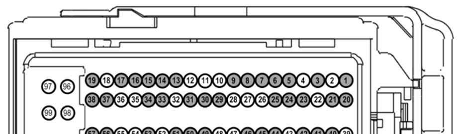
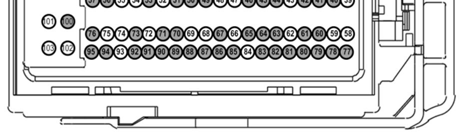
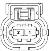

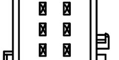
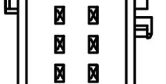
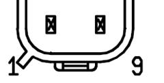
22 C100 C102A C1260 C1667 C1588 C1622 C1551B C146 C160A C160B Techline Page 22 of 22 IS
5.0L Controls Pack Insta llation Manual
 Please visit www.fordracingparts.com for the most current instruction and warranty information. PLEASE READ ALL OF THE FOLLOWING INSTRUCTIONS CAREFULLY PRIOR TO INSTALLATION. AT ANY TIME YOU DO NOT UNDERSTAND
Instruction Sheet 1 M T 2.3L Controls Pack
 Please visit https://performanceparts.ford.com for the most current instruction and warranty information. PLEASE READ ALL OF THE FOLLOWING INSTRUCTIONS CAREFULLY PRIOR TO INSTALLATION. AT ANY TIME YOU
5.0L Co ntrols Pack Installation Manual/Automatic
 Please visit www.performanceparts.ford performanceparts.ford.com.com for the most current instruction and warranty information. PLEASE READ ALL OF THE FOLLOWING INSTRUCTIONS CAREFULLY PRIOR TO INSTALLATION.
Controls Pack Installation Manual
 1 M-6017-A504VB Please visit www.performanceparts.ford.com for the most current instruction and warranty information.!!! PLEASE READ ALL OF THE FOLLOWING INSTRUCTIONS CAREFULLY PRIOR TO INSTALLATION. AT
Controls Pack Installation Manual L 4V
 Please visit www.performanceparts.ford.com for the most current instruction and warranty information.!!! PLEASE READ ALL OF THE FOLLOWING INSTRUCTIONS CAREFULLY PRIOR TO INSTALLATION. AT ANY TIME YOU DO
Controls Pack Installation Manual 2011 and newer 5.0L 4V and 5.4L 4V Engines
 Please visit www.fordracingparts.com for the most current instruction and warranty information.!!! PLEASE READ ALL OF THE FOLLOWING INSTRUCTIONS CAREFULLY PRIOR TO INSTALLATION. AT ANY TIME YOU DO NOT
Ford Racing 4.6L 3V Crate Engine Control Pack
 Ford Racing 4.6L 3V Crate Engine Control Pack Installation Time: 3-6 hours on a Foxbody Mustang Tools Required: Basic English and Metric Socket and Wrench Set Flat and Phillips Screwdrivers Torx bits Hammer
C FORD F250 / F L POWERSTROKE DIESEL WITH AUTOMATIC TRANSMISSIONS ONLY
 EXHAUST BRAKES C40019 1999-2003 FORD F250 / F350 7.3L POWERSTROKE DIESEL WITH AUTOMATIC TRANSMISSIONS ONLY Getting Started Thank you and congratulations on your purchase of a Pacbrake exhaust retarder.
PRXB EXHAUST BRAKE MAXIMUM EXHAUST FLOW DESIGN
 MAXIMUM EXHAUST FLOW DESIGN PRXB EXHAUST BRAKE C44072/C44073/C44074/C44075/C44076 APPLICATION: 994-2002 DODGE RAM TRUCKS W/5.9L CUMMINS DIESEL ENGINES WITH MANUAL & AUTOMATIC TRANSMISSIONS STOCK DODGE
C40008 & C40009 EXHAUST BRAKES
 EXHAUST BRAKES C40008 & C40009 1995 2003 Ford F250 / F350 7.3 L Powerstroke Diesel with manual transmissions 1995 1998 Ford F250 / F350 7.3 L Powerstroke Diesel with automatic transmission* *Requires the
HOLLEY VR2 FUEL PUMPS P/N & Installation Instructions 199R10975
 HOLLEY VR2 FUEL PUMPS P/N 12-3000 & 12-3000-2 Installation Instructions 199R10975 WARNING! THESE INSTRUCTIONS MUST BE READ AND FULLY UNDERSTOOD BEFORE BEGINNING INSTALLATION. FAILURE TO FOLLOW THESE INSTRUCTIONS
TOYOTA 4RUNNER COLD AIR INTAKE FJ CRUISER Preparation
 Preparation Part Number: PTR03-89100 Kit Contents Item # Quantity Reqd. Description 1 1 Air Filter (P/N: PTR43-00083) 2 1 Upper Air Box 3 1 Lower Air Box 4 1 Hump Coupler 5 1 Throttle Body Coupler 6 1
Mallory HyFire Electronic Ignition Control
 Mallory HyFire Electronic Ignition Control PN 690 Parts Included: 1 - Ignition 1 - Harness, Mag Pickup 1-18" Ground Wire 1-100V/1A Diode 4 - Mounting Screws WARNING: During installation, disconnect the
DFS Dynamic Fuel Systems Inc.
 DFS Dynamic Fuel Systems Inc. Dynami c Fuel System s Inc. Diesel Magnum US PAT# 7100582 Installation Manual Diesel Magnum US PAT# 7100582 Installation Manual Ver 52.1 www.dynamicfs.com www.fireemup.com
MUSTANG GT
 MAXFLOW FUEL PUMP BOOSTER Installation Instructions 2011-2012 MUSTANG GT P/N: 5A102-029 ENGINEERING, INC. 1650 Pacific Avenue, Channel Islands, CA 93033-9901 Phone 805 247-0226 Fax: 805 247-0669 www.vortechsuperchargers.com
Installation Instructions for Lingenfelter GM 2500 Suburban & Yukon XL Auxiliary Fan System (with AC clutch controlled fan output)
") Installation Instructions for Lingenfelter 2007-2013 GM 2500 Suburban & Yukon XL Auxiliary Fan System (with AC clutch controlled fan output) PN L300080607 Revision - 1.1 Lingenfelter Performance Engineering
Installation Instructions for Lingenfelter 2007-2013 GM 2500 Suburban & Yukon XL Auxiliary Fan System (with AC clutch controlled fan output) PN L300080607 Revision - 1.1 Lingenfelter Performance Engineering
DODGE SRT-4 PART NUMBER P (with Turbo Toys) P (without Turbo Toys) P (Stage 2 to Stage 3R Upgrade Kit)
 P (without Turbo Toys) P (Stage 2 to Stage 3R Upgrade Kit)") INFORMATION SHEET Stage 3R Turbo Upgrade Kit Components (1) Stage 3R PCM (4) 682 cc/min Fuel Injectors* (1) 3.0 bar MAP Sensor* (1) 3.0 bar TIP Sensor* (1) Block-off Connector for PCM (1) Mopar TD05HR
INFORMATION SHEET Stage 3R Turbo Upgrade Kit Components (1) Stage 3R PCM (4) 682 cc/min Fuel Injectors* (1) 3.0 bar MAP Sensor* (1) 3.0 bar TIP Sensor* (1) Block-off Connector for PCM (1) Mopar TD05HR
TELORVEK EFI 5.0 Coyote Sequential Fuel Injection System Part # CY-11
 Page #1 TELORVEK EFI 5.0 Coyote Sequential Fuel Injection System Part # CY-11 WIRING INSTRUCTIONS Thank you for purchasing the absolute finest of wiring kits for the Ford Motor Co. Coyote modular engine.
MODEL NUMBER: MEDIUM DUTY ONBOARD AIR SYSTEM
 MODEL NUMBER: 10003 MEDIUM DUTY ONBOARD AIR SYSTEM IMPORTANT: It is essential that you and any other operator of this product read and understand the contents of this manual before installing and using
PIMP Ford 5.0 Harness Installation Manual. Part Number: PM-75
 PIMP Ford 5.0 Harness Installation Manual Part Number: PM-75 Ron Francis Wiring 200 Keystone Rd Suite 1 Chester, PA 19013 800-292-1940 www.ronfrancis.com Pre-Installation Notes: This system is designed
WOT Box Installation Instructions VW / Audi
 Connector Pinout Pin Color AWG Name WOT Box Installation Instructions VW / Audi Description 1 Yellow 18 RPM Connect to Fuel Injector Drive Signal or Ignition Control Signal (varies by car model) 2 Black
INSTALLATION INSTRUCTIONS
 OEM Recessed Lip Camera with Harness and Slimline Mirror (Kit part number 9002-8724) Please read thoroughly before starting installation and check that kit contents are complete. Items Included in the
2010 FORD TRANSIT ELECTRONIC CRUISE KIT Part Number:
 General Applicability Recommended Tools Item # Qty. Description 1. 250-2758 1 Cruise Control Module 2. 250-2760 1 Switch Harness 3. 250-2759 1 Main Wiring Harness 4. 250-2771 1 Pedal Interface Harness
OFF-ROAD ELECTRONIC IGNITION CONTROL
 INSTALLATION INSTRUCTIONS FORM 1678M 05/07 OFF-ROAD ELECTRONIC IGNITION CONTROL GENERAL INFORMATION This ignition includes a single stage RPM limiter. You can set various settings using the switches that
Generation III Stand Alone Engine Harness
 78 Rattler Curry Road, Columbia, KY 42728 Phone 1-888-467-4491 sales@bp-automotive.com www.bp-automotive.com Generation III Stand Alone Engine Harness Installation Guide At BP Automotive we take pride
SUM EFI Wiring Harness for GM LS1 Engine INSTALLATION INSTRUCTIONS
 SUM-890122 EFI Wiring Harness for GM LS1 Engine INSTALLATION INSTRUCTIONS 1 INTRODUCTION This harness is designed for GM 1997-2002 LS1 fuel injected engines utilizing a mechanical throttle body and throttle
PRXB EXHAUST BRAKE HIGH PERFORMANCE
 HIGH PERFORMANCE PRXB EXHAUST BRAKE C44059, C4406, C44063, C44065 APPLICATION 994-2002 DODGE RAM AUTOMATIC TRUCKS EQUIPPED WITH 47RE TRANSMISSIONS WITH 5.9L, 24 VALVE CUMMINS DIESEL ENGINES GETTING STARTED
V8 Gen. V Ford Mustang 2010 Update
 V8 Gen. V Ford Mustang 2010 Update There were several updates to the Ford Mustang in the 2010 model year. This document outlines the differences between the installation steps necessary for the 2010 Mustang
Controls Pack Installation Manual L 4V
 Please visit www.fordperformanceracingparts.com for the most current instruction and warranty information.!!! PLEASE READ ALL OF THE FOLLOWING INSTRUCTIONS CAREFULLY PRIOR TO INSTALLATION. AT ANY TIME
HP FUEL PUMPS P/N & Installation Instructions 199R10569
 HP FUEL PUMPS P/N 12-700 & 12-890 Installation Instructions 199R10569 WARNING! THESE INSTRUCTIONS MUST BE READ AND FULLY UNDERSTOOD BEFORE BEGINNING INSTALLATION. FAILURE TO FOLLOW THESE INSTRUCTIONS MAY
EVAP system, servicing
 Page 1 of 65 20-130 EVAP system, servicing EVAP system components 1 - Cap nut 10 Nm 2 - Cover 3 - Stud For EVAP canister 15 Nm 4 - Sealing piece 5 - Bleed line To EVAP canister purge regulator valve -
DOMINATOR FUEL PUMPS P/N & Installation Instructions 199R10573
 DOMINATOR FUEL PUMPS P/N 12-1400 & 12-1800 Installation Instructions 199R10573 WARNING! THESE INSTRUCTIONS MUST BE READ AND FULLY UNDERSTOOD BEFORE BEGINNING INSTALLATION. FAILURE TO FOLLOW THESE INSTRUCTIONS
Operating and Installation Instructions
 Model Number 40401-c (-sp) Electronic Fuel Pump Operating and Installation Instructions This Product is Patent Pending. Application available upon request CAUTION! This product is to be installed only
Fuel System Diagnosis
 Page 1 of 6 2001 Chevrolet Express Express, Savana (VIN G) Service Manual Engine Engine Controls - 5.0L and 5.7L Diagnostic Information and Procedures Document ID: 720867 Fuel System Diagnosis Circuit
HP FUEL PUMPS P/N ERL & ERL Installation Instructions 199R11108
 HP FUEL PUMPS P/N 1200600ERL & 1200890ERL Installation Instructions 199R11108 WARNING! THESE INSTRUCTIONS MUST BE READ AND FULLY UNDERSTOOD BEFORE BEGINNING INSTALLATION. FAILURE TO FOLLOW THESE INSTRUCTIONS
G - TESTS W/CODES - 2.2L
 G - TESTS W/CODES - 2.2L 1994 Toyota Celica 1994 ENGINE PERFORMANCE Toyota 2.2L Self-Diagnostics Celica INTRODUCTION If no faults were found while performing F - BASIC TESTING, proceed with self-diagnostics.
HEAVY DUTY ONBOARD AIR SYSTEM
 HEAVY DUTY ONBOARD AIR SYSTEM PART NO. 10005 IMPORTANT: It is essential that you and any other operator of this product read and understand the contents of this manual before installing and using this
Installation Instructions General Motors 8.1 Sequential Vapor Injection (S.V.I.) System 7500/6500 Series Trucks model year.
 System 7500/6500 Series Trucks model year.") Installation Instructions General Motors 8.1 Sequential Vapor Injection (S.V.I.) System 7500/6500 Series Trucks 2003-2005 model year. Technocarb Equipment (2004) Ltd. 4-30435 Progressive Way Abbotsford,
Installation Instructions General Motors 8.1 Sequential Vapor Injection (S.V.I.) System 7500/6500 Series Trucks 2003-2005 model year. Technocarb Equipment (2004) Ltd. 4-30435 Progressive Way Abbotsford,
M-9424-M50CJ INTAKE MANIFOLD INSTALLATION INSTRUCTIONS
 Please visit www.fordracingparts.com for the most current instruction information!!! PLEASE READ ALL OF THE FOLLOWING INSTRUCTIONS CAREFULLY PRIOR TO INSTALLATION. AT ANY TIME YOU DO NOT UNDERSTAND THE
NUMBER: GROUP: DATE: November 12, 2005 SUBJECT: OVERVIEW: MODELS: SYMPTOM/CONDITION: REV A. Electrical
 NUMBER: GROUP: 08-036-05 REV A Electrical DATE: November 12, 2005 This bulletin is supplied as technical information only and is not an authorization for repair. No part of this publication may be reproduced,
Installation and Operation Guide. Tundra HD 2500 Power Inverter. for the. Webasto BlueCool Truck System
 Installation and Operation Guide Tundra HD 2500 Power Inverter for the Webasto BlueCool Truck System www.tundrainternational.com www.techwebasto.com BCTSP0063A Table of Contents 1. Introduction 4 1.1 Disclaimer.................................................................................
2002 Buick Rendezvous - AWD
 2002 Buick Rendezvous - AWD DTC P0410 Description The control module activates the secondary air injection (AIR) system by grounding both the pump relay and the vacuum control solenoid control circuits.
INSTALLATION INSTRUCTIONS
 OEM Recessed Lip Camera with Harness and Auto Dimming Mirror (Kit part number 9002-8721) Please read thoroughly before starting installation and check that kit contents are complete. Items Included in
MALLORY FIRESTORM CD MULTI COIL HARDWARE INSTALLATION - PN 69050S / 69050R
 FORM 69050S/R MALLORY FIRESTORM CD MULTI COIL HARDWARE INSTALLATION - PN 69050S / 69050R To ensure you are using the most current instruction sheet, please visit www.malloryfirestorm.com. CAUTION! The
HYFIRE 6AL2 ELECTRONIC IGNITION CONTROL
 INSTALLATION INSTRUCTIONS FORM 1643 HYFIRE 6AL2 ELECTRONIC IGNITION CONTROL PART NO 6861M PARTS INCLUDED: 1 HYFIRE 6AL2 Ignition Control 4 #10 Sheet Metal Screws 2 Wire Ties 2 Ring Terminals, Insulated
Part Number:
 General Applicability This cruise control was tested and verified on: 2009-2010 Ford F-150 / E-150 2010 Ford Escape 2009-2010 Mazda Tribute This cruise control may not function correctly on unverified
1998 ENGINE PERFORMANCE. General Motors Corp. - Basic Diagnostic Procedures - 5.7L
 INTRODUCTION 1998 ENGINE PERFORMANCE General Motors Corp. - Basic Diagnostic Procedures - 5.7L The following diagnostic steps will help prevent overlooking a simple problem. This is also where to begin
SUM EFI Wiring Harness for GM LT-1/LT-4 Engine INSTALLATION INSTRUCTIONS
 SUM-890121 EFI Wiring Harness for GM LT-1/LT-4 Engine INSTALLATION INSTRUCTIONS INTRODUCTION This harness is designed for GM 1992-97 LT1/LT4 fuel injected engines. Even with minimal electrical experience,
Powertrain DTC Summaries EOBD
 Powertrain DTC Summaries Quick Reference Diagnostic Guide Jaguar X-TYPE 2.0 L 2002.25 Model Year Refer to page 2 for important information regarding the use of Powertrain DTC Summaries. Jaguar X-TYPE 2.0
Part Number: TDZ-75SD / BRONCO-75SD
 Ford 5.0 EFI Harness Installation Manual For Classic Fords & Mustangs and Early Broncos Part Number: TDZ-75SD / BRONCO-75SD Ron Francis Wiring & The Detail Zone 200 Keystone Rd. Chester, PA 19013 800-292-1940
MALLORY FIRESTORM CD MULTI COIL HARDWARE INSTALLATION - PN 69150C / 69150R
 FORM 69150C/R MALLORY FIRESTORM CD MULTI COIL HARDWARE INSTALLATION - PN 69150C / 69150R To ensure you are using the most current instruction sheet, please visit www.malloryfirestorm.com. CAUTION! The
SVE BULLETIN and later Transit Stationary Elevated Idle Control
 Q-239 2016 and later Transit Stationary Elevated Idle Control Models Affected All 2016 and later Model Year Transit Vans, Wagons, Cutaways, and Chassis Cab Vehicles. Purpose To explain changes and functions
Installation Instructions
 Installation Instructions for 15912 to 15916 Electric Fuel Pumps & Fuel Pressure Regulators Installation Instructions WARNING! These instructions must be read and fully understood before beginning the
Getting Started. INLINE MOUNT Exhaust Brakes. Thank you and congratulations on your purchase of a Pacbrake Inline Mount exhaust brake kit.
 Getting Started Thank you and congratulations on your purchase of a Pacbrake Inline Mount exhaust brake kit. Before starting, be sure you have attained the proper brake, mounting kit and control group
STARTING SYSTEMS 8B - 1 STARTING SYSTEMS CONTENTS
 TJ STARTING SYSTEMS 8B - 1 STARTING SYSTEMS CONTENTS page DESCRIPTION AND OPERATION STARTER MOTOR... 2 STARTER RELAY... 3 STARTING SYSTEM... 1 DIAGNOSIS AND TESTING STARTER MOTOR... 8 STARTER MOTOR NOISE
Installation Instructions for Lingenfelter GM 2500 Suburban & Yukon XL Auxiliary Fan System (with ECM controlled fan output)
") Installation Instructions for Lingenfelter 2007-2013 GM 2500 Suburban & Yukon XL Auxiliary Fan System (with ECM controlled fan output) PN L300090607 Revision - 1.1 Lingenfelter Performance Engineering
Installation Instructions for Lingenfelter 2007-2013 GM 2500 Suburban & Yukon XL Auxiliary Fan System (with ECM controlled fan output) PN L300090607 Revision - 1.1 Lingenfelter Performance Engineering
IT IS IMPORTANT THAT YOU OBTAIN THE CORRECT INFORMATION FOR YOUR VEHICLE, OR DAMAGE TO THE WIRING SYSTEM COULD OCCUR.
 Instructions for Universal Harness PRINT THESE INSTUCTIONS Gentex Mirror Installation Instructions Provided by www.rearviewautomirrors.com These instructions have been prepared to provide you with details
3 in 1 TRAIL CHARGER with LOCKOUT
 Owner s Manual P/N: 283821 500 3 in 1 TRAIL CHARGER with LOCKOUT 283821 01 Version 2.04 07/05/2011 Owners Manual Operation Installation Wiring Diagram Troubleshooting Parts Breakdown 1 GENERAL OPERATION
Zoom and Print Options
 Vehicle» Engine, Cooling and Exhaust» Engine» Service and Repair» Removal and Replacement» Engine Replacement Engine Replacement ^ Tools Required - J 38185 Hose Clamp Pliers Removal Procedure 1. Remove
TOYOTA FJ CRUISER / 4RUNNER COLD AIR INTAKE Section I Installation Preparation. 4.0L V6 (1GR) Roller Rocker Part Number(s): PTR
 Roller Rocker Part Number(s): PTR") Section I Installation Preparation Part Number(s): PTR03-89100 Kit Contents Item # Quantity Reqd. Description 1 1 Air Filter (P/N: PTR43-00083) 2 1 Upper Air Box 3 1 Lower Air Box 4 1 Hump Coupler 5 1
Section I Installation Preparation Part Number(s): PTR03-89100 Kit Contents Item # Quantity Reqd. Description 1 1 Air Filter (P/N: PTR43-00083) 2 1 Upper Air Box 3 1 Lower Air Box 4 1 Hump Coupler 5 1
Modifying a 5.0 Mustang MAF EFI Harness for Standalone Operation in Another Vehicle
 Modifying a 5.0 Mustang MAF EFI Harness for Standalone Operation in Another Vehicle Starting Point: A used harness can be sourced from any 5.0 equipped Mustang with Mass Air Flow (MAF). MAF was first introduced
DTC P0172 Fuel Trim System Rich
 Page 1 of 6 1997 Chevrolet Cavalier Cavalier, Sunfire (VIN J) Service Manual Document ID: 47788 DTC P0172 Fuel Trim System Rich System Description A Closed Loop air/fuel metering system is used to provide
 Page 1 of 9 Home Account Contact ALLDATA Log Out Help DAN GRIMWOOD DAN GRIMWOOD00002 Select Vehicle New TSBs Technician's Reference Component Search: OK 1985 Dodge Truck D 350 Pickup V8-360 5.9L VIN I
Not required for most applications. Not required for most applications. High pressure ( provided) High pressure ( provided)
 High pressure ( provided)") ELECTRIC FUEL PUMPS P/N 12-801-1, 712-801-1, 12-802-1, 12-802-2, 712-802-1, 12-812, 12-815-1, & 712-815-1 FUEL PRESSURE REGULATORS P/N 12-500, 12-501, 12-803, 12-803BP, 12-804, & 15812NOS Installation
ELECTRIC FUEL PUMPS P/N 12-801-1, 712-801-1, 12-802-1, 12-802-2, 712-802-1, 12-812, 12-815-1, & 712-815-1 FUEL PRESSURE REGULATORS P/N 12-500, 12-501, 12-803, 12-803BP, 12-804, & 15812NOS Installation
MY F150 SuperCab 1. Tools Required. Page 1 of 12 9L3J-19A014-BA Copyright Ford 2013 FoMoCo
 2009-2014MY F150 SuperCab 1 Tools Required A B C D E F G 3X 6X 3X H I J 2X 3X 3X K L M N 3X Page 1 of 12 9L3J-19A014-BA Copyright Ford 2013 FoMoCo 2009-2014MY F150 SuperCab 2 Subwoofer Power Wire Routing
INSTALLATION INSTRUCTIONS. Revision 3.1.1
 INSTALLATION INSTRUCTIONS Revision 3.1.1 Table of Contents INTRODUCTION... 4 INSTALLATION OVERVIEW... 5 Included Parts... 6 DEVICE WIRING... 7 Required Parts... 7 Guidelines... 7 Wiring Diagram... 8 Compatible
Ford 7.3L Powerstroke
 29 December 2015 P/N# 1027144 Ford 7.3L Exhaust Brake (I-00368) 1 1999-2003 Ford 7.3L Powerstroke Remote Mount BD Exhaust Brake P/N 1027144 Application Ford 7.3L Air Exhaust Brake 99-03 4.0 Exhaust Serial
MEDIUM DUTY ONBOARD AIR SYSTEM
 MEDIUM DUTY ONBOARD AIR SYSTEM PART NO. 10003 IMPORTANT: It is essential that you and any other operator of this product read and understand the contents of this manual before installing and using this
TIP SHEET. Installation Tips for your RS IB-MUX / PKUMUX (D) + SPDT T1205 v1.2 4/3/14. 1 P a g e
 + SPDT T1205 v1.2 4/3/14. 1 P a g e") Installation Tips for your RS-150 + IB-MUX / PKUMUX (D) + SPDT T1205 v1.2 4/3/14 TIP SHEET Thank you for purchasing your remote start from MyPushcart.com - an industry leader in providing remote starts
Installation Tips for your RS-150 + IB-MUX / PKUMUX (D) + SPDT T1205 v1.2 4/3/14 TIP SHEET Thank you for purchasing your remote start from MyPushcart.com - an industry leader in providing remote starts
Before installing your Roush Performance Product(s), read through the entire installation procedure and check to make sure all items are present.
, read through the entire installation procedure and check to make sure all items are present.") Ford Mustang Roush Fog Lamp Wiring Harness Installation Instructions Application: 2005 Ford Mustang GT Model (Designed for use with Roush Fog Lamps SM01-6400-AL) Before installing your Roush Performance
Ford Mustang Roush Fog Lamp Wiring Harness Installation Instructions Application: 2005 Ford Mustang GT Model (Designed for use with Roush Fog Lamps SM01-6400-AL) Before installing your Roush Performance
V1 Truck Manifold Turbo Kit for F-body
 V1 Truck Manifold Turbo Kit for 98-02 F-body Prep: -Remove all A/C Components, Alternator and brackets, tensioner, front bumper, front bumper foam, and front bumper support. Remove radiator and cooling
Ford 6.7L Powerstroke Positive Air Shutoff
 8 April 2013 Ford 6.7L 2011-2012 Positive Air Shutoff 1 2011-2012 Ford 6.7L Powerstroke Positive Air Shutoff P/N# 1036703 P/N# 1036703-M UPLEASE READ ALL INSTRUCTIONS BEFORE INSTALLATION BD Engine Brake
owners manual Banks Brake with installation instructions Exhaust BrakE system Dodge IsB 5.9L Cummins (24-valve) turbo-diesel Pickups
 turbo-diesel Pickups") owners manual with installation instructions Banks Brake Exhaust BrakE system 1998-2002 Dodge IsB 5.9L Cummins (24-valve) turbo-diesel Pickups THIS MANUAL IS FOR USE WITH SYSTEM 55219 & 55221 2010 gale
owners manual with installation instructions Banks Brake Exhaust BrakE system 1998-2002 Dodge IsB 5.9L Cummins (24-valve) turbo-diesel Pickups THIS MANUAL IS FOR USE WITH SYSTEM 55219 & 55221 2010 gale
CSI-400 Installation Instructions
 CSI-400 Installation Instructions Kit Contents Installation Precautions: Roll down window to avoid locking keys in vehicle during installation Avoid mounting components or routing wires near hot surfaces
INSTALLATION INSTRUCTIONS
 INSTALLATION INSTRUCTIONS 2009 CORVETTE LS - 9 INSTALLATION INSTRUCTIONS FOR LS 9 The following instructions are intended as an aid to assist in harness installation. More in depth information can be obtained
Dodge Cummins Positive Air Shutoff
 1 INSTALL MANUAL 2010-2012 6.7 Dodge Cummins Positive Air Shutoff P/N# 1036722 P/N# 1036722-M UPLEASE READ ALL INSTRUCTIONS BEFORE INSTALLATION An Information decal has been provided in this kit. This
Rostra Electronic Cruise Control Install On a Stratoliner or Roadliner
 Rostra Electronic Cruise Control Install On a Stratoliner or Roadliner MATERIALS LIST: 1 - Rostra Part # 250-1223 (www.brandondist.com/products/cruise1223.htm) 1 - Signal Splitter part # 250-4369 1 - Engagement
Water in Fuel Sensor Kit
 03/08/2016 1050355-1050356 Water in Fuel Sensor Kit (I-00369) 1 Water in Fuel Sensor Kit Fast and Accurate Detection of Water in Diesel Fuel 1050355 Universal Kit For use with BD FlowMax water separator
Powertrain DTC Summaries OBD II
 Powertrain DTC Summaries Quick Reference Diagnostic Guide Jaguar X-TYPE 2.5L and 3.0L 2002 Model Year Revised January, 2002: P0706, P0731, P0732, P0733, P0734, P0735, P0740, P1780 POSSIBLE CAUSES Revised
MY F150 CrewCab 1. Tools Required E F G. Page 1 of 10 9L3J-19A014-AA Copyright Ford 2013 FoMoCo
 2009-2014MY F150 CrewCab 1 Tools Required A B C D 3X E F G H 2X I 6X 3X Page 1 of 10 9L3J-19A014-AA Copyright Ford 2013 FoMoCo 2009-2014MY F150 CrewCab 2 Subwoofer Power Wire Routing All Vehicles WARNING:
jegs.com
 Contents Wiring Harness w/ Fuse Panel Installation Instructions Turn Signal Plug w/ Terminals 2 Headlight Plugs 3/4 Grommet 10 ¼ Terminals 4 Ring Terminals 10 Wire Ties Fusible Link 2 Screws & Nuts 2 Plastic
HEAVY DUTY ONBOARD AIR SYSTEM PART NO
 IMPORTANT: It is essential that you and any other operator of this product read and understand the contents of this manual before installing and using this product. SAVE THIS MANUAL FOR FUTURE REFERENCE
Condition. Correction
 #06-06-04-008B: LNJ Service Engine Soon (SES) Light On, Multiple Powertrain Control Module (PCM) Diagnostic Trouble Code (DTC) P1404 and/or P0404 (Install EGR Valve/Gasket/Pipe/Wiring Harness Connector,Reprogram
TIP SHEET T0937. Installation Tips For RS00/PS00 + ADS-TBSL-PL + SPDT
 Installation Tips For RS00/PS00 + ADS-TBSL-PL + SPDT TIP SHEET T0937 Thank you for purchasing your remote start from MyPushcart.com - an industry leader in providing remote starts to do-it-yourself installers
Jacobs Exhaust Brake. Installation Manual. For 2003 through 2006 Dodge Ram Trucks Equipped with the Cummins ISB 5.9 Engine
 Jacobs Exhaust Brake For 2003 through 2006 Dodge Ram Trucks Equipped with the Cummins ISB 5.9 Engine Installation Manual Please see Web Site for latest instructions www.jakebrake.com CUMMINS E BRAKE BY
CLASSIC UPDATE WIRING KIT
 by Randy Irwin 1955-57 CLASSIC UPDATE WIRING KIT Randy Irwin - Technical Writer Randy has been involved in the Chevy parts business for over 25 years. He is a wizard at creating, making and modifying custom
On all settings above 100 horsepower the following precautions should be observed:
 ELECTRONIC FUEL INJECTED 5.0 COYOTE PLATE SYSTEM INSTALLATION INSTRUCTIONS Congratulations on the purchase of your Nitrous Express Coyote Plate system. Nitrous Express utilizes only the highest quality
Installation Tips for your Remote Start system (for RS4LX>GMBP for GM vehicles)
") Installation Tips for your Remote Start system (for RS4LX>GMBP for GM vehicles) Thank you for purchasing your remote start from MyPushcart.com - an industry leader in providing remote starts to doit-yourself
Installation Tips for your Remote Start system (for RS4LX>GMBP for GM vehicles) Thank you for purchasing your remote start from MyPushcart.com - an industry leader in providing remote starts to doit-yourself
MSD-8 Plus Ignition PN 7805
 MSD-8 Plus Ignition PN 7805 Note: Solid Core spark plug wires cannot be used with an MSD Ignition. Parts Included: 1 - MSD-8 Plus Ignition 1 - Mag Pickup Extension Harness, PN 8860 4 - Vibration Mounts
EMISSION CONTROL SYSTEM
 XJ EMISSION CONTROL SYSTEM 25-1 EMISSION CONTROL SYSTEM TABLE OF CONTENTS ON-BOARD DIAGNOSTICS 2.5L DIESEL ENGINE... 1 EXHAUST EMISSION CONTROLS 2.5L DIESEL ENGINE... 6 ON-BOARD DIAGNOSTICS 2.5L DIESEL
SPEED CONTROL 4 AND 6 CYL. JEEP WRANGLER. Read entire instructions thoroughly before starting. INSTALLATION INSTRUCTIONS TOOLS REQUIRED:
 Read entire instructions thoroughly before starting. TOOLS REQUIRED: SPEED CONTROL 4 AND 6 CYL. JEEP WRANGLER INSTALLATION INSTRUCTIONS Complete socket set Phillips screwdriver Torx drivers Wire strippers/cutters
Audi A4 Current Flow Diagram No. 44 / 1 Edition
 Page 1 of 16 Audi A4 Current Flow Diagram No. 44 / 1 Edition 05.2003 1.8 l - Fuel injection engine (110 kw - Motronic - 4 cylinder), engine code AVJ from model year 2002 1.8 l - Fuel injection engine (120
Remove black panel shown. Save 6 retaining pins for re-install later. Pry up on center part of pin first. Then pry out entire retaining pin.
 2005-2009 Ford Mustang V6 Fog Light Wiring Kit Parts List: Quantity: Tools Required: Wiring harness 1 Flat head screwdriver Supplemental wire leads 2 Ratchet & Socket set OR Wire tap red 2 Adjustable Wrench
Duramax Lift Pump Kit 9-11 PSI Installation Instructions P/N# D
 2001-10 Duramax Lift Pump Kit 9-11 PSI Installation Instructions P/N# 1050320D PLEASE READ ALL INSTRUCTIONS CAREULLY BEORE INSTALLATION Kit Contents 1500365-P2 1500330-D lowmax Lift Pump V3 lowmax Wiring
M-9603-CJ 123 mm Cold Air Kit for 5.4L 4V V8 Cobra Jet Mustang INSTALLATION INSTRUCTIONS
 Please contact the Techline for the most current instruction information 1-800-367-3788.!!! PLEASE READ THE FOLLOWING INSTRUCTIONS CAREFULLY PRIOR TO INSTALLATION!!! OVERVIEW: This kit is designed for
ISIS Power Manual and Installation Guide Race Car Replicas- Superlite Coupe
 ISIS Power Manual and Installation Guide Race Car Replicas- Superlite Coupe Table of Contents Overview... 2 System Details... 3 Kit Includes... 3 Technical Specifications... 3 Harness Descriptions... 4
Aftermarket Interface Module
 An ISO 9001:2008 Registered Company Aftermarket Interface Module (2015-2018 Ford Transit) AIM514-B High Side Solenoid type Coolant Valve Control AIM515-B Motor Reversing type Coolant Valve Control Introduction
Ford 6.0L Powerstroke
 10 March 2017 P/N#1027145 / 1027146 / AP Ford 6.0L Exhaust Brake (I-00084) 1 DOWNLOAD ENHANCED INSTALL MANUALS AT dieselperformance.com 2003-2007 Ford 6.0L Powerstroke Remote Mount BD Exhaust Brake BD
KIT CONTENTS. Multimeter or test light Wire crimpers or soldering equipment. Wire terminals & connectors 10A inline fuse
 RUSSELL FORD 5.0L COMPLETE EFI PLUMBING KIT INSTALLATION INSTRUCTIONS Please study these instructions carefully before installing your new complete fuel system kit. If you have any questions, please call
Gentex Homelink Installation Instructions
 Gentex Homelink Installation Instructions Kit Contents: Item Qty Part Description 1 Number GENK-41 NVS Homelink Mirror GENK-42 NVS Homelink w/mood lights 1 of the GENK-45 NVS Homelink w/compass following