Controls Pack Installation Manual 2011 and newer 5.0L 4V and 5.4L 4V Engines
|
|
|
- Allan Floyd
- 6 years ago
- Views:
Transcription

1 Please visit for the most current instruction and warranty information.!!! PLEASE READ ALL OF THE FOLLOWING INSTRUCTIONS CAREFULLY PRIOR TO INSTALLATION. AT ANY TIME YOU DO NOT UNDERSTAND THE INSTRUCTIONS, PLEASE CALL THE FORD RACING TECHLINE AT !!! Controls Pack Installation Manual 2011 and newer 5.0L 4V and 5.4L 4V Engines Techline Page 1 of 16 IS
2 TABLE OF CONTENTS Section Topic Page 1.0 Introduction Overview Included Components Tools Required Pre-Installation of Harness and Parts Harness Wire Colors and Connector Locations Harness Installation Blunt Lead Wiring Connections Fuel System PDB Installation Initial Start Up PCM Connector Face and Usage Charts INTRODUCTION This kit was developed by Ford Racing to allow performance enthusiasts to easily install todayʼs modern muscle into street rods from yesterday. We have developed this system to take the complexity and mystery out of installing a Mustang Electronic Throttle Control (ETC) engine into your vehicle. Important Note for 5.4L Crate Engine Applications: The FR wiring harness in this kit must interface to a production engine harness for model years 2011 and newer. The FR wiring harness will not interface to a 5.4L engine harness for model years. If you own one of these harnesses, you must purchase a 5.4L engine harness for a 2011 Mustang. For 5.0L engine applications a 2011 Mustang GT manual transmission engine harness must be used. This engine controls pack is designed for manual transmission applications or automatics with a stand alone controller. Techline Page 2 of 16 IS
 367-3788. 3.0 COMPONENTS INCLUDED 3.")

3 2.0 OVERVIEW This booklet provides a step by step guide for the preparation and installation of the controls pack. Please read the instructions thoroughly before starting the installation. If you have any questions, contact Ford Racing Technical Support at (800) COMPONENTS INCLUDED 3.1 Cowl Wiring Harness CM-14A006-A5LA This harness is labeled and includes all connections required to power up and run your engine equipped with a 2011 or newer factory engine harness. 3.2 Ford Racing Power Distribution Box CM-14A068-A The FRPDB connects directly to the CM-14A006-A5LA wiring harness. The FRPDB contains all relays and fuses needed for engine, air conditioner, intercooler pump (5.4L Only), and cooling fan control. The FRPDB may be mounted either in the passenger compartment (preferred) or in underhood locations away from direct sources of heat such as exhaust headers. Techline Page 3 of 16 IS
 CM-12A650-A5LA (5.0L 4V) CM-12A650-A54LA (5.")
 and Return Style fuel system as shown on page 12.")

4 3.3 Accelerator Pedal BR3Z-9F836-D This pedal is required for correct electrical interface with the PCM. The engine will not operate correctly without this exact pedal. 3.4 Powertrain Control Module (PCM) CM-12A650-A5LA (5.0L 4V) CM-12A650-A54LA (5.4L 4V Supercharged) Commonly referred to as the engine computer, or brain, this PCM is calibrated for operation with a non-modified air box/bucket and air inlet tube (included in kit) and Return Style fuel system as shown on page 12. The PCM is designed for underhood mounting but may also be located in the wet cowl/wiper motor area or passenger compartment of the vehicle if desired. Wiring modifications may be required to support location of the PCM in either of these two areas. The pictures below show an example of the PCM installed in the wet cowl area. Techline Page 4 of 16 IS

5 This PCM will NOT work with a Returnless style fuel system as used on factory Mustang vehicles. Should only be used with Premium Fuel. NOTE: Due to the fuel system requirement described above, installation of this PCM in ANY Production Mustang vehicle will result in a no-start condition! 3.5 UEGO Sensor 8F9A-9Y460-EA Two Universal Heated Exhaust Gas Oxygen sensors provide wide range feedback to the PCM for closed loop air fuel ratio control. * Apply a light coat of anti-seize lubricant to the threads of the HO2S before installing. Tighten to 48 Nm (35 lb-ft). Techline Page 5 of 16 IS
6 4.0 TOOLS REQUIRED In addition to a common assortment of sockets, wrenches and screwdrivers, you will also need the following: Wire Strippers Digital Volt/Ohm Meter Solder Gun / Solder Electrical Tape / Shrink Tubing Hand Drill Hole Saw Utility Knife 5.0 PRE-INSTALLATION 5.1 Disconnect the battery prior to performing any wiring modifications. 5.2 Identify mounting location for the PCM and FRPDB. The harness design in this kit assumes PCM location in the right front (passenger side) of the engine compartment and FRPDB installation in the glove box/passenger compartment area. Some customers have successfully located both the PCM and FRPDB in the passenger compartment glove box area some minor wiring modifications may be required to accommodate this configuration. Either location is acceptable as long as all connectors are able to mate without excessive strain on the harness wiring. 5.3 Identify where the Ford Racing Controls Pack harness can pass through on the Right (Passenger) side of the bulkhead. You will need to determine the proper location to cut a hole for the harness to pass through. Check for any wires, hoses, etc. that may become damaged by the hole saw. 5.4 Use a center punch to mark the location of the center of the hole. By using the center punch, this will keep the drill bit from ʻwalkingʼ while you are cutting through the bulkhead. 5.5 Drill hole to size required to allow OBD II and accelerator pedal connectors to pass through from engine to passenger compartment. Clean any sharp edges with a file or die grinder. 5.6 The grommet will need to be cut in order to be installed onto the harness. Using a utility knife, carefully make one cut starting from the inside of the grommet and cutting outwards. It is always safest to pull the knife away from you while cutting. 5.7 Route the harness through the hole, starting from the engine compartment side; pass the accelerator pedal connector (Page 8, Connector #4), OBD II connector (Page 8, Connector #5), and blunt leads into the passenger compartment. 5.8 Route the accelerator pedal connector, OBD II connector, and blunt leads under the dashboard and towards the driver (left) side of the vehicle. 5.9 Route the remaining Fuel Pump Lead (Green wire) along the passenger side floor boards to the fuel pump at the rear of the vehicle Install the PCM and FRPDB. Techline Page 6 of 16 IS
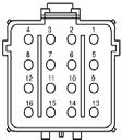
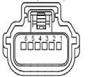
7 6.0 HARNESS WIRE COLORS AND CONNECTOR LOCATIONS BK = Black GY = Gray PK = Pink WH = White BR = Brown LB = Light Blue VT = Violet YE= Yellow DB = Dark Blue LG = Light Green RD = Red DG = Dark Green OG = Orange TN = Tan Number Connector Connects to Wire colors/pin locations 1 Blunt lead wire connections See page 11 See Page 15 2 UEGO L Bank 2 Universal Exhaust Gas Oxygen See Page 15 3 UEGO R Bank 1 Universal Exhaust Gas Oxygen See Page 15 4 Accelerator Pedal Accelerator Pedal Assembly (APPS) See Page 15 5 OBD II Diagnostic connection Diagnostic equipment See Page 15 6 EPAS (AIM for race car) Electronic Power Assisted Steering (if equipped) See Page 14 7 PDB (15 pin) Power Distribution Box See Page 16 8 PDB BEC Power Distribution Box (bolt in) See Page 16 9 Intercooler pump Supercharger Intercooler Pump See Page MAF Mass Airflow Sensor See Page ALT Alternator See Page Chassis ground eyelet Vehicle frame / Sub-frame Black 13 Cooling fan Cooling fan motor Orange=pos. Black=neg. 14 PCM (50 way) Powertrain Control Module See Page PCM (70 way) Powertrain Control Module See Page In-Line Connector (ILC) Engine harness See Page Starter solenoid, Battery NEG Starter Solenoid / Batt. NEG post Starter=white Batt.neg.=Black Techline Page 7 of 16 IS
8 Techline Page 8 of 16 IS
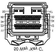
9 Techline Page 9 of 16 IS
10 7.0 HARNESS INSTALLATION 7.1 Attach main engine harness connector (Page 8, Connector #8) to the PDB. Use a Phillips screwdriver to gently snug the mounting screw for this connector. Access to this screw is through a hole in the back side of PDB. 7.2 Attach the PCM Connector (Page 9, Connector #15) to the cowl pocket (outside 70 pin connector) of the PCM 7.3 Attach the Auxiliary Inline Connector (Page 9, Connector #16) to the mating Inline Connector of a 2011 MY or newer engine harness. 7.4 Attach the 15 pin FRPDB Connector (Page 8, Connector #7) to the FRPDB. Leave the lid off of the FRPDB until verification of installation is complete to allow for trouble-shooting if necessary. 7.5 Using a sheet metal screw, attach the eyelet (Page 9, Connector #12) to the inner fender or bulkhead. Verify that you have a good reliable ground path from the battery negative post to the location being used for this eyelet on the chassis. In general, the resistance from the battery ground to this chassis location should be less than 0.1 ohm. 7.6 (5.4L Only) Route the supercharger Intercooler Pump Connector (Page 9, Connector #9) down toward the bottom of the radiator, and find a suitable location to mount the intercooler pump that will still reach this connector. After mounting the intercooler pump, attach the connector. 7.7 Find a mounting location for the Accelerator Pedal. Ensure that the mounting location is sufficiently strong so the mounting surface will not fatigue over time from the constant usage of the accelerator pedal. If necessary, fabricate an additional support plate for mounting the accelerator pedal. Once the pedal is mounted, attach the Accelerator Pedal Connector (Page 8, Connector #4) 7.8 Attach the OBD II Diagnostic Connector (Page 8, Connector #5) at a location of your choosing, usually under the dashboard on the driver (left) side of the vehicle. Verify that the connector, once mounted, does not interfere with any part of your body while in the seated position. Important Note on the Starting System This kit includes connections and installation instructions for PCM controlled engine starting; however, it is not required that the customer utilize this option. Customers may choose to use their existing non-pcm controlled starting system if desired. If non-pcm controlled starting is used, step 8.2 C may be omitted, and unused blunt leads should be cut to ~2 length and sealed using heat shrink. Techline Page 10 of 16 IS
11 8.0 WIRING CONNECTIONS 8.1 Locate each of the Blunt Leads. This is where you will need to make all of the soldered connections for the harness. 8.2 Connect the blunt leads as follows: A. Blunt Lead 1 Ignition Switch Position (Red/Light Green Wire): Connect this wire to a SINGLE SOURCE on the ignition switch that provides 12 Volts when the key is in either the ʻStartʼ (cranking) or ʻRunʼ position. It is imperative that this circuit be reliable, the PCM will interpret an intermittent voltage on this signal as a request to shut down the engine! (Hint, if your engine shuts down after a hard launch check here first). B. Blunt Lead 2 Fuel Pump (Dark Green): Connect to Fuel Pump positive. Separate ground for fuel pump must be provided. The fuel pump will be running any time key is on. C. Blunt Lead 3 Starter Motor Request (Red/Light Blue): Connect to start node of ignition switch so that 12 volts is provided when engine starting is requested.* D. Blunt Lead 4 Clutch Position (Neutral Switch) (Dark Blue/Orange): This circuit must be grounded either directly to ground or through an optional customer provided clutch pedal switch.* (PCM will not engage the starter without proper ground/switch) E. Blunt Lead 5 - CTO (Tan/Yellow): This wire is the tachometer lead. This is not a mandatory connection.* *If non-pcm controlled starting is used, step 8.2 C may be omitted, and unused blunt leads should be cut to ~2 length and sealed using heat shrink. Techline Page 11 of 16 IS
12 9.0 Fuel System The PCM is calibrated for a return style fuel system as shown below. Notes: - The required fuel system pressure is different depending on whether you are using the 5.0L or 5.4L engine. - Set regulator to maintain the following constant delta fuel pressure across injector: 5.0L 40psi 5.4L 50psi - Use only AN type fuel fitting to interface with OEM fuel rail L Only: Do not remove original OEM fuel rail pressure sensor on the 5.4L engine. The sensor must remain functional. - The fuel rail pressure sensor is not present on the 5.0L engine and is not required. Techline Page 12 of 16 IS
13 10.0 FRPDB Installation 10.1 Connect the main power lead from the FRPDB to the battery positive terminal FRPDB Layout Insert Connector #8 Here 11.0 INITIAL START UP The following information assumes completion of each of the previous steps of this installation manual 11.1 Check all fluid levels, electrical and fluid connections Pressurize the fuel system by turning the key on. Inspect the entire fuel system (from tank to engine) for leaks. If any leaks are found, do not proceed further until these have been corrected Start Engine. Check for leaks and/or noises that may indicate a problem. CAUTION: Be certain to run the vehicle in a well ventilated area. Techline Page 13 of 16 IS


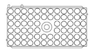
14 12.0 CONNECTOR FACES AND WIRE USAGE SCHEMATIC Techline Page 14 of 16 IS
15 Techline Page 15 of 16 IS
16 Techline Page 16 of 16 IS
Controls Pack Installation Manual
 1 M-6017-A504VB Please visit www.performanceparts.ford.com for the most current instruction and warranty information.!!! PLEASE READ ALL OF THE FOLLOWING INSTRUCTIONS CAREFULLY PRIOR TO INSTALLATION. AT
Controls Pack Installation Manual L 4V
 Please visit www.performanceparts.ford.com for the most current instruction and warranty information.!!! PLEASE READ ALL OF THE FOLLOWING INSTRUCTIONS CAREFULLY PRIOR TO INSTALLATION. AT ANY TIME YOU DO
Controls Pack Installation Manual L 4V
 Please visit www.fordperformanceracingparts.com for the most current instruction and warranty information.!!! PLEASE READ ALL OF THE FOLLOWING INSTRUCTIONS CAREFULLY PRIOR TO INSTALLATION. AT ANY TIME
NO PART OF THIS DOCUMENT MAY BE REPRODUCED WITHOUT PRIOR AGREEMENT AND WRITTEN PERMISSION OF FORD RACING PERFORMANCE PARTS
 Please visit www.fordracingparts.com for the most current instruction and warranty information. PLEASE READ ALL OF THE FOLLOWING INSTRUCTIONS CAREFULLY PRIOR TO INSTALLATION. AT ANY TIME YOU DO NOT UNDERSTAND
5.0L Co ntrols Pack Installation Manual/Automatic
 Please visit www.performanceparts.ford performanceparts.ford.com.com for the most current instruction and warranty information. PLEASE READ ALL OF THE FOLLOWING INSTRUCTIONS CAREFULLY PRIOR TO INSTALLATION.
Ford Racing 4.6L 3V Crate Engine Control Pack
 Ford Racing 4.6L 3V Crate Engine Control Pack Installation Time: 3-6 hours on a Foxbody Mustang Tools Required: Basic English and Metric Socket and Wrench Set Flat and Phillips Screwdrivers Torx bits Hammer
5.0L Controls Pack Insta llation Manual
 Please visit www.fordracingparts.com for the most current instruction and warranty information. PLEASE READ ALL OF THE FOLLOWING INSTRUCTIONS CAREFULLY PRIOR TO INSTALLATION. AT ANY TIME YOU DO NOT UNDERSTAND
Instruction Sheet 1 M T 2.3L Controls Pack
 Please visit https://performanceparts.ford.com for the most current instruction and warranty information. PLEASE READ ALL OF THE FOLLOWING INSTRUCTIONS CAREFULLY PRIOR TO INSTALLATION. AT ANY TIME YOU
SUM EFI Wiring Harness for GM LS1 Engine INSTALLATION INSTRUCTIONS
 SUM-890122 EFI Wiring Harness for GM LS1 Engine INSTALLATION INSTRUCTIONS 1 INTRODUCTION This harness is designed for GM 1997-2002 LS1 fuel injected engines utilizing a mechanical throttle body and throttle
M-9603-SVT mm Cold Air Kit w/premium Calibration INSTALLATION INSTRUCTIONS
 Please visit www.fordracingparts.com for the most current instruction information!!! PLEASE READ ALL OF THE FOLLOWING INSTRUCTIONS CAREFULLY PRIOR TO INSTALLATION. AT ANY TIME YOU DO NOT UNDERSTAND THE
Guardian GRD502-A Adapter Matrix
 Guardian GRD502-A Adapter Matrix Note: Based on vehicle age and transmission code, it may be necessary to use one of the adapters listed below along with the GRD501 or GRD502 part number. Adapter Application
SUM EFI Wiring Harness for GM LT-1/LT-4 Engine INSTALLATION INSTRUCTIONS
 SUM-890121 EFI Wiring Harness for GM LT-1/LT-4 Engine INSTALLATION INSTRUCTIONS INTRODUCTION This harness is designed for GM 1992-97 LT1/LT4 fuel injected engines. Even with minimal electrical experience,
V8 Gen. V Ford Mustang 2010 Update
 V8 Gen. V Ford Mustang 2010 Update There were several updates to the Ford Mustang in the 2010 model year. This document outlines the differences between the installation steps necessary for the 2010 Mustang
Remove black panel shown. Save 6 retaining pins for re-install later. Pry up on center part of pin first. Then pry out entire retaining pin.
 2005-2009 Ford Mustang V6 Fog Light Wiring Kit Parts List: Quantity: Tools Required: Wiring harness 1 Flat head screwdriver Supplemental wire leads 2 Ratchet & Socket set OR Wire tap red 2 Adjustable Wrench
RECOMMENDED TOOLS PERSONAL & VEHICLE PROTECTION SAFETY GLASSES
 2014 FORD TRANSIT FULL SIZE PART NUMBER: 250-9636 GENERAL APPLICABILITY THIS CRUISE WAS TESTED AND VERIFIED ON: FORD TRANSIT 150, 250 RECOMMENDED TOOLS PERSONAL & VEHICLE PROTECTION SAFETY GLASSES KIT
FOG LAMPS INSTALL KIT
 FOG LAMPS INSTALL KIT PT CRUISER INSTALLATION INSTRUCTIONS Read entire instructions thoroughly before starting. For proper aiming of fog lamps, follow procedures in the service manual. NOTES: Left and
SPEED CONTROL 4 AND 6 CYL. JEEP WRANGLER. Read entire instructions thoroughly before starting. INSTALLATION INSTRUCTIONS TOOLS REQUIRED:
 Read entire instructions thoroughly before starting. TOOLS REQUIRED: SPEED CONTROL 4 AND 6 CYL. JEEP WRANGLER INSTALLATION INSTRUCTIONS Complete socket set Phillips screwdriver Torx drivers Wire strippers/cutters
C FORD F250 / F L POWERSTROKE DIESEL WITH AUTOMATIC TRANSMISSIONS ONLY
 EXHAUST BRAKES C40019 1999-2003 FORD F250 / F350 7.3L POWERSTROKE DIESEL WITH AUTOMATIC TRANSMISSIONS ONLY Getting Started Thank you and congratulations on your purchase of a Pacbrake exhaust retarder.
Banks SmartLock. THIS MANUAL IS FOR USE WITH system 55270
 owner s manual with installation instructions Banks SmartLock 2003-Early 2004 Dodge 5.9L CUMMINS TURBO DIESEL TRUCKS THIS MANUAL IS FOR USE WITH system 55270 Gale Banks Engineering 546 Duggan Avenue Azusa,
RECOMMENDED TOOLS PERSONAL & VEHICLE PROTECTION SAFETY GLASSES
 HYUNDAI ACCENT 2010- /ELANTRA 2012- / KIA RIO 2012- PART NUMBER: 250-9628-NS GENERAL APPLICABILITY THIS CRUISE WAS TESTED AND VERIFIED ON: (AT/MT) VEHICLES RECOMMENDED TOOLS PERSONAL & VEHICLE PROTECTION
Installation Instructions for Lingenfelter GM 2500 Suburban & Yukon XL Auxiliary Fan System (with ECM controlled fan output)
") Installation Instructions for Lingenfelter 2007-2013 GM 2500 Suburban & Yukon XL Auxiliary Fan System (with ECM controlled fan output) PN L300090607 Revision - 1.1 Lingenfelter Performance Engineering
Installation Instructions for Lingenfelter 2007-2013 GM 2500 Suburban & Yukon XL Auxiliary Fan System (with ECM controlled fan output) PN L300090607 Revision - 1.1 Lingenfelter Performance Engineering
SPEED CONTROL 4 AND 6 CYL. JEEP WRANGLER. Read entire instructions thoroughly before starting. INSTALLATION INSTRUCTIONS TOOLS REQUIRED:
 Read entire instructions thoroughly before starting. TOOLS REQUIRED: SPEED CONTROL 4 AND 6 CYL. JEEP WRANGLER INSTALLATION INSTRUCTIONS Complete socket set Phillips screwdriver Torx drivers Wire strippers/cutters
PIMP Ford 5.0 Harness Installation Manual. Part Number: PM-75
 PIMP Ford 5.0 Harness Installation Manual Part Number: PM-75 Ron Francis Wiring 200 Keystone Rd Suite 1 Chester, PA 19013 800-292-1940 www.ronfrancis.com Pre-Installation Notes: This system is designed
ISIS Power Manual and Installation Guide Race Car Replicas- Superlite Coupe
 ISIS Power Manual and Installation Guide Race Car Replicas- Superlite Coupe Table of Contents Overview... 2 System Details... 3 Kit Includes... 3 Technical Specifications... 3 Harness Descriptions... 4
INSTALLATION INSTRUCTIONS
 INSTALLATION INSTRUCTIONS Accessory Application Publications No. CIVIC AII 24171 S 2- AND 4-DOOR Issue Date (DX, HX) AUG 2002 NOTE: Fog Lights cannot be installed if the vehicle is equipped with an optional
Speed Sentinel Programmable Road Speed Limiter
 An ISO 9001:2008 Registered Company Speed Sentinel Programmable Road Speed Limiter SS531-A, SS531-AX, SS531-AND Ford E Series 2005-2012 Ford F Series 2008-2010 Ford Crown Victoria 2005-2008 Contact InterMotive
INSTALLATION INSTRUCTIONS
 INSTALLATION INSTRUCTIONS Accessory Application Publications No. P/N 08E49-S2A-100 2004 S2000 AII 26325 Issue Date OCT 2003 PARTS LIST Hood switch harness TOOLS AND SUPPLIES REQUIRED #2 Phillips screwdriver
INSTALLATION INSTRUCTIONS
 Rear Vision System Mirror Display Dodge Ram Kit Contents: Instruction Sheets Template Chassis Harness Endgate Handle with Camera Wire Ties (Qty: 17) Bottle of ZTech Plug for Non-Locking Endgates (Optional)
GM VORTEC Drive by Wire Electronic Fuel Injection Wiring Harness HAR-1014
 GM VORTEC Drive by Wire Electronic Fuel Injection Wiring Harness HAR-1014 PERFORMANCE SYSTEMS INTEGRATION 170 Oberlin Ave N Suite 13 Lakewood NJ 08701-4548 Ph: 732-444-3277 Email: INFO@PSIConversion.com
PERFORMANCE SYSTEMS INTEGRATION
 2006 Current GEN IV LSX/Vortec 4.8, 5.3, 6.0, 6.2, 7.0 Drive by Wire (58X) Electronic Fuel Injection Wiring Harness w/ Manual or Non- Electronic Automatic Transmission HAR-10 (See Below) (P/N HAR- 1035,
TELORVEK EFI 5.0 Coyote Sequential Fuel Injection System Part # CY-11
 Page #1 TELORVEK EFI 5.0 Coyote Sequential Fuel Injection System Part # CY-11 WIRING INSTRUCTIONS Thank you for purchasing the absolute finest of wiring kits for the Ford Motor Co. Coyote modular engine.
Your Legal Fuel Tank Source.
 February 23, 2015 IS# 808 Page 1 of 13 THANK YOU FOR PURCHASING A TRANSFER FLOW 40 GALLON TOOLBOX REFUELING SYSTEM. PLEASE READ THE FOLLOWING PROCEDURES CAREFULLY BEFORE STARTING THE INSTALLATION. CAUTION:
INSTALLATION INSTRUCTIONS
 Rear Vision System Liftgate Emblem Camera Mirror Display 2009-2012 Ford Flex (Kit part number 1008-9527) Kit Contents: Mirror Liftgate Emblem Mount with Camera Interior (shorter) Harness Chassis (longer)
M-9424-M50CJ INTAKE MANIFOLD INSTALLATION INSTRUCTIONS
 Please visit www.fordracingparts.com for the most current instruction information!!! PLEASE READ ALL OF THE FOLLOWING INSTRUCTIONS CAREFULLY PRIOR TO INSTALLATION. AT ANY TIME YOU DO NOT UNDERSTAND THE
AviStart 3000 Installation Manual
 Table of Contents Important Information... 2 Recommended Installation Tools... 2 Recommended Procedures... 2 Main Wiring Diagram... 3 12 Pin Connector... 4 6 Pin Connector... 4 Installation Procedures...5
RECOMMENDED TOOLS PERSONAL & VEHICLE PROTECTION SAFETY GLASSES
 GENERAL APPLICABILITY FORD FIESTA ( AT/MT) KIT CONTENTS/SERVICE PARTS ITEM QTY DESCRIPTION PART# 1 1 CRUISE CONTROL MODULE 250-2813 2 1 SWITCH HARNESS 250-2760 3 1 PEDAL INTERFACE HARNESS 250-2821 4 1
Part Number:
 General Applicability This cruise control was tested and verified on: 2009-2010 Ford F-150 / E-150 2010 Ford Escape 2009-2010 Mazda Tribute This cruise control may not function correctly on unverified
AviStart 6500 Installation Manual
 Table of Contents Important Information... 1 Recommended Installation Tools... 1 Recommended Procedures... 1 Main Wiring Diagrams.... 2 Pin Connectors... 5 Installation Procedures...7 Control Unit... 7
TOYOTA im INTERIOR LIGHT KIT Preparation
 Preparation Part Number: PT922-12170 Kit Contents Item # Quantity Reqd. Description 1 1 Main Wire Harness 2 1 Switch 3 1 Switch Header 4 1 ECU 5 1 ECU Bracket 6 1 Hardware Kit 7 1 Instruction Card 8 1
INSTALLATION & OWNER S MANUAL
 1 of 18 INSTALLATION & OWNER S MANUAL (*Not including cab & other accessories) A/C Alternator Kit: Yamaha Drive & Drive2 P/N: 1ACYDR2DRK Recommended it be installed with Curtis Cab: Sandstone (p/n 1GCYD1-A,
Depress each tab as you pull the bezel off. The bezels are tight. L.H. shown.
 2013-2014 Ford Mustang V6 & Boss 302 Lower Valance Fog Light Kit Parts List: Quantity: Tool List: Fog light & bulb with bracket 2 Flat head & Phillips screwdriver Black bezels 2 Ratchet & Socket set OR
Not Included. Rear Half Harness
 Basic Light Kit 60102 Caution! Wear appropriate eye protection! Disconnect the battery or batteries. Place run/tow switch in tow position before disconnecting the batteries on models using that feature.
KIA RIO CRUISE CONTROL INSTALLATION INSTRUCTIONS PART NO AUTOMATIC TRANSMISSION VEHICLE CONTENTS
 2007-2008 KIA RIO AUTOMATIC TRANSMISSION VEHICLE CRUISE CONTROL INSTALLATION INSTRUCTIONS PART NO. 250-1799 CONTENTS PARTS IDENTIFICATION... 2 HELPFUL HINTS... 3 INSTALLATION... 4 WIRING DIAGRAM... 11
Installation Instructions for Lingenfelter GM 2500 Suburban & Yukon XL Auxiliary Fan System (with AC clutch controlled fan output)
") Installation Instructions for Lingenfelter 2007-2013 GM 2500 Suburban & Yukon XL Auxiliary Fan System (with AC clutch controlled fan output) PN L300080607 Revision - 1.1 Lingenfelter Performance Engineering
Installation Instructions for Lingenfelter 2007-2013 GM 2500 Suburban & Yukon XL Auxiliary Fan System (with AC clutch controlled fan output) PN L300080607 Revision - 1.1 Lingenfelter Performance Engineering
M-9603-CJ 123 mm Cold Air Kit for 5.4L 4V V8 Cobra Jet Mustang INSTALLATION INSTRUCTIONS
 Please contact the Techline for the most current instruction information 1-800-367-3788.!!! PLEASE READ THE FOLLOWING INSTRUCTIONS CAREFULLY PRIOR TO INSTALLATION!!! OVERVIEW: This kit is designed for
RECOMMENDED TOOLS PERSONAL & VEHICLE PROTECTION SAFETY GLASSES
 PART NUMBER: 250-9625 GENERAL APPLICABILITY THIS CRUISE WAS TESTED AND VERIFIED ON: ALL MODELS RECOMMENDED TOOLS PERSONAL & VEHICLE PROTECTION SAFETY GLASSES KIT CONTENTS/SERVICE PARTS ITEM QTY DESCRIPTION
PRXB EXHAUST BRAKE MAXIMUM EXHAUST FLOW DESIGN
 MAXIMUM EXHAUST FLOW DESIGN PRXB EXHAUST BRAKE C44072/C44073/C44074/C44075/C44076 APPLICATION: 994-2002 DODGE RAM TRUCKS W/5.9L CUMMINS DIESEL ENGINES WITH MANUAL & AUTOMATIC TRANSMISSIONS STOCK DODGE
Dodge Cummins Positive Air Shutoff
 1 INSTALL MANUAL 2010-2012 6.7 Dodge Cummins Positive Air Shutoff P/N# 1036722 P/N# 1036722-M UPLEASE READ ALL INSTRUCTIONS BEFORE INSTALLATION An Information decal has been provided in this kit. This
RECOMMENDED TOOLS PERSONAL & VEHICLE PROTECTION SAFETY GLASSES
 PART NUMBER: 250-9631 GENERAL APPLICABILITY THIS CRUISE WAS TESTED AND VERIFIED ON: ALL MODELS (AT/MT) RECOMMENDED TOOLS PERSONAL & VEHICLE PROTECTION SAFETY GLASSES KIT CONTENTS/SERVICE PARTS ITEM QTY
WOT Box Installation Instructions VW / Audi
 Connector Pinout Pin Color AWG Name WOT Box Installation Instructions VW / Audi Description 1 Yellow 18 RPM Connect to Fuel Injector Drive Signal or Ignition Control Signal (varies by car model) 2 Black
RECOMMENDED TOOLS PERSONAL & VEHICLE PROTECTION SAFETY GLASSES
 PART NUMBER: 250-9545 GENERAL APPLICABILITY THIS CRUISE WAS TESTED AND VERIFIED ON:2.7,3.3, 3.5, 5.0 FORD F-150 RECOMMENDED TOOLS PERSONAL & VEHICLE PROTECTION SAFETY GLASSES KIT CONTENTS/SERVICE PARTS
M-9603-SVT mm Cold Air Kit w/premium Calibration INSTALLATION INSTRUCTIONS
 Please contact the Tech Line for the most current instruction information (800) 367-3788.!!! PLEASE READ THE FOLLOWING INSTRUCTIONS CAREFULLY PRIOR TO INSTALLATION!!! OVERVIEW: This kit is designed for
INSTALLATION INSTRUCTIONS
 OEM Recessed Lip Camera with Harness and Slimline Mirror (Kit part number 9002-8724) Please read thoroughly before starting installation and check that kit contents are complete. Items Included in the
90558 Installation Manual For # Cummins 5.9L Common Rail Diesel
 2501 Ludelle Street Fort Worth, Texas 76105 817-244-6212 Phone 817-244-4024 Fax 888-350-6588 Sales 800-423-9696 Tech E-mail: painless@painlessperformance.com Web: www.painlessperformance.com 90558 Installation
INSTALLATION INSTRUCTIONS
 OEM Recessed Lip Camera with Harness and Auto Dimming Mirror (Kit part number 9002-8721) Please read thoroughly before starting installation and check that kit contents are complete. Items Included in
DirectMount EXHAUST BRAKES
 DirectMount EXHAUST BRAKES APPLICATION: Fixed Orifice and PRXB Exhaust Brakes 2003 2005 Dodge Trucks with 3.5" & 4" Exhaust and 47RE & 48RE Automatic Transmissions Only Vehicles with an existing air compressor
2010 FORD TRANSIT ELECTRONIC CRUISE KIT Part Number:
 General Applicability Recommended Tools Item # Qty. Description 1. 250-2758 1 Cruise Control Module 2. 250-2760 1 Switch Harness 3. 250-2759 1 Main Wiring Harness 4. 250-2771 1 Pedal Interface Harness
Guardian GRD501-AR Adapter Matrix
 An ISO 9001:2008 Registered Company Guardian GRD501-AR Adapter Matrix Note: Based on vehicle age and transmission code, it may be necessary to use one of the adapters listed below along with the GRD501
Vortec Drive by Cable Electronic Fuel Injection Wiring Harness (P/N HAR-1018) HAR-1018
 HAR-1018") 1998 2002 Vortec Drive by Cable Electronic Fuel Injection Wiring Harness (P/N HAR-1018) HAR-1018 PERFORMANCE SYSTEMS INTEGRATION 170 Oberlin Ave N Suite 13 Lakewood NJ 08701-4548 Ph: 732-444-3277 Email:
1998 2002 Vortec Drive by Cable Electronic Fuel Injection Wiring Harness (P/N HAR-1018) HAR-1018 PERFORMANCE SYSTEMS INTEGRATION 170 Oberlin Ave N Suite 13 Lakewood NJ 08701-4548 Ph: 732-444-3277 Email:
Idle Timer Controller - A-ITC520-A Ford E Series Ford F250 - F Ford F250 - F550 (*B-ITC520-A) F650/F750
 F650/F750") An ISO 9001:2008 Registered Company Idle Timer Controller - A-ITC520-A 2009-2018 Ford E Series 2008-2016 Ford F250 - F550 2017-2018 Ford F250 - F550 (*B-ITC520-A) 2016-2018 F650/F750 *Uses the Ford 24-Pin
An ISO 9001:2008 Registered Company Idle Timer Controller - A-ITC520-A 2009-2018 Ford E Series 2008-2016 Ford F250 - F550 2017-2018 Ford F250 - F550 (*B-ITC520-A) 2016-2018 F650/F750 *Uses the Ford 24-Pin
RECOMMENDED TOOLS PERSONAL & VEHICLE PROTECTION SAFETY GLASSES
 MITSUBISHI MIRAGE 2013- PART NUMBER: 250-9633 GENERAL APPLICABILITY ALL MODELS RECOMMENDED TOOLS PERSONAL & VEHICLE PROTECTION SAFETY GLASSES KIT CONTENTS/SERVICE PARTS ITEM QTY DESCRIPTION PART# 1 1 CRUISE
Installation Instructions General Motors 8.1 Sequential Vapor Injection (S.V.I.) System 7500/6500 Series Trucks model year.
 System 7500/6500 Series Trucks model year.") Installation Instructions General Motors 8.1 Sequential Vapor Injection (S.V.I.) System 7500/6500 Series Trucks 2003-2005 model year. Technocarb Equipment (2004) Ltd. 4-30435 Progressive Way Abbotsford,
Installation Instructions General Motors 8.1 Sequential Vapor Injection (S.V.I.) System 7500/6500 Series Trucks 2003-2005 model year. Technocarb Equipment (2004) Ltd. 4-30435 Progressive Way Abbotsford,
RECOMMENDED TOOLS PERSONAL & VEHICLE PROTECTION SAFETY GLASSES
 PART NUMBER: 250-9625 GENERAL APPLICABILITY THIS CRUISE WAS TESTED AND VERIFIED ON: ALL MODELS RECOMMENDED TOOLS PERSONAL & VEHICLE PROTECTION SAFETY GLASSES KIT CONTENTS/SERVICE PARTS ITEM QTY DESCRIPTION
TELORVEK EFI. 4S. S e. n s tem. a l Fue l I n j e cti
 Page #1 4.63 V &5 TELORVEK EFI. 4S /C S e q uen i t a l Fue l I n j e cti o n Sy s tem MG-05 / MG-05A WIRING INSTRUCTIONS Thank you for purchasing the absolute finest of wiring kits for the Ford Motor
RECOMMENDED TOOLS PERSONAL & VEHICLE PROTECTION SAFETY GLASSES
 HYUNDAI ACCENT 2012-18 /ELANTRA 2012-16 / KIA RIO 2012-2018 KIO FORTE 2014-18 PART NUMBER: 250-1862 GENERAL APPLICABILITY THIS CRUISE WAS TESTED AND VERIFIED ON: (AT/MT) VEHICLES RECOMMENDED TOOLS PERSONAL
M-9603-GTB 85 mm Cold Air Kit w/premium Cal. for 4.6L 3V V8 Mustang INSTALLATION INSTRUCTIONS
 Please contact the Techline for the most current instruction information 800-367-3788.!!! PLEASE READ THE FOLLOWING INSTRUCTIONS CAREFULLY PRIOR TO INSTALLATION!!! OVERVIEW: This kit is designed for use
Idle Timer Controller - ITC515-A Ford Transit Contact InterMotive for additional vehicle applications
 An ISO 9001:2008 Registered Company Idle Timer Controller - ITC515-A 2015-2018 Ford Transit Contact InterMotive for additional vehicle applications Overview The ITC515-A system will shut off gas or diesel
INSTALLATION INSTRUCTIONS
 Rear Vision System Tailgate Emblem Camera Mirror Display 2009-Current Ford F-150 and 2010-Current Super Duty (Kit part number 1008-9527) Kit Contents: Mirror Tailgate Emblem Mount with Camera Interior
ENGINE DISPLACEMENT 2000 NUMBER OF VALVES 16 ENGINE SET NUMBER
 MANUFACTURER Subaru TYPE Forester ENGINE DISPLACEMENT 2000 NUMBER OF VALVES 16 ENGINE CODE / NUMBER FA20 DIT VEHICLE CATEGORIES M TRANSMISSION AT VERSION Direct LiquiMax-2.1 PETROL ECU MANUFACTURER / CODE
Special Note About The JDM High Performance Water Pump:
 Page 1 of 30 JDM Engineering, Inc. home Call Us! 732-780- 0770 back to Installation Instructions Electric Fan Upgrade Kit Electric Fan Wiring Diagram Thank you for your purchase of the JDM Engineering
RECOMMENDED TOOLS PERSONAL & VEHICLE PROTECTION SAFETY GLASSES
 PART NUMBER: 250-9627 GENERAL APPLICABILITY THIS CRUISE WAS TESTED AND VERIFIED ON: ALL MODELS (AT/MT) RECOMMENDED TOOLS PERSONAL & VEHICLE PROTECTION SAFETY GLASSES KIT CONTENTS/SERVICE PARTS ITEM QTY
'05- 'Current LS2/LS3 Drive by Cable Electronic Fuel Injection Wiring Harness HAR-1058
 '05- 'Current LS2/LS3 Drive by Cable Electronic Fuel Injection Wiring Harness HAR-1058 PERFORMANCE SYSTEMS INTEGRATION 170 Oberlin Ave N Suite 13 Lakewood NJ 08701-4548 Ph: 732-444-3277 Email: INFO@PSIConversion.com
NO PART OF THIS DOCUMENT MAY BE REPRODUCED WITHOUT PRIOR AGREEMENT AND WRITTEN PERMISSION OF FORD PERFORMANCE PARTS
 Please visit www. performanceparts.ford.com for the most current instruction and warranty information. PLEASE READ ALL OF THE FOLLOWING INSTRUCTIONS CAREFULLY PRIOR TO INSTALLATION. AT ANY TIME YOU DO
PRXB EXHAUST BRAKE HIGH PERFORMANCE
 HIGH PERFORMANCE PRXB EXHAUST BRAKE C44059, C4406, C44063, C44065 APPLICATION 994-2002 DODGE RAM AUTOMATIC TRUCKS EQUIPPED WITH 47RE TRANSMISSIONS WITH 5.9L, 24 VALVE CUMMINS DIESEL ENGINES GETTING STARTED
Procharger Stage II Intercooled Supercharger System (11-14 GT)
") Procharger Stage II Intercooled Supercharger System (11-14 GT) Installation Time: Approximately one day. Installed on 2012 Mustang GT 5.0/Manual Required Tools 3/8 Socket Set (Standard and Metric) 1/2
Procharger Stage II Intercooled Supercharger System (11-14 GT) Installation Time: Approximately one day. Installed on 2012 Mustang GT 5.0/Manual Required Tools 3/8 Socket Set (Standard and Metric) 1/2
Keyless Upgrade Alarm
 Toyota Matrix 009 - Keyless Upgrade Alarm Part Number: 0006-940 Accessory Code: QS Kit Contents Item # Quantity Reqd Description Security Module Shock Sensor 3 LED Valet Switch 4 HP Switch Ext. 5 Window
Speed Sentinel II Programmable Road Speed Limiter
 An ISO 9001:2008 Registered Company Speed Sentinel II Programmable Road Speed Limiter SS501-A, SS501-AX Ford E Series 2005-2008 Ford F250-F550 Series 2008-2010 Ford Crown Victoria 2005-2008 Contact InterMotive
MAKE OF AUTOMOBILE: TYPE: V 70 PISTON DISPLACEMENT: 2521 NUMBER OF VALVES:
 MAKE OF AUTOMOBILE: TYPE: V 70 PISTON DISPLACEMENT: 2521 NUMBER OF VALVES: 20V ENGINE NUMBER: B5254T TRANSMISSION TYPE ( MT / AT ) AT VEHICLE CATEGORIES M or N PASSENGER CAR ( M ) TYPE VSI INJECTOR (COLOUR
2002 ENGINE PERFORMANCE. Self-Diagnostics - RAV4. Before performing testing procedures, check for any related Technical Service Bulletins (TSBs).
.") 2002 ENGINE PERFORMANCE Self-Diagnostics - RAV4 INTRODUCTION NOTE: Before performing testing procedures, check for any related Technical Service Bulletins (TSBs). To properly diagnosis and repair this
2002 ENGINE PERFORMANCE Self-Diagnostics - RAV4 INTRODUCTION NOTE: Before performing testing procedures, check for any related Technical Service Bulletins (TSBs). To properly diagnosis and repair this
A selection of phillips head screwdrivers 15mm socket 10mm socket Modeler s knife Solder Electrical tape A selection of flat head screwdrivers
 Read entire instructions thoroughly before starting. References to the service manual wiring diagrams and operation sections will be required for adjustments, fastener torques, and troubleshooting. TOOLS
Small knife. Remove black panel shown. Save 6 retaining pins for re-install later.
 2005-2009 Ford Mustang V6 Fog Light Wiring Kit Parts List: Quantity: Tools Required: Wiring harness 1 Flat head screwdriver PB-3425 Parts Bag 1 Ratchet & Socket set OR Ford OEM Switch (if you 1 Adjustable
INSTALLATION INSTRUCTIONS
 INSTALLATION INSTRUCTIONS Accessory Application Publications No. S CIVIC 2 AND 4-DOOR (EX, LX) AII 24188 Issue Date AUG 2002 NOTE: Fog Lights cannot be installed if the vehicle is equipped with an optional
Hot Rod Coyote Engine
 Part Number: 33871 Revision:W Effective Date: 03/26/19 By: J. INGERSLEV Document Type (indicate): Bill of Material Drawing (may be attached) Specification Assembly Instructions Operating Procedure Other
2004 KIA RIO CRUISE CONTROL INSTALLATION INSTRUCTIONS PART NO AUTOMATIC TRANSMISSION VEHICLE CONTENTS
 2004 KIA RIO AUTOMATIC TRANSMISSION VEHICLE CRUISE CONTROL INSTALLATION INSTRUCTIONS PART NO. 250-1766 CONTENTS PARTS IDENTIFICATION... 2 HELPFUL HINTS... 3 INSTALLATION... 4 WIRING DIAGRAM... 11 TROUBLESHOOTING
NISSAN TRUCKS ELECTRONIC CRUISE CONTROL KIT AUTOMATIC & MANUAL TRANSMISSIONS PART NUMBER:
 General Applicability This cruise control was tested and verified on: 2008-2011 Nissan Frontier 2008-2011 Nissan Titan This cruise control may not function correctly on unverified vehicles. See www.rostra.com
OEM Lip Mount Camera with Harness and OnStar Mirror for GM Vehicles with 16-pin Mirror Connector (Kit part number )
") OEM Lip Mount Camera with Harness and OnStar Mirror for GM Vehicles with 16-pin Mirror Connector (Kit part number 9002-8722) Please read thoroughly before starting installation and check that kit contents
OEM Lip Mount Camera with Harness and OnStar Mirror for GM Vehicles with 16-pin Mirror Connector (Kit part number 9002-8722) Please read thoroughly before starting installation and check that kit contents
M-6066-SGT (Black)/M-6066-SGTP (Polished) SVT Mustang Supercharger Upgrade Kit INSTALLATION INSTRUCTIONS
/M-6066-SGTP (Polished) SVT Mustang Supercharger Upgrade Kit INSTALLATION INSTRUCTIONS") Please contact the Techline for the most current instruction information (800) FORD788.!!! PLEASE READ THE FOLLOWING INSTRUCTIONS CAREFULLY PRIOR TO INSTALLATION!!! OVERVIEW: This kit is designed for use
Please contact the Techline for the most current instruction information (800) FORD788.!!! PLEASE READ THE FOLLOWING INSTRUCTIONS CAREFULLY PRIOR TO INSTALLATION!!! OVERVIEW: This kit is designed for use
LSx Harness Installation. lsxeverything.com #BecauseYouShould
 LSx Harness Installation lsxeverything.com #BecauseYouShould Table of Contents Slide 1 Introduction Page Slide 2 Table of Contents Slide 3 Starting Instructions Slide 4 Power Connections Slide 5 Ground
ULTRACRUISE CONTROL INSTALLATION MANUAL
 ULTRACRUISE CONTROL INSTALLATION MANUAL Installation Operation Trouble Shooting FORM # 2784 Rev. A 07/95 THIS MANUAL, YOUR KIT AND YOU This Cruise Control Kit is a microprocessor based Cruise Control.
SVE BULLETIN and later Transit Stationary Elevated Idle Control
 Q-239 2016 and later Transit Stationary Elevated Idle Control Models Affected All 2016 and later Model Year Transit Vans, Wagons, Cutaways, and Chassis Cab Vehicles. Purpose To explain changes and functions
Installation and Operation Guide. Tundra HD 2500 Power Inverter. for the. Webasto BlueCool Truck System
 Installation and Operation Guide Tundra HD 2500 Power Inverter for the Webasto BlueCool Truck System www.tundrainternational.com www.techwebasto.com BCTSP0063A Table of Contents 1. Introduction 4 1.1 Disclaimer.................................................................................
jegs.com
 Contents Wiring Harness w/ Fuse Panel Installation Instructions Turn Signal Plug w/ Terminals 2 Headlight Plugs 3/4 Grommet 10 ¼ Terminals 4 Ring Terminals 10 Wire Ties Fusible Link 2 Screws & Nuts 2 Plastic
IT IS IMPORTANT THAT YOU OBTAIN THE CORRECT INFORMATION FOR YOUR VEHICLE, OR DAMAGE TO THE WIRING SYSTEM COULD OCCUR.
 Instructions for Universal Harness PRINT THESE INSTUCTIONS Gentex Mirror Installation Instructions Provided by www.rearviewautomirrors.com These instructions have been prepared to provide you with details
Aftermarket Interface Module
 An ISO 9001:2008 Registered Company Aftermarket Interface Module (2015-2018 Ford Transit) AIM514-B High Side Solenoid type Coolant Valve Control AIM515-B Motor Reversing type Coolant Valve Control Introduction
HOWELL INSTALLATION MANUAL. Tuned Port Or LT-1 Fuel Injection Harness ( )
") HOWELL ENGINE DEVELOPMENTS, INC. FUEL INJECTION APPLICATIONS INSTALLATION MANUAL Tuned Port Or LT-1 Fuel Injection Harness (1985-1992) Howell Engine Developments, Inc. 6201 Industrial Way Marine City,
HOWELL ENGINE DEVELOPMENTS, INC. FUEL INJECTION APPLICATIONS INSTALLATION MANUAL Tuned Port Or LT-1 Fuel Injection Harness (1985-1992) Howell Engine Developments, Inc. 6201 Industrial Way Marine City,
MUSTANG GT
 MAXFLOW FUEL PUMP BOOSTER Installation Instructions 2011-2012 MUSTANG GT P/N: 5A102-029 ENGINEERING, INC. 1650 Pacific Avenue, Channel Islands, CA 93033-9901 Phone 805 247-0226 Fax: 805 247-0669 www.vortechsuperchargers.com
VORTEC Drive by Wire Electronic Fuel Injection Wiring Harness HAR-1085
 2001 2002 VORTEC Drive by Wire Electronic Fuel Injection Wiring Harness HAR-1085 PERFORMANCE SYSTEMS INTEGRATION 170 Oberlin Ave N Suite 13 Lakewood NJ 08701-4548 Ph: 732-444-3277 Email: INFO@PSIConversion.com
3 December Cool Down Timer 2 Page 1. Application Chart --
 3 December 2012 1081160 - Cool Down Timer 2 Page 1 BD Cool Down Timer 2 Part# 1081160 Application Chart -- Dodge Cummins (5.9/6.7) 1994-2008 Ford F Series (6.0/6.4/7.3L) 1994-2008 GMC/Chevy Duramax 2001-2009
Speed-Pro EFI Installation Manual
 Speed-Pro EFI Installation Manual Speed-Pro Electronics Installation Manual Page The wiring harness is labeled on each of the connectors to simplify installation. Your application may not require the use
CA 421 Installation Instructions
 CA 421 Installation Instructions PROFESSIONAL INSTALLATION STRONGLY RECOMMENDED Installation Precautions: Roll down window to avoid locking keys in vehicle during installation Avoid mounting components