PRXB EXHAUST BRAKE MAXIMUM EXHAUST FLOW DESIGN
|
|
|
- Muriel Hillary Pierce
- 6 years ago
- Views:
Transcription


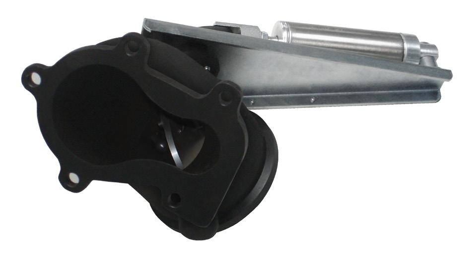

1 MAXIMUM EXHAUST FLOW DESIGN PRXB EXHAUST BRAKE C44072/C44073/C44074/C44075/C44076 APPLICATION: DODGE RAM TRUCKS W/5.9L CUMMINS DIESEL ENGINES WITH MANUAL & AUTOMATIC TRANSMISSIONS STOCK DODGE CUMMINS HX & HY SERIES TURBO


2 Thank you and congratulations on the purchase of a retarder. Before starting the installation, please read the entire installation manual carefully to ensure you can complete the installation once started. Check that your kit is correct for the application and contains all the necessary parts. NOTE: C44072, C44073, C44074, C44075 & C44076 kits will only work on vehicles using Stock Dodge Cummins HX & HY Series Turbos. For vehicles using an aftermarket turbo please consult for other kit options. APPLICATION NOTES: IMPORTANT: APPLICATION NOTES: IMPORTANT: C44072 is a High Performance PRXB Exhaust Brake kit designed to provide maximum retarding throughout the RPM range of your Dodge 2 valve Cummins with a manual shift transmission. C44073 is a High Performance PRXB Exhaust Brake kit designed to provide maximum retarding throughout the RPM range of your Dodge 2 valve Cummins with an automatic 47RH transmission. C44076 is a High Performance PRXB Exhaust Brake kit designed to provide maximum retarding throughout the RPM range of your Dodge 2 valve Cummins with an automatic 47RE transmission. Heavy Duty Exhaust Valve Springs ARE MANDATORY for all 2 valve engines, C400 Spring Kit is included in the kit. Failure to install H.D. Exhaust Valve Springs WILL result in engine Damage! C44074 is a High Performance PRXB Exhaust Brake kit designed to provide maximum retarding throughout the RPM range of your 998½-2002 Dodge 24 valve Cummins with a manual shift transmission. C44075 is a High Performance PRXB Exhaust Brake kit designed to provide maximum retarding throughout the RPM range of your 998½-2002 Dodge 24 valve Cummins with an automatic 47RE transmission ½ 24 valve engine vehicles only, as the exhaust brake signal from the ECM is not activated, Part #C4004 ECM Bypass is required. IMPORTANT: Trucks with aftermarket exhaust systems larger than stock 3 O.D. require a different exhaust adapter. (4" aftermarket exhaust systems require Part #C342). Contact C44072 C44074 C44075 C44073 C44076 OPTIONAL ACCESSORIES: Shifter Switches (Manual Tran) - C804 for M/Y C8040 for M/Y ECM Bypass Kit - C205 for M/ Y C4004 for M/Y ½ PG


3 C44072/C44074 Electrical Installation (Manual Transmission Vehicles) (for C44075/C44073/C44076, Auto Transmission Vehicles, proceed to step 7) Locate the main wiring harness supplied in the kit. Using the self tapping screws provided, mount the harness relays on the driver side inner fender between the ABS brake controller and the fuse panel. Install both relays. Route the orange wire of the harness through the firewall grommet to the inside of the cab. 2 ON/OFF Switch Installation: Provided on the last pages of this manual are 2 templates for dash switch locations. The 2 switch locations are suggestions. Consult with the customer for their preference before drilling a ½" hole to accommodate the switch. Vehicles equipped with manual transmissions can use a shift lever mounted switch for the driver s convenience ½ vehicles require the orange wire to be connected to the control switch before installing. Connect the wires to the control switch as shown in the schematic pertaining to your kit #, found on page Remove the dash panel below the steering column. At the base of the steering column, locate an ignition power supply models use a medium blue 4 gage wire, blue T tap models use a black with orange tracer 8 gage wire, red T tap Check the wire with a voltmeter to ensure it is 2 volts and an ignition power source. Attach the supplied T tap to this wire and insert the supplied 6 gage fused wire to this T tap. With the additional harness provided, connect the switch as shown in the wiring diagram pertaining to your kit #, found on page 2-6. Install the control switch and plate. 4 ECM Connection for Trucks using C44074 Kit Only: If using C205 ECM bypass, disregard this step and follow the instructions provided in the C205 kit. Disconnect both positive battery leads. Remove the two capscrews that attach the fuel filter head to the intake manifold. This should allow for enough clearance to access the 50 pin ECM connector. Locate pin 20 and remove the sealing plug. Be careful not to push the sealing pin into the connector. If this happens, use an Allen key to remove the ECM connector from the ECM, and use a small pick to push the sealing pin out from the backside. Route the black wire with special ECM pin to the ECM. Insert the black wire of the harness into pin 20 until it stops. Pull gently to make sure it is locked into the ECM connector PG 2
. Remove the nut and install the switch assembly with the switch arm horizontal. Reinstall the stud nut and tighten, making sure the switch arm is behind the accelerator lever.")

4 5 Throttle Switch Installation: C44072 Kit and 998½ Trucks (manual trans) using the C4004 Kit Only: Vehicles using ECM Connection, disregard this step Locate the stud shown in the photo (shown with arrow). Remove the nut and install the switch assembly with the switch arm horizontal. Reinstall the stud nut and tighten, making sure the switch arm is behind the accelerator lever. Adjust the switch by loosening the screws and positioning it to click just as the throttle returns to its released position. Cycle the throttle and listen for the click each time the throttle returns to idle. Tighten the screws when adjustment is complete. 5 Locate the black wire of the harness with the Cummins ECM pin, cut off this pin and attach the supplied black wire with a heat shrinkable butt connector. Route this wire in the cab through the firewall to the throttle switch. Crimp on the supplied spade terminal and connect this wire to the throttle switch terminal with the diode. Attach the leg of the orange wire (connected to the control switch in step 2) to the remaining terminal on the throttle switch. Consult the wiring schematic pertaining to your kit #, found on page C44072 and C44074 Kits Route the remaining harness along the firewall to the passenger side and then route it forward along the fender to the passenger side Battery. Make sure it is secured away from heat sources and moving parts using the supplied tie-straps. Proceed to step 8. C44073, C44075, C44076 ELECTRICAL INSTALLATION (C44072, C44074 kits, proceed to step 8) 7 Remove the lower dash panel and locate an ignition power supply at the base of the steering column models use a medium blue 4 gage wire, blue T tap models use a black with orange tracer 8 gage wire, red T tap Check the wire with a voltmeter to ensure it is 2 volts and an ignition power source. Attach the supplied T tap to this wire and insert the red 6 gage 3 amp fused wire to this T tap. 7 PG 3


5 8 Mount the control unit to the provided bracket on the inside of the firewall (under the dash - as shown in photo) using the factory stud and nut for the steering column. Once the control unit is fastened to the stud. Connect the grey and black connectors of the harness to the control unit. Secure the harness with the provided tie-straps. 8 9 Locate the plastic plate in the drivers side of the firewall. Drill a hole large enough to feed the harness through. Then, feed the harness into the engine compartment from the cab side. Apply silicon sealant around the loom to provide a seal. 9 0a ON/OFF Switch Installation: C44073, C44075 & C44076 Kits Only Provided on the last pages of this manual are 2 templates for dash switch locations. The 2 switch locations are suggestions only for specific years. Consult the customer for their preference before drilling a ¼" hole to accommodate the dash switch. 0 a 0b Install the dash switch and route the wires to the control unit. Secure the wires with the supplied tie-straps. At the control unit, locate the matching wire colors and connect using the supplied heat shrinkable red butt connectors. Once crimped, heat the connector to provide a water tight seal. Re-install the lower dash panel. 0 b PG 4
. *The battery leads are connected in step 26.")


6 Connect the black wire with the eye terminal to the negative battery terminal or a good chassis ground. Secure with the supplied tie-straps. Remove both the positive battery terminals. Route the red fused wire with the eye terminal to the positive battery terminal (leaving the positive lead disconnected). *The battery leads are connected in step Route the remaining harness along the firewall to the passenger side and then route it forward along the fender to the passenger side battery. Make sure it is secured away from heat sources and moving parts using the supplied tie-straps. C44075 kits, proceed to step 4. 3 Throttle Switch Installation: C44073, C44076 Kits Only Locate the stud shown in the photo and remove the nut. Install the switch assembly with the switch arm horizontal. Re-install the stud nut and tighten, making sure the switch arm is behind the accelerator lever. Adjust the switch by loosening the screws and positioning it to click just as the throttle returns to its released position. Cycle the throttle and listen for the click each time the throttle returns to idle. Tighten the screws when adjustment is complete. Locate the black wire and white wire of the harness, coming from the control unit. Attach the black wire to the terminal connected to the diode on the throttle switch. Connect the white wire to the other terminal on the throttle switch. Make sure it is secured away from heat and moving parts using the supplied tie-straps. Consult the wiring schematic pertaining to your kit #, found on page C44075 Kit Only: Under the hood, between the injection pump and the vacuum pump, locate the factory 3 pin Weather-Pac connector on the driver side of the engine (shown by the arrow). Remove the protective cap and install the mating connector in the harness. Install the removed protective cap on the unused connector on the harness - unless you have a performance module connected to it. If so, it connects to the connector. NOTE: Some 999 model year trucks and all 998½ will require the use of a 3 pin triangular jumper harness to connect to the data link connector. See schematic pertaining to your kit #, found on page 2-6. C44075 kits proceed to step PG 5


7 5 C44076 Kit Only: Locate the diagnostic connector under the dash on the drivers side. Connect the male plug of the harness to the factory diagnostic connector. Secure the connector to the diagnostic connector using the supplied tie straps. 6 a 6 C44075 & C44076: Remove the air filter housing to access the passenger side firewall, locate the PCM (shown in fig 6b). Remove the C2 and C3 connectors. Remove the plastic cover to access the wires. Pull back the conduit to give access for attaching wires into the factory harness. Use fig 6bb as a guide to the pin locations. C3 C2 C 6 b C2 Connections Locate the orange/black wire in pin of the C2 connector. Cut this wire. Attach the brown wire of the harness to the PCM side. Attach the orange wire to the harness side of the orange/black wire. These connections are done using the supplied red heat shrinkable butt connectors. Locate the brown wire in pin 2 of the C2 connector. Cut this wire and splice the blue wire of the harness into it using the supplied red heat shrinkable butt connectors. POWERTRAIN MODULE C2 (DIESEL) bb C3 Connections Locate the orange/white wire in pin 3 of the C3 connector. Cut this wire and splice the yellow wire of the harness into it using the supplied red heat shrinkable butt connectors. Using a heat gun, heat the connectors to provide a water tight seal on all heat shrinkable butt connectors. See the wiring diagram pertaining to your kit #, found on page 2-6. POWERTRAIN MODULE C3 (DIESEL) 22 2 Powertrain Control Powertrain Control a C44073 Kit Only: Route the brown, orange, blue, yellow and the OBD connector of the harness along the firewall to the passenger side firewall. Locate the factory OBD connector, connect it to the mating connector and apply electrical tape to secure them together. Remove the air filter housing to gain access to the PCM. 7 a PG 6


8 7b C44073 Kit Only: On the passenger side firewall, locate the PCM (shown in fig 7b). Remove the connector by loosening the bolt in the center. Remove the plastic cover to access the wires. Pull back the conduit to give access for attaching wires into the factory harness. Use fig 7bb as a guide to the pin locations. 7 b Locate the orange/black wire in pin 54 of the PCM connector. Cut this wire. Attach the brown wire of the harness to the PCM side. Attach the orange wire to the harness side of the orange/black wire. These connections are done using the supplied red heat shrinkable butt connectors. Locate the brown wire in pin 55. Cut this wire and splice the blue wire of the harness into it using the supplied red heat shrinkable butt connectors. Locate the orange/white wire in pin 0. Cut this wire and splice the yellow wire of the harness into it using the supplied red heat shrinkable butt connectors. 2 4 view shown is of the PCM side, connector removed POWERTRAIN CONTROL MODULE 7 bb See wiring diagram pertaining to your kit #, found on page Consult with the customer for their preferred location to mount the quick disconnect for the airline. The mounting location should be in a clean, dry area with easy access to the operator. See photo in step 9 for suggested location. 8 Using the two self tapping screws, mount the L bracket. Insert the bulkhead airline fitting into the L bracket and tighten the jam nut to secure it. Follow the airline installation procedures in the next step. Make sure the nylon is cut square on each end and is pushed into the fittings until it clicks. 9 Shown in the photo is a suggested location marked A.Connect one end of the remaining air line into the quick connect assembly, route this to the remaining fitting at the compressor. Mount the air inlet filter in a cool dry location. Suggested location is shown in photo, marked with B Locate the blue nylon airline provided, to the filter housing, route the other end to the compressor inlet fitting located on the compressor body. (compressor is installed in step 20) Make sure the nylon hose is cut square on each end and is pushed into the fittings until it clicks. PG 7


9 C44072, C44073, C44074, C44075, C L593 ALL KITS Remove the passenger side battery. Place compressor and bracket assembly into the battery box as shown in the photo. Place and secure the battery on top of the compressor bracket. Reinstall the hold down assembly. 20 Connect the corresponding weather pac connectors of the harness to the compressor. Do not connect the battery cables at this time Install the 90 deg. fitting in the top of the tank, and the hex plug provided, or drain valve if desired into the bottom as shown in the photo. Use thread sealant on all fittings to prevent air leaks. The air tank requires 2-5/6" holes on a 3¼" center. For fastening to the frame, use one of the pre-existing holes in the frame and drill the second hole. Using the fasteners provided, mount the air tank on the outside of the frame. Connect the nylon airline to the air tank and route the other end to the fitting at the solenoid, shown in the photo below and connect. Connect to quick connect Connect to air intake filter Connect to air tank Connect to exhaust brake PG 8
 NOTE: 2 valve engines REQUIRE H.D. exhaust valve springs to be installed.")


10 24 Exhaust Brake Installation: All vehicles, remove the two capscrews that fastens the cast elbow to the header pipe vehicles, remove the V clamp between the elbow and the turbo charger. Remove the cast elbow. Removal of the 5 bolt flange is required. (5 new fasteners are supplied.) NOTE: 2 valve engines REQUIRE H.D. exhaust valve springs to be installed. Contact Customer Service at for installation procedure, if required vehicles, remove the 5 capscrews securing the elbow to the turbo charger. Remove the cast elbow From below the vehicle, remove the header pipe by removing the exhaust clamp at the header pipe connection to the intermediate pipe. Once the header pipe is removed from the vehicle, loosely install the factory elbow back onto the header pipe. Loosely assemble the at the adapter for measuring purposes. Lay the two assemblies side by side to determine the correct location to cut the header pipe. The adapter is expanded to fit over the header pipe, consider this in your measurement. Cut the header pipe to length Install the 90 deg. fitting provided into the /8th NPT port of the air cylinder using thread sealant. At the turbo charger check the gasket surface for imperfections. If okay, install the new gasket and exhaust brake provided. Replace the 5 capscrews removed earlier with the supplied 2 point fasteners. Torque the capscrews to 0 in-lbs in a star pattern, then re-torque to 220 in-lbs in a star pattern. 26 After a road test, re-torque to all 5 capscrews 220 in-lbs. PG 9


11 27 Install the shortened header pipe into the rear flange and intermediate exhaust pipe. Adjust the assembly to attain maximum clearance and a good pipe fit. Trim the firewall insulation to attain a minimum clearance of 6" to the exhaust brake and header pipe. Tack weld the adapter to the header pipe, remove the V clamp and then the header pipe for welding. Re-install the header pipe and torque the V clamp to 0 ft-lbs. Re-install the original exhaust clamp at the connection between the header to the intermediate pipe Using the nylon airline provided connect the solenoid valve port marked CYL to the air cylinder. (Fitting installed in step 26) Reconnect both positive battery terminals with the positive lead of the harness. Reconnect both negative battery terminals. Connect the black wire ( ground) to the negative battery terminal. Secure all electrical harnesses and nylon airlines with the supplied tie-straps. 28 TESTING THE SYSTEM - C44072, C44074 Turn the ignition to ON and the switch ON. Do not start the vehicle yet. The compressor should start pumping air for approximately 2 minutes (this will fill the air tank from empty). Once maximum pressure is achieved, the compressor should shut off. Wait 2 minutes, listening for the compressor to start up. If the compressor cycles then an air leak is present and must be repaired. Start the vehicle and allow to idle with the applied. Lightly depress the accelerator pedal and the exhaust brake should release. If not, adjust the throttle switch so the exhaust brake is disabled with light throttle pressure. To check for exhaust leaks, idle the vehicle with the exhaust brake applied and before the engine gets hot, feel around all the exhaust connections for leaks. Repair as necessary. Road test the vehicle attaining high engine RPM and apply the exhaust brake several times to ensure that it applies and releases quickly. Please note that the exhaust brake will activate, whenever the switch is ON and the engine is at idle. This feature can be used to aid in shortening the warm-up time by half. The C44072 and C44074 kits will operate for a engine warm-up feature, but do not disengage at 70 F or 75 C. Coolant temps may rise higher, until the thermostat opens. PG 0
12 TESTING THE SYSTEM - C44073, C44075, C44076 Turn the ignition to ON and the switch ON. Do not start the vehicle yet. The compressor should start pumping air for approximately 2 minutes (this will fill the air tank from empty). Once maximum pressure is achieved, the compressor should shut off. Wait 2 minutes, listening for the compressor to start up. If the compressor cycles then an air leak is present and must be repaired. With the switch in the OFF position, start the engine and allow to idle. The compressor may pump air if the tank pressure is low. Once the control unit confirms the air tank has reached maximum air pressure, the control unit will perform a Self Test Cycle which will activate and release the exhaust brake two times with the vehicle stationary. Vehicles with 47RH/RE transmissions which have aftermarket valve bodies and aftermarket lock-up torque converters which are able to hold lock-up during exhaust braking in st and 2nd gears can use the later 48RE programming. To change the existing program within the control unit, simply locate the orange wire with a spade connection approximately 6 inches from the control unit. Disconnect this connection. Turn the ignition ON. The exhaust brake should cycle 3 times confirming the 48RE program has been loaded. The difference between the two programs is that the 48RE transmission will allow exhaust braking in 2nd and st gears, where the factory 47RH/ RE transmission will not. Test drive the vehicle. If lock-up will not hold during exhaust braking in 2nd or st gear, reconnect the orange wire. LED SWITCH OPERATION (C44073, C44075 AND C44076 KITS ONLY) RED - Brake enabled and ready for activation GREEN - Parameters are achieved, and the controller is now commanding torque converter lock-up ORANGE - Brake currently active No Illumination - Brake disabled/off FEATURES - C44073, C44075, C44076 The control unit has a built in engine warm-up feature. This feature will activate the exhaust brake at idle with the vehicle stationary when the switch is turned ON, until the coolant temperature reaches 70 F or 75 C, then the control unit will disable the warm-up feature at idle. When performing a road test, the O.D. (overdrive) switch must be in the OFF position and the switch in the ON position. Attain road speed above 40 MPH or 65 km/h and release the accelerator pedal. The exhaust brake should apply, slowing the vehicle. Once the exhaust brake has brought the vehicle s engine speed below 900 RPM, the exhaust brake will disengage. When using the auxiliary coil hose for inflation, the switch must be turned ON with the engine running. PG
13 ELECTRICAL SCHEMATIC: C VALVE ENGINES, MANUAL TRANSMISSION ONLY ALL 998½ 24 VALVE ENGINES (MANUAL TRANS) USING C44074 MUST FOLLOW THIS SCHEMATIC TO QUICK CONNECT PRESSURE SWITCH CONNECTOR AIR INLET FILTER TO BATTERY (NEGATIVE) TO AIR TANK PACBRAKE SOLENOID TO CYLINDER T-TAP TERMINAL 2 V IGNITION-ON POWER SOURCE CONNECTOR FUSE Ground CONNECTOR NOTE : wire must be attached to same terminal as the diode THROTTLE SWITCH DASH SWITCH CONNECTOR /White Tracer SOL RELAY # # COMP RELAY + BATTERY PG 2
14 ELECTRICAL SCHEMATIC: C VALVE ENGINES, AUTOMATIC TRANSMISSION ONLY Switch Exhaust brake Control Unit O BD I Plug Green POWERTRAIN CONTROL MODULE White PIN 55 PIN 54 PIN 0 Cut Here Pin 2 Pin Brown / Br o wn Transmission Soleniod Pin 5 Pin 6 White Pin 22 Brown /White /White Throttle Switch Ignition Power Source Diode Splice To Quick Connect 3 Amp Fuse Pin 4 Yellow Yellow Pin 2 Pin 9 Pin 0 Pin 4 Pin 5 Pin 6 Pin 9 Pin 24 Pin 23 Pin 8 Grey Pin 3 A B Pressure Switch Air Inlet Port To Battery (negative) Solenoid To Cylinder To Air Tank 30 Amp Inline Fuse Compressor Grey Driver s Side Battery + Pos. Neg. - PG 3
15 ELECTRICAL SCHEMATIC: C VALVE ENGINES, MANUAL TRANSMISSION ONLY NOTE: 998½ 24 VALVE ENGINES (MANUAL TRANS) MUST USE C44072 SCHEMATIC ON PAGE 2 To Quick Connect Pressure Switch Air Inlet Port To Battery (negative) To Air Tank Solenoid To Cylinder White Tracer 87 # COMP RELAY T-TAP TERMINAL 2 V IGNITION-ON POWER SOURCE FUSE Ground BATTERY + SOL RELAY 87 # Firewall DASH SWITCH PIN 20 Using the plastic ties supplied, secure the PACBRAKE harness to the Dodge main harness. Be sure to follow DRIP LOOP in the Dodge harness when securing the PACBRAKE harness. DRIP LOOP NOTE: Vehicle ECM has a 3 second delay in activating the exhaust brake To eliminate the 3 second delay, use ECM Bypass Kit C205 PG 4
16 ELECTRICAL SCHEMATIC: C ½ VALVE ENGINES, AUTOMATIC TRANSMISSION ONLY Switch Exhaust brake Control Unit Green White Pin 2 Pin Pin 4 Pin 2 A B Jumper Switch for 98½- 99 Model Year Trucks 22 2 Module C2 (Diesel) Powertrain Control 32 2 Brown Cut Here Ignition Power Source Brown / Splice Diagnostic Pin Pin B Pin A Transmission Soleniod Green Yell ow Pin 5 3 Amp Fuse Pin 6 Pin 22 Pin 4 Pin Pin 2 Pin 5 Pin 24 Pin 9 Pin 8 Pin 23 Grey Pin Pin 3 with White Tracer Splice with White Tracer Yellow Module C3 (Diesel) Powertrain Control To Quick Connect Pressure Switch Air Inlet Port 30 Amp Inline Fuse Compressor To Battery (negative) Solenoid To Cylinder Grey Driver s Side Battery + Pos. To Air Tank Neg. - PG 5
17 i C44072, C44073, C44074, C44075, C44076 L593 ELECTRICAL SCHEMATIC: C VALVE ENGINES, AUTOMATIC TRANSMISSION ONLY Switch Exhaust brake Control Unit 22 2 Green OBD II Plug Powertrain Control Module C2 (Diesel) Powertrain Control Module C3 (Diesel) White Brown 32 2 Pin 5 Pin 7 Splice Cut Here Pin 2 Pin Ignition Power Source Brown Brown / with White Wire Pin 4 Transmission Soleniod Splice Green Yell ow Pin 5 3 Amp Fuse Pin 6 White Pin 4 Yellow Pin 22 Pin 2 Pin 8 Pin 7 Pin 5 with White Wire Pin 6 Pin 9 P 24 n Pin 8 Pin 23 Grey Pin 3 A B Throttle Switch Diode PIN 3 To Quick Connect Pressure Switch Air Inlet Port To Battery (negative) Solenoid To Cylinder 30 Amp Inline Fuse Compressor To Air Tank Grey Driver s Side Battery + Pos. Neg. - PG 6 L593_REV
18 DASH SWITCH TEMPLATE: Flush with with center center of screw of screw hole hole DODGE RAM DASH S WITCH TEMPLATE MODEL YEARS /2 Drill - For C44072 and C44074 kits /2" Dril For C44072 and C44074 kits NOT NOT using using a shifter shifter switch switch /4 Drill - For C44073, C44075 /4" Drill For C44073, C44075 and C44076 kits and C44076 kits Cut out templ ate along outer edge d an align as shown. Cut out template along outer edge and align as shown Flush with edge of of panel panel Hood release handle cut-out t
19 DASH SWITCH TEMPLATE: Align with bottom of dash bezel Cigarette Lighter NOTE: Template location is only a suggestion. Access to back of this location is NOTE: Template location is difficult only a suggestion and wires. Access must be installed to back of this on switch loc ation isterminals prior difficult to and installation. wires must be installed on switch terminals prior to install ation. * Alternate Location At Bottom Of Page Cut out templ ate along outer edge and align as own. sh Cut out template along outer edge and align as shown /2" Drill For C44072 and C44074 kits NOT using a shifter switch /4" Drill For C44073, C44075 and C44076 kits Flush with edge of panel /2" Drill or /4" Drill
PRXB EXHAUST BRAKE HIGH PERFORMANCE
 HIGH PERFORMANCE PRXB EXHAUST BRAKE C44059, C4406, C44063, C44065 APPLICATION 994-2002 DODGE RAM AUTOMATIC TRUCKS EQUIPPED WITH 47RE TRANSMISSIONS WITH 5.9L, 24 VALVE CUMMINS DIESEL ENGINES GETTING STARTED
DirectMount EXHAUST BRAKES
 DirectMount EXHAUST BRAKES APPLICATION: Fixed Orifice and PRXB Exhaust Brakes 2003 2005 Dodge Trucks with 3.5" & 4" Exhaust and 47RE & 48RE Automatic Transmissions Only Vehicles with an existing air compressor
Direct Mount EXHAUST BRAKES
 Direct Mount EXHAUST BRAKES APPLICATIONS: Fixed Orifice & PRXB Exhaust Brakes 2003-2005 Dodge trucks with 3.5 & 4 exhaust and 47RE &48RE Automatic Transmissions only THIS KIT IS NOT FOR USE ON 2006 & 2007
C FORD F250 / F L POWERSTROKE DIESEL WITH AUTOMATIC TRANSMISSIONS ONLY
 EXHAUST BRAKES C40019 1999-2003 FORD F250 / F350 7.3L POWERSTROKE DIESEL WITH AUTOMATIC TRANSMISSIONS ONLY Getting Started Thank you and congratulations on your purchase of a Pacbrake exhaust retarder.
C40008 & C40009 EXHAUST BRAKES
 EXHAUST BRAKES C40008 & C40009 1995 2003 Ford F250 / F350 7.3 L Powerstroke Diesel with manual transmissions 1995 1998 Ford F250 / F350 7.3 L Powerstroke Diesel with automatic transmission* *Requires the
CUMMINS 6.7L EXHAUST BRAKE PRXB EXHAUST BRAKE KIT FOR 2007½-2015 TRUCKS EQUIPPED WITH 6.7L CUMMINS ISB DIESEL ENGINES. C Kit C Kit
 CUMMINS 6.7L EXHAUST BRAKE PRXB EXHAUST BRAKE KIT FOR 2007½-2015 TRUCKS EQUIPPED WITH 6.7L CUMMINS ISB DIESEL ENGINES C44038 4 Kit C44039 5 Kit BEFORE STARTING THE INSTALLATION please read the entire installation
Getting Started. INLINE MOUNT Exhaust Brakes. Thank you and congratulations on your purchase of a Pacbrake Inline Mount exhaust brake kit.
 Getting Started Thank you and congratulations on your purchase of a Pacbrake Inline Mount exhaust brake kit. Before starting, be sure you have attained the proper brake, mounting kit and control group
C WD 2 WHEEL LOW KIT FOR DODGE RAM 4WD VEHICLES
 C18056-4WD 2 WHEEL LOW KIT FOR 1994-2002 DODGE RAM 4WD VEHICLES Pacbrake s 4WD 2 Wheel Low Kit allows the vehicle operator to engage the transfer case into 4WD low range without engaging the front wheel
HP10098 BASIC INDEPENDENT AIR SPRING ACTIVATION KIT
 HP10098 BASIC INDEPENDENT AIR SPRING ACTIVATION KIT Thank you and congratulations on the purchase of a Pacbrake basic independent air spring activation kit. Please read the entire installation manual prior
HP10134 & HP10135 KITS BASIC SIMULTANEOUS AIR SPRING ACTIVATION KIT
 HP10134 & HP10135 KITS BASIC SIMULTANEOUS AIR SPRING ACTIVATION KIT Thank you and congratulations on the purchase of a Pacbrake simultaneous air spring activation kit. This kit was designed to add in-cab
owners manual Banks Brake with installation instructions Exhaust BrakE system Dodge IsB 5.9L Cummins (24-valve) turbo-diesel Pickups
 turbo-diesel Pickups") owners manual with installation instructions Banks Brake Exhaust BrakE system 1998-2002 Dodge IsB 5.9L Cummins (24-valve) turbo-diesel Pickups THIS MANUAL IS FOR USE WITH SYSTEM 55219 & 55221 2010 gale
owners manual with installation instructions Banks Brake Exhaust BrakE system 1998-2002 Dodge IsB 5.9L Cummins (24-valve) turbo-diesel Pickups THIS MANUAL IS FOR USE WITH SYSTEM 55219 & 55221 2010 gale
E X H A U S T B R A K E S. APPLICATION: International Trucks 2000 Model Year & Newer With Multi-Plex Wiring 4200/4300/4400/7300/7400/7500/8500/8600
 MANUAL Direct Mount E X H A U S T B R A K E S APPLICATION: International Trucks 2000 Model Year & Newer With Multi-Plex Wiring 4200/4300/4400/7300/7400/7500/8500/8600 DT466/DT530/HT530 Engines (2000 MY
INTEGRATED ENGINE BRAKE. P55003 P67 LoadLeash Kit: 2007½-2013 Dodge Pickup Trucks & Sterling Chassis Cab Trucks w/ Cummins 6.
 INTEGRATED ENGINE BRAKE P55003 P67 LoadLeash Kit: 2007½-2013 Dodge Pickup Trucks & Sterling Chassis Cab Trucks w/ Cummins 6.7L Diesel Engines P55004 P67 LoadLeash Kit: 2014-2015 Dodge Pickup Trucks & Chassis
Banks Brake. with installation instructions EXHAUST BRAKE SYSTEM Dodge 5.9L Cummins (12-valve) Turbo-Diesel Pickups with Manual Transmissions
 Turbo-Diesel Pickups with Manual Transmissions") OWNERS MANUAL with installation instructions Banks Brake EXHAUST BRAKE SYSTEM 1994-98 Dodge 5.9L Cummins (12-valve) Turbo-Diesel Pickups with Manual Transmissions THIS MANUAL IS FOR USE WITH SYSTEMS 55217
OWNERS MANUAL with installation instructions Banks Brake EXHAUST BRAKE SYSTEM 1994-98 Dodge 5.9L Cummins (12-valve) Turbo-Diesel Pickups with Manual Transmissions THIS MANUAL IS FOR USE WITH SYSTEMS 55217
AIR INTAKE EMERGENCY SHUT-OFF VALVE PH2 C50204 AIR INTAKE SHUT-OFF VALVE DODGE 6.7L CUMMINS.
 AIR INTAKE EMERGENCY SHUT-OFF VALVE PH2 C50204 AIR INTAKE SHUT-OFF VALVE 2013-2017 DODGE 6.7L CUMMINS www.powerhalt.com Thank you for your purchase of a PowerHalt Air Intake Emergency Shut-Off Valve by
INSTALLATION AND USER MANUAL
 INSTALLATION AND USER MANUAL SDKIT-730 & SDKIT-734 100% Bolt-On 150 PSI Train Horn System for 2011-2015 F-250 & F-350 Super Duty P/N SDKIT-730 P/N SDKIT-734 Thank you for purchasing a Kleinn Air Horns
ONBOARD AIR SYSTEM FOR ALL VEHICLES APPLICATIONS
 ONBOARD SYSTEM FOR ALL VEHICLES APPLICATIONS Thank you and congratulations on the purchase of a Pacbrake onboard air system. Please read the manual prior to starting to ensure you can complete the installation
Installation Manual P / P / P A / P B / P C E N G I N E B R A K E S
 Manual A p p l i c a t i o n : D e t r o i t D i e s e l S e r i e s 6 0 P - 6 1 / P - 6 3 / P - 6 3 A / P - 6 3 B / P - 6 3 C E N G I N E B R A K E S 5 If the engine is equipped with an aluminum valve
C11642 DODGE PRESSURE SWITCH KIT FOR DODGE KITS THAT WERE SUPPLIED WITH AN AIR TANK
 C11642 DODGE PRESSURE SWITCH KIT FOR 2003-2007 DODGE KITS THAT WERE SUPPLIED WITH AN AIR TANK KIT CONTENTS C11640 Pressure (1) C11641 Harness (1) M8028 s (3) C11816 Tie Straps (6) REQUIRED TOOLS 7 /16",
InstallationManual INTEGRATED ENGINE BRAKE
 InstallationManual INTEGRATED ENGINE BRAKE P55003 P67 LoadLeash Kit: 2007½-2013 Dodge Pickup Trucks & Sterling Chassis Cab Trucks w/ Cummins 6.7L Diesel Engines P55004 P67 LoadLeash Kit: 2014+ Dodge Pickup
Jacobs Exhaust Brake. Installation Manual. For 2003 through 2006 Dodge Ram Trucks Equipped with the Cummins ISB 5.9 Engine
 Jacobs Exhaust Brake For 2003 through 2006 Dodge Ram Trucks Equipped with the Cummins ISB 5.9 Engine Installation Manual Please see Web Site for latest instructions www.jakebrake.com CUMMINS E BRAKE BY
Installation Manual for Dodge 12V Cummins Version 3.7. Please read all instructions before the installation of the ATS Co-Pilot
 Installation Manual for 1994-1998 Dodge 12V Cummins Version 3.7 Please read all instructions before the installation of the ATS Co-Pilot Thank you for purchasing the ATS Co-Pilot. This manual is to assist
Installation Manual v1.0: Aurora Plus Turbo Kit ( ) 5.9L Dodge. Please read all instructions before installation.
 5.9L Dodge. Please read all instructions before installation.") Installation Manual v1.0: Aurora Plus - 4000 Turbo Kit (2003-2007) 5.9L Dodge Please read all instructions before installation. Figure 1: Aurora Plus - 4000 Kit Contents 1 Figure 2: Aurora Plus Hardware
Installation Manual v1.0: Aurora Plus - 4000 Turbo Kit (2003-2007) 5.9L Dodge Please read all instructions before installation. Figure 1: Aurora Plus - 4000 Kit Contents 1 Figure 2: Aurora Plus Hardware
INTEGRATED ENGINE BRAKE ENGINE MUST USE HARMONIC BALANCER - CUMMINS PART #
 INTEGRATED ENGINE BRAKE P55005 P67 LoadLeash Kit: Commercial Trucks with a Cummins 6.7L / Paccar PX-6 ENGINE MUST USE HARMONIC BALANCER - CUMMINS PART # 4938209 Thank you for purchasing a Pacbrake P67
Installation Manual v3.0: Dodge Cummins. Please read all instructions before the installation of the ATS Co-Pilot
 Installation Manual v3.0: 2004-2005 Dodge Cummins Please read all instructions before the installation of the ATS Co-Pilot Thank you for purchasing the ATS Co-Pilot Torque converter/exhaust brake controller.
Installation Manual for Dodge 24V Cummins Version 3.1. Please read all instructions before the installation of the ATS Co-Pilot
 10/1/12 601-900-2218-INST Installation Manual for 1998.5-2002 Dodge 24V Cummins Version 3.1 Please read all instructions before the installation of the ATS Co-Pilot Thank you for purchasing the ATS Co-Pilot
Chevy Colorado / GMC Canyon INSTALL GUIDE
 Chevy Colorado / GMC Canyon INSTALL GUIDE S-TECH Switch Systems DEVELOPED, DESIGNED, MANUFACTURED and Assembled in the Rocky Mountains of Colorado, known to many as JEEP COUNTRY. Trail riding at 10,000
C44090 HP325 PACBRAKE COMPRESSOR CONVERSION
 C44090 HP325 PACBRAKE COMPRESSOR CONVERSION APPLICATIONS: DODGE 2003-2007 5.9L CUMMINS Compressor Replacement Instructions for C14030, C14045, C44030, C44045, C44049 & C44052 with Air Tank KIT CONTENTS
Installation Manual v1.0: MST Turbo Kit ( ) 5.9L Dodge. Please read all instructions before installation.
 5.9L Dodge. Please read all instructions before installation.") Installation Manual v1.0: MST Turbo Kit (2003-2007) 5.9L Dodge Please read all instructions before installation. Figure 1: MST Kit Contents Figure 2: MST Hardware Kit Please make sure all of the components
Installation Manual v1.0: MST Turbo Kit (2003-2007) 5.9L Dodge Please read all instructions before installation. Figure 1: MST Kit Contents Figure 2: MST Hardware Kit Please make sure all of the components
Torque Convertor Control System
 22 September 2015 PN#1030395 TorqLoc (I-00208) 1 BD TorqLoc Torque Convertor Control System Part# 1030395 Installation Manual for the following applications: BD Brakes for Dodge, Ford and Chevrolet Pac
C50254A PH3 AIR INTAKE SHUT-OFF VALVE DODGE 6.7L CUMMINS WITH POWERGUARD SMART OVERSPEED LIMITER
 AIR INTAKE EMERGENCY SHUT-OFF VALVE C50254A PH3 AIR INTAKE SHUT-OFF VALVE WITH POWERGUARD SMART OVERSPEED LIMITER 2013-2017 DODGE 6.7L CUMMINS www.powerhalt.com INSTALLATION REQUIREMENTS & RECOMMENDATIONS:
4. Remove (4) 10mm and (1) 7mm bolt that holds fascia at front corners, on each side
 10mm and (1) 7mm bolt that holds fascia at front corners, on each side") 2010 Camaro LS3 1. Disconnect battery ground 2. Remove front wheels 3. Remove (5) push pins and (5) #20 torx screws on inner front wheel well liners and remove liners on each side 4. Remove (4) 10mm and
2010 Camaro LS3 1. Disconnect battery ground 2. Remove front wheels 3. Remove (5) push pins and (5) #20 torx screws on inner front wheel well liners and remove liners on each side 4. Remove (4) 10mm and
Dodge Cummins Positive Air Shutoff
 1 INSTALL MANUAL 2010-2012 6.7 Dodge Cummins Positive Air Shutoff P/N# 1036722 P/N# 1036722-M UPLEASE READ ALL INSTRUCTIONS BEFORE INSTALLATION An Information decal has been provided in this kit. This
Banks Brake. with installation instructions EXHAUST BRAKE SYSTEM Dodge 5.9L Cummins (12-valve) Turbo-Diesel Pickups
 Turbo-Diesel Pickups") OWNERS MANUAL with installation instructions Banks Brake EXHAUST BRAKE SYSTEM 1994-98 Dodge 5.9L Cummins (12-valve) Turbo-Diesel Pickups (For use with automatic transmissions) THIS MANUAL IS FOR USE WITH
OWNERS MANUAL with installation instructions Banks Brake EXHAUST BRAKE SYSTEM 1994-98 Dodge 5.9L Cummins (12-valve) Turbo-Diesel Pickups (For use with automatic transmissions) THIS MANUAL IS FOR USE WITH
Installation Items: Cruise Module
 Installation Items: Rostra 250-1223, Electronic Cruise Control System (ECCS) includes the cruise module, harness, cruise cable, cruise module mounting bracket, cruise cable mounting bracket and hardware
DirectMount APPLICATIONS: Caterpillar, Cummins, Detroit Diesel, Mack & International
 DirectMount E X H A U S T B R A K E S APPLICATIONS: Caterpillar, Cummins, Detroit Diesel, Mack & International See information regarding pacbrake s air compressor kit for installation on non-air equipped
INSTALLATION INSTRUCTIONS
 28 INSTALLATION INSTRUCTIONS SECTION - AIR SPRING SECTION 2 - AIR ACCESSORY 2-5 ! IMPORTANT PLEASE DON T HURT YOURSELF, YOUR KIT OR YOUR VEHICLE. TAKE A MINUTE TO READ THIS IMPORTANT INFORMATION. This
Installation Manual For ISB5.9/ISB02 Engines
 Installation Manual For ISB5.9/ISB02 Engines Table of Contents 1. Installation of the E Brake Assembly...3 2. Pneumatic Group Installation...5 3. Installation of the Controls...7 4. Final Test...11 Application
PH2 AIR INTAKE EMERGENCY SHUT-OFF VALVES. APPLICATION C ½ DODGE 6.7L CUMMINS C DODGE 6.
 AIR INTAKE EMERGENCY SHUT-OFF VALVE PH2 AIR INTAKE EMERGENCY SHUT-OFF VALVES APPLICATION C50201-2007½ - 2009 DODGE 6.7L CUMMINS C50202-2010-2012 DODGE 6.7L CUMMINS www.powerhalt.com Thank you for your
Dodge Cummins Positive Air Shutoff
 1998-2002 24V 5.9 Dodge Cummins Positive Air Shutoff (I-00181) 1 INSTALL MANUAL 1998.5-2002 5.9 Dodge Cummins Positive Air Shutoff P/N# 1036719 P/N# 1036719-M UPLEASE READ ALL INSTRUCTIONS BEFORE INSTALLATION
Installation Manual. For ISC, ISL, ISC03 And ISL03 Engines
 Installation Manual For ISC, ISL, ISC03 And ISL03 Engines Table of Contents 1. Installation of the E Brake Assembly... 3 2. Pneumatic Group Installation... 5 3. Installation of the Controls... 7 4. Final
Banks PowerPack TLC System including
 owners manual with installation instructions Banks PowerPack TLC System including stinger tlc 1998-2003 24 valve (Except Common Rail) Class-A Motorhomes with Cummins ISC 315, 330 or 350 horsepower engine
DODGE RAM 24V 5.9L CUMMINS
 DODGE RAM 24V 5.9L CUMMINS DODGE RAM 24V 5.9L CUMMINS TABLE OF CONTENTS SECTION 1 Preparing the Installation 1 SECTION 2 Boost Gauge Installation 2 SECTION Pyrometer/EGT Gauge Installation 4 SECTION 4
1963 GEN IV SUREFIT VINTAGE AIR CONDITIONING INSTALLATION
 by Randy Irwin 1963 GEN IV SUREFIT VINTAGE AIR CONDITIONING INSTALLATION Randy Irwin - Technical Writer Randy has been involved in the Chevy parts business for over 30 years. He is a wizard at creating,
TurfDefender Electronic Leak Detector Kit Reelmaster 5000, 6000 and 5010 Series Traction Units
 Form No. 56 586 Rev A TurfDefender Electronic Leak Detector Kit Reelmaster 5000, 6000 and 500 Series Traction Units Model No. 05 Installation Instructions The Installation Instructions for Reelmaster 5000/6000
SP Switch Programmable Switch Panel Power System. Parts Included
 SP8100 8-Switch Programmable Switch Panel Power System Parts Included 1 Switch Panel 1 100 amp Power Module 1 Power Module Harness 1 Power Module Mounting Plate 1 Battery Cable w/100a MIDI fuse (Littlefuse
PRODUCT SAFETY NOTICE DEALER/INSTALLER NOTICE
 PRODUCT SAFETY NOTICE Congratulations. This vehicle has been equipped with a Firestone air suspension system. This suspension will enhance the vehicle s handling when loaded, however, the vehicle s performance
Thank you for purchasing the Craven Speed FlexPod Complete Gauge Pod Kit
 Thank you for purchasing the Craven Speed FlexPod Complete Gauge Pod Kit Before You Start Please read instructions completely before installing. These instructions contain the information required to install
HAND THROTTLE KIT For Workman 3000 Series
 FORM NO. 7 6 MODEL NO. 0746 INSTALLATION INSTRUCTIONS HAND THROTTLE KIT For Workman 000 Series. Position vehicle on a clean, level surface, stop engine, engage parking brake and remove key from ignition
Rzr Heater System Part #
 Rzr Heater System Part # 2878135 NOTE: This heater unit installs below the center of the dash. If you have a radio mount kit (Polaris Part # 2876897) you may need to cut the top front corner off the mount
WPS-104 Heater Installation Instructions For 500EFI, 700 XP, & Crew Applications
 WPS-104 Heater Installation Instructions For 500EFI, 700 XP, & Crew Applications ORDER OF INSTALLATION FOR A COMPLETE ENCLOSURE OF A RANGERWARE WPS (Weather Protection System) IS AS FOLLOWS: 1. Heater
30140 F5 Dual Fan Controller
 30140 F5 Dual Fan Controller 1 2501 Ludelle Street Fort Worth, Texas 76105 817-244-6212 Phone 817-244-4024 Fax 888-350-6588 Sales 800-423-9696 Tech E-mail: painless@painlessperformance.com Web: www.painlessperformance.com
Banks SmartLock. THIS MANUAL IS FOR USE WITH system 55270
 owner s manual with installation instructions Banks SmartLock 2003-Early 2004 Dodge 5.9L CUMMINS TURBO DIESEL TRUCKS THIS MANUAL IS FOR USE WITH system 55270 Gale Banks Engineering 546 Duggan Avenue Azusa,
AIR INTAKE EMERGENCY SHUT-OFF VALVE C50203 AIR INTAKE SHUT-OFF VALVES APPLICATION DODGE 5.9L CUMMINS.
 AIR INTAKE EMERGENCY SHUT-OFF VALVE C50203 AIR INTAKE SHUT-OFF VALVES APPLICATION 2003-2007 DODGE 5.9L CUMMINS www.powerhalt.com Thank you for your purchase of a PowerHalt Air Intake Emergency Shut-Off
AIR INTAKE EMERGENCY SHUT-OFF VALVE C50207 AIR INTAKE SHUT-OFF VALVES APPLICATION FORD 6.7L POWERSTROKE.
 AIR INTAKE EMERGENCY SHUT-OFF VALVE C50207 AIR INTAKE SHUT-OFF VALVES APPLICATION 2011-2016 FORD 6.7L POWERSTROKE www.powerhalt.com Thank you for your purchase of a PowerHalt Air Intake Emergency Shut-Off
ONBOARD AIR HOOKUP KIT
 ONBOARD AIR HOOKUP KIT PART NO. 20052 (30 amp - 110PSI on, 150PSI off) PART NO. 20053 (30 amp - 85PSI on, 105 PSI off) PART NO. 20055 (30 amp - 90 PSI on, 120 PSI off) IMPORTANT: It is essential that you
Installation Instructions
 2011-2013 LML DURAMAX COMPOUND-ADD 2011-2015 LML A Duramax TURBO KIT Add INSTALL A Turbo INSTRUCTIONS Compound Kit Installation Instructions 1-800-955-0476 - www.industrialinjection.com - info@industrialinjection.com
PRODUCT SAFETY NOTICE
 PRODUCT SAFETY NOTICE Congratulations. This vehicle has been equipped with a Firestone air suspension system. This suspension will enhance the vehicle s handling when loaded, however, the vehicle s performance
ATS Diesel Performance INST. Installation Manual for 2003 Dodge Cummins Version 3.1
 Installation Manual for 2003 Dodge Cummins Version 3.1 Please read all instructions before the installation of the ATS Co-Pilot Module Thank you for purchasing the ATS Co-Pilot Module Torque converter/exhaust
Installation Manual v1.0: Twin CP3 Fuel Injection Kit Dodge 6.7L
 04/05/2012 Dodge 2010-2011 6.7L Twin CP3 701-900-2356-INST Installation Manual v1.0: Twin CP3 Fuel Injection Kit 2010-2011 Dodge 6.7L Figure 1 - Full Kit Photo 29 Figure 2 - Hardware Kit (800) 949-60002
Congratulations on purchasing the Edge Juice/Attitude system for the Dodge Cummins Diesel.
 Getting Started About the Juice Congratulations on purchasing the Edge Juice/Attitude system for the Dodge Cummins Diesel. The Juice/Attitude system features an intelligent module (Juice) that acts as
Torque Convertor Control System
 1 BD AutoLoc Torque Convertor Control System Part# 1030390 Installation Manual for the following applications: BD Brakes for Dodge, Ford and Chevrolet Pac Brake for Dodge & Ford Jacobs E-Brake for 1994-98
2004½-07 Dodge Cummins Turbo Mount BD Exhaust Brake Installation Instructions
 1 2004½-07 Dodge Cummins Turbo Mount BD Exhaust Brake Installation Instructions BD P/N Application 2023331 2004½-2005 Dodge Cummins 2023330 2006-2007 Dodge Cummins Serial # Date Purchased Installed by
INSTALLATION INSTRUCTIONS
 INSTALLATION INSTRUCTIONS Part# 22-2719 Complete Mounting System for Dual Viair Compressors For the most up-to-date instructions please visit www.updownair.com www.updownair.com 833-226-4863 I M P O R
 Page 1 of 9 Home Account Contact ALLDATA Log Out Help DAN GRIMWOOD DAN GRIMWOOD00002 Select Vehicle New TSBs Technician's Reference Component Search: OK 1985 Dodge Truck D 350 Pickup V8-360 5.9L VIN I
VEHICLE SPECIFIC ELECTRICAL INSTALLATION INSTRUCTIONS
 WESTERN PRODUCTS, P.O. BOX 245038, MILWAUKEE, WI 53224-9538 Lit. No. 63723 VEHICLE SPECIFIC ELECTRICAL INSTALLATION INSTRUCTIONS FORD BRONCO F-150 4x4 F-250/350 4x4 and 2WD FORD SUPER DUTY 1980-1991 Model
Ford 7.3L Powerstroke
 29 December 2015 P/N# 1027144 Ford 7.3L Exhaust Brake (I-00368) 1 1999-2003 Ford 7.3L Powerstroke Remote Mount BD Exhaust Brake P/N 1027144 Application Ford 7.3L Air Exhaust Brake 99-03 4.0 Exhaust Serial
Thank you for purchasing the Craven Speed FlexPod Complete Gauge Pod Kit For R56, R58, R59, R60 with Refresh Engines (2011+)
") Thank you for purchasing the Craven Speed FlexPod Complete Gauge Pod Kit For R56, R58, R59, R60 with Refresh Engines (2011+) Before You Start Please read instructions completely before installing. These
Thank you for purchasing the Craven Speed FlexPod Complete Gauge Pod Kit For R56, R58, R59, R60 with Refresh Engines (2011+) Before You Start Please read instructions completely before installing. These
Kit INSTALLATION GUIDE. 5 psi Low Pressure Sensor (Single Gauge)
") ª Kit 25592 5 psi Low Pressure Sensor (Single Gauge) MN-333 (131107) ECR 7119 INSTALLATION GUIDE For maximum effectiveness and safety, please read these instructions completely before proceeding with installation.
ª Kit 25592 5 psi Low Pressure Sensor (Single Gauge) MN-333 (131107) ECR 7119 INSTALLATION GUIDE For maximum effectiveness and safety, please read these instructions completely before proceeding with installation.
ROADMASTER, Inc NE 127th Ave. Vancouver, WA Fax roadmasterinc.com ROADMASTER, Inc.
 ROADMASTER, Inc. 6110 NE 127th Ave. Vancouver, WA 98682 800-669-9690 Fax 360-735-9300 roadmasterinc.com 2008-2017 ROADMASTER, Inc. All rights reserved. 853600-05 11/17 Read all instructions before installing
05/03/ INST. Ford 6.0L Aurora Turbo Installation v Ford 6.0L Powerstroke
 Ford 6.0L Aurora Turbo Installation v1.6 2003-2007 Ford 6.0L Powerstroke Please read all instructions before installation. 1. Begin by disconnecting the negative terminals of both batteries. 2. Find the
Kit psi Low Pressure Sensor (Dual Gauge)
") ª Kit 25812 5 psi Low Pressure Sensor (Dual Gauge) MN-337 (111107) ECR 7119 INSTALLATION GUIDE For maximum effectiveness and safety, please read these instructions completely before proceeding with installation.
ª Kit 25812 5 psi Low Pressure Sensor (Dual Gauge) MN-337 (111107) ECR 7119 INSTALLATION GUIDE For maximum effectiveness and safety, please read these instructions completely before proceeding with installation.
Installation Manual. Model T680A/B Engine Brakes. For Mack 6 Cylinder, 4 Valve Head E6 and E7 Series Engines. Engine Brakes
 Engine Brakes Installation Manual Model T680A/B Engine Brakes For Mack 6 Cylinder, 4 Valve Head E6 and E7 Series Engines TecBrake P.O. Box 27822 Houston, Texas 77227 INSTALLATION MANUAL TECBRAKE T680A
On all settings above 100 horsepower the following precautions should be observed:
 ELECTRONIC FUEL INJECTED 5.0 COYOTE PLATE SYSTEM INSTALLATION INSTRUCTIONS Congratulations on the purchase of your Nitrous Express Coyote Plate system. Nitrous Express utilizes only the highest quality
Pump Gas Instructions for Polaris And 800 Models. Important Information before Installing This System:
 Pump Gas Instructions for Polaris 600 700 And 800 Models Important Information before Installing This System: Before you begin your turbo install, read through these instructions to determine if you are
Dodge 5.9L Cummins Turbo Mount BD Exhaust Brake
 1 DOWNLOAD ENHANCED INSTALL MANUALS AT dieselperformance.com 2003-04 Dodge 5.9L Cummins Turbo Mount BD Exhaust Brake BD P/N Application 2023138 2003-04 Dodge 5.9L Cummins Serial # Date Purchased Purchased
TOYOTA TACOMA FOG LIGHT
 TOYOTA TACOMA 2013 - FOG LIGHT Part Number: 00016-35220 Accessory Code: LF10 Conflicts - Factory Fog Lights Kit Contents Item # Quantity Reqd. Description 1 2 Fog Lamps 2 1 Hardware bag 3 1 Switch Assembly
INSTALLATION INSTRUCTIONS
 2807 INSTALLATION INSTRUCTIONS SECTION - AIR SPRING SECTION 2 - AIR ACCESSORY -6 ! IMPORTANT PLEASE DON T HURT YOURSELF, YOUR KIT OR YOUR VEHICLE. TAKE A MINUTE TO READ THIS IMPORTANT INFORMATION. This
SCION FRS FOG LIGHTS. Part Number: SFR-313
 Part Number: SFR-313 Kit Contents Item # Quantity Reqd. Description 1 2 Light Housings 2 2 Fog Light bezels 3 1 Harness bag 4 1 User s card 5 1 Switch 6 1 Fuse jumper Hardware Bag Contents Item # Quantity
Dodge 5.9L Cummins 24v ISBe
 15 December 2011 Part # 1045160 Killer B Dodge 2003-07 - 1 - BD Killer B Single Turbo 2003-2007 Dodge 5.9L Cummins 24v ISBe Part #1045160 PLEASE READ ALL INSTRUCTIONS BEFORE INSTALLATION. UNLESS AN EO#
WPS-104 Heater. Installation Instructions
 WPS-104 Heater Installation Instructions For 2007 vehicles see page 15 WPS 104 HEATER SYSTEM INSTALLATION INSTRUCTIONS If this is a complete installation of top, windshield and heater system, for ease
PH3 AIR INTAKE EMERGENCY SHUT-OFF VALVE WITH POWERGUARD SMART OVERSPEED LIMITER. Generic PH3 Truck Shut-Off Valve Kit.
 PH3 AIR INTAKE EMERGENCY SHUT-OFF VALVE WITH POWERGUARD SMART OVERSPEED LIMITER Generic PH3 Truck Shut-Off Valve Kit www.powerhalt.com INSTALLATION REQUIREMENTS & RECOMMENDATIONS: Prior to the installation,
HP10033 KIT. * See application guide for proper fitment.
 HP10033 KIT * See application guide for proper fitment. Use the most advanced air springs on the market to eliminate your vehicle s sag, sway and bottoming out. Pacbrake air suspension levels your truck
OUT FRONT ELECTRIC HYDRAULIC (W/E-47H) FOR STRAIGHT TRIPEDGE PLOWS (PULL AWAY MOUNTINGS)
 FOR STRAIGHT TRIPEDGE PLOWS (PULL AWAY MOUNTINGS)") 80052 March 6, 1995 OUT FRONT ELECTRIC HYDRAULIC (W/E-47H) FOR STRAIGHT TRIPEDGE PLOWS (PULL AWAY MOUNTINGS) ITEM STOCK DESCRIPTION QTY. 51 15759 LIFT UNIT (E-47H) 1 52 817000 020 10" CYLINDER 2 53 15370
80052 March 6, 1995 OUT FRONT ELECTRIC HYDRAULIC (W/E-47H) FOR STRAIGHT TRIPEDGE PLOWS (PULL AWAY MOUNTINGS) ITEM STOCK DESCRIPTION QTY. 51 15759 LIFT UNIT (E-47H) 1 52 817000 020 10" CYLINDER 2 53 15370
Installation Manual v1.6: Dodge 68RFE Automatic Transmission. Please read all instructions before the installation of the ATS Co-Pilot
 Installation Manual v1.6: 2007.5-09 Dodge 68RFE Automatic Transmission Please read all instructions before the installation of the ATS Co-Pilot Thank you for purchasing the ATS Co-Pilot transmission management
Step 6: Remove and save the MAP sensor for later use. Step 7: Remove the passenger side intercooler pipe and the EGR intake manifold.
 LBZ Twin kit Install Step 1: Disconnect both batteries. Step 2: Drain coolant and oil also remove passenger side inner fender. Step 3: Remove intake box and piping. (Remove and save the MAF sensor in the
Installation Instructions
 Installation Instructions Jeep JK Unlimited (2007 Present) Mounting Bracket and Air Line System Kit for ARB On-Board Twin Air Compressor (CKMTA12) Made in the USA Kit Contents: 1 Bracket for ARB Compressor
3.4L V6 SUPERCHARGER 7 TH INJECTOR KIT
 Part Number: 00602-17620-260 00602-17620-261 00602-17620-263 00602-17620-264 00602-17620-274 00602-17620-275 00602-17620-276 Section I Installation Preparation Kit Contents Item # Quantity Reqd. Description
Charger, Magnum, 300C 5.7L & 6.1L Supercharger Installation Manual
 Charger, Magnum, 300C 5.7L & 6.1L Supercharger Installation Manual Arizona Speed and Marine, Inc. 6313 W. Commonwealth Ave, Chandler, AZ 85226 Phone: 480-753-0208 --- Fax: 480-753-0216 1. Table of Contents
3 October 2016 PN# V Dodge Twin Turbo Kit (I-00274) ½ D o d g e 2 4 v I S B
 ½ D o d g e 2 4 v I S B") 3 October 2016 PN#1045320 24V Dodge Twin Turbo Kit (I-00274) 1 DOWNLOAD ENHANCED INSTALL MANUALS AT dieselperformance.com BD Twin Turbo Kit 1998½- 2 0 0 2 D o d g e 2 4 v I S B Part# 1045320 PLEASE READ
3 October 2016 PN#1045320 24V Dodge Twin Turbo Kit (I-00274) 1 DOWNLOAD ENHANCED INSTALL MANUALS AT dieselperformance.com BD Twin Turbo Kit 1998½- 2 0 0 2 D o d g e 2 4 v I S B Part# 1045320 PLEASE READ
GM ALLISON 6 SPEED LCT-1000/2000/2400 CO-PILOT Parts list
 2006-10 GM ALLISON 6 SPEED LCT-1000/2000/2400 CO-PILOT Parts list Co-Pilot Computer (1) 601-800-4308 Solenoid Block (1) 601-109-4308 External Wiring Harness (1) 601-011-4308 Internal Wiring Harness (1)
Part number SP Acura RSX Type-S
 Part number SP1477 02-06 Acura RSX Type-S 1- cold air intake system 1-3 Injen filter (#1014) 1-2 7/8 x 3 60 deg. elbow (#3007) 1-1525 sensor grommet (#6014) 1-20 - 8mm vacuum hose (#3091) 1-18 - 17mm vacuum
TOYOTA TACOMA FOG LIGHT (Halogen or LED)
") Part Number: TTA-312 / TTA-812 Kit Contents Item # Quantity Reqd. Description 1 2 Fog Lamps 2 1 Switch Assembly 3 1 Fog light operation guide 4 1 Harness bag Hardware Bag Contents Item # Quantity Reqd.
Part Number: TTA-312 / TTA-812 Kit Contents Item # Quantity Reqd. Description 1 2 Fog Lamps 2 1 Switch Assembly 3 1 Fog light operation guide 4 1 Harness bag Hardware Bag Contents Item # Quantity Reqd.
V1 Truck Manifold Turbo Kit for F-body
 V1 Truck Manifold Turbo Kit for 98-02 F-body Prep: -Remove all A/C Components, Alternator and brackets, tensioner, front bumper, front bumper foam, and front bumper support. Remove radiator and cooling
BD Turbo Mount Air Exhaust Brake Part#
 5 August 2011 Ford Powerstroke (1999-2003 7.3L) Air Exhaust Brake P/N# 2023144 1 1999-2002 Ford 7.3L Pow erstroke BD Turbo Mount Air Exhaust Brake Part# 2023144 Serial # Date Purchased Purchased from Installed
8436, 8437, 8438, 8439, 8442, 27480, 27780, 28028, & ISOLATION MODULE ELECTRICAL SYSTEM
 September 11, 2003 Lit. No. 27808 8436, 8437, 8438, 8439, 8442, 27480, 27780, 28028, & 28400 ISOLATION MODULE ELECTRICAL SYSTEM Installation Instructions Read this document before installing the snowplow.
Aftermarket Interface Module
 An ISO 9001:2008 Registered Company Aftermarket Interface Module (2015-2018 Ford Transit) AIM514-B High Side Solenoid type Coolant Valve Control AIM515-B Motor Reversing type Coolant Valve Control Introduction
FAX
 INSTALLATION INSTRUCTIONS 6299 Air Suspension Kit (pat. pending) 2009+ Dodge 1500 Pickup with Rear Coil Springs Thank you for purchasing a quality Hellwig Product. PLEASE READ THIS INSTRUCTION SHEET COMPLETELY
with installation boost GAUGE this manual is for use with systems
 owners manual with installation instructions dynafact boost GAUGE this manual is for use with systems 64050-64054 gale banks engineering 546 duggan avenue azusa, ca 91702 (626) 969-9600 www.bankspower.com