Pro4500 Service Manual Table of Contents
|
|
|
- Annis Barker
- 6 years ago
- Views:
Transcription
1 Pro4500
2 Pro4500 Service Manual Table of Contents SECTION I: General Service Tips 1.1 Part Locations Diagnostic Mode Settings and Error Codes Suggested Dealer Stock List... 7 SECTION II: Troubleshooting Tips 2.1 Power/Electrical Issues Resistance Issues Console Issues Noise Issues Heart Rate Monitoring Issues SECTION III: Part Replacement & Adjustment Procedures 3.1 Roller Wheel Replacement Rails Replacement Side Roller Kit Replacement or Installation Pedal Arm Replacement Adjustable Link Assembly Replacement Stride Motor Replacement and Calibration Actuator Nut Replacement Actuator Shaft Retaining Bracket Replacement Belt Tensioner Replacement and Adjustment Speed Sensor Replacement Brake Assembly/Pulley Replacement Upper and Lower Wiring Harness Replacement Pivot Shaft Replacement Heart Rate Sensor Cable/Board Replacement Digital Contact Heart Rate Sensor Replacement Console Replacement Console Overlay Replacement Software Update Smart Drive Board Replacement Brake Control Board Replacement Limit Switch Assembly Replacement SECTION V: Supporting Documentation Pro4500 Assembly Instructions Pro4500 Operations Manual Pro4500 Service Manual 09.07v3 Octane Fitness Confidential
3 SECTION I: 1.1 Part Locations General Service Tips Figure 1.1 highlights the locations of the main components of the Pro4500 linkage system. Right and Left assemblies and motors are indicated by R and L, respectively, either etched into the metal or on a decal. *WARNING: LINKAGES PRESENT NUMEROUS PINCH POINTS. USE CAUTION TO AVOID INJURY. Smart Drive Board Magnetic Brake/ Flywheel Magnetic Brake/ Flywheel Upper & Lower Wiring Harnesses Drive Pulley Crank Arm Belt Tensioner Smart Drive Board Brake Control Board Adjustable Link Assembly with Stride Motor Stability Link 2-Pivot Link Pedal Arm Rocker Arm Adjustable Link Assembly with Stride Motor Speed Sensors (rear sensor hidden by crank arm) Left Side Figure 1.1 Right Side Octane Fitness Confidential
4 1.2 Diagnostic Mode Settings and Error Codes The Pro4500 elliptical machine offers a diagnostics mode to test the console and brake functions. To enter the diagnostics mode, hold down the Time +/- and Level +/- keys simultaneously for three (3) seconds. Several tests and results are displayed in the console windows (as shown in Figure 1.2), as indicated in the chart below. You must use the +/- keys to navigate through the diagnostic tests options. When is displayed in Window 1, you must press Enter for the test to begin. To exit a test, press Pause/Clear twice, then use the Level +/- keys to move to the next test. The following diagnostics are available on the Pro4500: Description Matrix Window 1 Window 2 Window 3 Window 4 Software version Version # Version # d1 Stride version STRIDE VERSION Version # d2 Check all LEDs. The machine cycles through all LEDs in all windows; or, press Enter to halt to automatic cycle and step through the test manually. When you have verified all LEDs, press Pause/Clear to exit this test. DISPLAY All LEDs light up All LEDs light up d3 Check all keys; (You must press each key and listen for the beep to verify that it works properly before you can move on to the next test). Brake motor test Stride motor test; checks the functioning of both left and right stride motors. Communications check; verifies the functioning of the RS232 ports if you have a device connected. Heart rate reading test; grasp the contact heart rate sensors to verify that the heart rate monitoring functions are working properly. Speed sensor check; pedal the machine to display RPM and direction of motion (forward F or backward b ). Total time of machine usage. (You may also quickly access this data when not in diagnostics mode by pressing and holding the Program (+) and Level (+) keys at the same time.) KEYPAD BRAKE STRIDE MEDIA PORTS HEART RATE Heart rate reading RPM F or b; RPM value MACHINE HOURS d4 All LEDs light up PASS (or FAIL) d d6 d7 - d8 Usage hours d9 da Machine usage in thousands of revolutions Left stride motor usage time Right stride motor usage time REVOLUTIONS x 1000 LEFT STRIDE MINUTES RIGHT STRIDE MINUTES Usage value db # of Minutes dc # of Minutes dd To exit the diagnostics mode at any time, press the Pause/Clear button twice within 2 seconds. 4 Octane Fitness Confidential

5 Window 1 Window 2 Window 3 Window 4 Matrix Figure Octane Fitness Confidential
6 Error Codes The Octane Pro4500 elliptical machine displays several errors indicating faulty components: Display Err2 Err3 Err4 Err5 Err6 Err7 Err8 Err9 Err10 Err11 Definition Left stride motor issues Right stride motor issues RPM of #1 route RPM of #2 route Low limit switch issue, left stride motor High limit switch issue, left stride motor Low limit switch issue, right stride motor High limit switch issue, right stride motor EEPROM Communication issues Please contact Octane Fitness Customer Service for guidance in diagnosing and resolving these error codes. Resolution may require replacement of parts. Octane strongly suggests that you keep an inventory of key parts on hand so that you and your customer will not experience delays in resolving issues due to parts ordering and shipment. Refer to the Suggested Dealer Stock List for more information. 6 Octane Fitness Confidential
7 1.3 Suggested Dealer Stock List Octane Fitness suggests that dealers and service technicians maintain a minimal inventory of commonly needed parts and supplies so that customer service issues may be promptly and accurately addressed. The following table identifies parts and recommended stock quantities for your inventory BRAKE, GENERATOR, WELDMENT, TRACK, WIDE - RH WELDMENT, TRACK, WIDE - LH SHAFT, ARM PIVOT, JAM NUTS NUT, ARM PIVOT JAM WASHER, TABBED ARM PIVOT WELDMENT, CRANK ARM ASSEMBLY, 3P ACTUATOR LINK, LH MOTOR, ACTUATOR, LH, JAEGER, 1200 N ASSEMBLY, NUT, 1200N ACTUATOR, LEFT ASSEMBLY, 3P ACTUATOR LINK, RH MOTOR, ACTUATOR, RH, JAEGER, 1200 N ASSEMBLY, NUT, 1200N ACTUATOR, RIGHT ASSY, ARM LINK, LEFT ASSY, ARM LINK, RIGHT ASSEMBLY, PRO 4500 PEDAL, SIDE ROLLER, RH, TITANIUM ASSEMBLY, ROLLER, SHALLOW CUT, 70-75D COVER, ROLLER, INSIDE, FUELED GRAY COVER, WIDE PEDAL SWEATGUARD, RH GRIP, SENSOR, CONTACT HR, FUELED GRAY ASSEMBLY, CONSOLE, PRO KEYPAD, CONSOLE, PRO4500 CSAFE BOARD, CONTROLLER, PRO3500&XL ASSEMBLY, ARM, CLOSE MULTI-GRIP, LH, TITANIUM ASSEMBLY, ARM, CLOSE MULTI-GRIP, RH, TITANIUM LEVELER, 50MM DIAMETER SHROUD, BACK, UPPER, FUELED GRAY SHROUD, BACK, LOWER, FUELED GRAY ASSEMBLY, SHROUD, RIGHT, FUELED GRAY ASSEMBLY, SHROUD, LEFT, FUELED GRAY SHROUD, TOP, FUELED GRAY CAP, END, 50 X 100, FUELED GRAY COVER, PIVOT, OUTSIDE, FUELED GRAY COVER, PIVOT, BACK, FUELED GRAY CAP, END, 60MM, FUELED GRAY BELT, DRIVE, 10 RIB, 580J ASSY, TENSIONER ASSEMBLY, PRO 4500 PEDAL, SIDE ROLLER, LH, TITANIUM COVER, WIDE PEDAL SWEATGUARD, LH CIRCUIT BOARD ASSEMBLY, LOWER CONTROL BOARD POWER SUPPLY, AC/DC, CE & GS, Pro CABLE ASSEMBLY, BASE, PRO4500 CSAFE CABLE ASSEMBLY, MAST, PRO4500 CSAFE CABLE ASSEMBLY, SENSOR, PRO CABLE, SPLIT, STATIC GROUND CABLE ASSEMBLY, HEART RATE, MANUAL, OPERATIONS, PRO Octane Fitness Confidential
8 SECTION II: Troubleshooting Tips 2.1 Power/Electrical Issues The General Service Information Manual provides directions for removing shrouds to access the inside of the unit. Issue Possible Cause What to Do No power to the console. Loose or improper plug-in at wall or unit. Check that the power supply is properly and securely plugged in to a working AC power outlet (wall plug-in). Loose or improper electrical connections within unit. Check that the power supply cord is properly and securely inserted into the power input jack located below the right roller track (Figure 2.1). Unplug the machine, then remove the four (4) screws securing the console to the console mast. Unplug and re-plug the six (6) connections to the console, listening for the clicks to ensure good connections (Figure 2.2). Also verify that the ground connections are properly secured beneath the screws on the mast. Unplug and re-plug connection between the mast cable and the Smart Drive and brake control boards (Figure 2.3). Unplug and re-plug the cable at the generating brake (Figure 2.4). Remove the screw that secures the wire cage over the brake control board, then remove the wire cage. Unplug and re-plug the three (3) cables on the brake control board (Figure 2.5). Plug in the machine and move the foot pedals to verify power to the console. If power is not restored to the console after all the connections have been checked and secured, you may need to replace the console itself. Refer to Section III for more information. 8 Octane Fitness Confidential
 Optional connection for LCD Kit Figure")
 Figure 2.3 Figure 2.")

9 Connections to check Connection from mast (console) Optional connection for LCD Kit Figure 2.1 Ground (2) Lower wire harness (splits to 3 cables) Figure 2.3 Figure 2.2 Brake Connection Connections to check Smart Drive Board Connections Figure 2.5 Figure Octane Fitness Confidential
10 2.2 Resistance Issues The General Service Information Manual provides directions for removing shrouds to access the inside of the unit. Issue Possible Cause What to Do Console setting is incorrect. Resistance is too high (unit is difficult to pedal on lowest resistance setting). For shipping, the unit is set on the highest resistance (level 30) to prevent linkage movement during shipment. After power is plugged in, the unit should automatically reset itself to level 1. Hardware issues (pivot shaft, generator brake, or control board). Using the console arrow keys, verify that the unit is set to level 1. Pedal the unit for 2-4 minutes. Then stop and touch each pivot point on the linkages (Figure 2.6). Any area that is hot to the touch may be overtightened or may be out of alignment and should be adjusted. Check the pulley where the belt rides on the generator brake (Figure 2.7). Try to wiggle the pulley with your hand when the machine is not in motion, or watch it while you are pedaling. If it is loose, replace the brake assembly/pulley according to the directions in Section III. Disconnect the cable from the generator brake (as shown in Figure 2.8). Pedal the unit. If the resistance issue is gone, the issue is likely in the control board; if the issue remains, it is likely a generator brake issue. Replace the faulty part/assembly according replaced according to the directions in Section III. If the resistance issue remains after testing and/or replacing the pedal arm connection and/or the generator brake/ pulley assembly, replace the control board according to the directions in Section III. Pivot bolts are too tight; pivot bolts should be snug but not overly tight. Loosen and re-tighten all pivot bolts (four on each side of the machine), beginning with the pivot bolt where the pedal arm connects to the top of the adjustable link assembly. Figure 2.6 shows the locations of the pivot bolts. 10 Octane Fitness Confidential


11 Pivots to check, both Right and Left sides, inside and outside Figure 2.6 Wire Cage Pulley Power Connection Figure 2.7 Figure Octane Fitness Confidential
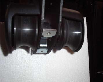
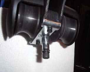
12 Issue Possible Cause What to Do Resistance is too high (unit is difficult to pedal on lowest resistance setting). Pedal arm/top of adjustable link assembly is assembled improperly; the two actuator bushings and nylock nuts may be improperly seated into the pedal arm clevis. Loosen the two nylock nuts on the pedal arm at the top of the adjustable link assembly (Figure 2.9). Re-tighten the pedal arm bolt. Make sure it is properly seated and snug but not overly tight. Clevis bushing at the pedal arm is too tight. The white plastic actuator nut is held in place at the pedal arm by the clevis bushing (Figures 2.9 and 2.10). Remove the nylock nut and two hex-head screws. Use while lithium grease to lubricate the actuator nut posts where the clevis bushing slides. Move the clevis bushing to ensure that it slides freely. Replace and tighten the nylock nut. Drive belt tension is too high. Twist the drive belt with your fingers; it should twist approximately 45º or less. Locate the three set screws on the plate attaching the belt tensioner assembly to the generating brake assembly (Figure 2.11). Record their current positions by marking the plate. Loosen the adjustor nut at the bottom of the J-hook bolt, then loosen the three set screws, allowing the plate to rotate. To loosen the tension, rotate the plate counter-clockwise slightly, then retighten the set screws and the adjustor nut. Recheck the drive belt tension as above, making sure that slippage does not occur between the belt and the pulley while pedaling the unit and when changing direction while pedaling. 12 Octane Fitness Confidential


13 Nylock nut Actuator Nut Actuator Shaft Clevis bushing Clevis Bearings Figure 2.9 Figure 2.10 Hook Bolt Screws Adjustor Nut Belt Tensioner Figure Octane Fitness Confidential
14 Issue Possible Cause What to Do Belt tracking is off center. Resistance is too high (unit is difficult to pedal on lowest resistance setting). The drive belt should ride in the center, not shifted to the right or left (Figure 2.12). If it is off center, you may feel some added resistance and will hear a rubbing or swishing noise. No resistance change. Console is not properly connected. Inspect the belt tensioner (Figure 2.13). If it is bent, causing the belt to be off center, replace it following the directions in Section III. Remove the four (4) screws securing the console to the console upright tube. Faulty console key. Faulty console. Faulty wiring (cable assembly). Unplug and re-plug the connections into the console, listening for the clicks to ensure good connections (Figure 2.14). Also verify that the ground connections are secure. While pedaling the machine, use the Level +/- keys to increase and then decrease the resistance. If you are able to change resistance in one direction but not the other, you may have a faulty key on the console. Replace the keypad overlay according to the directions in Section III. If the resistance still does not change when you change levels on the console, unplug the cable and plug it into a new console. If this resolves the issue, replace the old console with the new one according to the directions in Section III. While pedaling the machine, use the Level +/- keys to increase and decrease the resistance. If the generator brake does not respond, replace the cable assembly according to the directions in Section III. Faulty keypad (keys are sticking or not responding). Faulty control board. Plug the cables in and verify that all functions are working. Replace the keypad overlay according to the directions in Section III. If the issue persists after all other components have been verified, replace the control board according to the directions in Section III. 14 Octane Fitness Confidential


15 Hook Bolt Screws Adjustor Nut Figure 2.12 Belt Tensioner Figure 2.13 Connections to check Ground (2) Figure Octane Fitness Confidential
16 2.3 Console Issues The General Service Information Manual provides directions for removing shrouds to access the inside of the unit. Issue Possible Cause What to Do Machine enters pause mode while in use. Speed sensors are improperly connected or aligned. The Pro4500 has two speed sensors to detect forward and reverse motion. The speed sensors must be properly aligned with the magnet (Figures 2.15 and 2.16). Disconnect and reconnect each speed sensor at the cable harness to ensure a good connection. Check the position and alignment of the speed sensors and magnet, as shown in Figure Magnet is not magnetic or is missing. To adjust the position of a speed sensor, loosen the set screw and gently slide the speed sensor wire harness so that it is approximately 1/8-inch from the magnet, and level, then re-tighten the screw. Verify that the magnet is magnetic by touching it with a steel screwdriver. If it is not, contact Octane Fitness Customer Service for assistance. Console-entered program parameters (weight, level, etc.) are not being retained in memory. Faulty console, speed sensors, or upper wire harness. Faulty software. Verify that the magnet is installed in the drive pulley. If it is missing, contact Octane Fitness Customer Service for assistance. If the speed sensors and magnet are properly installed, positioned, and aligned, you will need to test for faulty components. Refer to Section III for instructions on replacing a console, speed sensor, or upper wire harness. Unplug the machine, then remove the four (4) screws securing the console to the console upright tube. Unplug the cables and plug them into a new console, listening for clicks to ensure good connections. Plug in the unit and check. If this resolves the issue, update the software according to the directions in Section III. 16 Octane Fitness Confidential


17 Front Sensor Figure 2.15 Back Sensor Speed Sensors Figure 2.16 Magnet 1/8 Approx. Speed Sensor Figure Octane Fitness Confidential
18 Issue Possible Cause What to Do Stride motor plug issues. Err2 (left) or Err3 (right) is displayed on the console. Locate the Smart Drive board on the right shroud mounting tube attached to the main upright tube (Figure 2.18). Unplug the Left (black) and Right (white) stride motor plugs from the Smart Drive board and reverse their positions, plugging the black plug into the white socket and the white plug into the black socket (Figure 2.19). For additional information about this procedure, refer to the Service Bulletin section in the General Service Information Manual. Plug in the unit. After the motors stop moving (8 to 15 seconds), unplug the unit again. Ground yourself before touching the circuit board. Unplug the stride motor plugs from the Smart Drive board and plug each one back into its default socket: Left (black) plug into the black socket and Right (white) plug into the white socket (Figure 2.19). Press the Pause/Clear button several times until Octane Fitness scrolls across the display matrix. Faulty stride motor. If the stride motor (left or right) causing the error is unresponsive (Err2 or Err3 is still displayed), it should be replaced following the directions in Section III. If a motor is completely unresponsive when you reverse the plug-ins as described above, you will need to replace the adjustable link assembly according to the directions in Section III. Faulty power supply. If the console flickers or is dimming just prior to the Err2 or Err3, replace the power supply and test. 18 Octane Fitness Confidential
 Figure 2.18 Left Stride Motor Plug Right Stride Motor Plug Speed Sensor Plug Power Plug Wire Harness Plug 19 Figure 2.")
19 Magnetic Brake/ Flywheel Upper & Lower Wiring Harnesses Smart Drive Board Brake Control Board Adjustable Link Assembly with Stride Motor Speed Sensors (rear sensor hidden by crank arm) Figure 2.18 Left Stride Motor Plug Right Stride Motor Plug Speed Sensor Plug Power Plug Wire Harness Plug 19 Figure Octane Fitness Confidential
20 Issue Possible Cause What to Do Faulty limit switch assembly Unplug the unit. on stride motor. Err6 and Err7 apply to the left stride motor; Err8 and Err9 apply to the right stride motor. Err6, Err7, Err8, or Err9 is displayed on the console, indicating limit switch issues. If the unit is new (that is, just out of the box), unplug and re-plug the limit switch assembly at the indicated stride motor (Figure 2.20) to ensure a good connection. Err11 is displayed on the console, indicating a communications issue. Faulty wiring harness. If the unit is not new and has previously been working without displaying these errors, check the plug-in for the limit switch assembly (Figure 2.20). If it is connected, disconnect it and plug in a new limit switch and test. If the error is resolved, complete the installation of the new limit switch according to the directions in Section III. Unplug the machine. Unplug and re-plug all connections between the Smart Drive and brake control boards and wiring harnesses (Figure 2.21). Console buttons are not responding or are sticking. Faulty console key. If the issue is not resolved, you will need to replace the wiring harness according to the directions in Section III. Replace the keypad overlay according to the directions in Section III. 20 Octane Fitness Confidential Pro
21 Actuator Shaft Actuator Motor Actuator Nut Clevis Bushing Actuator Shaft Retaining Bracket Nylock Nut Limit Switch Assembly Figure 2.20 Brake Connection Smart Drive Board Connections Figure Octane Fitness Pro4500 Confidential 2.3
22 2.4 Noise Issues The General Service Information Manual provides directions for removing shrouds to access the inside of the unit. Issue Possible Cause What to Do Rubbing roller wheels. Machine produces squeaking noise from pedal/rail area when in use. Wipe down the chrome rails with a dry rag. Apply a thin coat of white lithium grease along all four rails. Do not use WD-40 or silicone spray. With a clean rag or paper towel, work the grease down the chrome rails, covering the rails with a small amount of lubricant. Remove excess grease with a dry rag; only a very thin film should remain. Pedal the unit for a few minutes, then once again wipe off the chrome rails to remove any excess grease. Machine produces squeaking noise from within shrouds when in use. Misaligned rails or pedal arm. Actuator nut is too big or broken. If squeaking persists, replace the roller wheels according to the directions in Section III. Verify all wheels make contact with rails along the length of the rail at wheel level. If there is a gap between the wheel and rail you may need to replace the pedal arm or rails according to the directions in Section III. Remove the nylock nut and hex-head screws and inspect the actuator nut (Figures 2.22 and 2.23); if it is broken, replace it according to the directions in Section III. Use while lithium grease to lubricate the actuator nut posts where the clevis bushing slides. Machine produces scraping sound when in use. Hanging wires on links. Move the clevis bushing to ensure that it slides freely. Replace and tighten the nylock nut. Identify and secure any dangling or rubbing wires. Use zip-ties to gently tie the cables to the frame. Be careful not to tie the wires too tightly as ties that are too tight can damage the wires and interrupt the cable signals. 22 Octane Fitness Confidential
23 Actuator Shaft Actuator Motor Actuator Nut Clevis Bushing Actuator Shaft Retaining Bracket Nylock Nut Limit Switch Assembly Figure 2.22 Actuator Nut Actuator Shaft Clevis Bearings Figure 2.23 *WARNING: LINKAGES PRESENT NUMEROUS PINCH POINTS. USE CAUTION TO AVOID INJURY Octane Fitness Confidential
24 Issue Possible Cause What to Do Belt tracking is off center. Machine produces scraping sound when in use. The drive belt should ride in the center, not shifted to the right or left. If it is off center, you may feel some added resistance and will hear a rubbing or swishing noise. Pedal arm rubbing against rocker arm. Loose screws on stability links. Inspect the belt tensioner, shown in Figure If it is bent, causing the belt to be off center, replace it following the directions in Section III. If the scraping noise is metallic, inspect the space between the pedal arm and the rocker arm on each side of the machine while moving the pedals. This can be viewed through the slots in the back shroud. You may see where paint has been rubbed off of the arms. This inspection may need to be performed with a user on the pedal, as load on the pedal may cause contact between the links. Check and tighten the four socket head screws (17mm) attaching the stability links to the frame (Figure 2.25). Try the machine at slow and fast pace, forward and backward to see if the noise is still present. If the noise is still present, check the 2- pivot links and the adjustable link assembly for looseness and side-to-side motion (Figure 2.25). A slight side-to-side motion is normal at the rocker arm and 2-pivot link connection. No side-to-side motion should be seen in the adjustable link assembly. Section III provides directions for replacing links if necessary. 24 Octane Fitness Confidential
25 Hook Bolt Screws Adjustor Nut Belt Tensioner Figure 2.24 Adjustable Link Assembly with Stride Motor 2-Pivot Link Stability Link Screws to Check (2 on each side) Figure Octane Fitness Confidential
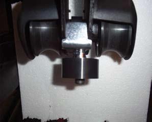
26 Issue Possible Cause What to Do Cracked or broken wheel. Machine produces a grinding sound from the wheel area when in use. Machine produces a popping or grinding sound from under the shrouds when in use. Machine produces clunking noise when in use. Broken bearing or generator brake/flywheel assembly. Loose links, pivots, or rocker arms. Inspect the roller wheels. If cracked or broken, replace according to the directions in Section III. Inspect the magnetic brake/flywheel by the pulley. If the bearing is cracked or broken, it will be popped out on the side opposite the pulley (Figure 2.26) If so, replace the brake assembly following the directions in Section III. Check the rails, wheels, and wheel covers to ensure that they are not rubbing against each other or against the back shroud. Open the top cover and using the moving handlebars to slowly move the machine through the full range of motion. This will help you determine if there is anything hitting and/or clunking, such as the wire harness rubbing against another part. Check to make sure all pivot joints on both sides of the machine are tight (Figure 2.27). Check and tighten the four socket head screws attaching the stability links to the frame and the four bolts attaching the crank shaft plate to the large drive pulley (Figure 2.28). Try the machine at slow and fast pace, forward and backward to see if the noise is still present. Check the 2-pivot links and the adjustable link assembly for looseness and side-toside motion (Figure 2.28). A slight sideto-side motion is normal at the rocker arm and 2-pivot link connection. No side-to-side motion should be seen in the adjustable link assembly. Section III provides directions for replacing links if necessary. If the noise persists, detach the crank arm from the middle adjustable link bolt on both right and left sides. Move the drive pulley; if the noise persists you may need to replace the pivot shaft and/or crank shaft assembly. Refer to Section III for directions. 26 Octane Fitness Confidential

27 Figure 2.26 Adjustable Link Assembly with Stride Motor 2-Pivot Link Pivots to check, both Right and Left sides, inside and outside Figure 2.27 Stability Link Screws to Check (2 on each side) Figure Octane Fitness Confidential
28 Issue Possible Cause What to Do Motor sounds like it is laboring, running very hard or very slow. Motor sounds like it is laboring, running very hard or very slow. Inadequate or faulty power supply. Tension or stress on the actuator shaft or actuator nut. Replace power supply with a new 6.25 amp power supply and test. The white plastic actuator nut is held in place at the pedal arm by the clevis bushing (Figures 2.29 and 2.30). Unplug the unit and remove the nylock nut and hex-head screws securing the clevis bushing. Use white lithium grease to lubricate the actuator nut posts where the clevis bushing slides. Move the clevis bushing to ensure that it slides freely. Actuator shaft threads are not properly lubricated. Broken actuator shaft retaining bracket. Faulty stride motor. Replace and tighten the nylock nut and hex-head screws. Apply white lithium grease to the threaded actuator shaft (Figure 2.30), including the top, middle, and just below the retaining bracket. Inspect the black retaining bracket to see if it is cracked or broken (Figure 2.29). If it is, replace it according to the directions in Section III. If a motor is unresponsive or continues to labor, you will need to replace the adjustable link assembly according to the directions in Section III. 28 Octane Fitness Confidential
29 Actuator Motor Nylock Actuator Nut Clevis Bushing Actuator Shaft Actuator Shaft Retaining Bracket Nylock Nut Limit Switch Assembly Figure 2.29 Actuator Nut Actuator Shaft Clevis Bearings Figure Octane Fitness Confidential
30 2.5 Heart Rate Monitoring Issues Issue Possible Cause What to Do Erratic or illogical heart rate reading from the chest strap (too high or too low). Erratic or illogical heart rate reading from the handgrips (too high or too low). Improper usage of optional chest strap. Interference with other machines or devices. Faulty handgrips. The chest strap must be worn snugly against bare skin at the bottom of the pectoral muscles with the Octane Fitness logo right side up and facing away from the body. For best contact, the transmitter should be moistened. The chest strap may need to be moved to the right or left, up or down on the chest to secure a reading. Try the chest strap on a different user. Some individuals are unable to use a chest strap due to different body composition/ chemistry. If the user tries these adjustments and no heart rate reading appears, replace the chest strap battery (CR V). If the user tries these adjustments and no heart rate reading appears, you will need to provide a new chest strap. Fluorescent lights and electronic devices such as televisions, personal stereos, cordless or wireless telephones, stopwatches, wireless computers/internet, PDAs, or other exercise machines may interfere with the heart rate transmission. Turn off other devices to isolate and eliminate the interference. The digital contact heart rate sensors on the stationary handlebars must be grasped so that the contact sensor portion of the grip rests in the palm of the hand. The grips must be grasped firmly and the hands kept steady and in place. Use a screwdriver to remove the endcaps from the tops of the stationary handlebars (Figure 2.31). Inspect the wires inside each handgrip (Figure 2.32). Verify that no wires are loose or have been pinched or crimped. If any damaged wires are noted, replace the handgrips according to the directions in Section III. Remove the four (4) screws securing the console to the console upright tube. Verify that the heart rate sensor cables are properly connected to the heart rate sensor board. Unplug and reconnect both cables, listening for clicks to ensure good connections (Figure 2.33). Check the console ground connection by loosening and retightening it. You may need to scrape off a bit of paint to ensure good ground connection. If the issue is still present, replace the handgrips according to the directions in Section III. 30 Octane Fitness Confidential
 screws securing the console to the console upright tube. Verify that the heart rate sensor cables are properly connected to the heart rate sensor board.")

31 Issue Possible Cause What to Do Erratic or illogical heart rate reading, or NO HR message from both the chest strap and the handgrips. Faulty heart rate sensor cable in the console, or faulty console. Remove the four (4) screws securing the console to the console upright tube. Verify that the heart rate sensor cables are properly connected to the heart rate sensor board. Unplug and reconnect both cables, listening for clicks to ensure good connections (Figure 2.33). If heart rate issues still exist, unplug the cable and plug it into a new console, listening for the click to ensure a good connection. Plug in the unit and check. If this resolves the issue, replace the old console with the new one according to the directions in Section III. Figure 2.31 Figure 2.32 Heart Rate Cable Connections 31 Figure Octane Fitness Confidential
 Phillips screws and remove the plastic wheel cover. 3.")
32 SECTION III: 3.1 Roller Wheel Replacement Part Replacement & Adjustment Procedures 1. Verify that you have the correct wheels available. The wheels for the Pro4500 are a deep cut style (Figure 3.1). Contact Octane Fitness Customer Service if you need assistance identifying the proper wheels. 2. Remove two (2) Phillips screws and remove the plastic wheel cover. 3. Use a 6mm hex key to remove the button-head cap screw and the washer that holds the wheel on the axle. This screw may be very tight; use a pipe or a long breaker bar and a hex driver socket if you need additional leverage. 4. Remove the wheel assembly. If the wheel is stuck, you may need to pry it off using a large-blade flat screwdriver or a small pry bar. 5. Install the new wheel on the axle. If necessary, tap the wheel lightly with a rubber or hard plastic mallet to ensure that it is seated properly. Be careful not to damage the bearings. 6. Install the washer and button-head cap screw and tighten with the 6mm hex key. 7. Replace the plastic wheel cover and secure it with the two Phillips screws. 8. Wipe down the chrome rails with a dry rag. You may apply a thin coat of white lithium grease to all four rails only. Do not apply grease to the wheels. Do not use WD-40 or a silicone spray. With a clean rag or paper towel, work the grease down the rails, covering the rails with a small amount of lubricant. Remove excess grease with a dry rag; you should be able to feel the grease but not see it. 9. Power on the unit and pedal for several minutes to test, then once again wipe the rails with a clean dry rag to remove excess grease. 32 Octane Fitness Confidential Figure

 bolts located near the rear support, three on each pair of rails (Figure 3.3). 6. Remove the old rails and position the new rails. 7.")
33 3.2 Rails Replacement 1. Unplug the unit to avoid cord damage and remove the top, left, and right shrouds, following the directions in the General Service Information Manual. 2. Remove the pedal arms. 3. Loosen and lift the back shroud until it clears the lower frame, and lay the back shroud on the pedals. 4 Use an 8mm hex key to remove the four (4) screws at the top of the rail assembly, two on each set of rails (Figure 3.2). These may be very tight; you may need to use an extender to loosen them. 5. Use a 5mm hex key to remove the six (6) bolts located near the rear support, three on each pair of rails (Figure 3.3). 6. Remove the old rails and position the new rails. 7. Reuse or replace the rubber gaskets that fit between the rails and rear support. 8. Insert and tighten the rear bolts using the 5mm hex key. 9. Insert and tighten the screws at the front of the rail assembly using the 8mm hex key. 10. Wipe down the chrome rails with a dry rag. You may apply a thin coat of white lithium grease to all four rails only. Do not apply grease to the wheels. Do not use WD-40 or a silicone spray. With a clean rag or paper towel, work the grease down the rails, covering the rails with a small amount of lubricant. Remove excess grease with a dry rag; you should be able to feel the grease but not see it. 11. Reattach the pedal arms. 12. Plug in the unit and pedal for several minutes to test, then once again wipe the rails with a clean dry rag to remove excess grease. 13. Reposition the back shroud; check to make sure the inlet plug did not unplug from the cable assembly or get pinched. Secure the back shroud with its four screws. Replace the right, left, and top shrouds and secure. Figure 3.2 Figure Octane Fitness Confidential
34 3.3 Side Roller Kit Replacement or Installation For all installations and replacements:: 1. Unplug the unit. Follow the directions below for both pedal arms (left and right). 2. Raise the pedal and prop it up securely (Figure 3.4. If replacing an existing side roller wheel only: 4. Remove the old wheel from the threaded hole and install the new wheel in the threaded hole so that the wheel is centered between the two roller wheels (Figure 3.5). If replacing an existing side roller wheel and brackets: 4. Remove two (2) hex bolts securing the brackets to the pedal arm and remove brackets. 5. Install and hold the U-bracket on the axle. (Figure 3.5). 6. Install and secure the axle bracket (with roller removed) with two (2) hex bolts. Make sure the bracket tab faces the rear (Figure 3.6). Use Loctite or similar liquid thread locker on bolts. 6. Install the new wheel in the threaded hole so that the wheel is centered between the two roller wheels (Figure 3.7). If installing a new side roller wheel assembly: 4. Install and hold the U-bracket on the axle. (Figure 3.7). 5. Install and secure the axle bracket (with roller removed) with two (2) hex bolts. Make sure the bracket tab faces the rear (Figure 3.6). Use Loctite or similar liquid thread locker on bolts. 6. Install the wheel in the threaded hole so that the wheel is centered between the two roller wheels (Figure 3.5). After any replacement or installation:: Lower the pedal arm. Verify that the wheel is close to the outside rail (Figure 3.8). Wipe down the chrome rails with a dry rag. You may apply a thin coat of white lithium grease to all four rails only. Do not apply grease to the wheels. Do not use WD-40 or a silicone spray. With a clean rag or paper towel, work the grease down the rails, covering the rails with a small amount of lubricant. Remove excess grease with a dry rag; you should be able to feel the grease but not see it. Plug in the unit and pedal for several minutes to test, then once again wipe the rails with a clean dry rag to remove excess grease. 34 Octane Fitness Confidential


35 U-Bracket Figure 3.4 Figure 3.5 Bracket Tab Figure 3.6 Figure 3.7 Figure Octane Fitness Confidential
. 2. Use an hex key to remove the two (2) hex-head screws from the clevis bushings on each side of pedal arm. 3.")
36 3.4 Pedal Arm Replacement 1. Unplug the unit, then loosen and move the top shroud so that you can see where the pedal arm is attached to the top of the adjustable link assembly. Follow the directions below for both pedal arms (left and right). 2. Use an hex key to remove the two (2) hex-head screws from the clevis bushings on each side of pedal arm. 3. Using a 13mm wrench, loosen the two (2) actuator nylock nuts that hold the pedal arm in place, remove the two bushings, and push the pedal arm down the rails so it is out of the way. (Figure 3.9). 4. Remove the old pedal arm and slide the new one into position. Pedal arms are side-specific and labeled L (left) and R (right). 5. Install nylock nuts and hex-head screws and tighten. 6. Move the pedal arms forward and backward a few times; they should feel tight with no side-to-side motion. Actuator Nut Actuator Shaft Smart Drive Board Actuator Nylock Nut & Bushings Zip Tie Crank Arm Stride Motor Clevis Bearings Figure 3.9 Adjustable Link Assembly with Stride Motor 18mm Bolt Stability Link Center Bolt 2-Pivot Link Pedal Arm Rocker Arm Figure Octane Fitness Confidential
37 3.5 Adjustable Link Assembly Replacement 1. Unplug the unit, loosen the top shroud and remove the left shroud. If you are replacing the right stride motor, also remove the right shroud. 2. Unplug the motor from the Smart Drive board. The Left motor is the black plug, the Right motor is the white plug (Figure 3.11). 3. Use a hex key to remove the two (2) hex-head screws from the actuator nut bushings on each side of pedal arm. 4. Using a 13mm wrench, loosen the two (2) actuator nylock nuts that hold the pedal arm in place, remove the two bushings, and push the pedal arm down the rails so it is out of the way. (Figure 3.10). 5. Using a 19mm wrench, loosen and remove the nylock nut securing the large center bolt connecting the 2-pivot link and the crank arm. To avoid injury, hold the rocker arm with one hand, then remove the center bolt, and lay the stride motor down on the ground. 6. Using an 18mm wrench, loosen the bolt connecting the stability link to the stride motor assembly and remove the stride motor assembly from the stability link. 7. Attach the new stride motor assembly to the stability link using an 18mm wrench. 8. Lift the stride motor assembly on the stability link up into position, reinsert the center bolt into the 2-pivot link and crank arm, and use a 19mm wrench to secure it with the nylock nut. 9. Push the pedal arm up the rails into position, replace the two bushings, and use a 13mm wrench to retighten the two (2) actuator nylock nuts. 10. Replace and tighten the two (2) hex-head screws that secure the actuator nut bushings on each side of the pedal arm. 11. Plug the stride motor into its proper plug on the Smart Drive board (Left is black, Right is white), turn on the unit, and test for proper functioning. 12. Zip-tie the wires down so that they don t get tangled. 13. Replace the right shroud (if it was removed), then the left shroud, and reposition the top shroud; secure with shroud screws. Left Stride Motor Plug Right Stride Motor Plug Speed Sensor Plug Power Plug Wire Harness Plug Octane Fitness Confidential Figure 3.11
38 3.6 Stride Motor Replacement and Calibration 1. Unplug the unit, loosen the top shroud and remove the left shroud. If you are replacing the right stride motor, also remove the right shroud. Refer to Figure 3.12 as you proceed. 2. Unplug the motor from the Smart Drive board. The Left motor is the black plug, the Right motor is the white plug. 3. Unplug the motor from the limit switch assembly. 4. Remove the two (2) socket-head cap screws holding the retainer bracket to the pivot link. 5. Remove the two (2) socket-head cap screws holding the motor to the pivot link. 6. Cut the six (6) zip ties securing the motor and its cable, and remove the old stride motor. 7. Position the new stride motor. The motor slot needs to slip into the threaded shaft slot. Secure the motor with a zip tie. 8. Route the cable and secure it with zip ties (5 in total). 9. Replace and tighten the two (2) socket-head cap screws holding the motor to the pivot link. 10. Replace and tighten the two (2) socket-head cap screws holding the retainer bracket to the pivot link. 11. Plug the stride motor into its proper plug on the Smart Drive board (Left is black, Right is white. 12. Verify that both stride motor actuator nuts are in the top or bottom position or close to one another (Figure 3.13). If they are properly aligned, turn on the unit, and test for proper functioning. If the actuator nuts are not properly aligned (that is, one is at the top position and one at the bottom), the following steps may need to be taken to recalibrate the stride motors and prevent an error message from occurring: 1. Switch the Stride Motor Plugs on the control board. 2. Plug machine in. Watch the movement of the stride motor actuator nut that is moving. Unplug the machine when the actuator nut is close to or at the same position as the other one (Figure 3.13). 3. Switch the plugs back to the original location. Plug in machine. 4. Both motors should begin moving then stop in the same position. Motors are now calibrated. 5. Pedal the unit for a few minutes to verify proper functioning. 38 Octane Fitness Confidential

 39 1-800-628-2634 Octane")
39 Actuator Shaft Actuator Motor Actuator Nut Clevis Bushing Actuator Shaft Retaining Bracket Nylock Nut Limit Switch Assembly Figure 3.12 Correct alignment (calibrated) Figure 3.13 Incorrect alignment (not calibrated) Octane Fitness Confidential
. 2.")
40 3.7 Actuator Nut Replacement Note: Left and Right actuator nuts are different; make sure you have the correct part before beginning installation. 1. Unplug the unit and remove the shrouds to access the inside. Follow the directions below for each side of the machine (left and right adjustable link assemblies). 2. Remove the two (2) nylock nuts and two (2) hex-head screws that attach the pedal arm to the adjustable link assembly. 3. Remove the two hex-head screws holding the retainer bracket to the pivot link (Figure 3.14). 4. Remove the two (2) hex-head screws holding the motor to the pivot link. 5. Pull the actuator motor away from the actuator shaft. 6. Slide the shaft down and away from the 3-pivot link, and remove the actuator shaft bracket. Use caution as the thrust bearing and washer may separate as you pull the shaft out of the upper bushing (Figure 3.15). 7. Thread the old actuator nut off the bottom the threaded actuator shaft. 8. Thread the new actuator nut onto the shaft. 9. Slide the shaft up and into the 3-pivot link and push the actuator shaft toward the actuator motor. 10. Replace and tighten the 2 (2) hex-head screws holding the motor to the pivot link. 11. Replace and tighten the two (2) hex-head screws holding the retainer bracket to the pivot link. 12. Inspect the crank arm alignment to verify that it is flush with the crank shaft. 13. Replace and tighten the two (2) nylock nuts and two (2) hex-head screws that attach the pedal arm to the adjustable link assembly. 14. Plug in the unit and test. Smart Drive Board Actuator Nylock Nut & Bushings Actuator shaft Crank Arm Zip Tie Stride Motor Caution: thrust bearing and washer may separate during removal Adjustable Link Assembly with Stride Motor 18mm Bolt Stability Link Center Bolt 2-Pivot Link Pedal Arm Rocker Arm Figure Figure 3.14 Octane Fitness Confidential
 hex-head screws holding the retainer bracket to the pivot link (Figure 3.16). 4. Remove the two (2) hex-head screws holding the motor to the pivot link. 5.")
41 3.8 Actuator Shaft Retaining Bracket Replacement 1. Use the console keypad to extend the stride length to 23, the top of the actuator shaft. 2. Unplug the unit and remove the shrouds to access the inside. 3. Remove the two (2) hex-head screws holding the retainer bracket to the pivot link (Figure 3.16). 4. Remove the two (2) hex-head screws holding the motor to the pivot link. 5. Pull the actuator motor away from the actuator shaft. 6. Slide the shaft down and away from the 3-pivot link, and remove the actuator shaft retaining bracket. Use caution as the thrust bearing and washer may separate as you pull the shaft out of the upper bushing (Figure 3.15). 7. Install the new bracket onto the shaft. 8. Slide the shaft up and into the 3-pivot link and push the actuator shaft toward the actuator motor. 9. Replace and tighten the two (2) hex-head screws holding the motor to the pivot link. 10. Replace and tighten the two (2) hex-head screws holding the retainer bracket to the pivot link. 10. Plug in the unit and test. Actuator Motor Actuator Nut Clevis Bushing Actuator Shaft Actuator Shaft Retaining Bracket Nylock Nut Limit Switch Assembly Figure Octane Fitness Confidential
42 3.9 Belt Tensioner Replacement and Adjustment 1. Unplug the unit and remove the shrouds to access the inside. Figure 3.17 shows the belt tensioner assembly. 2. Locate the three (3) hex screws that hold the belt tensioner assembly to the generating brake assembly. Note the position of each screw by putting a mark on the plate. 3. Use a 13mm wrench to remove the adjustor nut and the J-hook bolt. 4. Use a 4mm hex wrench to remove the three hex screws that hold the belt tensioner to the frame. 5. Remove the belt tensioner and replace it with a new one. 6. Replace the three (3) hex screws that hold the belt tensioner to the frame and rotate the plate so that each screw is aligned with its mark on the plate. Tighten the three screws. 7. Replace the J-hook bolt and tighten the adjustor nut. 8. Twist the drive belt with your fingers. It should move approximately 45º or less. Test by pedaling the machine. Slippage should not occur between the belt and the pulley while pedaling the unit and when changing direction while pedaling. If the belt is too tight or too loose, loosen the adjustor nut and the hex screws and rotate the plate until the proper tension is found; tighten and test. Hook Bolt Screws Adjustor Nut Belt Tensioner Figure Octane Fitness Confidential
. Cut the zip ties securing the speed sensor wires to the frame. 4.")

43 3.10 Speed Sensor Replacement 1. Unplug the unit and remove the shrouds to access the inside. 2. Unplug the speed sensor connector from the Smart Drive board (Figure 3.18). 3 Locate the two speed sensors mounted to the frame (Figure 3.19). Cut the zip ties securing the speed sensor wires to the frame. 4. Use a Phillips screwdriver to unscrew the original sensor from the frame. Rotate the speed sensor and slide it off the screw shaft. 5. Speed sensors are labeled F (front) and B (back). Select the proper speed sensor and attach it to the frame with the screw, making sure that the sensor is seated all the way against the screw shaft.. 6. Level and align the sensor with the pulley magnet. Leave a gap of approximately 1/8-inch between the sensor and the magnet, taking care that no physical contact occurs (Figure 3.20). Tighten screw to secure position. 7. Thread the speed sensor wire along the frame up to the Smart Drive board, securing them to the frame with zip ties. 8. Plug the new sensor connector into the Smart Drive board and power on the unit to test. Left Stride Motor Plug Right Stride Motor Plug Speed Sensor Plug Figure 3.18 Power Plug Magnet Figure /8 Approx. Speed Sensor Figure Octane Fitness Confidential
44 3.11 Brake Assembly/Pulley Replacement *CAUTION: THIS ASSEMBLY IS VERY HEAVY. USE CAUTION TO AVOID INJURY. BE PREPARED TO HOLD AND LOWER IT GENTLY UPON REMOVING THE FRAME BOLTS. 1. Remove all shrouds to access the inside of the unit. 2. Disconnect the power cable from the generating brake (Figure 3.21). 3. Locate the three (3) hex screws that hold the belt tensioner assembly to the generating brake assembly (Figure 3.22). Note the position of each screw by putting a mark on the belt plate. 4. Use a 13mm wrench to remove the adjustor nut and the J-hook bolt. 5. Use a 4mm hex wrench to remove the three hex screws that hold the belt tensioner assembly to the frame and remove the assembly. 6. From the left side of the machine, use a 5mm hex wrench to remove the two bolts securing the brake assembly to the frame (Figure 3.23). 7. From the right side of the machine, use a 5mm hex wrench to remove the two bolts securing the brake assembly to the frame (Figure 3.22). This assembly is very heavy; if possible, one person should hold the assembly while another removes the bolts. 8. Remove the old assembly and replace it with a new one; insert the two bolts into the frame on the right side of the machine and use a 5mm hex wrench to tighten. 9. Insert the two bolts into the frame on the left side of the machine and use a 5mm hex wrench to tighten. 10. Position the belt tensioner assembly and replace the three (3) hex screws that hold the assembly to the frame but do not tighten the screws. 11. Rotate the plate so that each screw is aligned with its mark on the belt plate. Tighten the three screws with a 4mm hex wrench. 12. Replace the J-hook bolt and tighten the adjustor nut with a 13mm wrench. 13. Twist the drive belt with your fingers. It should move approximately 45º or less. Test by pedaling the machine. Slippage should not occur between the belt and the pulley while pedaling the unit and when changing direction while pedaling. If the belt is too tight or too loose, loosen the adjustor nut and the hex screws and rotate the plate until the proper tension is found; tighten and test Reconnect the power cable to the generating brake. 15. Pedal the unit to test. 44 Octane Fitness Confidential

45 Wire Cage Power Connection Figure 3.21 Hook Bolt Left side Bolts to Remove Brake/Frame Bolts to Remove Screws Adjustor Nut Belt Tensioner Figure 3.22 Figure Octane Fitness Confidential
46 3.12 Upper and Lower Wire Harness Replacement 1. Unplug the unit and remove all shrouds. 2 Remove the four (4) Phillips screws securing the console to the mast assembly. 3. Unplug all connections from the back of the console. 4. Pull the upper wire harness down through the mast assembly and unplug it from the top of the frame (Figure 3.24). 5. Plug the new upper wire harness into the top of the frame and into the console, listening for the click to ensure a good connection. 6. Power on the machine and verify that the console is working. 7. Unplug the connectors from the back of the console. 8. Drop a string or a wire down through the mast assembly, tie it to the cable assembly, and thread the cable up through the mast (Figure 3.25). 9. Plug the new upper wire harness cables into the console, listening for the clicks to ensure good connections. 10. Secure the console to the upright mast with the four Phillips screws. 11. Plug in the unit and test. 12. If required, plug a new lower wire harness at the top of the frame where it connects with the upper harness (Figure 3.24), allowing the old lower wire harness to dangle (unplugged). 13. Using a screwdriver, remove the screw that secures the wire cage over the brake control board (Figure 3.26). 12. Unplug the old wire harness and plug in the new one at three connection points (Figure 3.26): Smart Drive board, brake control board, and communications port (not shown). 13. Plug in the unit and test. 14. Once the new lower wire harness is connected and tested, cut the zip ties and remove the old wire harness. 15. Use zip ties to secure the wiring new harness to the frame. 16. Replace all shrouds and secure with shroud screws. 46 Octane Fitness Confidential
 Figure 3.24 Figure 3.")

47 Connection from mast (console) Optional connection for LCD Kit Lower wire harness (splits to 3 cables) Figure 3.24 Figure 3.25 To Brake Control Board To Smart Drive Board Wire Cage To Communications Port at base Octane Fitness Confidential Figure 3.26
48 3.13 Pivot Shaft Replacement 1. Remove the shrouds to access the inside. Follow the directions below for each side of the machine (left and right pivot shafts). 2. Remove the two (2) bolts and washers that attach the rocker arm to the pivot shaft (Figure 3.27). 3. Remove the four (4) bolts that attach the moving handlebar to the pivot shaft (Figure 3.28). 4. Use an 8mm socket head wrench to remove the cap screws securing the pivot shaft (Figure 3.29). 5. Notice how the tabs are bent on the washer. Using a flathead screwdriver and a hammer, tap the bent tabs to straighten them. 6. Use a 32mm or 33mm wrench to remove the nut. Slide the shaft out. 7. Replace the tab washer, then slide the new shaft into the frame. The tab on the inside of the washer fits into the channel on the shaft. 8. Replace the nut and tighten using a channel lock or crescent wrench. 9. Remembering the way the tabs on the old washer were bent, fold two tabs of the washer inward and two tabs outward, 10. Re-install the moving handlebar and move it back and forth to determine the appropriate tightness for the pivot shaft. The handlebars should move freely but without lateral movement or wobble. 11. Tighten the two (2) caps screws in hex collar to lock it into place. 12. Use the two (2) bolts and washers to attach the rocker arm to the pivot shaft, tightening until the link is secure. 13. Replace the shrouds and shroud screws. 48 Octane Fitness Confidential


49 Smart Drive Board Magnetic Brake/ Flywheel Drive Pulley Crank Arm Belt Tensioner Adjustable Link Assembly with Stride Motor 2-Pivot Link Pedal Arm Stability Link Rocker Arm Figure 3.27 Figure 3.28 Figure Octane Fitness Confidential
50 3.14 Heart Rate Sensor Cable/Board Replacement 1. Remove the four (4) Phillips screws securing the console to the upright tube. 2. Unplug the cable assembly connector from the back of the console. 3. Remove the six (6) Phillips screws holding the two pieces of the console casing together and separate the console casing. 4. Unplug the heart rate cables from the console circuit board and remove it from the glue and tape that hold it to the console back. (Figure 3.30). 5. Plug a new heart rate sensor assembly into the console circuit board. 6. Place the two pieces of the console casing together, holding the circuit board in place. Plug the console cable into the console, listening for the click to ensure a good connection. 7. Carefully flip over the console casing and power on the machine. Put on a heart rate strap and verify that a heart rate reading is displayed on the console. 8. Separate the console pieces again and glue the new heart rate sensor assembly to the console, making sure the wires are properly positioned so they won t be pinched when the console pieces are pressed back together. 9. Place the console pieces together once more, making sure that the LEDs are aligned properly in the console windows, and secure the console casing with the six (6) Phillips screws, 10. Re-attach the console to the upright tube with the four (4) Phillips screws. Heart Rate Cable Connections Figure Octane Fitness Confidential


51 3.15 Digital Contact Heart Rate Sensor Replacement 1. Use a screwdriver to remove the end caps from the top of the handgrips on each side of the machine (Figure 3.31). Repeat the following steps for both the left and right handgrips. 2 Beginning at the top, carefully separate the two sides of the handgrip. You may need to use a flat screwdriver to lever the pieces apart. 3. Use tape to label the two heart rate connectors so that you know which one connects to each side of the handgrip (Figure 3.32). 4. Disconnect the two heart rate connectors and remove the old handgrips. 5. Position the new handgrip pieces and connect the two heart rate connectors to the appropriate connectors in the new handgrip. 6. Carefully snap the two sides of the handgrip together, avoiding pinching the wires 7. Replace the end cap. Figure 3.31 Figure Octane Fitness Confidential
 connections from the console and plug them into the new console, listening for the clicks to ensure good connections (Figure 3.33). 4.")
52 3.16 Console Replacement 1. Unplug the unit. 2 Remove the four (4) Phillips screws securing the console to the upright tube and detach the two (2) console ground connections. 3. Unplug the six (6) connections from the console and plug them into the new console, listening for the clicks to ensure good connections (Figure 3.33). 4. Power on the unit to verify the new console is working properly. 5. Reattach the two (2) console ground connections. 5. Re-attach the new console to the upright tube with the four (4) Phillips screws. Connections to check Ground (2) Figure Octane Fitness Confidential
 Phillips screws holding the two pieces of the console casing together and separate the console casing. 4. Unplug the main overlay cable from the console circuit board (Figure 3.34).")

53 3.17 Console Overlay Replacement 1. Unplug the unit, then remove the four (4) Phillips screws securing the console to the upright tube. 2. Unplug the cable connections from the back of the console. 3. Remove the six (6) Phillips screws holding the two pieces of the console casing together and separate the console casing. 4. Unplug the main overlay cable from the console circuit board (Figure 3.34). 5. Carefully peel the old overlay from the console keypad and pull the cable out of its slot in the console (Figures 3.35 and 3.36). Note: Console color on the Pro4500 is gray instead of black as shown in these photographs. 6. Make sure the area is free of dirt or dust, then feed the new overlay cable through its slot, but do not attach it to the console circuit board. 7. Carefully align the overlay on the keyboard so that you can feel the buttons beneath it and press it into place. 8. Attach the overlay cable to the console circuit board. 9. Place the two pieces of the console casing together, holding the circuit board in place and making sure that the LEDs are aligned properly in the console windows. 10. Plug the console cables into the console, listening for the click to ensure a good connection. 11. Pedal the unit and test to ensure proper functioning. 12. Secure the console casing with the six (6) Phillips screws, 13. Re-attach the console to the upright tube with the four (4) Phillips screws. Console Connection Figure 3.35 Figure 3.34 Figure Octane Fitness Confidential
 screws securing the console to the mast and tip the console forward to access the connections. 2.")
54 3.18 Software Update Software updates for your Octane Fitness elliptical cross trainer are installed using a small handheld device called a pocket programmer (Figure 3.37). To obtain a pocket programmer, contact Octane Fitness Customer Service. 1. Remove the four (4) screws securing the console to the mast and tip the console forward to access the connections. 2. Position the pocket programmer so that the red stripe on the ribbon cable is on the right (Figure 3.37). 3. Insert the 6-pin connector of the pocket programmer firmly into the 6-pin connector just above the ground connections on the back of the console (Figure 3.38). 4. The light on the pocket programmer will be yellow, indicating a proper connection (Figure 3.39). Press the button on the front of the pocket programmer to begin the software update. When the software update is complete, the light on the pocket programmer will be green. 5. Disconnect the pocket programmer from the back of the console. 6. Reposition the console on the mast and secure with the four (4) screws. 6-pin Connector Red line 54 Figure 3.37 Octane Fitness Confidential

 Figure 3.")

55 6-pin connector Figure 3.38 Ready (Yellow Light) Update Complete (Green Light) Figure Octane Fitness Confidential

56 3.19 Smart Drive Board Replacement 1. Unplug the unit, loosen and rotate the top shroud. 2 Use masking tape to mark each wire so you will remember where it goes, then unplug all the wires from the Smart Drive board. 3. Using needle nose pliers, squeeze the four (4) plastic mounts and pop the board off of the frame (Figure 3.40). 4. Install the new board on the plastic mount. Listen for the snap to verify that it is properly seated. 5. Plug all the wires into the correct spots on the new board and remove the tape markings. 6. Test for proper functioning. 7. Reposition the top shroud; secure with shroud screws. Smart Drive Board Plastic Mounts (4) Figure Octane Fitness Confidential

57 3.20 Brake Control Board Replacement 1. Loosen the top shroud and remove the left and right shrouds. 2 Using a screwdriver, remove the screw that secures the wire cage over the brake control board. 3. Use masking tape to mark each wire so you will remember where it goes, then unplug all the wires from the control board. 4. Using a screwdriver, disconnect the ground wire from the frame (Figure 3.41). 5. Using needle nose pliers, squeeze the four (4) plastic mounts and pop the board off of the frame (Figure 3.41). 5. Install the new board on the plastic mount. Listen for the snap to verify that it is properly seated. 7. Use a screwdriver to connect the ground wire to the frame. 6. Plug all the wires into the correct spots on the new board and remove the tape markings. 7. Pedal the unit to test for proper functioning. 8. Replace the right and left shrouds and reposition the top shroud; secure with shroud screws. Plastic Mounts (4) Figure Octane Fitness Confidential
. 3. Unplug the limit switch assembly from the motor (Figure 3.43). 4.")
, attach it to the motor assembly with the Phillips screws, and secure the cable with a zip-tie.. 6. Reconnect the limit switches to the motor 7.")
58 3.21 Limit Switch Assembly Replacement 1. Unplug the unit, loosen the top shroud and remove the left shroud. If you are replacing the right limit switch assembly, also remove the right shroud. 2 Unplug the motor from the Smart Drive board. The Left motor is the black plug, the Right motor is the white plug (Figure 3.42). 3. Unplug the limit switch assembly from the motor (Figure 3.43). 4. Using a Phillips screwdriver, remove the four (4) screws securing the limit switch unit to the motor assembly (Figure 3.44), cut the small zip-tie, and remove the limit switch unit. 5. Position the new limit switch unit (Figure 3.45), attach it to the motor assembly with the Phillips screws, and secure the cable with a zip-tie.. 6. Reconnect the limit switches to the motor 7. Reconnect the motor to the Smart Drive board. 8. Replace the right shroud (if it was removed), then the left shroud, and reposition the top shroud; secure with shroud screws. Left Stride Motor Plug Right Stride Motor Plug Actuator Shaft Actuator Nut Actuator Motor Clevis Bushing Speed Sensor Plug Wire Harness Plug Power Plug Actuator Shaft Retaining Bracket Nylock Nut Limit Switch Assembly Figure 3.42 Figure Figure 3.44 Figure 3.45 Octane Fitness Confidential
SX1000 Service Manual SALES: CUSTOMER SERVICE:
 SX1000 Service Manual SALES: 800-278-3933 CUSTOMER SERVICE: 800-745-1373 Revision: August 1999 Table of Contents Section Page I. Overview 2 II. Troubleshooting Tables 3 III. Maintenance Procedures Procedure
Preventative Maintenance and Diagnostics
 Preventative Maintenance and Diagnostics JUNE 2016 Please Read Before You Begin IMPORTANT Before working on any Octane Fitness product, please take the time to look through the product specific manuals.
Cybex Arc Trainer Owner s & Service Manual. 7 - Service
 7 - Service Table of Contents......... iii Warnings/Cautions All warnings and cautions listed in this chapter are as follows:! WARNING: All maintenance activities shall be performed by qualified personnel.
ISO1000R Service Manual SALES: CUSTOMER SERVICE:
 ISO1000R Service Manual SALES: 800-278-3933 CUSTOMER SERVICE: 800-745-1373 Revision: August 1999 Table of Contents Section Page I. Overview 2 II. Troubleshooting Tables 3 III. Maintenance Procedures Procedure
Troubleshooting Guide
 R2200/E3200 Brake Problems Tension works in reverse Press and hold start/stop button to reset and start magnet from correct starting position. Brake assembly is defective, replace brake. Console is defective,
RBK 815 Recumbent Cycle. RBK 815 Bicycle
 RBK 815 Bicycle Warning: This service manual is for use by Precor trained service providers only. If you are not a Precor Trained Servicer, you must not attempt to service any Precor Product; Call your
Section 5: Parts Replacement
 Section 5: Parts Replacement Should the STAR TRAC 4500 Treadmill experience a problem requiring replacement of a specific part, the following procedures will help and instruct in the replacement of major
Installation Manual TWM Performance Short Shifter Cobalt SS/SC, SS/TC, HHR SS, Ion Redline and Saab 9-3
 Page 1 Installation Manual TWM Performance Short Shifter Cobalt SS/SC, SS/TC, HHR SS, Ion Redline and Saab 9-3 Please Note: It is preferable to park on a flat surface, as you will have to engage and disengage
Pro Stepper Service Manual
 Pro Stepper Service Manual Table of Contents Table of Contents... 0 Display Panel... 1 Preventive Maintenance... 2 Preventive Maintenance Cont d... 3 Settings - Maintenance Mode... 4 Settings - Maintenance
T & T Service Manual
 T101-04 & T202-03 Service Manual 1 2 3 Contents CHAPTER 1: SERIAL NUMBER LOCATION... 6 CHAPTER 2: PREVENTATIVE MAINTENANCE 2.1 Preventative Maintenance... 8 2.2 Tension and Centering the Running Belt...
LS8.0T Service Manual
 LS8.0T Service Manual 1 TABLE OF CONTENTS CHAPTER 1: SERIAL NUMBER LOCATION...3 CHAPTER 2: PREVENTATIVE MAINTENANCE 2.1 Preventative Maintenance. 4 2.2 Tension and Centering the Running Belt....6 CHAPTER
Slingshot Rotrex Supercharger Kit
 Slingshot Rotrex Supercharger Kit This supercharger kit improves on the Slingshot by forcing more dense air into the engine and creating more power. Installation time of the supercharger depends on you
C554i Elliptical Fitness Crosstrainer
 C554i Elliptical Fitness Crosstrainer Warning: This service manual is for use by Precor trained service providers only. If you are not a Precor Trained Servicer, you must not attempt to service any Precor
Detroit Speed, Inc. Electric Headlight Door Kit Corvette P/N: &
 Detroit Speed, Inc. Electric Headlight Door Kit 1968-82 Corvette P/N: 122006 & 122007 The Detroit Speed Inc. Electric Headlight Door Kit replaces the stock vacuum actuated system on all 1968-82 Corvettes.
Installation Manual TWM Performance Short Shifter Subaru STi 2008+
 - 1 - Installation Manual TWM Performance Short Shifter Subaru STi 2008+ Please Note: It is preferable to park on a flat surface, as you will have to engage and disengage the hand brake and shift from
TC1000 Service Manual SALES: CUSTOMER SERVICE:
 TC1000 Service Manual SALES: 800-278-3933 CUSTOMER SERVICE: 800-745-1373 Table of Contents Section Page I. Overview 2 II. Troubleshooting Tables 3 III. Maintenance Procedures Procedure 1 Removal and Reinstallation
Technical Support (707)
") Installation Instructions UNIMATIC SHIFTER Fits: GM, Powerglide, Ford and Chrysler Transmissions See Application Guide for Specific Vehicles Catalog # 80775 WORK SAFELY! For maximum safety, perform this
Installation Instructions UNIMATIC SHIFTER Fits: GM, Powerglide, Ford and Chrysler Transmissions See Application Guide for Specific Vehicles Catalog # 80775 WORK SAFELY! For maximum safety, perform this
Automatic Roof Hatch Opener
 Automatic Roof Hatch Opener Installation Guide REQUIRED TOOLS (These tools are required to complete the installation) Cordless Drill 1/8 1/4 Drill Bits 1/8 Pin Punch #2 Philips Bit Rachet Sharpie Hammer
Southwest Windpower Instruction Sheet AIR-X Circuit Replacement Kit
 Southwest Windpower Instruction Sheet AIR-X Circuit Replacement Kit Tools Required 5 / 32 Hex key 5 / 16 Hex key 7 / 64 Hex key Standard screwdriver Pair of external snap ring pliers Rubber mallet Hammer
TROUBLESHOOTING TROUBLESHOOTING
 FOR 2007 TREADMILLS: (T9200 SIMPLE, T9500 SIMPLE, T9600 SIMPLE, T9250 SIMPLE, T9450 SIMPLE) (T9200 DELUXE, T9500 DELUXE, T9600 DELUXE, T9250 DELUXE, T9450 DELUXE) (T9200 PREMIER, T9500 PREMIER, T9600 PREMIER,
Symptom Possible Cause Test Procedure Repair
 Troubleshooting Guide: E2 Error/Erratic Speed Prepared by: Regina Templeton Date Prepared: 12/07/2015 E2 error on a unit with an analog speed sensor (The analog speed encoder signal indicates speed is
Assault Air Bike Assembly Instructions
 Assault Air Bike Assembly Instructions Tools Needed: Box Cutter 6mm Hex Wrench Phillips Screw Driver 13mm Wrench 22mm Wrench 15mm Wrench Step 1: Lay the Assault Airbike Bike box on the ground. Step 3:
Bowflex Max Trainer M8 / M8i. Service Manual
 Table of Contents Bowflex Max Trainer M8 / M8i Service Manual Section Code Section Page Number 1 Important Safety Instructions 2 1 Safety Warning Labels and Serial Number 3 1 Specifications 4 1 Moving
Detroit Speed, Inc. Electric Headlight Door Kit Corvette P/N: &
 Detroit Speed, Inc. Electric Headlight Door Kit 1968-82 Corvette P/N: 122006 & 122007 The Detroit Speed Inc. Electric Headlight Door Kit replaces the stock vacuum actuated system on all 1968-82 Corvettes.
P-600. Technical Manual. Troubleshooting Repairs Replacements
 P-600 Technical Manual Troubleshooting Repairs Replacements Table of Contents P-600 Lift Symptoms and Problems Finding the Problem Before Getting Inside 3 Pneumatic Systems 4 Electrical Systems 5 Mechanical
Installation Instructions Unimatic Shifter
 Installation Instructions Unimatic Shifter Universal Shifter for Automatic Transmissions Part Number 80775 2010, 2000 by B&M Racing & Performance Products The B&M Unimatic is a universal shifter that will
DYNATRAC PRODUCTS V5.3
 DYNATRAC PRODUCTS V5.3 2000-2008 Dodge Hub Kit Stage 1 4x4, Front Axle Free Spin Conversion Kit Note: This Kit is not Approved for 2007 & up 3500 Cab and Chassis Trucks Due to a Larger U-Joint (If U-Joint
DrVanos.com Stage II Installation Instructions. Tool rental is available with the purchase of a vanos kit *See website for more info*
 DrVanos.com Stage II Installation Instructions Special Tools Needed: Camshaft locking tool TDC Crank pin Sprocket turning tool Tool rental is available with the purchase of a vanos kit *See website for
INSTALLATION INSTRUCTIONS JEEP 2011-UP JK SECURITY FULL CONSOLE #274
 INSTALLATION INSTRUCTIONS JEEP 2011-UP JK SECURITY FULL CONSOLE #274 PARTS CHECKLIST Tuffy Console #9 Left Front Mounting Bracket #10 Right Front Mounting Bracket #11 Electronics mounting bracket #12 Divider
Installation Instructions Unimatic Shifter
 Installation Instructions Unimatic Shifter Universal Shifter for Automatic Transmissions Part Number 80775 2000 by B&M Racing & Performance Products LLC The B&M Unimatic is a universal shifter that will
2013 Elite T4000 (TM461C) Service Manual
 Service Manual") 2013 Elite T4000 (TM461C) Service Manual 1 TABLE OF CONTENTS CHAPTER 1: SERIAL NUMBER LOCATION...3 CHAPTER 2: PREVENTATIVE MAINTENANCE 2.1 Preventative Maintenance. 4 2.2 Tension and Centering the Running
2013 Elite T4000 (TM461C) Service Manual 1 TABLE OF CONTENTS CHAPTER 1: SERIAL NUMBER LOCATION...3 CHAPTER 2: PREVENTATIVE MAINTENANCE 2.1 Preventative Maintenance. 4 2.2 Tension and Centering the Running
Procedure Replacing a Cover
 Procedure 7.1 - Replacing a Cover Cover Removal 1. Remove two screws, one each side, from the front of the top cover. Remove the top cover. See Diagram 7.1. Diagram 7.1 - RBK 815 Covers Top Cover Left
Customer Name: Serial Number: Y-Axis Stall
 Technician Name: Date: Technician Name: Date: Customer Name: Serial Number: Y-Axis Stall Issue Explanation and Background Each drive motor on the machine (the x, y and z axes motors) has a sensor called
C542i Elliptical Fitness Crosstrainer
 C542i Elliptical Fitness Crosstrainer Warning: This service manual is for use by Precor trained service providers only. If you are not a Precor Trained Servicer, you must not attempt to service any Precor
ASSEMBLY INSTRUCTIONS FOR CHARGER AND THE BOSS QUICK ATTACH GRASS BAGGER
 ASSEMBLY INSTRUCTIONS FOR CHARGER AND THE BOSS QUICK ATTACH GRASS BAGGER \ \ \ \ ~\ P P-12102 (7/2005) TABLE OF CONTENTS SECTION PAGE WARNING 1 BLOWER PULLEY INSTALLATION 2 ENGINE GUARD REMOVAL BOSS 3
Installation Instructions Z-Gate Shifter
 Installation Instructions Z-Gate Shifter Part Number 80681 1998, 2001 by B&M Racing and Performance Products The B&M Z-Gate shifter can be used in vehicles equipped with most popular three speed automatic
S-Drive Performance Trainer
 S-Drive Performance Trainer SERVICE MANUAl Table of contents CHAPTER 1: Serial number location... 1 CHAPTER 2: Important Safety instructions 2.1 Read and Save These Instructions... 2 2.2 Before Getting
R2200/2200 HRC ASSEMBLY INSTRUCTIONS
 R2200/2200 HRC ASSEMBLY INSTRUCTIONS To avoid possible damage to this Fitness Cycle, please follow these assembly instructions. Carefully remove all its parts from the box, lay them out and review the
C556, C556i Navy Elliptical Fitness Crosstrainer
 C556, C556i Navy Elliptical Fitness Crosstrainer Warning: This service manual is for use by Precor trained service providers only. If you are not a Precor Trained Servicer, you must not attempt to service
Check the wires going to the back of the computer, if the wires are secure and console will not start see step b.
 ELECTRONIC TROUBLESHOOTING 1. PROBLEM: Console LED's will not light, console will not power up The bike must be pedaled at greater than 50 RPM while Check the wires going to the back of the computer, if
202 Schwinn Recumbent Exercise Bike
 202 Schwinn Recumbent Exercise Bike Parts List Full Size Hardware Chart Product Illustration Assembly Instructions 202 Recumbent Exercise Bike IMPORTANT PRECAUTIONS WARNING: To reduce the risk of serious
C524, C524i Elliptical Fitness Crosstrainer
 C524, C524i Elliptical Fitness Crosstrainer Warning: This service manual is for use by Precor trained service providers only. If you are not a Precor Trained Servicer, you must not attempt to service any
9.31, 9.33, 9.35 Treadmill
 9.31, 9.33, 9.35 Treadmill Warning: This service manual is for use by Precor trained service providers only. If you are not a Precor Trained Servicer, you must not attempt to service any Precor Product;
OIL COOLER KIT INSTALLATION INSTRUCTIONS PART NUMBER D E92 335is (N54 engine) with BMW M-Technic bumper and with stock oil cooler
 with BMW M-Technic bumper and with stock oil cooler") OIL COOLER KIT INSTALLATION INSTRUCTIONS PART NUMBER D570-0923 APPLICATION: 2011 E92 335is (N54 engine) with BMW M-Technic bumper and with stock oil cooler Congratulations for being selective enough to
OIL COOLER KIT INSTALLATION INSTRUCTIONS PART NUMBER D570-0923 APPLICATION: 2011 E92 335is (N54 engine) with BMW M-Technic bumper and with stock oil cooler Congratulations for being selective enough to
Page1. ISF Stainless Steel Headers // Part# HDR-004
 Congratulations on the purchase of your ISF Stainless Steel Headers and thank you for choosing Sikky Manufacturing. This installation manual is intended to guide you through the removal of the factory
AmTryke Adult Recumbent Model JT2000 #50-FC-2000
 AmTryke Adult Recumbent Model JT2000 #50-FC-2000 TOOLS Needed for Assembly 5 mm Allen Wrench 8 mm Socket or Wrench 10 mm Socket or Wrench 14 mm Socket or Wrench 15 mm Socket or Wrench 22 mm Socket or Adjustable
Remove the 3-11mm nuts holding mirror on. Don t drop the nuts!
 2005-2012 Ford Mustang Puddle Lamp Kit Parts List: Quantity: Tool List: LED Lamps 2 Flat head screwdriver Seals 2 Ratchet & Socket set OR Nuts 2 Adjustable Wrench Wiring harness 1 Drill & 11/16 th bit
C762, C764, C764i Stairclimber
 C762, C764, C764i Stairclimber Warning: This service manual is for use by Precor trained service providers only. If you are not a Precor Trained Servicer, you must not attempt to service any Precor Product;
Final Assembly Instructions: Runaround Cruiser
 Final Assembly Instructions: Runaround Cruiser Thank you for buying your new bicycle from L.L.Bean. Read these instructions carefully before beginning the final assembly. Prior to shipping, our expert
Installation Instructions COMPETITION/PLUS SHIFTER Ford Mustang MT82 6-Speed Manual Transmission Catalog#
 Installation Instructions COMPETITION/PLUS SHIFTER 2015-2017 Ford Mustang MT82 6-Speed Manual Transmission Catalog# 3916037 Rev. 00 WORK SAFELY! For maximum safety, perform this installation on a clean,
SUNROOF - SERVICE INFORMATION ADJUSTMENTS
 SUNROOF - SERVICE INFORMATION DESCRIPTION OPERATION DIAGNOSIS AND TESTING POWER TOP - SUNROOF SUNROOF ASSEMBLY-MODULE REMOVAL INSTALLATION CHANNEL-DRAIN REMOVAL INSTALLATION COVER-GUIDE MECHANISM REMOVAL
Service Manual ISO7000R Recumbent Bike
 Service Manual ISO7000R Recumbent Bike Before Using this product, read this manual and follow all safety rules and operating instructions. Maintenance The ISO7000R is virtually maintenance free. After
97-02 JEEP TJ BODY LIFT KIT INSTRUCTIONS
 92RC60500 97-02 JEEP TJ BODY LIFT KIT INSTRUCTIONS Congratulations on your purchase of a new Rough Country 2 /3 Body Lift. We are committed to providing you with the best product available for the best
Installation Instructions. QuickSilver Shifter. Fits: GM, Ford, Chrysler Transmissions See Application Guide for Specific Applications Part # 80683
 Installation Instructions QuickSilver Shifter Fits: GM, Ford, Chrysler Transmissions See Application Guide for Specific Applications Part # 80683 WORK SAFELY! For maximum safety, perform this installation
CORPORATION REPAIR MANUAL HWH SPACEMAKER ROOM EXTENSION SYSTEM NO LEVELING SYSTEM FOR NATIONAL RV NON-MOTORIZED VEHICLES
 HWH R CORPORATION REPAIR MANUAL HWH SPACEMAKER SYSTEM NO LEVELING SYSTEM FOR NATIONAL RV NON-MOTORIZED VEHICLES FEATURING: DUAL CYLINDER "RAIL" (WITH RACK SENSING VALVE) SINGLE CYLINDER DUAL CYLINDER "RAIL"
Owners Manual 1 E720
 Owners Manual 1 E720 Training with E720 2 Contents 1. Contents of E720 Box. 2. E720 assembly instructions. 3. Tank filling and water treatment. 4. Long term water treatment and basic operation. As with
ASSEMBLY INSTRUCTIONS / OWNERS MANUAL AIR BIKE AB-1
 AIR BIKE AB- ASSEMBLY INSTRUCTIONS / OWNERS MANUAL IMPORTANT : READ ALL ASSEMBLY INSTRUCTIONS AND SAFETY PRECAUTIONS BEFORE USING THIS PRODUCT. REFERENCE ALL SAFETY GUIDELINES AND WARNING LABELS. RETAIN
E3x-01 elliptical Trainer
 E3x-01 elliptical Trainer SERVICE MANUAl chapter 1: Serial Number Location CHAPTER 1: Serial number location... 1 CHAPTER 2: Important Safety instructions 2.1 Read and Save These Instructions... 2 2.2
Final Assembly Instructions: Bikes with Threadless Headsets
 Final Assembly Instructions: Bikes with Threadless Headsets Thank you for buying your new bicycle from L.L.Bean. Read these instructions carefully before beginning the final assembly. Prior to shipping,
920 Remote Control Switches
 920 Remote Control Switches REMOTE CONTROL SWITCHES Service Bulletin This service bulletin for ASCO 920 Remote Control Switches explains how to replace the main s, operator coil, control s, and how to
OIL COOLER KIT INSTALLATION INSTRUCTIONS PART NUMBER D E92 335i/xi (N55 engine) with BMW Standard bumper and with stock oil cooler
 with BMW Standard bumper and with stock oil cooler") OIL COOLER KIT INSTALLATION INSTRUCTIONS PART NUMBER D570-0924 APPLICATION: 2011-12 E92 335i/xi (N55 engine) with BMW Standard bumper and with stock oil cooler Congratulations for being selective enough
OIL COOLER KIT INSTALLATION INSTRUCTIONS PART NUMBER D570-0924 APPLICATION: 2011-12 E92 335i/xi (N55 engine) with BMW Standard bumper and with stock oil cooler Congratulations for being selective enough
Primus Wind Power. AIR Circuit Replacement Instructions
 Primus Wind Power AIR Circuit Replacement Instructions Items included with this kit: (see Exploded View p. 3) ITEM ITEM NAME QUANTITY 1 SCREW - SOCKET HEAD - 10-24 X 1-1/2" 4 includes 1 spare 2 O-RING
I N S TA L L AT I O N
 I N S TA L L AT I O N 5008 fits: H-D: '80-Up Electra glide, tour glide, road king, road glide or street glide PartS Included 1 Right Fork Mount Assembly 1 Left Fork Mount Assembly 2 H3 Driving Light Assemblies
Z-Gate Universal Shifter
 Installation Instructions Z-Gate Universal Shifter Fits: GM, Ford, Lincoln and Chrysler Transmissions See Application Guide for Specific Applications Part #80681 Rev 06/01/2018 WORK SAFELY! For maximum
9.33i, 9.35i Treadmill
 9.33i, 9.35i Treadmill Warning: This service manual is for use by Precor trained service providers only. If you are not a Precor Trained Servicer, you must not attempt to service any Precor Product; Call
RHINO SUSPENSION SYSTEM INSTALLATION INSTRUCTIONS
 PARTS INCLUDED: 2 FRONT UPPER A-ARMS 2 FRONT LOWER A-ARMS 2 UNI-BALL JOINTS 2 UNI-BALL JOINT STUDS 2 UNI-BALL JOINT CAPS 2 RETAINING RINGS 1 FRONT SHOCK ASSEM. 2 DELRON STEERING STOPS 2 SHOCK MOUNT SPACERS
OIL COOLER KIT INSTALLATION INSTRUCTIONS PART NUMBER D
 OIL COOLER KIT INSTALLATION INSTRUCTIONS PART NUMBER D570-0904 APPLICATION: 2011-2012 E90 335i/xi (N55 engine) with BMW standard bumper and with stock oil cooler Congratulations for being selective enough
PRO INDOOR CYCLING BIKE
 PRO INDOOR CYCLING BIKE SF-B901 USER MANUAL IMPORTANT! Please retain owner s manual for maintenance and adjustment instructions. Your satisfaction is very important to us, PLEASE DO NOT RETURN UNTIL YOU
Desktop 5.5 Z Axis Retrofit
 Page 1 Kit parts Desktop 5.5 Z Axis Retrofit Carriage plate with stop bolt and Z proximity switch installed Zip ties Spare bolts Spindle mounting plate with stop bolt, spring mount, and rail Z proximity
INSTALLATION INSTRUCTIONS
 Accessory Application Publication No. INSTALLATION INSTRUCTIONS HEATED GRIPS P/N 08T71-MKK-D00 After 17 CRF1000L/LD Honda Dealer: Please give a copy of these instructions to your customer. MII 16656 Issue
Honda Civic Oil Change
 1988-1991 Honda Civic Oil Change Change the oil in your '88-'91 Honda Civic to improve engine performance and longevity. Written By: Phillip Takahashi ifixit CC BY-NC-SA www.ifixit.com Page 1 of 13 INTRODUCTION
Steeda S550 MT-82 Tri-Ax Race Short Throw Shifter Installation Instructions For Parts: ,
 Steeda S550 MT-82 Tri-Ax Race Short Throw Shifter Installation Instructions For Parts: 555-7317, 555-7318 Tools required 1. 7mm socket 2. 10mm socket 3. 13mm socket 4. 15mm socket 5. 18mm socket 6. 3/8
Marsh Shipping Supply Co. LLC. Marsh TD2100 Electric Taper Technical Manual
 Marsh Shipping Supply Co. LLC Marsh TD2100 Electric Taper Technical Manual 2 A wall-socket must be close to the product and readily accessible. The overall system is protected against overload by the branch
HIGH FLOW COLD AIR INTAKE SYSTEM INSTALLATION INSTRUCTIONS D , D A
 HIGH FLOW COLD AIR INTAKE SYSTEM INSTALLATION INSTRUCTIONS D760-0320, D760-0320A 1992-95 325i, is 1995 M3 (3.0L) Parts List: 1 Intake Tube 1 Silicone Hose 1 Air Flow Meter Bracket 1 Hose Clamp (#36z) 1
TABLE OF CONTENTS. Ram Assembly
 TABLE OF CONTENTS DUC Cover------------------------------------------------------------------------------------ 00 Table of Contents----------------------------------------------------------------------------
905e, 9.1, 9.10 Treadmill
 905e, 9.1, 9.10 Treadmill Warning: This service manual is for use by Precor trained service providers only. If you are not a Precor Trained Servicer, you must not attempt to service any Precor Product;
9.31, 9.33, 9.35 Treadmill
 9.31, 9.33, 9.35 Treadmill Warning: This service manual is for use by Precor trained service providers only. If you are not a Precor Trained Servicer, you must not attempt to service any Precor Product;
OLYMPIAN MODEL 740 Operation and Service Manual
 OLYMPIAN MODEL 740 Operation and Service Manual P/N 133911-102 FCI MANUAL P/N 133865-001 Data herein has been verified and validated and believed adequate for the intended use. If the machine or procedures
INSTALLATION INSTRUCTIONS FOR DSP9600/9100 WHEEL BALANCER
 Form 5063T, 06-05 Supersedes Form 5063T, 02-04 INSTALLATION INSTRUCTIONS FOR DSP9600/9100 WHEEL BALANCER This document provides the information needed to install the DSP9600/9100 Wheel Balancer. NOTE:
VALVE ADJUSTMENT. To perform a valve adjustment, the engine must be cold: minimum of 4 hours after shutoff, overnight is preferable.
 VALVE ADJUSTMENT The following instructions cover valve adjustment on nonhydraulic (solid lifter) engines. Check the specification sheet on your vehicle to establish your specific engine. If not available,
Final Assembly Instructions Portside Cruiser
 Final Assembly Instructions Portside Cruiser Thank you for buying your new bicycle from L.L.Bean. Read these instructions carefully before beginning the final assembly. Prior to shipping, our expert cycling
INSTALLATION MANUAL. Middle. Def tank. Standard. Middle. Standard. Def tank WARNING. Level of Difficulty CAUTION. Parts List.
 INSTALLATION MANUAL 3025101 Level of Difficulty Moderate This is the second first of two of two manuals required to complete this installation. The first second manual manual is is included with with your
9.33i, 9.35i Treadmill
 9.33i, 9.35i Treadmill Warning: This service manual is for use by Precor trained service providers only. If you are not a Precor Trained Servicer, you must not attempt to service any Precor Product; Call
 Special Tools Needed: DrVanos.com Stage I Installation Instructions Camshaft locking tool TDC Crank pin Sprocket turning tool Tool rental is available with the purchase of a vanos kit *See website for
Installation Instructions QUICKSILVER CONSOLE SHIFTER Fits: Chevelle / El Camino
 WORK SAFELY! For maximum safety, perform this installation on a clean, level surface and with the engine turned off. Place blocks or wedges in front of and behind both rear wheels to prevent movement in
Photo 1. Shift pattern gate plate
 Installation Instructions MAGNUM GRIP STREET BANDIT SHIFTER Fits: GM, Chrysler, and Ford Automatic Transmissions See Application Guide for Specific Vehicles Catalog # 81050 WORK SAFELY! For maximum safety,
9.33, 9.35 Treadmill
 9.33, 9.35 Treadmill Warning: This service manual is for use by Precor trained service providers only. If you are not a Precor Trained Servicer, you must not attempt to service any Precor Product; Call
AL625 & AL625HD INSTALLATION & OWNER S MANUAL
 AL625 & AL625HD INSTALLATION & OWNER S MANUAL These instructions are provided to assist you in the installation of the AL625. If you require further assistance, our trained staff is ready to provide you
Tooling Assistance Center
 Safeguards are designed into this application equipment to protect operators and maintenance personnel from most hazards during equipment operation. However, certain safety precautions must be taken by
Procharger Stage II Intercooled Supercharger System (11-14 GT)
") Procharger Stage II Intercooled Supercharger System (11-14 GT) Installation Time: Approximately one day. Installed on 2012 Mustang GT 5.0/Manual Required Tools 3/8 Socket Set (Standard and Metric) 1/2
Procharger Stage II Intercooled Supercharger System (11-14 GT) Installation Time: Approximately one day. Installed on 2012 Mustang GT 5.0/Manual Required Tools 3/8 Socket Set (Standard and Metric) 1/2
1 Green Pressure Regulator Spring Automatic transmissions operate at temperatures between 150ºF and
 Installation Instructions for 603107 Valve Body Kit C-4 1970 & Later Tools Required Speed Handle or Ratchet 3/8 Drive 1/2 Socket 3/8 Drive 7/16 Socket 3/8 Drive 5/16 Socket 3/8 Drive Small Screwdriver
TECUMSEH/PEERLESS LTH Model Transaxle Supplement
 TECUMSEH/PEERLESS LTH Model Transaxle Supplement This supplemental repair manual has been created to provide service information for the LTH model transaxle. This information will be incorporated into
Go-ped ESR750 / ESR750EX Rear Brake Installation Instructions
 Go-ped ESR750 / ESR750EX Rear Brake Installation Instructions This kit provides all the parts you need to install a rear brake on your ESR750 or ESR750EX. It will not work on an ESR Sport, or other Go-ped
Maintenance Information
 Form 04584058 Edition 1 November 2004 Air Impactool 2141P and 2141PSP Maintenance Information Save These Instructions Disassembly General Instructions 1. Do not disassemble the tool any further than necessary
9.17, 9.17si Treadmill
 9.17, 917si Treadmill 9.17, 9.17si Treadmill Warning: This service manual is for use by Precor trained service providers only. If you are not a Precor Trained Servicer, you must not attempt to service
Read these instructions thoroughly before attempting to install this option.
 Rewind Option Kit Installation Instructions This kit includes the parts and documentation necessary to install the Media Rewind option into the following printers: 0XiIIIPlus, 0 dpi 0XiIIIPlus, 00 dpi
INSTALLATION MANUAL SPECTRUM BRAKE CONTROL
 INSTALLATION MANUAL 51170 SPECTRUM BRAKE CONTROL TABLE OF CONTENTS Controls & Components Tools List Before You Begin Wiring Wiring Diagram Mounting the LED Display Rotary Knob Wiring the Plug Connector
Quickie S-11 Service Manual
 Quickie S-11 Service Manual 05 Sunrise Medical Inc. 100740 Rev A Quickie S-11 Troubleshooting Guide INTRODUCTION... 0.1 Specifications VSI Controller... 0.2 Plugs/Connectors... 0.3 Main Wiring Diagram/
OIL COOLER KIT INSTALLATION INSTRUCTIONS PART NUMBER D E92 335i/xi (N55 engine) with M-Technic bumper and without stock oil cooler
 with M-Technic bumper and without stock oil cooler") OIL COOLER KIT INSTALLATION INSTRUCTIONS PART NUMBER D570-0925 APPLICATION 2011-12 E92 335i/xi (N55 engine) with M-Technic bumper and without stock oil cooler Congratulations for being selective enough
OIL COOLER KIT INSTALLATION INSTRUCTIONS PART NUMBER D570-0925 APPLICATION 2011-12 E92 335i/xi (N55 engine) with M-Technic bumper and without stock oil cooler Congratulations for being selective enough
Installation Instructions Pro Stick Shifter
 Installation Instructions Pro Stick Shifter Part Number 80701, 80702 & 80706 2012, 2010, 2008, 2001, 1998 by B&M Racing and Performance Products The B&M Pro Stick shifter #80701 and #80706 comes equipped