SPECIFICATION STANDARDS FOR ELECTROHYDRAULIC FLOW CONTROL SERVOVALVES
|
|
|
- Shanon Mathews
- 6 years ago
- Views:
Transcription
1 TECHNICAL BULLETIN 117 SPECIFICATION STANDARDS FOR ELECTROHYDRAULIC FLOW CONTROL SERVOVALVES 1.0 SCOPE WILLIAM J. THAYER Proposed to the AIEE Subcommittee on Component Specifications, July 1959 Revised June This report proposes standards for the specification of electrohydraulic flow control servovalves. These recommendations were initially compiled and submitted to the AIEE Subcommittee on Component Specifications in July Significant progress towards standardization of servovalve terminology and specifications was made during the early 1960's by the Servovalve Panel of the A-6D Subcommittee of the SAE. Accordingly, the nomenclature and definitions contained here have been revised to reflect the SAE recommendations.* Flow control servovalves are, by far, the most widely used control means for electrohydraulic servomechanisms. Other basic valve types, such as pressure control, pressure feedback flow control and time modulated input valves, are used for specialized control applications. However it is felt that the extension of this standard (at this time) to cover other type servovalves would make the result unreasonably complex for the degree of completeness obtained. Recommended physical specifications (Section 4.0) for flow control servovalves have been divided into mechanical, electrical and hydraulic categories. The section on performance specifications (Section 5.0) distinguishes static from dynamic characteristics. Finally, Section 6 gives recommended test procedures and equipment schematics suitable for use in assessing the performance of flow control servovalves. In general the recommended specifications tell what parameters are significant for evaluating a servovalve, rather than stating specific numerical requirements. By this approach valve manufacturers are left reasonable design flexibility to permit and encourage optimum designs for specific applications. Certainly the physical and performance characteristics dictated by different systems and different environments require a diversity of design emphasis. It is well-recognized that certain valve characteristics can often be improved, but usually at the expense of others (including cost). The emphasis in this proposed standard in on how a valve should be specified, and on how the performance of a valve should be measured to achieve consistent and meaningful data. Necessary production tests to insure reasonable conformance to design specifications vary with the requirements of the end application. Also, continuous improvements in the uniformity of production techniques may lead to fewer production test requirements. Many of the tests outlined in this report are necessary only to assess the performance of prototype or production sample valves. A number of more specialized tests are often performed to satisfy unusual performance requirements. Included in this group would be valve life tests, performance on contaminated oil, static and dynamic performance at temperature extremes, and during thermal shock, and performance with unusual environments such as immersion, radiation, and high intensity sound. The highly specialized nature of these and other tests justifies their exclusion from this standard. *SAE ARP 490B
2 2.0 ABBREVIATIONS ac AR cis db dc deg gpm Hz hp ma mw PA psi 3.0 DEFINITIONS 3.1 General Terminology alternating current amplitude ratio cubic inches per second decibels direct current degrees gallons per minute Hertz (cycles per second) horsepower milliamperes milliwatts phase angle pounds per square inch Closed- Loop Control System -An automatic control system in which the system input is compared with a measurement of the system output, and the resultant error signal used to drive the system towards the desired output Servomechanism - A continuously acting, bidirectional closed-loop control system Servovalve - A device used to produce hydraulic control in a servomechanism Electrohydraulic Servovalve - A servovalve which produces hydraulic control in response to electrical signal inputs; sometimes called a transfer valve* Electrohydraulic Flow Control Servovalve - A servovalve designed to produce hydraulic flow output proportional to electrical current input. 3.2 Valve Nomenclature Hydraulic Amplifier -A fluid valving device which acts as a power amplifier, such as a sliding spool, or a nozzle flapper, or a jet pipe with receivers Stage - The portion of a servovalve which includes a hydraulic amplifier. Servovalves may be single stage, two stage, three stage, etc Output Stage -The final stage of hydraulic amplification used in a servovalve, usually a sliding spool Port -A fluid connection to the servovalve; for example, a supply port, a return port, or control port (sometimes called loadport* or outputport* or strut port*) Three-Way Valve - A multi-orifice fluid control element with supply, return and one control port arranged so that valve action in one direction opens the control port to supply and reversed valve action opens the control port to return Four-Way Valve - A multi-orifice fluid control element with supply, return and two control ports arranged so that valve action in one direction simultaneously opens control port #1 to supply and control port #2 to return. Reversed valve action opens control port #1 to return and control port #2 to supply Flow Force Compensation - A design technique for shaping the fluid passages about a variable orifice so as to reduce steady state flow forces Load Compensation - A valve design condition which yields relatively constant flow gain over a wide range of load pressure drop; sometimes called gain compensation*. 3.3 Electrical Input Characteristics Torque Motor - The electromechanical transducer commonly used with the input stage of a servovalve. Displacement of the armature of the torque motor is generally limited to a few thousandths of an inch Input Current -The current which is required for control of the valve, expressed in ma. For three and four lead coils, input current is generally the differential coil current, expressed in ma Rated Current - The specified input current of either polarity to produce rated flow, excluding any null bias current, expressed in ma. For three and four lead coils, rated current must be associated with a specific coil connection (series, differential, or parallel) Quiescent Current -The dc current present in each coil of a differential coil connection, the two coil currents having opposing polarities such that no electrical control power exists Electrical Control Power - The electrical power dissipated in the valve coils which is required for control of the valve, expressed in mw. For differential coil connection, the total electrical input power supplied to the servovalve is the sum of t he electrical control power and the power due to quiescent current Electrical Null* -The zero input current condition Coil Impedance - The complex ratio of coil voltage to coil current. It is important to note that coil impedance may vary with signal frequency, amplitude and other operating conditions due to back emf generated by the moving armature. Therefore, coil impedance should be measured with explicit operating conditions Coil Resistance - The dc resistance of each torque motor coil, expressed in ohms Coil Inductance - The apparent inductive component of the coil impedance, expressed in henrys. For a valve torque motor having more than one coil, the total coil inductance will include mutual coupling effects Dither - A low amplitude, relatively high frequency periodic electrical signal sometimes superimposed on the servovalve input to improve system resolution. Dither is expressed by the dither frequency (Hz) and the peak-to-peak dither current amplitude (ma). 3.4 Static Performance Characteristics Control Flow, also called Load Flow* or Flow Output* The fluid flow passing through the valve control ports, expressed in cis or gpm. In testing a four-way servovalve, flow passing out one control port is assumed equal to the flow passing in the other. This assumption is valid for no-load valve testing with a symmetrical load (e.g., with an equal area piston having insignificant friction and mass) and for static testing with loaded flow Rated Flow - The specified control flow corresponding to rated current and specified load pressure drop, expressed in cis or gpm. Rated flow is normally specified as the no-load flow No-Load Flow - The servovalve control flow with zero load pressure drop, expressed in cis or gpm. *These terms are not recommended. 2.
3 3.4.4 Loaded Flow - The servovalve control flow when there is load pressure drop, expressed in cis or gpm Internal Leakage - The total internal valve flow from pressure to return with zero control flow (usually measured with control ports blocked), expressed in cis or gpm. Internal leakage will vary with input current, generally being a maximum at the valve null (null leakage). In a two stage servovalve, internal leakage will include both hydraulic amplifier flow (sometimes called tare flow*) and bypass flow through the output stage Total Valve Flow - The sum of the control flow and the internal leakage flow, expressed in cis or gpm Load Pressure Drop - The differential pressure between the control ports, expressed in psi. With conventional three-way valves, load pressure drop is the differential pressure between the valve control port and one-half the net supply pressure Valve Pressure Drop - The sum of the differential pressures present across the control orifices of the output stage, expressed in psi. Valve pressure drop will equal the supply pressure minus the return pressure minus the load pressure drop Power Output -The fluid power which is delivered to the load, expressed in hp Polarity - The relationship between the direction of control flow and the direction of the input current Threshold - The increment of input current required to produce a change in valve output, expressed as percent of rated current; sometimes called resolution*. Threshold is normally specified as the current increment encountered when changing the direction of application of input current, Hysteresis - The difference in the valve input currents required to produce the same valve output during a single cycle of valve input current when cycled at a rate below that at which dynamic effects are important. Hysteresis is normally specified as the maximum difference occurring in a complete cycle between ± rated current, and is expressed as percent of rated current Flow Curve - The graphical representation of control flow versus input current. This is usually a continuous plot of a complete cycle between plus and minus rated current values Normal Flow Curve - The locus of the mid-points of the complete cycle flow curve. This locus is the zero hysteresis flow curve; however, valve hysteresis is usually quite low such that one side of the f low curve can be used for the normal flow curve Flow Gain - The slope of the control flow versus input current curve at any specific point or in any specific operating region, expressed in cis/ma or gpm/ma. The incremental flow gain may vary from point-to-point due to valve nonlinearities. The nominal flow gain will generally show three operating regions: (1) the null region, (2) the region of normal flow control, and (3) the region where flow saturation effects occur. When this term is used without qualification it is assumed to mean normal flow gain Normal Flow Gain - The slope of a straight line drawn from the zero flow point of the normal flow curve, throughout the range of rated current of one polarity, and having a slope chosen to minimize deviations of the normal flow curve from the straight line. Flow gain may vary with the polarity of the input current, with the magnitude of load differential pressure, and with changes in operating conditions No-Load Flow Gain - The normal flow gain with zero load differential pressure. No-load flow gain will vary with supply pressure and other operating conditions Rated Flow Gain* - The ratio of rated flow to rated current, expressed in cis/ma or gpm/ma. When rated flow is specified for a loaded flow condition, the rated flow gain should be qualified similarly Flow Saturation - The condition where flow gain decreases with increasing input current. Flow saturation may be deliberately introduced by mechanical limiting of the valve range, or may be the result of increasing pressure drops along internal fluid passages Flow Limit - The condition wherein control flow no longer increases with increasing input current Symmetry -The degree of equality between the normal flow gain of one polarity and that of the reversed polarity. Symmetry is measured as the difference in normal flow gain of each polarity, expressed as percent of the greater Linearity - The degree to which the normal flow curve conforms to a straight line with other operational variables held constant. Linearity is measured as the maximum deviation of the normal flow curve from the normal flow gain line, expressed as percent of rated current Pressure Gain - The change in load pressure drop per unit input current with zero control flow (control ports blocked), expressed in psi/ma. Pressure gain is usually specified as the average slope of the curve of load pressure drop versus input current in the region between ±40% of maximum load pressure drop Pressure Threshold* - The change in input current required to produce a specific change in the load pressure drop with zero control flow. Sometimes used as a combined threshold and pressure gain measurement. 3.5 Null Characteristics Null - The condition where the valve supplies zero control flow at zero load pressure drop Null Region - The range of input current about null wherein effects of lap and bypass leakage in the output stage predominate. Normally the valve null region extends through a range of about ±5% rated current from null Lap - In a sliding spool valve, the relative axial position relationship between the fixed and movable flow metering edges with the spool at null. For a servovalve lap is measured as the total separation at zero flow of straight line extensions of the nearly straight portions of the normal flow curve drawn separately for each polarity, expressed in percent of rated current Zero Lap, also called Closed-Center - The lap condition where there is no separation of the straight line extensions of the normal flow curve, generally corresponding to precise alignment of the flow metering edges Overlap - The lap condition which results in a decreased slope of the normal flow curve in the null region Underlap, also called Open-Center - The lap condition which results in an increased slope of the normal flow curve in the null region. These terms are not recommended. 3.
4 3.5.7 Deadband* - The null region associated with a spool overlap condition Null Bias - The input current required to bring the valve to null under any specified set of operating conditions, excluding the effects of valve hysteresis, expressed as percent of rated current. Hysteresis effects may be discounted by taking the arithmetic average of the null bias currents measured on a symmetrical hysteresis loop Null Shift - The change in null bias required as a result of a change in operating conditions or environment, expressed as percent of rated current. Null shift, sometimes called center shift*, may occur with changes in supply pressure, temperature, and other operating conditions Null Pressure - The pressure existing at both control ports at null, expressed in psi; sometimes called centering pressure * Null Pressure Gain* - The slope of the pressure gain characteristic at null, expressed in psi/ma Null Flow Gain* - The slope of the control flow versus input current relationship at null, expressed in cis/ma. Null flow gain may be between 0 to 200% of the nominal flow gain due to the lap condition Null Leakage - The total valve internal leakage flow at null, expressed in cis. 3.6 Dynamic Characteristics Frequency Response - The complex ratio of control flow to input current as the current is varied sinusoidally over a range of frequencies. Frequency response is normally measured with constant input current amplitude and zero load pressure drop, and is expressed by the amplitude ratio and phase angle. Valve frequency response may vary with the input current amplitude, temperature, supply pressure, and other operating conditions Amplitude Ratio - The ratio of the control flow amplitude to a sinusoidal input current amplitude at a particular frequency divided by the same ratio at a specified low frequency (usually 5 or 10 Hz). Amplitude ratio may be expressed in decibels where db = 20 log 10 OAR Phase Angle - The time separation between a sinusoidal input current and the corresponding variation of control flow, measured at a specified frequency and expressed in degrees (deg = time separation, sec x frequency, Hz x 360). 4.0 RECOMMENDED SPECIFICATIONS 4.1 Mechanical Design Configuration - The manufacturer should make available a written description of the design configuration of the servovalve, together with a brief description of the operating principles. Designs for flow control servovalves vary widely, reflecting the preferences and experiences of both manufacturers and users. A basic distinction is the number of stages of hydraulic amplification utilized within the servovalve. In a single stage valve, the torque motor is coupled directly to the output stage which is usually a sliding spool. In two stage servovalves, an additional hydraulic amplifier is interposed between the motor and the output stage. A moving flapper together with one or two nozzles, a jet pipe with receivers, or a small sliding spool are commonly utilized as the intermediate hydraulic amplifier. Some valves utilize three stages of hydraulic amplification to achieve high capacity flow control. Single stage servovalves often use flow force compensation to reduce the required electrical driving forces. Most multistage flow control servovalves utilize some form of internal feedback for stabilization of the intermediate hydraulic amplifiers. Both hydraulic feedback and mechanical feedback are commonly used. Occasionally internal electrical transducers are included to provide a signal proportional to valve output. These valves require an external servoamplifier to achieve stable flow control. Flow control servovalves are available with both three-way and four-way output stages. Three-way valves are normally used in conjunction with single-ended pistons of 2:1 area ratio. Four-way valves are considerably more common and are usually used for double-sided control of pistons or hydraulic motors. Another design classification for flow control servovalves distinguishes between wet motor, stale motor and dry motor valves. Isolation of the torque motor magnetic circuit from fluid filled areas prevents the accumulation of magnetic contaminant within the valve, thereby increasing the reliability of most servo systems. With a stale motor design, fluid is dead-ended in the motor cavity so flow about the motor is considerably reduced. Dry motor valves utilize a sealed flexure member to transmit motor motion through a fluid barrier Construction and Workmanship - The mechanical design, materials and processing, and general workmanship should be compatible with the intended operational, environmental and life requirements. These requirements vary widely for applications which range from machine tools to manned aircraft, missiles and satellites. Military standard AN, NAS or MS parts should be used in the servovalve whenever suitable. The general requirements of MIL-H-8775A, MIL-H-5440 and MIL-H should govern the design wherever possible. Especially pertinent considerations are the following: All threaded parts and fastenings should be lockwired per MS33540 where practicable. Where necessary, other approved locking methods may be used. Retaining rings should not be used in any location where failure of the ring could result in loss of function of the unit or in loss of hydraulic fluid. If practicable, all screw threads should conform to MIL-S All parts and matched subassemblies subject to replacement should be completely interchangeable with comparable parts of like servovalves. Materials and finishes in contact with the fluid should be selected for fluid compatibility. Workmanship and tolerance control on all parts utilized in production servovalves should insure uniform quality and performance to the extent that all units will meet or exceed pertinent customer and government specifications Installation and Envelope Details - The installation details and envelope dimensions for flow control servovalves should be furnished by the manufacturer. Information given should include: envelope drawing, mounting details, mating electrical connector, coil connections, lead wire color code, sup- 4. These terms are not recommended.
5 ply pressure, rated flow at rated current and rated pressure drop, nominal coil resistance and resistance tolerance, valve polarity, intended fluid, recommended fluid filtration, operating temperature range, identification of manifold seals, dry weight Mounting Configuration - Recommended porting and mounting configurations for flow control servovalves are given in Figure 1. Three-way valves should use the same porting configurations, except that control port 2 is eliminated All ports on each servovalve should be legibly identified by markings on the sides of the valve using P for the pressure supply port, R for the return port, 1 and 2 for the control ports Nameplate - A nameplate should be securely attached to each servovalve. Information contained on the nameplate should include the following: name of component, manufacturer's name, model number, serial number, part number Centering Adjustment - If an external centering adjustment is provided to set the valve null, the adjustment should operate smoothly and without difficulty while the valve is operating with rated supply pressure Lubrication - The fluid being controlled should serve as the sole and sufficient lubricant for the servovalve Seals -Military standard (MS) seals, selected for compatibility with both the fluid and the anticipated temperature operating, range, should be used whenever possible within the servovalve. In general, seal sizes and groove dimensions should conform with MIL-P-5514D. The cure date of elastomeric seals used within the servovalve should be clearly marked on the exterior of the valve Environment - The environmental capability of servovalves supplied for standard military applications should conform generally to the requirements of MIL-E-5272C, with the following interpretations: The following tests are not normally conducted during environmental testing of servovalves: sunshine, rain, explosion, temperature-altitude. Where two or more procedures are described for an environmental variable, the following are recommended for use with servovalves: Low temperature Humidity Vibration Sand and dust Shock Acceleration Procedure I I Procedure I I I Procedure XIV Procedure I Procedure IV Procedure I I I Valve performance at various temperatures will be greatly influenced by the viscosity of the fluid. With MIL-H-5606 hydraulic oil, valve performance will deteriorate rapidly at temperatures below -40ºF. Normally with this fluid the valve low temperature functional tests are taken at -20ºF oil temperature and -65ºF ambient. Tests at -65ºF oil and ambient are conducted only to demonstrate valve action sufficient for system start capability. in MIL-E-5272C are not applicable to servovalves. Sweep rates for logarithmic frequency change can be as fast as 10 minutes/axis. Random vibration tests are not specified by MIL-E-5272C, but are recommended for inclusion in environmental test programs on servovalves. Valve functional tests need not normally be conducted during exposure to the following environments: altitude, humidity, salt spray, fungus, sand and dust, and immersion. Instead, complete valve tests should be conducted before and immediately following exposure to these environments. Insulation resistance should be determined during humidity and immersion tests. Valve null shift is normally monitored during exposure to the following environments: temperature tests, altitude, vibration, shock and acceleration Life - The useful life of servovalves supplied for most applications should exceed 1000 hours of normal operation with fluid having the recommended filtration. The useful life of a servovalve will be greatly influenced by a number of operating conditions, including environment, fluid contamination, number of cycles (including dither if present), frequency and magnitude of electrical and pressure overloads, etc. Fluid contamination generally causes gradual erosion and wear of metering orifice edges. This wear tends to increase valve internal leakage, to increase the nonlinearity through the null region, and tends to decrease valve pressure gain. Contamination also generally tends to increase friction of sliding spools which may increase valve hysteresis and threshold. The number of cycles which may be accumulated during 1000 hours of normal operating life may be several million, so the valve mechanism should be designed for essentially infinite fatigue life. A suggested life test for flow control servovalves is one million sinusoidal cycles at ± rated current input, followed by one million square wave cycles at ± rated current input, each accumulated at a rate of 10 Hz. Control flow on higher flow servovalves may be restricted by a suitable orifice during the life test. 4.2 Electrical Coil Configuration - The wiring configuration for the torque motor coils should be specified together with the connector pin identification or pigtail color coding, as applicable. Valves are normally supplied with two, three or four lead coils. The coils may be connected to the servoamplifier or electrical source in series, parallel or differentially (push-pull) Coil Connections - Recommended coil connections are given below. When a valve is supplied with an electrical connector, the connector should be a pin type (male). Temperatures for the high temperature test and the temperature shock test should be selected to represent the specified operating conditions. Valve performance should be determined after a suitable soak at these temperatures Vibration tests on servovalves are normally restricted to the frequency range 20 to 2000 Hz. Resonant dwelis as specified 5.
6 4.2.3 Electrical Polarity - The recommended positive polarity for input current will result with coils connected as above and with the following pin polarizations. load inductance for the driving amplifier. With most servovalves, total inductance will be on the order of three to four times the inductance per coil due to mutual inductive coupling between the coils. The apparent inductance of the servovalve coils will be influenced markedly by operation of the torque motor. This influence is due to back emf's generated by the moving armature, so will depend upon valve supply pressure, input current amplitude and frequency, etc. The coil impedance at low frequencies (below 100 Hz) is relatively independent of valve action, so the recommended test procedure given in Section specifies a nominal 50 Hz test frequency. Coil impedance presented to a carrier frequency demodulator (e.g. 400 Hz or 800 Hz) will vary widely from design to design and cannot be predicted accurately from the coil inductance measured by the method of Section No specific testing to determine high frequency coil impedance is recommended Rated Current - Valve rated current should be clearly specified for the desired coil configuration. If a three or four lead coil is connected for series operation, rated flow will correspond with an input current of one-half the rated differential current Quiescent Current - The maximum recommended value for quiescent current is twice the rated current. Some valves are sensitive to the amplitude and polarity of the quiescent current. If so, the manufacturer should so indicate and the valve specification should include the intended polarity and amplitude of the quiescent current Coil Construction - The valve coils should be suitably impregnated or protected so as to prevent damage by exposure to humidity, fungus and salt spray. Coils and lead-out wires should be arranged and supported to withstand anticipated acceleration, vibration, and temperature environments Coil Insulation and Dielectric Strength - Valve coils and lead-out wires should be electrically insulated from the valve structure. Insulation used on the coil wire and the lead-out wires, together with the coil potting compound and connector dielectric, should be selected to satisfy the anticipated valve environment, including temperature and altitude extremes. Insulation materials in wet motor or stale motor valves must be compatible with the hydraulic fluid. It is recommended that the insulation resistance from the coil leads to the valve structure exceed 100 megohms under room temperature and humidity conditions, as measured following the 60 second application of a dc potential equal to five times the maximum anticipated coil voltage, or 200 volts, whichever is greater Coil Resistance - The nominal dc resistance of each valve coil should be specified to correspond with specified rated current and in line with manufacturer's recommendations. A ±10% tolerance for coil resistance is recommended and, unless stated otherwise, resistance values are assumed to be given for a 76ºF ambient temperature. Some valves with three or four lead connections have a difference in nominal resistance between the two portions of the motor coil. Usually this difference is due to more turns in one section of the coil than the other. This unbalance is deliberately introduced in these valves to offset a difference in magnetic effectiveness of the two coil sections Coil Inductance - When specified, the value for coil inductance should be the total coil inductance corresponding to the series coil connections of Paragraph With a differential coil connection, the total inductance value is the plate-to-plate With a differential coil connection, the quiescent current will dissipate continuous electrical power in the valve coils over and above the control power defined above Dither - Servovalves should be capable of use with dither current amplitudes up to 20% rated current without reduction of anticipated valve life. Valve performance characteristics should be stated for operation without input dither. 4.3 Hydraulic Supply Pressure - The system supply pressure for the valve should be specified together with the nominal return line pressure Proof Pressure - The valve should withstand, without permanent performance degradation, proof pressures (applied at room temperature) of 1½ supply pressure on ports P, 1 and 2 and proof pressure equal to supply pressure on the R port, each applied for a two minute duration (see Section 5.4.9) Burst Pressure - The valve should not rupture within 30 seconds with burst pressures (applied at room temperature) of 2½ supply pressure on ports P, 1 and 2, and 1½ supply pressure on port R Fluid - The working fluid for the servovalve should be specified. 6.
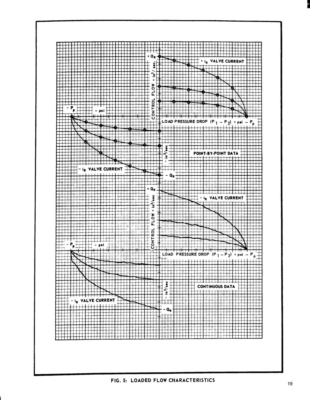
7 4.3.5 Temperature Range - The intended fluid and ambient temperature operating ranges for the servovalve should be specified. If no ambient temperature range is given it is assumed equal to the fluid temperature range. Normal temperature ranges for servovalves supplied for military applications are the following: Flow Polarity - The recommended positive flow polarity for a four-way valve is flow out port 1 and flow in port 2. These flows should result with positive input current (see Section 4.2.3). With a three-way valve positive input current should give flow out port 1. Flow polarity can be determined from the control port pressures during a blocked load test (see Section 4.4.6) Internal Leakage - The maximum allowable value for internal leakage should be specified, based upon manufacturer's recommendations, and each valve should be tested to determine its maximum internal leakage flow. This test can be a continuous plot of internal leakage throughout the null region (as shown in Figure 2) or may be a visually obtained flow reading taken at the peak value observed (see Section 5.4.4). Very low flow valves may require a stop watch and beaker technique to obtain an accurate measurement of internal leakage Supply Fluid Filtration - Manufacturers should recommend the system filtration ratings to be used for normal life of the servovalve, and this recommendation should appear on the valve installation drawing. If magnetic system filtration is required, a suitable note should be included External Leakage - There should be no external leakage from the valve throughout all operational and environmental ranges, including operation under conditions of proof pressures specified in Section Static Performance Rated Flow - Valve rated flow should be specified for stated values of rated current and rated valve pressure drop (or for a stated supply pressure and load pressure drop). Each valve should be tested to pass the specified rated flow of each polarity with acceptable tolerance when operated under specified input current and pressure conditions. The usual tolerance for rated flow is ±10% when operating under standard test conditions (see Section 5.2). Rated flow is usually specified for either of two valve pressure drop conditions. One is with full supply pressure drop across the valve (no-load flow), and the other is with a load pressure drop of two-thirds supply pressure. The former condition is significant for sizing tubing and manifold lines and for estimating maximum load velocity. The latter rated pressure condition is popular as operation at two-thirds maximum load pressure drop represents the maximum power output condition for a given valve orifice opening. For convenience in the use of semi-automatic flow plotters for valve testing, it is recommended that rated flow be specified as the no-load flow. It is recommended that the valve be designed for mating to the manifold port patterns given in Figure 1. The manifold pattern should be selected for the valve rated flow at full supply pressure drop as listed below: Manufacturers should make available information explaining the internal leakage limits normally held in his products. Lower leakage values can usually be supplied with some degradation of dynamic response and flow linearity in the null region No-Load Flow Characteristics - Specification limits for flow gain, symmetry, linearity, lap region, flow saturation and flow limit (if applicable) are usually best defined in terms of an acceptable tolerance envelope for one side of the no-load flow curve. The maximum hysteresis value may be specified separately, or included in the tolerance envelope. See Figure 3. Each valve should be tested to demonstrate acceptable performance of these no-load flow specifications. These characteristics are best measured by a continuous no-load flow plot (see Section 5.5.3), but can be ascertained by point-by-point data reading (see Section 5.4.5). The tolerance envelope for the no-load flow characteristics should be drawn to the same scales as used for the valve data, thus facilitating use of overlays or preprinted data sheets. Manufacturers should make available normal tolerances held on the no-load flow characteristics of his products. Tighter envelopes can normally be maintained if required, but at a corresponding cost penalty Threshold - Maximum allowable valve threshold should be specified and each valve should demonstrate acceptable threshold performance when operated under standard test conditions. Threshold data should be measured at several points throughout the valve working range. Either a flow plotter or static flow bench can be used to measure valve threshold (see Section or 5.5.4). Manufacturers should make available acceptable threshold limits for his products Blocked Load Characteristics - Specification limits for pressure gain and null pressure should be established for the servovalve operating with blocked control ports. Each valve should be tested to demonstrate acceptable blocked load characteristics. Either a continuous pressure plot or point-by-point data may be used to measure pressure gain, as shown in Figure 4. The valve null pressure can be read from pressure gages in the control lines when the valve is at null. Also, valve polarity can be determined by the swing of the control port pressure gages from their null value with the application of input current (see Paragraph 5.4.2). Manufacturers should make available acceptable limits for pressure gain and null pressures for his servovalves Loaded Flow Characteristics - The variation of control flow with load pressure is generally dependent upon the basic 7.
8 valve design, so is not normally specified for flow control servovalves. If rated flow is specified for a loaded condition, the correspond in no-load flow characteristics are dictated by the valve design. Complete loaded flow characteristics are not normally measured on each valve. The general nature of these characteristics should be determined, however, for each new servovalve by running either continuous plots or point-to-point data on a representative valve (see Paragraphs or 5.5.5). Data is normally presented as a family of curves taken at constant values of input current (see Figure 5) Null Bias and Null Shift - Valve null bias at any time will reflect any permanent null offset, together with any temporary null shift. Initial offset in the valve null bias may be present when the valve is first assembled and a maximum value should be specified for operation under standard conditions. This initial null bias may change during the life of a valve as a result of use and exposure to environments. The uncertainty of the long term null bias should be predicted by the manufacturer for valves having no centering adjustment. Temporary null shifts may occur during exposure to various operating conditions or environments. If system performance is critical, then corresponding specifications for maximum valve null shift should be determined. Normally maximum null shift is specified as the change in null from that present under standard room operating conditions. Valve null shift may be measured with respect to a change in environment or operating condition and when such data is taken it should be presented as plots of null shift recorded during application and removal of the test condition. Null shift is frequently measured for changes in the following conditions. should be measured on a prototype model if performance requirements are critical. Valve dynamic response measured at large input current amplitudes will saturate at higher frequencies due to limited output of the torque motor and valve intermediate stages. With low input current amplitude, valve threshold effects produce distorted output waveforms. In either case, departure from sinusoidal waveforms can produce ambiguous and even meaningless response data. The recommended peak-to-peak amplitude of the input current for dynamic response testing is one-half the valve rated current Phase Angle - Data on valve phase angle, when taken, should be presented on the same plot as amplitude ratio (see Figure 10). The general comments and specification recommendations of the preceding section apply equally to phase angle measurements. Manufacturers will often measure the frequency of the 90º phase point as a quick check of valve dynamic response. When complete valve dynamic response is desired, data should be taken throughout the frequency range from the reference lower frequency (usually 5 or 10 Hz) to the frequency where the valve exhibits 96º phase lag. 5.0 RECOMMENDED TEST PROCEDURES 5.1 Test Equipment and Facilities Schematics are given in conjunction with the test descriptions which follow in order to illustrate the equipment requirements. Some equipment especially suited to the purpose is available from various manufacturers and a partial listing of this equipment has been included. Null shift with acceleration is usually given as percent/unit acceleration (see ). Normally tests of valve null shift are only conducted on a representative sample of production valves. Manufacturers should make available data giving typical null shift performance for his products. 4.5 Dynamic Performance Amplitude Ratio - Data for a complete plot of amplitude ratio versus sinusoidal input current is not normally taken on each production valve. Often, however, the manufacturer will check valve amplitude ratio at one or two frequencies in order to assess valve stability. When frequency response is critical, a tolerance envelope should be used to specify amplitude ratio as indicated in Figure 10. This envelope will usually specify response under standard operating conditions (see Section 5.2). Valve frequency response will vary with fluid temperature, supply and return pressures, and input current amplitude, so these test conditions should be specified and stated on the response data sheet. Valve dynamic response will generally depreciate at both high and low temperatures. Predictions of the valve response at temperature extremes are generally unreliable and When selecting individual test instruments, gages, etc. to be used in special test set-ups for measuring servovalve performance, the accuracies of the equipment chosen must be compatible with the precision of the tests to be performed. Most hydraulic and electrical test equipment requires frequent calibration to maintain suitable accuracy. In addition, most hydraulic flowmeters require reading corrections to account for fluid viscosity variations. These variations can be expected with fluid use or changing fluid temperature, or between different fluid types. In designing special equipment set-ups, care should be exercised to minimize unnecessary line lengths and hydraulic fittings so as to reduce line pressure drops. Likewise, tubing sizes should be selected for compatibility with peak flows to be encountered. Location of static pressure gages at the valve manifold will avoid inaccurate indications of actual valve pressures. The input to electrohydraulic servovalves is defined as the current in the servovalve coils. In order to provide for unambiguous testing of servovalves, the electrical equipment used should be capable of providing undistorted current waveforms, irrespective of the valve coil inductance and back emf's due to valve action. Hence, a high output impedance driver, such as a current feedback dc amplifier, is especially well suited. Valves supplied with three lead coil connections are generally intended for use with differential electrical inputs. Accurate measurement of true differential current with most driving amplifiers is usually inconvenient, so the general practice is to drive the coils in series with a single-ended (two wire) connection. A single-ended amplifier may be connected to pins B C of a three pin valve connector to achieve full coil operation. 8.
9 Measured currents will correspond to the series coil connection, so will be one-half corresponding differential currents. Valve performance measured in this manner will accurately represent differential coil operation. Several manufacturers and users are now utilizing semi-automatic, continuous data plotting equipment to obtain static performance characteristics for flow control servovalves. Either continuous or point-by-point test equipment may be employed for static valve testing. The recommended test procedures which follow recognize either technique as acceptable. 5.2 Standard Test Conditions Unless specified otherwise, flow control servovalves should be tested under the following standard conditions: inductance can be determined. If a suitable phase angle meter is not available, actual construction of the voltage vector diagram from measurement of e T, e R and e V can establish the magnitude of e L with sufficient accuracy for determination of valve coil inductance Insulation Resistance - The insulation resistance of the valve coil and connections can be measured by the steps below. Valves need not be pressurized for the insulation test; however, wet coil and stale coil valves should be filled with hydraulic fluid during the test. Step 1 Apply a dc voltage of five times the maximum anticipated coil voltage, or 200 volts (whichever is greater) between the combined coil connections (connected together) and the valve body (using Industrial Instruments, Inc. Type P6 Voltage Tester, or equivalent). Step 2 Maintain the test voltage for 60 seconds. Step 3 With the test voltage still applied, measure the current flow. 5.3 Electrical Tests Coil dc Resistance - The dc resistance of the coil, or coils, should be measured with an accuracy of ±1% for 70ºF ±2ºF ambient temperature. If the valve utilizes a three or four lead coil connection, the resistance of each side of the total coil should be measured separately. A conventional Wheatstone bridge type electrical test instrument is acceptable for measuring coil resistance (Industrial Instruments, Inc. Type RN). The valve need not be supplied with pressurized oil during measurement of coil resistance Coil Inductance - The recommended procedure for measuring valve coil inductance establishes the apparent inductance to signal frequency variations. This inductance value is suitable for transfer Step 4 The applied voltage level divided by the measured current value gives the insulation resistance. (Equivalent electrical instruments may give the insulation resistance directly.) No evidence of insulation breakdown should be apparent and the insulation resistance should exceed 100 megohms. ` 5.4 Static Performance Test- Point-by-Point Data The valve should be securely mounted to a suitable static test stand. Figure 12 gives the hydraulic schematic for a static test stand utilizing return line flowmeters Null -The procedure to determine valve null follows. Step 1 Open the return line shut-off valve. Step 2 Close the load valve to block the servovalve control ports. Step 3 Apply rated pressure to the valve under test by opening the supply line valve and adjusting the pressure regulating valve. The supply pressure to the valve should be adjusted until Step 6 To eliminate electrical hysteresis, continue cycling the input current slowly between positive and negative values while gradually decreasing the maximum current levels. The total coil inductance should be measured with the valve operating under conditions specified in 5.2. The recommended test set-up is shown in Figure 11. function representation in system dynamic studies. A suitable audio frequency oscillator is connected to drive the total valve coil, connected in series with a precision resistor. The oscillator should have sufficient power output to supply undistorted input current of at least one-half rated value. The oscillator frequency is set at 50 Hz and the amplitude adjusted to give a peak-to-peak current amplitude of one-quarter valve rated current. The vectorial relationship of the voltages is indicated by a sketch in Figure 11. The voltage drop,e L, across the apparent valve inductance is determined by indirect measurement. From this, the total valve coil Step 4 Apply full positive rated current. Step 5 Decrease the input current slowly to zero, then increase current in a negative direction to full negative rated current. When the current is decreased to zero by this method, note the readings of the control port pressure gages, P 1 and P 2 Step 7 If the load pressure drop, P 1 - P 2, is not zero, the valve is off-null. To null the valve, slowly increase the input current in the proper direction to equalize the control port pressures. A positive input current will tend to increase the pressure at port 1. Step 8 When the load pressure drop is zero, note the value of input current. Then, slowly increase the input current in the same direction until the load pressure gage readings change. Stop 9.
10 and reverse the direction of applying current input until the load pressure drop is again zero. Note the value of input current. The two values of current will differ due to valve threshold. Step 9 The null bias current (in ma) is the average of the two current values noted in the preceding step Polarity - Correct valve polarity can be determined from the control port pressure indications following step 4 of Pressure at control port 1 should be equal to Pp and pressure at control port 2 should equal PR' Pressure Gain - Data for a plot of the pressure gain characteristic (see Figure 4) may be obtained by the following procedure. particularly evident through the null region where the control flow is determined by differences of nearly equal flow readings. Step 7 A plot of the data obtained in step 6 will provide valve linearity, symmetry, flow gain, and flow saturation information. Minor flow gain discontinuities will not necessarily be uncovered by this point-by-point test method Hysteresis - Maximum valve hysteresis can be measured quite accurately by the following procedure. Step 1 Perform steps 1 through 4 of the preceding section (5.4.5). Step 2 Decrease the input current slowly to full negative rated current. Step 3 Increase the input current slowly to full positive rated current. Slowly decrease input current to approximately 10% of positive rated current. Note the current value (io) and the equivalent flowmeter reading. Step 4 Decrease the input current to full negative rated, then increase the current in a positive direction, continuing through zero and the value io until the same flowmeter reading is obtained. Record the input current (i1 ) at this point. Step 5 The valve hysteresis is given by Internal Leakage - Data for a plot of valve leakage flow versus input current (see Figure 2) may be obtained by the following procedure. Often a statement of maximum internal leakage (which exists at the null point) may suffice in lieu of a plot. Step 1 Follow steps 1 through 4 of Step 2 Slowly decrease the input current, stopping at suitable points to record the flowmeter readings. Care should be taken to obtain the maximum flowmeter reading which will occur at the valve null. Note that the null bias current obtained here will be different from that of by approximately one-half the valve hysteresis. Step 3 Continuation of step 2 until full negative input current is obtained will provide data for a complete internal leakage plot. A minimum of eleven data points is recommended. This data is also necessary to obtain the no-load flow plot of the following section No-Load Flow Characteristics - Data for a no-load flow plot (see Figure 3) may be obtained by the following procedure. Step 1 Open the return line shut-off valve. Step 2 Open the load valve. Step 3 Apply rated pressure to the valve, as in step 3 of Under conditions of maximum control flow, special care should be exercised to maintain full valve rated pressure drop. Step 4 Apply full positive rated current. Step 5 Decrease the input current in the same increments utilized in steps 2 and 3 of At each value of input current, record the flowmeter readings. Step 6 Calculate the equivalent control flow by subtracting the internal leakage flow values from the corresponding flow readings obtained in step 5. It should be noted that this method of determining control flow (i.e., subtracting internal leakage from total return line flow) is subject to error, as many valves are influenced by flow reaction forces. Since there is no control flow from the valve during the internal leakage test, the correspondence of like data points is upset. These errors will be Threshold - Valve threshold may be obtained by the following procedure Step 1 Perform steps 1 through 3 of Section Step 2 Slowly apply input current of one polarity, stopping near 10%. rated input, Note the current (io) and equivalent flowmeter reading. Step 3 Slowly decrease the input current until a change in the flowmeter reading is noted. At this point, note the input current indication (i1 ). Step 4 The incremental currentai = io - i1 is a measure of valve threshold. Step 5 Repeat steps 2 through 4, stopping at other values of input current. Readings taken near the null point will be most accurate due to increased flowmeter sensitivity. Step 6 The largest increment of input current obtained should be recorded as the valve threshold, and this can be stated in percent of ir. 10
11 5.4.8 Loaded Flow Characteristics Step 1 Perform steps 1 through 4 of Section Step 2 Without changing the input current from the full positive rated value, commence closing the load valve. Step 3 At suitable points, stop and obtain readings of flow, P 1 and P 2. About five sets of data should be obtained at nearly equal increments of load pressure drop. Step 4 Repeat step 3 at other constant values of input current, as appropriate. Step 5 For each set of data from steps 3 and 4, calculate the load pressure drop (Pi - P2). Also, correct the return line flow data for the corresponding internal leakage flows obtained at like input current values (see 5.4.4). Step 6 From the calculations of step 5, the valve loaded flow characteristics may be plotted (see Figure 5) Proof Pressure - The valve may be subjected to rated proof pressures by the following procedure. Step 1 Close the return line valve. Step 2 Close the load valve. Step 3 Apply rated pressure to the valve supply port by opening the supply line valve and adjusting the pressure regulating valve. Step 4 Apply full positive rated current, +ir, then apply _'R. No external leakage should be present. Step 5 Open the return line valve. Step 6 Increase the valve supply pressure to 11/2% Pp by adjusting the pressure regulating valve. Step 7 Repeat step Null Shift with Supply Pressure - Data for a plot of valve null shift with supply pressure variations may be obtained by the following procedure. Step 1 Null the valve as in Step 2 Decrease the supply pressure in suitable increments by adjusting the pressure regulating valve. At each value of supply pressure, repeat steps 7, 8 and 9 of the valve null procedure to obtain the corresponding null bias currents. Step 3 Data of step 2 maybe plotted as in Figure Null Shift with Return Pressure - Valve null shift with changing return line pressure may be presented as in Figure 8. Data for such a plot may be obtained by the following procedure. Step 1 Null the valve as in Step 2 Slowly close the return line valve to establish suitable increments of back pressure. At each back pressure value, repeat steps 7, 8 and 9 of the valve null procedure to obtain corresponding null bias currents. Step 3 Data from step 2 may be plotted as in Figure Null Shift with Quiescent Current - Data for a plot of valve null shift with quiescent current may be obtained by the following procedure. Step 1 Null I the valve as in Step 2 Reconnect the valve coils to give a differential coil connection (if necessary). See sketch in Figure 9. Step 3 Increase the coil quiescent current in suitable increments, and at each current value repeat steps 7, 8 and 9 of the valve nulling procedure to obtain corresponding null bias currents. Step 4 Data from step 3 may be plotted as in Figure Null Shift with Temperature - The recommended test equipment for this test utilizes a simple position servoloop to provide continuous null bias currents. See Figure 13. Step 1 Open the return line valve. Step 2 Set both the hot and cold oil supply pressures to the rated supply pressure. Step 3 Adjust the mixing valve to give 100 F oil supply temperature to the valve under test. Record the input current. Step 4 Readjust the mixing valve to establish suitable increments of increasing oil supply temperature. At each successive temperature allow the valve to stabilize for one minute preceding the input current reading. It may be desirable to introduce some dither signal into the system to avoid piston stiction. Step 5 Continue to obtain null bias current readings for temperature increments to the rated maximum temperature; then decrease oil temperature in like increments to the minimum oil temperature. Similarly, increase the temperature and obtain null bias readings to F. Step 6 The data may be presented as in Figure Null Shift with Acceleration -The recommended equipment for this test utilizes electrical pressure transducers at the control ports as indicated in Figure 14. The transducer outputs may be connected to give a differential load pressure indication, following appropriate transducer calibration. The following procedure may then be utilized to measure the valve null shift with acceleration inputs. Step 1 Mount the valve and manifold on a suitable acceleration input device (centrifuge for constant acceleration, shaker for vibration inputs, or drop equipment for shock). Step 2 Open the return line valve. Step 3 Apply rated supply pressure to the valve. Step 4 For constant acceleration inputs, the null bias current necessary to obtain zero load pressure drop may be determined for appropriate acceleration values. Step 5 For vibration inputs, an oscillating load pressure signal will exist. The peak-to-peak amplitude of the null shift may be determined by monitoring the load pressure signal on a dc oscilloscope, while slowly varying the bias input current. The algebraic difference of bias current values necessary to produce zero load pressure drop, first at one peak and then at the other peak, is the peak-to-peak null bias current. Step 6 For shock inputs, a dynamic recording of the differential load pressure signal is required. The equivalent null bias currents can then be determined from the pressure gain data of Section Static Performance Tests- Continuous Data The use of continuous data plotting equipment for recording servovalve static performance information is rapidly displacing point-by-point testing procedures. In general, more complete data is obtained more expeditiously through the use of semi 11
12 automatic plotting equipment. Figure 15 gives a simplified schematic representative of this equipment. Valve output flow is supplied to a large capacity piston equipped with motion transducers. Piston velocity is equivalent to the volumetric flow from the valve and an electrical signal proportional to the piston velocity can be recorded. A programmed current sweep input is supplied to the valve. Usually the sweep signal is a triangular waveform as sketched below. Detailed operation and calibration procedures are available from these manufacturers to explain the correct use of their equipment. Frequent calibration of plotting equipment is especially important for accurate data presentation. Electrical circuits within the plotters should be arranged to produce positive plotter displacements with the recommended standard positive current, flow and pressure specifications of paragraphs and Prior to each test the zero axes should be established by actually plotting zero Y input versus X sweep and zero X input versus Y sweep. This can be accomplished by manually rotating the corresponding axis centering control Blocked Load Characteristics - Pressure gain, polarity and null characteristics can be ascertained from the following procedure. Step 1 Connect the valve, both hydraulically and electrically, to the plotting equipment. Step 2 Close the control line valves. Step 3 Open the return line valves. Step 4 Set the valve supply pressure to the rated value by opening the supply valve and adjusting the pressure regulating valve. The adjustment should compensate for any return line back pressure. Step 5 With the plotting pen raised, automatically cycle the input current sweep several times between plus and minus rated current values, stopping at zero input current. Step 6 Establish a plotter configuration to permit recording load pressure drop along the Y axis and input current along the X axis. Use scale factors to give AP max = ±PP and i max ~ ±0.2 ir, The piston position prior to the sweep cycle is near one end, so the piston traverses the cylinder and back during the cycle. The sweep duration is programmed such that the piston does not bottom during the cycle. A low gain position feedback signal with bias adjustment is used to maintain the piston position prior to a sweep input. During a current sweep, the valve is operating open loop. Most continuous data plotting equipment for flow servovalves is supplied with control port pressure instrumentation. By closingoff the control line shut-off valves, plots of valve pressure gain characteristics can be made. For these plots, the amplitude of the current sweep can be adjusted for a suitable cycle about the valve null. Some plotters can produce valve loaded flow characteristics. Different techniques for obtaining loads are utilized. The technique illustrated in Figure 15 uses a manually adjusted load line valve to vary the load pressure drop. Some plotter pistons can be loaded with dead weights to furnish flow versus input current plots at constant values of load pressure drop. It is usually possible to obtain plots of valve internal leakage flow versus input current by blocking the control lines and diverting return line flow to the plotter piston. A half-sweep input commencing at +ir can be utilized to produce the internal leakage plot. At the present time, two manufacturers are known to have complete data plotting equipment commercially available for testing flow control servovalves. These manufacturers are (1) Industrial Measurements Corporation (Model 11 Flow Plot ter), Pomona, California (2) Moog Inc. (Model TE 1004 Flow Plotter), East Aurora, New York Step 7 Set the automatic current sweep to approximately ±0.2 ir maximum (or, as appropriate for the valve under test). Step 8 With the plotting pen still raised, automatically cycle the input current between values set in step 7. During cycling, ascertain that pen motion is unrestricted and that a sufficiently slow sweep is in use to assure a smooth plot, free of recorder dynamic effects. Step 9 Lower the plotter pen and record the pressure gain characteristic for one complete current sweep, as in Figure 4. Step 10 The slope of the plot in the region between ±40% Pp is the valve pressure gain. Step 11 Correct valve polarity is indicated by positive differential pressures ( P = Pi - P2) corresponding to positive input current. Step 12 The valve null bias is assumed to be midway between the abcissa intercepts of the pressure gain plot Internal Leakage - A plot of the valve internal leakage may be obtained by the following procedure. Step 1 Repeat steps 1 and 2 of the preceding section. Step 2 Set the return line shut-off valves to allow return flow to pass to the flow metering piston. Step 3 Establish a plotter configuration to permit recording return line flow along the Y axis and input current along the X axis. Use scale factors to give reasonable plotter deflections for the maximum leakage flow value and to allow i max = ±ir. 12
13 Step 4 Set the input current sweep for a half cycle plot starting at +ir ' Some plotters are not equipped for half cycle plots, so will require a manually controlled sweep current input. Step 5 Apply rated supply pressure to the valve. The plotter piston will commence moving, so immediately lower the plotter pen and introduce the input current described in step 4. Note that the sweep speed is sufficiently slow, especially through the null region, to give a smooth, accurate plot. See Figure 2. Step 6 Should the piston bottom prior to the completion of the previous step, or should another plot be required and insufficient piston stroke remain, the piston must be moved back to the starting end. This will require a temporary change in the shut-off valve configuration of the return and control lines, followed by a repetition of steps 2 and 5 above No-Load Flow Characteristics - Flow gain, linearity, symmetry, hysteresis and saturation may be obtained by the following procedure. Step 1 Repeat steps 1 through 5 of Section Step 2 Open the control I ine valves. Step 3 Establish a plotter configuration to permit recording control flow on the Y axis and input current along the X axis. Use scale factors to permit recording Qmax = ±QR, i max = ±ir Step 4 With the plotter pen raised, automatically cycle the input current throughout the entire range. During the sweep note that the flow piston does not bottom, that the supply and return pressure values remain sufficiently stable, and that the sweep speed is sufficiently slow to avoid excessive plotter dynamic inaccuracies. Step 5 Lower the plotter pen and obtain a no-load flow plot as in Figure 3. Step 6 Acceptable flow gain, linearity, symmetry, and saturation are best ascertained by use of a transparent overlay upon which are drawn allowable envelope limits. Step 7 Valve hysteresis can be measured as the maximum width (iw) of the no-load flow plot. Percent hysteresis is given by Threshold - Valve threshold can be determined on continuous data plotting equipment by the procedure given below. Step 1 Following the no-load flow plot obtained by the procedure of Step 4 Threshold may be determined by the maximum width of the threshold plot (iw). Percent threshold is given by Observation of plotter piston displacement during this test will be necessary to avoid bottoming of the piston Loaded Flow Characteristics - The change in control flow with load pressure may be plotted by the following procedure. Step 1 Repeat steps 1 through 5 of Section Step 2 Establish a plotter configuration to permit recording control flow on the Y axis and load pressure drop on the X axis. Use scale factors to permit Qmax = ±QR and AP max = ±PP. Step 3 Set the input current to a constant value of +ir: Step 4 Open one control line shut-off valve. Step 5 With the plotter pen raised, slowly open the other control line valve. By trial and observation, establish a rate for opening the control line valve such that maximum flow can be obtained prior to bottoming of the plotter piston. Between trials, apply negative input currents to move the piston back to the starting point; then close the control line valve. Step 6 Lower the plotter pen and repeat step 5 to obtain one plot of the family shown in Figure 5. Step 7 Repeat this procedure to obtain plots at other appropriate values of input current. 5.6 Dynamic Tests The valve dynamic response while operating into no-load with sinusoidal current inputs can be determined by equipment equivalent to that illustrated in Figure 16. In this equipment, valve control flow is supplied to a low mass, low friction actuator. Motion of the actuator is detected by electrical transducers. The design of the actuator should be such that negligible dynamic differential pressure variations exist in the frequency range of interest (usually to several hundred cycles per second). In this way the valve dynamic characteristics in the presence of a true no-load can be ascertained. A low gain, quasi-static position feedback signal is utilized for nominal centering of the response actuator. A linear motion velocity generator is recommended for deriving dynamic flow signals. The servoamplifier must be designed to supply sinusoidal input currents to the servovalve throughout the test frequency range. Input current signals may be obtained across a resistor in series with the valve coils. Section 5.5.3, increase the sensitivities of both the flow and current recording channels so that changes corresponding to the valve threshold will be discernable. Step 2 With the plotter pen lowered, slowly adjust (manually) the input current until a flow change is recorded. At this point, slowly reverse the direction of application of current until a corresponding change of flow is noted. Repeating this procedure will establish a threshold plot for the valve. Step 3 Step 2 may be repeated at various input current levels near the valve null to determine the consistency of the threshold indication. Observation of plotter piston displacement during this test will be necessary to avoid bottoming of the piston. The amplitude and phase relationship of flow to current may be determined directly from an oscilloscope Lissajous pattern, or by use of suitable transfer function measuring instrument. Considerable caution must be exercised when setting-up a servovalve dynamic test installation to achieve adequate pressure regulation. In any new installation the dynamic pressure variations in both the supply and return lines should be observed during a typical test. Excessive pressure variations should be eliminated by careful choice of regulator, accumulators and plumbing configuration. A significant source of ambiguity and data inaccuracy can arise if the flow waveform is nonsinusoidal. Distortions of the flow waveform are often introduced by valve nonlinearities caused by either too small or too large input current amplitudes. With 13
14 commercial dynamic measuring equipment, the results obtained with distorted waveforms depend upon the specific design of the equipment. Since wide differences in data arise under these conditions, careful monitoring of both the flow and current waveforms is essential for accurate determination of servovalve dynamic characteristics. Equipment especially designed for servovalve dynamic testing is available from at least two manufacturers. (1) Industrial Measurements Corporation Model 601 (2) Moog Inc. Model TE Amplitude Ratio - Data for a plot of valve amplitude ratio (see Figure 10) may be obtained by the following procedure. Step 1 Mount the valve to be tested on the response actuator. Connect the valve coils to the servoamplifier. Step 2 Open the return line shut-off valve. Step 3 Pressurize the valve to rated pressure by opening the supply line and adjusting the pressure regulating valve. This adjustment should compensate for any return line back pressure. With proper polarity of the valve and test equipment, the position feedback should tend to center the actuator. Step 4 Set the oscillator frequency to a prescribed reference frequency, usually 5 Hz. Step 5 Increase the oscillator output amplitude until the desired input current amplitude is achieved. A peak-to-peak input current of one-half rated is recommended. Observe the actuator velocity signal on the oscilloscope to verify that the actuator does not bottom near the zero velocity points. Slight adjustment of the valve bias current may be necessary to center the response piston. Step 6 Adjust the oscilloscope controls to produce a reference height (peak-to-peak piston velocity) and width (peak-to-peak current) for the output/input Lissajous pattern. Step 7 Increase the oscillator frequency to the next test point. Step 8 If necessary readjust the oscillator amplitude to maintain the reference peak-to-peak input current. Step 9 Measure and record the velocity amplitude with respect to the reference amplitude in the manner prescribed by the equipment manufacturer. Some equipment furnishes direct readings in decibels. With other equipment, db may be. calculated from the measured amplitude ratio, if desired. Step 10 Repeat steps 7, 8 and 9 for the remainder of the test points. Approximately ten data points in the frequency region to the 90 degree phase lag point are desirable Phase Angle - Data for valve phase angle may be obtained concurrently with the amplitude data of the previous section. Step 1 At each frequency setting use a suitable phase meter to ascertain the phase difference between the velocity and current signals. If a suitable phase meter is not available, the phase difference may be determined from the oscilloscope Lissajous pattern. The following may be use 14
15

16

17

18
19

20
Electro-Proportional Terms and Definitions
 Electro-Proportional Terms and Definitions Valve Deadband The span of operation where there is no flow or pressure output for some specified range of command Hydraulic Valve Gain The characteristic relating
MCV102A. Pressure Control Servovalve DESCRIPTION FEATURES ORDERING INFORMATION. BLN Issued: October 1998
 MCV102A Pressure Control Servovalve Issued: October 1998 DESCRIPTION The MCV102A Pressure Control Servovalve (PCS) is a twostage, fourway, closed loop electrohydraulic servovalve that provides an output
G761 Series Servovalves ISO Size 04
 G761 Series Servovalves ISO 137 Size 4 TWO STAGE SERVOVALVES G761 SERIES SERVOVALVES The G761 Series flow control servovalves are throttle valves for 3- and preferably 4-way applications.they are a high
SM4-10/12/15 Servovalves Flows to 57 l/min (15 USgpm) Pressures to 210 bar (3000 psi)
 Pressures to 210 bar (3000 psi)") Vickers Servo Valves SM4-10/12/15 Servovalves Flows to 57 l/min (15 USgpm) Pressures to 210 bar (3000 psi) Released 12/93 651 Introduction Vickers SM4-10/12/15 servovalves can provide system closed loop
Vickers Servo Valves SM4-10/12/15 Servovalves Flows to 57 l/min (15 USgpm) Pressures to 210 bar (3000 psi) Released 12/93 651 Introduction Vickers SM4-10/12/15 servovalves can provide system closed loop
631 Series Servovalves ISO 4401 Size 05
 631 Series Servovalves ISO 4401 Size 05 TWO STAGE SERVOVALVES 631 SERIES SERVOVALVES The 631 Series flow control servovalves are throttle valves for 3- and preferably 4-way applications.they are a medium
SM4-30 Servovalves Flows to 113 l/min (30 USgpm) Pressures to 140 bar (2000 psi)
 Pressures to 140 bar (2000 psi)") Vickers Servo Valves SM4-30 Servovalves Flows to 113 l/min (30 USgpm) Pressures to 140 bar (2000 psi) Released 1/94 653 Introduction Vickers SM4-30 servovalves can provide system closed loop control with
Vickers Servo Valves SM4-30 Servovalves Flows to 113 l/min (30 USgpm) Pressures to 140 bar (2000 psi) Released 1/94 653 Introduction Vickers SM4-30 servovalves can provide system closed loop control with
G761 Series Servovalves ISO Size 04
 G761 Series Servovalves ISO 137 Size 4 TWO STAGE SERVOVALVES G761 SERIES SERVOVALVES The G761 Series flow control servovalves are throttle valves for 3-, and preferably 4-way applications.they are a high
LECTURE 27 SERVO VALVES FREQUENTLY ASKED QUESTIONS
 LECTURE 27 SERVO VALVES FREQUENTLY ASKED QUESTIONS 1. Define a servo valve Servo valve is a programmable orifice. Servo valve is an automatic device for controlling large amount of power by means of very
3/3 servo directional control valve with mechanical position feedback
 Courtesy of CMA/Flodyne/Hydradyne Motion Control Hydraulic neumatic Electrical Mechanical () 426-4 www.cmafh.com 3/3 servo directional control valve with mechanical position feedback Type 4WS2EM...XN...-114
Vickers. Servo Valves. SM4-40 Servovalves. Flows to 151 l/min (40 USgpm) Pressures to 350 bar (5000 psi) Released 1/94
 Pressures to 350 bar (5000 psi) Released 1/94") Vickers Servo Valves SM4-40 Servovalves Flows to 151 l/min (40 USgpm) Pressures to 350 bar (5000 psi) Released 1/94 654 Introduction Vickers SM4-40 servovalves can provide system closed loop control with
Vickers Servo Valves SM4-40 Servovalves Flows to 151 l/min (40 USgpm) Pressures to 350 bar (5000 psi) Released 1/94 654 Introduction Vickers SM4-40 servovalves can provide system closed loop control with
Hydraulic Proportional and Closed Loop System Design
 Hydraulic Proportional and Closed Loop System Design Neal Hanson Product Manager Industrial Valves and Electrohydraulics 1 Electrohydraulics Contents 1. Electrohydraulic Principles 2. Proportional Valve
72 Series Servovalves
 72 Series Servovalves TWO STAGE SERVOVALVES 72 SERIES SERVOVALVES The 72 Series flow control servovalves are throttle valves for 3 and preferably 4-way applications.they are a high performance, two-stage
series 2-Stage Servovalve Rated flows up to 80 l/m Features
 series 65 2-Stage Servovalve Rated flows up to 8 l/m Features Maximum operating pressure 15 bar ISO 172-4-4--92 mounting pattern Internal pilot supply (4 port) Suitable for -way or 4-way applications High
Directional servo-valve of 4-way design
 Courtesy of CM/Flodyne/Hydradyne Motion Control Hydraulic Pneumatic Electrical Mechanical (0) 426-54 www.cmafh.com Directional servo-valve of 4-way design Type 4WSE3E 32 Size 32 Component series 5X Maximum
STAR. series. Servo proportional valve Rated flows up to 80 l/m. Features
 STAR series 65 Servo proportional valve Rated flows up to 8 l/m Features Maximum operating pressure 15 bar ISO 172-4-4--92 mounting pattern Internal pilot supply (4 port) Suitable for -way or 4-way applications
771, 772, 773 Series Servovalves
 771, 772, 773 Series Servovalves TWO STAGE SERVOVALVES 771/2/3 SERIES SERVOVALVES The 771/2/3 Series flow control servovalves are throttle valves for 3- and preferably 4-way applications.they are a high
STAR. series. 2-Stage Servovalve Rated flows up to 7 l/m. Features
 STAR series 2 2-Stage Servovalve Rated flows up to 7 l/m Features Miniature design Maximum operating pressure 315 bar ISO 1372-1-1--92 mounting pattern Internal pilot supply (4 port) Suitable for 3-way
KVF. Flow Control Servovalve (FCS) DESCRIPTION FEATURES ORDERING INFORMATION KVF X X X X X. BLN Issued: February 2004
 DESCRIPTION FEATURES ORDERING INFORMATION KVF X X X X X. BLN Issued: February 2004") DESCRIPTION KVF Flow Control Servovalve (FCS) Issued: February 004 The KVF Flow Control Servovalve is a precision servovalve that provides an output flow rate proportional to a low power electrical input
DESCRIPTION KVF Flow Control Servovalve (FCS) Issued: February 004 The KVF Flow Control Servovalve is a precision servovalve that provides an output flow rate proportional to a low power electrical input
STAR. series. 2-Stage Servovalve Flight Simulation Motion Control. Features
 STAR series 99 2-Stage Servovalve Flight Simulation Motion Control Features Maximum operating pressure 14 bar ISO 1372-6-5--92 mounting pattern Internal pilot supply (4 port) Low hysteresis & zero point
Código de rotor bloqueado Rotor bloqueado, Letra de código. Rotor bloqueado, Letra de código
 Letra de código Código de rotor bloqueado Rotor bloqueado, Letra de código kva / hp kva / hp A 0.00 3.15 L 9.00 10.00 B 3.15 3.55 M 10.00 11.00 C 3.55 4.00 N 11.00 12.50 D 4.00 4.50 P 12.50 14.00 E 4.50
Single Pole Circuit Protectors 55. Multi-Pole Circuit Protectors 56. Configurations 58. Operating Characteristics 59.
 Single Pole Circuit Protectors 55 Multi-Pole Circuit Protectors 56 Configurations 58 Operating Characteristics 59 Delay Curves 60 Specifications 61 Decision Tables 62 SINGLE POLE CIRCUIT PROTECTORS The
series 2-Stage Servovalve Rated flows up to 20 l/m Features
 series 46 2-Stage Servovalve Rated flows up to 2 l/m Features Standard & high response versions Maximum operating pressure 15 bar ISO 441---4 mounting pattern Internal pilot supply (4 port) Suitable for
Appendix A: Motion Control Theory
 Appendix A: Motion Control Theory Objectives The objectives for this appendix are as follows: Learn about valve step response. Show examples and terminology related to valve and system damping. Gain an
STAR. series. 2-Stage Servovalve Rated flows up to 20 l/m. Features
 STAR series 454 2-Stage Servovalve Rated flows up to 2 l/m Features Standard & high response versions Maximum operating pressure 15 bar ISO 172-2-2-2 mounting pattern Internal pilot supply (4 port) Suitable
Schneider Feinwerktechnik
 Electro pneumatic mass-flow servo valve Model PVM 064/065 Single stage industrial type PVM 064 PVM 065 Sub plate mounting construction according to DIN ISO 55 99 NG2 Attention: The holes for mounting screw
MCV106A. Hydraulic Displacment Control-PV DESCRIPTION FEATURES ORDERING INFORMATION. BLN Issued: March 1991
 DESCRIPTION MCV106A Hydraulic Displacment Control-PV Issued: March 1991 The MCV106A Hydraulic Displacement Control (HDC) is a costeffective hydraulic pump stroke control which uses mechanical feedback
Utilization of Electric Power Laboratory 3 rd Year G2: Testing & Characteristic of MCCB Used in Commercial and Industrial Applications
 G2: Testing & Characteristic of MCCB Used in Commercial and Industrial Applications Contents 1. Laboratory Objective... 4 2. MECHANICAL OPERATION TESTS... 4 2.1 Purpose... 4 2.2 Procedure... 4 2.3 Results...
350 Series Electrohydraulic Actuators
 March 2000 350 Series Electrohydraulic Actuators 350 Series electrohydraulic actuators (figure 1) use a dc milliampere signal to operate a variety of slidingstem or rotary valves for proportional or two-position
Servo and Proportional Valves
 Servo and Proportional Valves Servo and proportional valves are used to precisely control the position or speed of an actuator. The valves are different internally but perform the same function. A servo
Application Notes. Calculating Mechanical Power Requirements. P rot = T x W
 Application Notes Motor Calculations Calculating Mechanical Power Requirements Torque - Speed Curves Numerical Calculation Sample Calculation Thermal Calculations Motor Data Sheet Analysis Search Site
Application Information
 Moog Components Group manufactures a comprehensive line of brush-type and brushless motors, as well as brushless controllers. The purpose of this document is to provide a guide for the selection and application
SL Series Application Notes. SL Series - Application Notes. General Application Notes. Wire Gage & Distance to Load
 Transportation Products SL Series - Application Notes General Application Notes vin 2 ft. 14 AWG The SL family of power converters, designed as military grade standalone power converters, can also be used
series 2-Stage Servovalve Rated flows up to 55 l/m Features
 series 456 2-Stage Servovalve Rated flows up to 55 l/m Features Standard & high response versions Maximum operating pressure 15 bar Special mounting pattern Internal pilot supply (4 port) Suitable for
INSTRUCTION MANUAL 276-5XX SERIES 4-20MA TRANSMITTERS
 INSTRUCTION MANUAL 276-5XX SERIES 4-20MA TRANSMITTERS 276-515 4 Phase (210 Meters) Amphenol 276-525 4 Phase (210 Meters) Weather-Tight, Explosion proof (UL, CSA) 276-517 7 Phase (220/240 Meters) Amphenol
4-way directional servo-valve
 4-way directional servo-valve RE 29564/09.10 Replaces: 01.07 1/12 Type 4WS.2E Size 6 Component series 2X Maximum operating pressure 315 bar Maximum flow 48 l/min HD5994 Table of contents Contents age Features
D660 Series Servo-Proportional Control Valves with Integrated Electronics ISO 4401 Size 05 to 10
 D660 Series Servo-Proportional Control Valves with Integrated Electronics ISO 4401 Size 05 to 10 OVERVIEW Section Page MOOG SERVO-PROPORTIONAL CONTROL VALVES Overview 2 3 Technical Data 4 5 Electronics
Application Note CTAN #234
 Application Note CTAN #234 The Application Note is pertinent to the Unidrive SP Family A Guide to Tuning the Unidrive SP Introduction: The Unidrive SP provides a number of features that greatly assist
Jet Pipe Servovalves
 Servovalves OVERVIEW Section Page MOOG JET PIPE SERVOVALVES Overview 2 3 Technical Data 4 6 Electrical Characteristics 7 Performance Specs. 8-15 Installation Procedures 16-17 Ordering Information 18-19
Fisher 546 Electro Pneumatic Transducer
 546 Transducer Product Bulletin Fisher 546 Electro Pneumatic Transducer Fisher 546 transducers receive a direct current input signal and use a torque motor, nozzle flapper, and pneumatic relay to convert
APS 400 ELECTRO-SEIS. Long Stroke Shaker Page 1 of 5. Applications. Features
 Long Stroke Shaker Page 1 of 5 The APS 400 ELECTRO-SEIS is a force generator specifically designed to be used alone or in arrays for studying dynamic response characteristics of various structures. It
APS 113 ELECTRO-SEIS Long Stroke Shaker with Linear Ball Bearings Page 1 of 5
 Long Stroke Shaker with Linear Ball Bearings Page 1 of 5 The ELECTRO-SEIS shaker is a long stroke, electrodynamic force generator specifically designed to be used alone or in arrays for studying dynamic
Exercise 4-1. Flowmeters EXERCISE OBJECTIVE DISCUSSION OUTLINE DISCUSSION. Rotameters. How do rotameter tubes work?
 Exercise 4-1 Flowmeters EXERCISE OBJECTIVE Learn the basics of differential pressure flowmeters via the use of a Venturi tube and learn how to safely connect (and disconnect) a differential pressure flowmeter
STAR. series. 2-Stage Servovalve Rated flows up to 230 l/m. Features
 STAR series 89 2-Stage Servovalve Rated flows up to 2 l/m Features Maximum operating pressure 15 bar ISO 172-5-2 mounting pattern Internal pilot supply (4 port) Suitable for -way or 4-way applications
STAR. series. 2-Stage Servovalve Rated flows up to 75 l/m. Features
 STAR series 55 2-Stage Servovalve Rated flows up to 75 l/m Features Standard & high response versions Maximum operating pressure 15 bar ISO 172-4-4-2 mounting pattern Internal pilot supply (4 port) Suitable
Input, Control and Processing elements
 PNEUMATIC & HYDRAULIC SYSTEMS CHAPTER FIVE Input, Control and Processing elements Dr. Ibrahim Naimi Valves The function of valves is to control the fluid path or the pressure or the flow rate. Depending
Quick Reference Charts
 Quick Reference Charts Adjustable Pressure Switches 0" to 40" H 2 O 7" H 2 O to 15 psig.5 to 1900 psig 35 to 2300 psig 2.3 to 2800 psig 14 to 10000 psig ALUM. STAIN. MONEL BUNA N STAIN. TANTLM. Compact
PERFORMANCE SPECIFICATION SHEET
 INCH-POUND MIL-PRF-83536/15A 12 July 2004 SUPERSEDING MIL-PRF-83536/15 27 March 1992 PERFORMANCE SPECIFICATION SHEET RELAYS, ELECTROMAGNETIC, ESTABLISHED RELIABILITY, 4PDT, LOW LEVEL TO 10 AMPERES, PERMANENT
APS 420 ELECTRO-SEIS Long Stroke Shaker with Linear Ball Bearings Page 1 of 5
 Long Stroke Shaker with Linear Ball Bearings Page 1 of 5 The APS 420 ELECTRO-SEIS shaker is a long stroke, electrodynamic force generator specifically designed to be used alone or in arrays for studying
Air Bearing Shaker for Precision Calibration of Accelerometers
 Air Bearing Shaker for Precision Calibration of Accelerometers NOMENCLATURE Jeffrey Dosch PCB Piezotronics 3425 Walden Avenue, Depew NY DUT Device Under Test S B DUT sensitivity to magnetic field [(m/sec
AP/UP, AP/MIL Series Magnetic Circuit Protectors
 AP/UP, AP/MIL AP/UP, AP/MIL Series Magnetic Circuit Protectors Introduction 68 Single Pole 69 Multi-Pole 70 Configurations 72 Operating Characteristics 73 Delay Curves 74 Specifications 75 Decision Tables
D661-G...A Series Servovalve With Bushing and Integrated 24 Volt Electronics ISO 4401 Size 05
 D661-G...A Series Servovalve With Bushing and Integrated 24 Volt Electronics ISO 4401 Size 05 OVERVIEW Section Page MOOG SERVO-PROPORTIONAL CONTROL VALVES Overview 2 3 Technical Data 4 5 Performance Specs.
Introduction to Vibration & Pulsation in Reciprocating Compressors
 Introduction to Vibration & Pulsation in Reciprocating Compressors Shelley D. Greenfield, P.Eng. Vice President, Design Services sgreenfield@betamachinery.com Luis de la Roche Operations Manager ldelaroche@betamachinery.com
5001TCP SPEED CONTROLLER
 INSTALLATION AND SETTING UP MANUAL 5001TCP SPEED CONTROLLER WARNING Disconnect all incoming power before working on this equipment. Follow power lockout procedures. Use extreme caution around electrical
Directional servo-valve in 4-way design
 Directional servo-valve in 4-way design RE 2983/.11 Replaces: 7.3 1/ Type 4WS.2E... Size Component series X Maximum operating pressure 31 bar Maximum flow 1 l/min HD892 Type 4WSE2ED -X/...K31EV HD893 Type
Specification subject to change without notice! All rights reserved page 1 of 5
 Electro Hydraulic Servo Valve Single Stage Hydraulic Symbol Introduction: The HVM 068 is a single stage servo valve in spool and sleeve construction. It is designed special for low pressure applications
Silencers. Transmission and Insertion Loss
 Silencers Practical silencers are complex devices, which operate reducing pressure oscillations before they reach the atmosphere, producing the minimum possible loss of engine performance. However they
Aug07 Rev A All Paragraphs Revised
 Qualification Test Report Universal MATE-N-LOK* Connector 110-213 28Aug07 Rev A All Paragraphs Revised 1. INTRODUCTION 1.1. Purpose 1.2. Scope Testing was performed on Universal MATE-N-LOK* connectors
5001TCP SPEED CONTROLLER
 VARIABLE SPEED DRIVE CONTROLLER INSTALLATION AND SETTING UP MANUAL 5001TCP SPEED CONTROLLER With PC101 Torque Limit Control WARNING Disconnect all incoming power before working on this equipment. Follow
Chapter 2. Background
 Chapter 2 Background The purpose of this chapter is to provide the necessary background for this research. This chapter will first discuss the tradeoffs associated with typical passive single-degreeof-freedom
D680 Series Mini Direct Drive Valve Piloted Servo-Proportional Control Valves with Integrated Electronics ISO 4401 Size 05 to 08
 D68 Series Mini Direct Drive Valve Piloted Servo-Proportional Control Valves with Integrated Electronics ISO 441 Size 5 to 8 OVERVIEW Section Page MOOG SERVO-PROPORTIONAL CONTROL VALVES Overview 2 3 Technical
DENISON HYDRAULICS Jupiter 500 Driver Card Series S
 Back to Content DENISON HYDRAULICS Jupiter 500 Driver Card Series S20-11712-0 Publ. 9-AM681 E-Mail: denison@denisonhydraulics.com Internet: http://www.denisonhydraulics.com SYSTEM FEATURES SYSTEM FEATURES
INSTRUCTION MANUAL 272-5X5 ANALOG TRANSMITTER (210 SERIES FLOW METERS) 272-5X7 ANALOG TRANSMITTER (220/240 SERIES FLOW METERS)
 272-5X7 ANALOG TRANSMITTER (220/240 SERIES FLOW METERS)") INSTRUCTION MANUAL 272-5X5 ANALOG TRANSMITTER (210 SERIES FLOW METERS) 272-5X7 ANALOG TRANSMITTER (220/240 SERIES FLOW METERS) 272-5X8 BIDIRECTIONAL TRANSMITTER (210/240 SERIES FLOW METERS) TABLE OF CONTENTS
INSTRUCTION MANUAL 272-5X5 ANALOG TRANSMITTER (210 SERIES FLOW METERS) 272-5X7 ANALOG TRANSMITTER (220/240 SERIES FLOW METERS) 272-5X8 BIDIRECTIONAL TRANSMITTER (210/240 SERIES FLOW METERS) TABLE OF CONTENTS
CHAPTER 6 MECHANICAL SHOCK TESTS ON DIP-PCB ASSEMBLY
 135 CHAPTER 6 MECHANICAL SHOCK TESTS ON DIP-PCB ASSEMBLY 6.1 INTRODUCTION Shock is often defined as a rapid transfer of energy to a mechanical system, which results in a significant increase in the stress,
A Practical Guide to Free Energy Devices
 A Practical Guide to Free Energy Devices Part PatD20: Last updated: 26th September 2006 Author: Patrick J. Kelly This patent covers a device which is claimed to have a greater output power than the input
IMPACT REGISTER, INC. PRECISION BUILT RECORDERS SINCE 1914
 IMPACT REGISTER, INC. PRECISION BUILT RECORDERS SINCE 1914 RM-3WE (THREE WAY) ACCELEROMETER GENERAL The RM-3WE accelerometer measures and permanently records, for periods of 30, 60, and 90 days, the magnitude,
Ch. 169 DIESEL SMOKE MEASUREMENT CHAPTER 169. DIESEL SMOKE MEASUREMENT PROCEDURE
 Ch. 169 DIESEL SMOKE MEASUREMENT 67 169.1 CHAPTER 169. DIESEL SMOKE MEASUREMENT PROCEDURE Sec. 169.1. Purpose. 169.2. Scope. 169.3. Definitions. 169.4. Smoke emission test. 169.5. Smoke test cycle. 169.6.
Figure 1 Linear Output Hall Effect Transducer (LOHET TM )
") PDFINFO p a g e - 0 8 4 INTRODUCTION The SS9 Series Linear Output Hall Effect Transducer (LOHET TM ) provides mechanical and electrical designers with significant position and current sensing capabilities.
PDFINFO p a g e - 0 8 4 INTRODUCTION The SS9 Series Linear Output Hall Effect Transducer (LOHET TM ) provides mechanical and electrical designers with significant position and current sensing capabilities.
Finite Element and Experimental Validation of Stiffness Analysis of Precision Feedback Spring and Flexure Tube of Jet Pipe Electrohydraulic Servovalve
 Finite Element and Experimental Validation of Stiffness Analysis of Precision Feedback Spring and Flexure Tube of Jet Pipe Electrohydraulic Servovalve M. Singaperumal*, Somashekhar. S. Hiremath* R. Krishna
Transmitted by the expert from the European Commission (EC) Informal Document No. GRRF (62nd GRRF, September 2007, agenda item 3(i))
 Informal Document No. GRRF (62nd GRRF, September 2007, agenda item 3(i))") Transmitted by the expert from the European Commission (EC) Informal Document No. GRRF-62-31 (62nd GRRF, 25-28 September 2007, agenda item 3(i)) Introduction of Brake Assist Systems to Regulation No. 13-H
Transmitted by the expert from the European Commission (EC) Informal Document No. GRRF-62-31 (62nd GRRF, 25-28 September 2007, agenda item 3(i)) Introduction of Brake Assist Systems to Regulation No. 13-H
PERFORMANCE SPECIFICATION COOLERS, LUBRICATING OIL, AIRCRAFT, GENERAL SPECIFICATION FOR
 INCH-POUND 06 May 2013 SUPERSEDING MIL-PRF-25478C 29 December 1997 PERFORMANCE SPECIFICATION COOLERS, LUBRICATING OIL, AIRCRAFT, GENERAL SPECIFICATION FOR This specification is approved for use by all
STEALTH INTERNATIONAL INC. DESIGN REPORT #1001 IBC ENERGY DISSIPATING VALVE FLOW TESTING OF 12 VALVE
 STEALTH INTERNATIONAL INC. DESIGN REPORT #1001 IBC ENERGY DISSIPATING VALVE FLOW TESTING OF 12 VALVE 2 This report will discuss the results obtained from flow testing of a 12 IBC valve at Alden Research
PERFORMANCE SPECIFICATION SHEET SWITCHES, SENSITIVE, SPDT, UNSEALED
 INCH-POUND 14 June 2010 SUPERSEDING 22 May 2006 PERFORMANCE SPECIFICATION SHEET SWITCHES, SENSITIVE, SPDT, UNSEALED This specification is approved for use by all Departments and Agencies of the Department
Components of Hydronic Systems
 Valve and Actuator Manual 977 Hydronic System Basics Section Engineering Bulletin H111 Issue Date 0789 Components of Hydronic Systems The performance of a hydronic system depends upon many factors. Because
Fincor DC Drives. Flexible & Powerful TYPICAL APPLICATIONS. Conveyor Rugged. Extruder Reliable. Conveyor Simple. Mixer Flexible
 DC Drives Flexible & Powerful single-phase DC drives provide a complete family solution from the compact Series 2120 chassis drive to the powerful Series 2230 and it s feature rich application specific
L. Photo. Figure 2: Types CA-16 Relay (rear view) Photo. Figure 1: Types CA-16 Relay (front view)
 Photo. Figure 1: Types CA-16 Relay (front view)") Figure 1: Types CA-16 Relay (front view) Photo Figure 2: Types CA-16 Relay (rear view) Photo 2 Sub 5 185A419 Sub 6 185A443 Figure 3: Internal Schematic of the Type CA-16 bus Relay or CA-26 Transformer
Figure 1: Types CA-16 Relay (front view) Photo Figure 2: Types CA-16 Relay (rear view) Photo 2 Sub 5 185A419 Sub 6 185A443 Figure 3: Internal Schematic of the Type CA-16 bus Relay or CA-26 Transformer
three different ways, so it is important to be aware of how flow is to be specified
 Flow-control valves Flow-control valves include simple s to sophisticated closed-loop electrohydraulic valves that automatically adjust to variations in pressure and temperature. The purpose of flow control
14 Single- Phase A.C. Motors I
 Lectures 14-15, Page 1 14 Single- Phase A.C. Motors I There exists a very large market for single-phase, fractional horsepower motors (up to about 1 kw) particularly for domestic use. Like many large volume
FEASIBILITY STYDY OF CHAIN DRIVE IN WATER HYDRAULIC ROTARY JOINT
 FEASIBILITY STYDY OF CHAIN DRIVE IN WATER HYDRAULIC ROTARY JOINT Antti MAKELA, Jouni MATTILA, Mikko SIUKO, Matti VILENIUS Institute of Hydraulics and Automation, Tampere University of Technology P.O.Box
Electromagnetic Fully Flexible Valve Actuator
 Electromagnetic Fully Flexible Valve Actuator A traditional cam drive train, shown in Figure 1, acts on the valve stems to open and close the valves. As the crankshaft drives the camshaft through gears
Rexroth Hydraulics. Servo directional valve of 4-way design Type 4WS.2EM RE /03.99
 RE 29 564/03.99 Replaces: 29 563 Servo directional valve of 4-way design ype 4WS.2EM Nominal size 6 Series 2X Maximum operating pressures 210 / 315 bar Maximum flow 40 L/min H//D 5994/98 ype 4WS2EM 6-2X/.E...K17EV
Cold Resistance (Ohm) Note 1
 Note 1") P700L Series Part Numbering System P700L - 72-1.0 Fuse Type Voltage Amp Part Number/Rating Cold Resistance (Ohm) Note 1 Overload Interrupt Time (Second) Nominal Rating - Note 2/3 Maximum I 2 T (Ampere
P700L Series Part Numbering System P700L - 72-1.0 Fuse Type Voltage Amp Part Number/Rating Cold Resistance (Ohm) Note 1 Overload Interrupt Time (Second) Nominal Rating - Note 2/3 Maximum I 2 T (Ampere
Module 9. DC Machines. Version 2 EE IIT, Kharagpur
 Module 9 DC Machines Lesson 38 D.C Generators Contents 38 D.C Generators (Lesson-38) 4 38.1 Goals of the lesson.. 4 38.2 Generator types & characteristics.... 4 38.2.1 Characteristics of a separately excited
CHAPTER 6 INTRODUCTION TO MOTORS AND GENERATORS
 CHAPTER 6 INTRODUCTION TO MOTORS AND GENERATORS Objective Describe the necessary conditions for motor and generator operation. Calculate the force on a conductor carrying current in the presence of the
CHAPTER THREE DC MOTOR OVERVIEW AND MATHEMATICAL MODEL
 CHAPTER THREE DC MOTOR OVERVIEW AND MATHEMATICAL MODEL 3.1 Introduction Almost every mechanical movement that we see around us is accomplished by an electric motor. Electric machines are a means of converting
FLOW CONTROL SERVOVALVES
 FLOW CONTOL SEVOVALVES TWO STAGE SEVOVALVES FO INDUSTIAL APPLICATIONS What moves your world OUTLINE J869 Series flow control servovalves are throttle valves for 3 and preferably 4 way applications. They
Hybrid Stepper Motors
 DINGS Electrical & Mechanical Co., Ltd 3 Quality Performance Flexibility Price WHO IS DINGS? DINGS is a premier supplier of rotary and linear step motors. Based in the greater Shanghai, China area, we
Application of Steering Robot in the Test of Vehicle Dynamic Characteristics
 3rd International Conference on Mechatronics, Robotics and Automation (ICMRA 2) Application of Steering Robot in the Test of Vehicle Dynamic Characteristics Runqing Guo,a *, Zhaojuan Jiang 2,b and Lin
CONTINENTAL HYDRAULICS VED03MX
 CONTINENTAL HYDRAULICS VED03MX HIGH PERFORMANCE, SERVO-PROPORTIONAL DIRECTIONAL CONTROL VALVE 5505 WEST 123RD STREET SAVAGE, MN 55378-1299 / PH: 952.895.6400 / WWW.CONTINENTALHYDRAULICS.COM VED03MX HIGH
Basic Electrical Parameters of Reed Switch Products
 REED SWITCH CHARACTERISTICS MEDER electronic Basic Electrical Parameters of Reed Switch Products Pull-In (PI) is described as that point where the contacts close. Using a magnet, it is usually measured
Displacement Sensor. Model 8739, 8740, 8741
 w Technical Product Information Displacement Sensor 1. Introduction... 2 2. Preparations for use... 2 2.1 Unpacking... 2 2.2 Grounding and potential connection... 2 2.3 Storage... 2 3. Principle of operation...
European Aviation Safety Agency. European Technical Standard Order. ED Decision 2016/013/R Annex II. Subject: FUEL DRAIN VALVES
 European Aviation Safety Agency Date: 5.8.2016 European Technical Standard Order Subject: FUEL DRAIN VALVES 1 Applicability This ETSO provides the requirements which Fuel Drain Valves that are designed
Introduction. What is new and different?
 Introduction ValveExpert was developed for testing servo- and proportional valves using advanced computer technology. Any 4-way flow control valves with flow up to 80 L/min and pressure up to 210 bar can
SPECIFICATION SHEET P700L CURRENT LIMITING FUSE SURFACE MOUNT MODEL
 11525 Sorrento Valley Rd. San Diego, California 92121 (858) 481-0210 SPECIFICATION SHEET P700L CURRENT LIMITING FUSE SURFACE MOUNT MODEL REVISION: A B C D E F G H J DATE: 10/95 2/96 2/00 10/95 2/96 10/98
APPLICATION NOTES VALVE CHECKER M
 APPLICATION NOTES VALVE CHECKER M040-120-001 1 of 16 CONTENTS Chapter Title Page 1. Description 3 2. Specification 7 3. Connecting to valve and plant 8 4. Plant mode operation (in line) 9 5. Checker mode
METAL VAREA-METER STRAIGHT THROUGH TYPE ROTAMETER
 TECHNICAL INFORMATION METAL VAREA-METER STRAIGHT THROUGH TYPE ROTAMETER Electronic Transmitter INTRODUCING THE METAL TUBE VAREA-METER U.S. Filter/Wallace & Tiernan Products straight through metal tube
QUESTION BANK SPECIAL ELECTRICAL MACHINES
 SEVENTH SEMESTER EEE QUESTION BANK SPECIAL ELECTRICAL MACHINES TWO MARK QUESTIONS 1. What is a synchronous reluctance 2. What are the types of rotor in synchronous reluctance 3. Mention some applications
Pressure transmitter for general purpose Type MBS 1700 and MBS 1750
 MAKING MODERN LIVING POSSIBLE Data sheet Pressure transmitter for general purpose Type MBS 1700 and MBS 1750 The compact pressure transmitters MBS 1700 and MBS 1750 are designed for use as a general purpose
SURFACE VEHICLE STANDARD
 400 Commonwealth Drive, Warrendale, PA 15096-0001 SURFACE VEHICLE STANDARD J1287 Issued 1980-06 Reaffirmed 1998-07 REAF. JUL1998 An American National Standard Superseding J1287 JUN93 Measurement of Exhaust
4-way directional servo valve Type 4WS.2E
 RE 29 91/06.02 Replaces: 03.93 4-way directional servo valve Type 4WS.2E Nominal size 16 Series 2X Maximum operating pressure 2/31 bar Maximum flow 3 L/min Overview of contents Contents Page Features 1