INSTRUCTIONS AND PARTS LISJ OF THE N 14 & N 14B../ BOSTITCH* WIRE STITCHERS V BELT DRIVE. USES Ne 15001D HEAp
|
|
|
- Aileen Davidson
- 6 years ago
- Views:
Transcription

1 INSTRUCTIONS AND PARTS LISJ OF THE t A S: f i it;.. N 14 & N 14B../ BOSTITCH* WIRE STITCHERS V BELT DRIVE USES Ne 15001D HEAp When in need of Parts or Service Contact Your Bostitch Distributor. >^ ^-X/." :-v:\:: You will find "BOSTITCH" listed in phone books of most large cities. >M Fasten It Better ad Fasfer ' 5 STAPLERS AND STAPLES i-4' ;v,'.. ;.. 'jsf ^^P^MlMii -.,: r a^p-,-.-:; : ' 'r-fts'r^ift'^"""

2 INSTALLATION, OPERATION AND MAINTENANCE of No. 14 AND No. 14B BOSTITCH WIRE STITCHER WITH No D HEAD ;; CAPACITY: 9/16" SIZE OF WIRE:.017 thru.023 Ribbon No. 1 and 2 Hybar No. 18x20, 19x21'/a, 20x24, 20x25 and 21x25 Flat No. 18, 20, 22, 23, 24 and 25 thru 27 Round CROWN OR STAPLE WIDTH: %", W (Standard), %" and %" SPEED: Up to 300 stitches per minute Note: This book does not include head instructions. It should be used in conjunction with "Instructions and Parts List for No D, 18001D, 18001D27 and 19001D Bostitch Wire Stitcher Heads." 1. INTRODUCTION To obtain satisfactory results from a wire stitcher, as with any other machine, it is necessary that it be properly installed and adjusted, regularly lubricated, and carefully maintained. In case of any serious trouble, however, you should notify the nearest sales office, sending samples of the defective work and describing the trouble in detail, so as to obtain the benefit of their experience in arriving at the proper solution. Be sure to report the serial number and model of the machine when corresponding in regard to it, so that it may be quickly identified. 2. INSTALLATION To prevent damaging the machine during its installation, we recommend that the following procedure be closely followed: a: After uncrating machine, examine carefully for any breakage in transit. If such is found, do not attempt to run machine but report at once to the selling agent. If service man is present, let him examine machine carefully and then report to manufacturer. b: Examine name plate on motor ana see that its specifications are the same as those of the power to be used. If not, do not attempt to use. c: Since'each machine is shipped with some parts disassembled, it is necessary that these parts be reassembled onto the machine. Attach spool stud and disc, wire guide spring, adjusting screw crank arm, motor bracket, motor, V belts, belt shield and belt guard. The mounting of motor onto the base is a simple matter which needs no explanation. When assembling- belts, make sure that they- are only tight enough to run machine without slippage. Belt tension may be adjusted by moving motor bracket up or clown. d : Place machine on level floor, using shims under base to prevent any movement or rocking. e: Lubricate machine thoroughly as described in head instructions and as follows: Apply generous supply of oil (S.A.E. 10) to pulley washer as this lubricates clutch. Oil drive shaft through oil cups (2) at top of frame and oil universal joints in drive shaft through large holes (2) in left side of frame. f: Trip the clutch by means of the movable foot pedal at front of machine and turn machine over by hand a few times to see that everything is clear. Then take foot off clutch trip pedal and rotate clutch pulley rapidly, so that clutch will be entirely disengaged. Do not turn electric switch on until pulley rotates freely. g: Connect motor cord to power outlet and start motor. See that large pulley or flywheel turns in direction of arrow cast on pulley, or clockwise as viewed from the front of the machine. Should it rotate counter-clockwise, motor wiring should be re-connected by electrician in order to reverse direction of rotation. h: If rotation is correct, push down on foot pedal and start machine operating. Remove foot from pedal and machine will stop. A very little practice will enable operator to know exactly how to stop and start machine exactly when desired. The following units are not standard equipment on No. 14 Stitcher and are furnished special to order only. Instructions follow for installing same. Continuous Feed Device or Tucker Unit: This is attached by placing groove in same over swivel holder clamp on bonnet and holding same with one screw provided.

3 Table: -Remove clincher ba'r. Attach yoke to table, being sure that thin shim is attached with yoke to table. Place table on arm, enter lugs on table in holes in frame, and push in until dowel in arm enters hole in shim. Work guide can now be atached. Clamp from either end. Parallel Head Attachment: This is attached in the following manner : Remove head from machine as explained in head instructions. Place one extension block on each of the slides, (adjusting driver and bender) over tongues with screws provided, long end of block to left with oil hole on top. These blocks should be tight. Place long bonnet screws in frame. These are special screws. Attach the extension head block on these screws and turn crank into vertical position. Attach links to two lower extension blocks. Attach head, facing the right, and raise bender bar to top of stroke. Insert crank pin into hole in lower link. Insert ball end of adjusting link into upper block. Move adjustment screw up or down until hole matches ball end. Enter bonnet screws in head and tighten. Attach bonnet guard A special offset arm is necessary with this attachment. 3. OPERATION a: Place a spool of wire of the proper size on the spool holder located near the stitching mechanism or head. When loading with wire wound on paper cores: Remove detachable flange from spool and insert coil of wire, replacing flange and turning coil till binding wires are aligned with slots in flanges. Tighten nut till coil is snugly held. Cut binding wires, except the one holding the end of the coil. (They may be pulled out through the slots.) Then grasp, end of coil and cut and remove the binding wire which holds it. Thread the machine as described in head instructions. b: Referring to head operating adjustments instructions, follow procedure for remainder of operations required, such as wire straightening and adjustment for length of wire. Gauge for thickness by placing work under gauge at left of head and adjust crank at right of head until work is tightly pinched under gauge. After turning pulley by hand once so as to be sure that machine is properly set for tnickness to be stitched, power can be applied. c: Machine is now ready to do stitching and with directions as outlined, above satisfactory results should be obtained. Make several rows of stitches in stock to be used, examining crown and legs for proper appearance. If not satisfactory, adjust machine in accordance with directions given below. See section 4 "Appearance of Stitches" and "Trouble Shooting Chart" in head instructions. d: CAUTION: Never operate machine u-ith U'ire feeding and no stock above clinchers. Serious damage may result if this practice is followed. 4. APPEARANCE OF STITCHES If stitching is defective, compare stitch produced with illustrations in head instruction manual. To eliminate defect, follow instructions given with illustration that agrees with defect. If it is necessary to correspond about any defective stitches or other difficulties with the machine, be sure to refer by letter to the illustration in head instructions book, which shows the type of stitch defect and, if possible, send a sample of the work actually being done on the machine. 5. *THE ESSENTIAL POINTS OF STITCHING In order to continue to obtain satisfactory stitches it is necessary that the -following essentials be observed: a: The legs of the staple must be of the same length. b: Wire must enter cutters as nearly straight as possible. c: The cutters or knives must be sharp and properly set so that there arc no burrs on end of wire and wire is cut with a square end (not beveled). d: Clincher must be in good condition with no pitted or badly worn grooves. For best results in stitching with solid clinchers the compression generally should be such that the ends of bender bar very slightly indent the top of the work. e: The machine must be kept clean and properly oiled. f: The wire must be of the correct size for stock to be stitched and must be used only in the proper bender bar. Wire fitting the bender bar grooves too loosely will cause buckling, and too large a wire will also cause buckling in addition to excess wear on the bender bars. Be guided by the operating instructions for the proper size wire. g: The wire spool must be free to turn and the wire must not be allowed to become crossed. Short staples and even entire failure to produce staples may result from crossed or tangled wires. h: The wire feed grip must not have edge badly chipped or worn. Short leg staples on one side can be caused by these conditions. *The necessary adjustments, replacements, etc., required to meet conditions as listed above are described in detail in the head and stitcher instructions. 6. MAINTENANCE a: Machine should be lubricated regularly as described under heading of "Installation" in this pamphlet and under heading of "Maintenance" in head instructions. b: The friction clutch is adjusted by means of screw 2340B in brake band 2339A. Screw in if clutch slips. Screw out if clutch knocks. A quarter
 at side of frame. See following illustration for vertical adjustment of clincher arm.")
4 turn will make considerable-difference in action of the clutch. c: The adjustment for the clincher is set at the factory and should not be altered unless adjustnt has been lost. For machines with arm, readjustment from side to side may be made by adjusting hex head screws (UA9132.1) at side of frame. See following illustration for vertical adjustment of clincher arm. until post lug (B) touches screw (C). Keeping post in contact with screw, turn screw (C) until clincher in post is central with wire. Lock screw (C) by means of nut (A). Loosen nut (D) and turn screw (E) with foot pedal depressed until post is rigid. Then tighten nut (D). Setting the post in this manner'will allow post to be rigid while stitching and wil'l prevent breakage of post parts due to wrong setting, which may impose abnormal strain on the mechanism. When the right setting has been made and post locking lever (F) has locked post in vertical position, it will be noted that there is a slight motion at the top of the post. However, when the foot pedal is depressed and just before the clutch is actually tripped, the post will be rigid. TO RAISE OR LOWER CLINCHER. 1. Loosen screw A. 2. Turn screw B. 3. Lock screw A. For machine with post, adjustments can be made as follows: To set post correctly forward or back, loosen nut (A) and push post by hand in direction shown To adjust clincher from side to side, loosen screws on each side of casting, which clamp pivot pin cups and adjust cups in and out as required by means of screws through lugs welded to cups. Clincher may be raised or lowered by means of knurled hand adjusting sleeve at top of post column. d: See head instructions for information on removing and attaching head.
5

6 NO.I4BOX' STITCHER N0.14B BOTTOMING STITCHER

7 INSTRUCTIONS FOR OPERATING BOSTON WIRE STITCHER HEADS No. 15 & No. 15D Sizes of Wire - Ribbon or box stay wire No. 8 to No, 25 - Rybar wire - No. 18 & 19 round wire - No. 20 to 25 round and No. 20 2: 24 & 21 x 25 flat. Width of staple 1/2 regular - 3/8-5/8-3/4 special. Capacity in thickness 1/2 inch. * No. 15D Head. TO THREAD run v/ire from under side of spool to left around spring 15151A and under studs and rolls on same. Remove swivel 16066A by lifting lower end of spring 15084A *19084A and swinging to left. Curve wire and enter between straightener rolls and eccentric 19128A. Pull wire down until crooked wire has passed through rolls. Cut wire off with hard wire cutter just above cutter holder 15105B. Enter wire in grip and in tension rolls which are opened by pressing down rod 19145A *19147A. Enter wire in slot in wire cutter and push down until wire shows through hole in swivel holder TO STRAIGHTEN WIRE adjust eccentric 19128A until wire runs straight. Start machine and watch wire feed past opening in swivel holder. Wire should come directly in center of opening. If wire curls to left, straightener is not set tight enough. If wire curls to right, straightener is set too tight. When wire runs straight, replace swivel and attach spring to same. OIL. Oil connecting links on back of head. Oil swivel operating lever *19078A. Oil slots at top of head at sides of bracket Oil driver bar at top of bender bar 15023A. Put drop of oil in angular slot in cutter slide 15115A *15113A where it can be seen through large opening in face plate 15091A *15135A. Put drop of -oil on swivel where it slides in swivel holder TO ADJUST LENGTH OF WIRE. To change length of both legs of staple, loosen screw and push face plate 15091A *15135A up to lengthen or down to shorten legs of staple. Tighten screw after adjusting. To increase left leg of staple, loosen screws and 56 near the top of head and turn adjusting screw to right. To shorten left leg, turn to left. Press down firmly on bracket Tighten screws 56 and Most adjustments for longer wire can be made by setting machine for thicker work. WIRE CUTTERS. To remove cutter 15104, first set machine at minimum adjustment, then pull out slightly on spring and push the little pin in cutter slide 15115A *15113A to top of opening in face plate. Cutter will then slide out easily. This cutter is double ended. To replace engage tongue on cutter in slot in slide and push slide down to lower end of stroke. When replacing cutter, trip machine and. turn pulley by hand to bring the driver below cutter. To remove stationary cutter 15101, loosen screw at left of cutter holder.

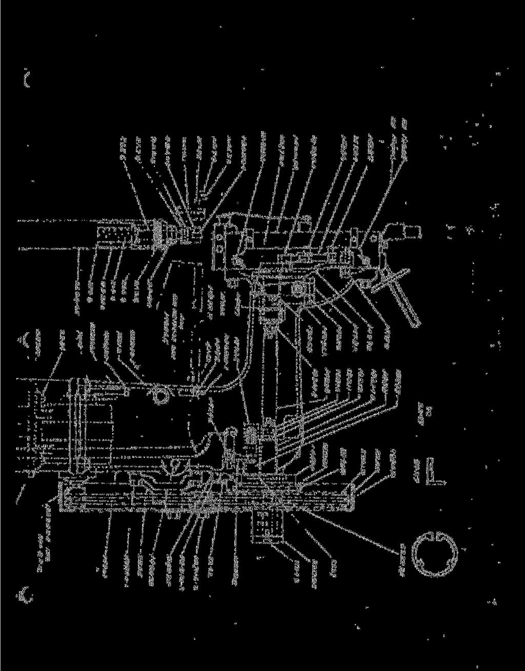
8 t. COMPONENT PARTS 5 OF THE Q I5D BOSTON WIRE STITCHER EADS TRADE MARK BOSTITCH REG. TJ. S. PAT. OFF. BOSTON WIRE STITCHER COMPANY EAST GREENWICH, R. I.

9 15001 ^ B 15018A 15283A FOR SHAFT I5257A I9283A FOR SHAFT I930IA I5283A FOR SHAFT I5257A 19283A FOR SHAFT I930IA A BOSTITCH LINKS IN PARALLEL POSITION. BOSTON WIRE STITCHER CO. LINKS IN RIGHT ANCLE POSITION. COMPONENT PARTS OF 15 HEAD

10 15155 I5094B I5046A I5097B I9283A FOR SHAFT 1930 I5283A-- FOR SHAFT I5257A QJ _ I9283A-. FOR SHAFT I930IA I5283A FOR SHAFT 1525' I5053A I5066A BOSTITCH L1KJKS 1M PARALLEL POSITION! BOSTON WIRE STITCHER CO. COMPONENT PARTS OF LINKS IN RIGHT ANGLE POSITION 5 D-HEAD

11 PARTS FOR NO. 15 HEAD ONLY SEE NO. 15 HEAD CHART BOnnet A Driving Slide Driving Slide Swivel Oper. Pin Swivel Operating Lever Swivel Operating Lever Stud Swivel Operating Lever Stop Swivel Operating Lever Stop Screw A Swivel Operating Spring A Face Plate - Ribbon and Hybar Wire A Wire Cutter Operating Slide A Face Plate - Round Wire A Tension Roll Spring Rod.75 PARTS FOR NO. 15D HEAD ONLY SEE NO. 15D CHART 15001B Bonnet 15113A Wire Cutter Operating Slide 15135A Face Plate - Ribbon and Hybar Wire 19017A Driving Slide Driving Slide Swivel Oper. Pin 19078A Swivel Operating Lever Swivel Operating Lever Stud Swivel Operating Lever Hub 19084A Swivel Operating Spring 19135A Face Plate - Round Wire 19147A Tension Roll Spring Rod Tension Roll Spring Rod Guide 45.00

12 PARTS FOR BOSTON WIRE STITCHER HEADS NO. 15 AND NO. 15D 06 Adjusting Screw Binder 530 Finger Guard 5037 Driver Retaining Spring Rivet 5062 Tension Roll Spring Eod Retainer 5160 Driver Release Pin 7155 Spool Stud 7180 Tension Roll Spring 7224 Wire Cutter Slide Friction Spring 7232 Swivel Hook 7235 Swivel Hook Pivot Pin 7234 Swivel Kook Spring 9010 Driver Retaining Spring 9044 Swivel Holder Clanp Screw 9057 Swivel Oper. Lever Stud Screw Bonnet Screw Driver - round wire Driver - ribbon wire 15012H Driver - Hybar wire 15015A Driver Bar 15022A Bender Bar - round wire 15023A Bender Bar - ribbon wire 15023HA Bender Bar - Kybar wire Bender Slide Bender Slide Spring Bender Slide Spring Plunger Bender Slide Connection Pin Grip - Ribbon Wire 15032A Grip Holder Grip Holder Stud.5034A Grip Retaining Spring Grip Spring Grip Spring Pin Grip Block - Ribbon Wire Grip Block - Round Wire Grip Block Screw Grip Release Slide 15046A Grip Release Lever 1504S Grip Release Lever Pivot 15055A Supporter Supporter Pivot Pin Supporter Guide Pin Supporter Spring Supporter Spring Plunger Supporter Guide Plate Supporter Guide Plate Screw 15056A Swivel - Ribbon Wire Swivel Wire Retainer 15070A Swivel - Hybar Wire Swivel Holder 15073A Swivel Holder Clamp Swivel Holder Guard Swivel Holder Guard Screw Face Plate Adj. Screw Face Plate Adj. Screw Nut Face Plate Clip B Face Plate Clio Screw Face Plate Clip Spring B Face Plate Adj". Slide Face Plate Adj. Slide Pin Stationary Wire Cutter - Hound Y7ire Stationary Wire Cutter - P.ibbon Wire Stationary Wire Cutter Screw Sliding Wire Cutter Wire Cutter Holder Wire Cutter Lock Pin Wire Cutter Lock Pin Spring Wire Cutter Lock Pin Spring Screw Wire Cutter Slide Friction Wire Straightener Roll Clip Wire Straightener Roll Clip Rivet Wire Straightener Roll Clip Spacer Wire Straightener Eccentric Block Ribbon Wire Tension Roll Block - Ribbon Wire A Wire Guide Spring - Round V. : ire A Wire Guide Spring - Ribbon Wire Wire Guide Spring Bracket Wire Guide Spring Bracket Screw Wire Guide Spring Bracket Adj. Screw Spool Stud Friction Disc Spool Stud Bracket Spool Stud Bracket Screw Parallel Slide Extension Parallel Slide Extension Screw A Bender Link Driver Link Bender Link Connection Pin Driver Link Connection Pin Driver - 20 x 24 Wire A Bender Bar - 20 x 24 Wire A S'.vivel - Round Wire Finger Guard Screw Wire Straightener Roll Wire Straightener Roll Stud A Wire Straightener Eccentric Wire Straightener Eccentric Block Round Wire Wire Straightener Eccentric Clip Rivet Wire Straightener Eccentric Clip 7.50 Spacer Tension Roll Block A Bender Link o
Head Serial Number : Date Purchased : Where Installed: (make/model of machine) 26/26D Stitcher Head OPERATION AND MAINTENANCE MANUAL
 26/26D Stitcher Head OPERATION AND MAINTENANCE MANUAL") DELUXE STITCHER C O M P A N Y I N C. Head Serial Number : Date Purchased : Where Installed: (make/model of machine) 26/26D Stitcher Head OPERATION AND MAINTENANCE MANUAL Wire Sizes: 21-28 Ga. Round and
DELUXE STITCHER C O M P A N Y I N C. Head Serial Number : Date Purchased : Where Installed: (make/model of machine) 26/26D Stitcher Head OPERATION AND MAINTENANCE MANUAL Wire Sizes: 21-28 Ga. Round and
Machine Serial Number : Head Serial Number : Date Purchased : #7/ 7AW Stitchers OPERATION AND MAINTENANCE MANUAL
 DELUXE STITCHER C O M P A N Y I N C. Machine Serial Number : Head Serial Number : Date Purchased : #7/ 7AW Stitchers OPERATION AND MAINTENANCE MANUAL 7 Series Stitchers...Electric Clutch 7AW Stitcher w/motor...115v
Heavy Duty Miniature Quick-Change Applicator (End-Feed Type) with Mechanical or Air-Feed Systems
 with Mechanical or Air-Feed Systems") Heavy Duty Miniature Quick-Change Applicator (End-Feed Type) with Mechanical or Air-Feed Systems Instruction Sheet 408-8039 02 JUN 16 Rev G Ram Post Wire Disc Insulation Disc Insulation Crimper Stripper
Heavy Duty Miniature Quick-Change Applicator (End-Feed Type) with Mechanical or Air-Feed Systems Instruction Sheet 408-8039 02 JUN 16 Rev G Ram Post Wire Disc Insulation Disc Insulation Crimper Stripper
Where Installed: (make/model of machine) G5 Stitcher Head OPERATION AND MAINTENANCE MANUAL
 G5 Stitcher Head OPERATION AND MAINTENANCE MANUAL") DELUXE STITCHER COMPANY INC. solving your wire stitching needs for 125 years... Head Serial Number : Date Purchased : Where Installed: (make/model of machine) G5 Stitcher Head OPERATION AND MAINTENANCE
DELUXE STITCHER COMPANY INC. solving your wire stitching needs for 125 years... Head Serial Number : Date Purchased : Where Installed: (make/model of machine) G5 Stitcher Head OPERATION AND MAINTENANCE
Heavy Duty Miniature Quick-Change Applicator (Side-Feed Type) with Mechanical or Air Feed Systems
 with Mechanical or Air Feed Systems") Heavy Duty Miniature Quick-Change Applicator (Side-Feed Type) with Mechanical or Air Feed Systems Instruction Sheet 408-8040 30 NOV 17 Rev H Ram Assembly Ram Post Locking Screw Stock Drag Drag Release
Heavy Duty Miniature Quick-Change Applicator (Side-Feed Type) with Mechanical or Air Feed Systems Instruction Sheet 408-8040 30 NOV 17 Rev H Ram Assembly Ram Post Locking Screw Stock Drag Drag Release
StitchMaster HP OPERATION AND MAINTENANCE MANUAL. SMHP-A25...StitchMaster V...25 Wire SMHP-A StitchMaster V...
 DELUXE STITCHER Machine Model : Serial Number : Head Serial Number : Date Purchased /Installed : C O M P A N Y I N C. solving your wire stitching needs for 125 years... ISP Stitching & Bindery Products
Machine Serial Number : Head Serial Number : Date Purchased : Model M19 Stitchers OPERATION AND MAINTENANCE MANUAL
 DELUXE STITCHER COMPANY INC. solving your wire stitching needs for 125 years... Machine Serial Number : Head Serial Number : Date Purchased : Model M19 Stitchers OPERATION AND MAINTENANCE MANUAL M19-AST
Tech Note Truck 14 & 15.5 Twin Plate Cast Iron Type Installation Guidelines
 1. (14 & 15.5 ) Check condition of the flywheel. Grind to resurface or replace flywheel. Surface MUST BE machined or premature clutch failure can occur. Flywheel depth must be 2.938 (74.62mm) for 14 (350mm)
Mitre Band Saw. Installation and Operating Instructions Note: Not all saw parts are shown in this booklet. Replaceable Aluminum Saw Table
 P ARTS C ATALOG 2G PARTS CATALOG Drive Wheel End Pulley Box Speed Reducer M FG. COMPANY, INC. Mitre Band Saw Installation and Operating Instructions Note: Not all saw parts are shown in this booklet Motor
GRSM17 Pneumatic Center Punch Tool Owner s Manual and Operating Instructions
 Owner s Manual and Operating Instructions Table of Contents Page Information 2 Safety Guidelines and Warranty 3 Overview and Installation 4 Air System Requirements 5 Setting Controls 6 Installing Clamps
Maintenance and Repair
 Maintenance and Repair WARNING ALWAYS shut off the engine, remove key from ignition, make sure the engine is cool, and disconnect the spark plug and positive battery terminal from the battery before cleaning,
Before installation these instructions must be fully read and understood
 Before installation these instructions must be fully read and understood Yoke bushing Split gland bushing One-piece body with accessible internals Gland Swing bolts Fully retractable stellite disc Figure
SERVICE BULLETIN REFERENCES 17-1
 SERVICE BULLETIN REFERENCES 17-1 ENGINE TEAR DOWN Engine tear down and assembly is easy if done right. Use the right tools, disassemble in correct order, and remove complete assemblies intact where possible.
CALIFORNIA TRIMMER MOWER MAINTENANCE MANUAL
 CALIFORNIA TRIMMER MOWER MAINTENANCE MANUAL 2 Table of Contents Section 1: General Information Page Handle Assembly Instructions 4 Maintenance All Models 6 Oil Change Procedures All Models 9 Height Adjustment
Installation and Maintenance Instructions JSE1-0128MAEAD Extruder Clutch. World Leader in Modular Torque Limiters
 World Leader in Modular Torque Limiters Installation and Maintenance Instructions JSE1-0128MAEAD Extruder Clutch 1304 Twin Oaks Street Wichita Falls, Texas 76302 (940) 723-7800 Fax: (940) 723-7888 E-mail:
Start Up & Troubleshooting Manual. Resfab Equipment Inc. St Jean Sur Richelieu Website: resfab.com
 Start Up & Troubleshooting Manual Resfab Equipment Inc. 725 Rossiter St Jean Sur Richelieu 1 450 359 0800 Website: resfab.com Yogurt Blender Service Manual Page SECTION 1: Start Up and Repair... 3 thru
CROWERGLIDE AUTOMATIC CLUTCH Instruction Manual
 CROWERGLIDE AUTOMATIC CLUTCH Instruction Manual Crower Cams & Equipment Co., Inc 6180 Business Center Court San Diego, CA. 92154 Phone: 619.661.6477 ext. 148 Fax: 619.690.7846 www.crower.com TABLE OF CONTENTS
Hudson-Essex. Service Manual Supplement. Hudson Cars 750,001 up
 1 9 2 6 Hudson-Essex Service Manual 1927 Supplement Hudson Cars 750,001 up Hudson Rear Axle (Cars numbered 750,001 and upward) Brakes (Cars numbered 750,001 and upward) See page 18 Transmission Group
DELUXE STITCHER. Osako Stitcher Heads
 DELUXE STITCHER C O M P A N Y I N C. Osako Stitcher Heads OSK102M OSK155M OSK138M OSK120A OSK120A-1 042005 OSK131M OSK130M OSK106M-1 OSK105M OSK121M 077009 047001 G20196 OS OSK125M 04200 0 OSK127 OSK119-B
Service Manual. #19 Gearmatic Winch
 Allis Chalmers Service Manual #19 Gearmatic Winch Service Manual THIS IS A MANUAL PRODUCED BY JENSALES INC. WITHOUT THE AUTHORIZATION OF ALLIS CHALMERS OR IT S SUCCESSORS. ALLIS CHALMERS AND IT S SUCCESSORS
ENGINE CLUTCH CONTENTS OF THIS SECTION
 ENGINE CLUTCH 6C-l ENGINE CLUTCH CONTENTS OF THIS SECTION SUBJECT General Description Periodic Service Adjustments on Car Removal of Clutch Inspection of Clutch Parts Installation of Clutch Specifications
Installation and Maintenance Instructions JSE MAEAD Extruder Clutch. World Leader in Modular Torque Limiters
 World Leader in Modular Torque Limiters Installation and Maintenance Instructions JSE.5-0104MAEAD Extruder Clutch 1304 Twin Oaks Street Wichita Falls, Texas 76302 (940) 723-7800 Fax: (940) 723-7888 E-mail:
Installation Manual. Model T675A Engine Brakes. For Mack 6 Cylinder, 2 valve Head ENDT-673, 675, 676 & E6 Series Engines.
 Engine Brakes Installation Manual Model T675A Engine Brakes For Mack 6 Cylinder, 2 valve Head ENDT-673, 675, 676 & E6 Series Engines TecBrake P.O. Box 27822 Houston, Texas 77227 INSTALLATION MANUAL TECBRAKE
Self-Adjust Clutch Installation Guide
 Self-Adjust Clutch Installation Guide 0 STOP! READ CAREFULLY BEFORE INSTALLING CLUTCH This clutch must be installed by a qualified installer. Improper installation or failure to replace or resurface the
1989 Jeep Cherokee. STEERING COLUMN' '1989 STEERING Jeep Steering Columns STEERING COLUMN STEERING Jeep Steering Columns
 STEERING COLUMN 1989 STEERING Jeep Steering Columns DESCRIPTION All models use collapsible steering columns. All columns have integral ignition switch and locking device. Optional tilt wheel is available
(make/model of machine) G8 Stitcher Head OPERATION AND MAINTENANCE MANUAL
 G8 Stitcher Head OPERATION AND MAINTENANCE MANUAL") DELUXE STITCHER Head Serial Number : Date Purchased : Where Installed: (make/model of machine) C O M P A N Y I N C. solving your wire stitching needs for 125 years... G8 Stitcher Head OPERATION AND MAINTENANCE
DELUXE STITCHER Head Serial Number : Date Purchased : Where Installed: (make/model of machine) C O M P A N Y I N C. solving your wire stitching needs for 125 years... G8 Stitcher Head OPERATION AND MAINTENANCE
OLYMPIAN MODEL 740 Operation and Service Manual
 OLYMPIAN MODEL 740 Operation and Service Manual P/N 133911-102 FCI MANUAL P/N 133865-001 Data herein has been verified and validated and believed adequate for the intended use. If the machine or procedures
Valtek Auxiliary Handwheels and Limit Stops
 Valtek Auxiliary s and Limit Stops Table of Contents Page 1 General information 2 Installation 2 Side-mounted handwheels, size 25 and 50 (linear actuators) 3 Side-mounted handwheels, size 100 and 200 (linear
Duplex Box Stitchers equipped with Wrap Spring Electric Clutch and. BHD Series Wire Stitcher Head
 IDEAL STITCHER COMPANY Division of W.R. Pabich Mfg. 2323 N. Kno Avenue Chicago, Illinois 60639 Phone: 773-486-4141 Fa: 773-486-4812 Email: wrpabich@sbcglobal.net Duple Bo Stitchers equipped with Wrap Spring
CARD RECORDER MECHANISMS
 ITR Engineering Data Sheet 201 September 1927 CARD RECORDER MECHANISMS Card time recorders are used for registering on a card the time that employees enter and leave the factory. The card and the recorder
E L L I O T T 14M, 18M & 24M. Contents OPERATORS INSTRUCTION HANDBOOK FOR THE HIGH SPEED SHAPING MACHINES MODELS. Also COMPONENT PARTS LIST.
 OPERATORS INSTRUCTION HANDBOOK FOR THE E L L I O T T HIGH SPEED SHAPING MACHINES MODELS 14M, 18M & 24M Also COMPONENT PARTS LIST Contents Page Slinging 2 Examination 2 Cleaning 2 Installation 3 Foundation
CARBONETIC Carbon Clutch operating instructions
 ACROSS USA INC www.carbonetic.net TEL:310-635-3555 CARBONETIC Carbon Clutch operating instructions Thank you very much for your purchase of the CARBONETIC carbon clutch. Please read these instructions
CONTENTS: 5740AH - 40 Ton Air/Hydraulic Shop Press 5750AH - 50 Ton Air/Hydraulic Shop Press OWNER'S MANUAL
 OWNER'S MANUAL CONTENTS: Page 1 Specifications 2 Safety Information and Warranty Information 3 Parts List 4-6 Assembly Instructions 7 Pump and Ram Assembly Instructions 8 Procedure for Bleeding Air 9 Pump
Crestline Altra Series TM Dampener. Installation Instructions. Heidelberg GTO. X /98 Rev-A
 Crestline Altra Series TM Dampener Installation Instructions Heidelberg GTO X88-63 7/98 Rev-A GENERAL INFORMATION ATTENTION CRESTLINE ALTRA SERIES TM DAMPENER OWNER! Accel Graphic Systems provides parts
ASSEMBLY INSTRUCTION MANUAL
 ASSEMBLY INSTRUCTION MANUAL 500, 600, 660, 5010, 6010 & 6610 Snowblower Electric Spout Rotation Kit Instructions 122013 P4710 Electric spout rotation kit is to be used in place of a hydraulic or hand
Rotary Pak-Tyers. Thanks, again. Felins USA, Inc. Phone: Fax: West Parkland Court Milwaukee, Wisconsin 53223
 Rotary Pak-Tyers Thank you very much for choosing this Felins Rotary Pak-Tyer tying machine. This tying machine is designed and manufactured to tie many articles with string, poly tape or elastic materials
TC20 Chain Driven Power Take-Off Overhaul Instructions
 TC20 Chain Driven Power Take-Off Overhaul Instructions Table of Contents Section Page Introduction 4 Ordering Repair Parts 4 General Information 5 Special Tools 6 Disassembly See Page 2 Reassembly See
GROUP 6 CLUTCH CONTENTS SPECIFICATIONS
 GROUP 6 CLUTCH CONTENTS Page CLUTCH 6-1 Specifications.... 1 Transmission Main Drive Pinion Pilot Bushing... 5 Special Tools. 1 Clutch Release Bearing 6 Torque Reference 1 Torque Shaft and Bearings...
SHIP TO MANUFACTURING STITCHERS FOR EVERY STAPLING NEED SINCE 1933
 IDL STITCHER COMPANY DIVISION OF W.R. PABICH MFG. CO., INC. 2323 NORTH KNO AVE CHICAGO, ILLINOIS 60639-3484 (773) 486-4141 FA (773) 486-4812 E-Mail: wrpabich@sbcglobal.net IDL - AMERICAN - LATHAM - MONITOR
1967 (Late) and 1968 CORVETTE TELESCOPING STEERING COLUMN DISASSEMBLY & REPAIR INSTRUCTIONS - PAPER #1
 and 1968 CORVETTE TELESCOPING STEERING COLUMN DISASSEMBLY & REPAIR INSTRUCTIONS - PAPER #1") Last Revision: 03SE2012 1967 (Late) and 1968 CORVETTE TELESCOPING STEERING COLUMN DISASSEMBLY & REPAIR INSTRUCTIONS - PAPER #1 Disassembly and Repair Instructions Addressed in this Paper Difficulty Page
Last Revision: 03SE2012 1967 (Late) and 1968 CORVETTE TELESCOPING STEERING COLUMN DISASSEMBLY & REPAIR INSTRUCTIONS - PAPER #1 Disassembly and Repair Instructions Addressed in this Paper Difficulty Page
INSTRUCTION MANUAL & PARTS BOOK. Vibratory Screed
 INSTRUCTION MANUAL & PARTS BOOK Vibratory Screed 200 COMMERCE DRIVE, FREEHOLD, NEW JERSEY, USA, 07728, 732-566-5400 FAX 732-5444 Doc. # OI-M09201 Current Rev. 07 Revised: 11/2013 Orig. Rel.: 06/2014 SAFETY
Marine Engineering Exam Resource Review of Couplings
 1. What are rigid couplings used for? Used to join drive shafts together. True alignment and rigidity are required. Example Drive shafts and production lines, bridge cranes, solid shaft that needs to be
Edition Manual Chapter Page Workshop Manual, Stiga Park 5 Belts 11
 2008-05-19 Workshop Manual, Stiga Park 5 Belts 11 Pro 20 1. Dismantle the belts A and B as described above. 2. Block up the rear frame and remove the right rear wheel. Clean carefully the insex hole in
OPERATION AND MAINTENANCE MANUAL
 WREN IBT SERIES HYDRAULIC TORQUE WRENCHES IBT SQUARE DRIVE SERIES OPERATION AND MAINTENANCE MANUAL FOR WREN Products: POINT 75, 1IBT, 3IBT, 5IBT, 8IBT, 10IBT, 20IBT, 25IBT, 35IBT, 50IBT SQUARE DRIVE HYDRAULIC
Section X STEERING DATA AND SPECIFICATIONS. 21 degrees 45 minutes -f- or 1 degree (inner wheel when outer wheel is 20 degrees)
") 76 Section X DATA AND SPECIFICATIONS MODELS MC-1 MG-2 MC-3 MY-1 Steering Type Manual Power Worm and Three Tooth Roller None None None Rack and Gear Sector, Recirculating Ball Nut Ratio Manual 20.4... Power
76 Section X DATA AND SPECIFICATIONS MODELS MC-1 MG-2 MC-3 MY-1 Steering Type Manual Power Worm and Three Tooth Roller None None None Rack and Gear Sector, Recirculating Ball Nut Ratio Manual 20.4... Power
Maintenance Instructions
 General Note These instructions contain information common to more than one model of Bevel Gear Drive. To simplify reading, similar models have been grouped as follows: GROUP 1 Models 11, 0, 1,, (illustrated),,
Installation and Maintenance Instructions JSE2-0241MAEAD Extruder Clutch. World Leader in Modular Torque Limiters
 World Leader in Modular Torque Limiters Installation and Maintenance Instructions JSE2-0241MAEAD Extruder Clutch 1304 Twin Oaks Street Wichita Falls, Texas 76302 (940) 723-7800 Fax: (940) 723-7888 E-mail:
Operation and Maintenance Manual for BS and BH Hydraulic Torque Wrenches
 BOLTORQ Operation and Maintenance Manual for BS and BH Hydraulic Torque Wrenches It is operating manual of BS series and BH series wrenches, please read carefully and follow the instructions. Warning and
Installation Instructions
 Installation Instructions Rear Disc Brake Conversion Kit Item # RC4001, RC4001X Applications: Mopar 7.25, 8.25, 9.25 Axles Thank you for choosing Leed Brakes for your automotive product needs. Before you
Tooling Assistance Center
 Safeguards are designed into this application equipment to protect operators and maintenance personnel from most hazards during equipment operation. However, certain safety precautions must be taken by
OPERATIONS MANUAL LEVER CHAIN HOIST
 OPERATIONS MANUAL LEVER CHAIN HOIST IMPORTANT SAFETY INFORMATION Please read, understand and follow all safety information contained in these instructions prior to the use of this hoist. Retain these instructions
Agri-Fab OWNERS MANUAL. Model No " ROUGH CUT TRAILMOWER. CAUTION: Read Rules for Safe Operation and Instructions Carefully
 Agri-Fab OWNERS MANUAL Model No. 45-0362 CAUTION: Read Rules for Safe Operation and Instructions Carefully Safety Assembly Operation Maintenance Parts 42" ROUGH CUT TRAILMOWER NOTE: Your mower deck will
Installation Manual. Model T680A/B Engine Brakes. For Mack 6 Cylinder, 4 Valve Head E6 and E7 Series Engines. Engine Brakes
 Engine Brakes Installation Manual Model T680A/B Engine Brakes For Mack 6 Cylinder, 4 Valve Head E6 and E7 Series Engines TecBrake P.O. Box 27822 Houston, Texas 77227 INSTALLATION MANUAL TECBRAKE T680A
SERIES G3DB/AG3DB ELEVATOR
 TM INSTRUCTIONS AND PARTS LIST SERIES G3DB/AG3DB ELEVATOR WARNING This manual, and GENERAL INSTRUCTIONS MANUAL, CA-1, should be read thoroughly prior to pump installation, operation or maintenance. SRM00059
Agri-Fab OWNERS MANUAL. Model No " ROUGH CUT TRAILMOWER. CAUTION: Read Rules for Safe Operation and Instructions Carefully
 Agri-Fab OWNERS MANUAL Model No. 45-03071 45-0361 CAUTION: Read Rules for Safe Operation and Instructions Carefully Safety Assembly Operation Maintenance Parts 42" ROUGH CUT TRAILMOWER the fastest way
FX140 & FX140R Skidding Winch Parts Manual
 EMB Manufacturing Inc. 4144 Boomer Line St. Clements, On N0B 2M0 Canada Ph: (519) 699-9283 Fax: (519) 699-4146 www.wallensteinequipment.com FX140 & FX140R Skidding Winch Parts Manual S/N 514094 & After
Clutch Installation Guide
 Clutch Installation Guide 0 STOP! READ CAREFULLY BEFORE INSTALLING CLUTCH This clutch must be installed by a qualified installer. Improper installation or failure to replace or resurface the flywheel,
Installation Instructions
 Equipment Required: Wrenches: 9/16, 3/4, 1-1/8 Drill Bits: 11/32 Torque Wrench capable of reading 260 ft-lbs. Installation Instructions IN DEALERS: Please give these instructions to your customer. Do Not
Wheeler Mfg. Div Rex Intl USA Inc Jefferson Road Ashtabula, OH Tel: Fax:
 Wheeler Mfg. Div Rex Intl USA Inc. 3744 Jefferson Road Ashtabula, OH 44004 Tel: 800-321-7950 Fax: 440-992-2925 wheeler@wheelerrex.com www.wheelerrex.com Some Operating Hints...... 2 The 68115 features
MECHANICAL INSTRUCTIONS NOISELESS PORTABLE TYPEWRITER. RcminoTon rard inc. 465 Washington Street BUFFALO, NEW YORK. SM-SO Printed In U.S.A.
 MECHANICAL INSTRUCTIONS NOISELESS PORTABLE TYPEWRITER RcminoTon rard inc 465 Washington Street BUFFALO, NEW YORK SM-SO Printed In U.S.A. INDEX TO SUBJECTS PLATE NAME OF SUBJECT PAGE PAGE TEXT CYLINDER
Fig.01 Fig.02 Fig.03. Disassembly & Reassembly Instructions SBV-HP - Page 3
 M12A14 WITH FLOATING BACKSEAT 3 Fig.01 Fig.02 Fig.03 Disassembly & Reassembly Instructions SBV-HP - Page 3 M12A14 WITH FLOATING BACKSEAT 3 1. Caution, before any attempt is made to disassemble, verify
Self-Recovery Winch WARNING. General Safety Precautions
 1 Self-Recovery Winch Thank you for purchasing a Winch. This manual covers operation and maintenance of the winch. All information in this publication is based on the latest production information available
Provided by: Operating, Maintenance & Parts Manual
 Provided by: www.hoistsdirect.com TB681.qxd 11/29/2004 3:04 PM Page 1 Operating, Maintenance & Parts Manual TB603 Manually Lever Operated Chain Hoist 1100 POUNDS MAXIMUM CAPACITY (500 kg) Follow all instructions
SUSPENSION 2-1 SUSPENSION TABLE OF CONTENTS
 DN SUSPENSION 2-1 SUSPENSION TABLE OF CONTENTS page ALIGNMENT... 1 FRONT SUSPENSION - 4x2... 6 page FRONT SUSPENSION - 4x4... 14 REAR SUSPENSION... 23 ALIGNMENT TABLE OF CONTENTS page AND OPERATION WHEEL
SERVICE AND REPAIR PARTS NEMA SIZE 5, SINGLE POLE, NORMALLY OPEN, P/N SERIES NEMA SIZE 5A, SINGLE POLE, NORMALLY OPEN, P/N SERIES
 Hubbell Industrial Controls, Inc. SERVICE AND REPAIR PARTS NEMA SIZE 5, SINGLE POLE, NORMALLY OPEN, P/N 59495 SERIES NEMA SIZE 5A, SINGLE POLE, NORMALLY OPEN, P/N 59675 SERIES Instructions 5210 Publication
SD Bendix Manual Slack Adjusters DESCRIPTION ADJUSTING MECHANISM OPERATION
 SD-05-1200 Bendix Manual Slack Adjusters WORM SHAFT (LOCK SCREW) FIGURE 1 - POSITIVE LOCK TYPE SLACK ADJUSTER DESCRIPTION In an s-cam type foundation brake, the final link between the pneumatic system
CHAINGUARD REGAL ST COLOR
 DESOTO/ REGAL HAULER PARTS LIST Item Part # Description QTY Item Part # Description QTY 1 11871 REFLECTOR KIT TRIKE 1 32 11764 FENDER BRACE 24" MWT 1 2 12199 SCREW #14 x 3/4 4 33 12176 NUT5/16-24 HEX 2
Lift N Go [Model 210] Electric Carrier For use with power chairs & scooters Installation Guide & Owners Manual
![Lift N Go [Model 210] Electric Carrier For use with power chairs & scooters Installation Guide & Owners Manual](/thumbs/74/70316262.jpg "Lift N Go [Model 210] Electric Carrier For use with power chairs & scooters Installation Guide & Owners Manual") 203 Matzinger Road Toledo, OH 43612 Phone: 1-800-541-3213 Fax: (419) 478-4425 www.wheelchaircarrier.com E-mail: admin@wheelchaircarrier.com Lift N Go [Model 210] Electric Carrier For use with power chairs
203 Matzinger Road Toledo, OH 43612 Phone: 1-800-541-3213 Fax: (419) 478-4425 www.wheelchaircarrier.com E-mail: admin@wheelchaircarrier.com Lift N Go [Model 210] Electric Carrier For use with power chairs
CLUTCH CONTENTS SERVICE DIAGNOSIS. (a) Worn or damaged disc assembly. (b) Grease or oil on disc facings. (c) Improperly adjusted cover assembly.
 Worn or damaged disc assembly. (b) Grease or oil on disc facings. (c) Improperly adjusted cover assembly.") CLUTCH CONTENTS -GROUP 6 Page CLUTCH HOUSING ALIGNMENT... 6 CLUTCH PEDAL FREE PLAY 1 CLUTCH RELEASE BEARING 5 CLUTCH RELEASE FORK... 5 CLUTCH SERVICING 2 PILOT BUSHING CRANKSHAFT TO TRANSMISSION DRIVE
CLUTCH CONTENTS -GROUP 6 Page CLUTCH HOUSING ALIGNMENT... 6 CLUTCH PEDAL FREE PLAY 1 CLUTCH RELEASE BEARING 5 CLUTCH RELEASE FORK... 5 CLUTCH SERVICING 2 PILOT BUSHING CRANKSHAFT TO TRANSMISSION DRIVE
This file is available for free download at
 This file is available for free download at http://www.iluvmyrx7.com This file is fully text-searchable select Edit and Find and type in what you re looking for. This file is intended more for online viewing
INSTALLATION, OPERATION AND MAINTENANCE INSTRUCTIONS
 INSTALLATION, OPERATION AND MAINTENANCE INSTRUCTIONS Contents Section 1. General Observations... 2 2. Operation... 4 3. Control During Operation... 5 4. Trouble Shooting... 6 5. Maintenance... 7 Please
Adjustments manual for: Gear Drive, ETS Gear Drive, Walk Hydro, ETS Walk Hydro, Mini Rider, Large Rider Gen 2
 For Husqvarna Parts Call 66-678-96 or 66-56-98 Adjustments manual for: Gear Drive, ETS Gear Drive, Walk Hydro, ETS Walk Hydro, Mini Rider, Large Rider Gen MANUAL NO. 5957 REV. (//) For Husqvarna Parts
920 Remote Control Switches
 920 Remote Control Switches REMOTE CONTROL SWITCHES Service Bulletin This service bulletin for ASCO 920 Remote Control Switches explains how to replace the main s, operator coil, control s, and how to
CHAINGUARD REGAL ST COLOR
 DESOTO/ REGAL HAULER PARTS LIST Item Part # Description QTY Item Part # Description QTY 1 11871 REFLECTOR KIT TRIKE 1 32 11762 FENDER BRACE 20" MWT 1 2 12199 SCREW #14 x 3/4 4 11764 FENDER BRACE 24" MWT
SL-6 & SL-6A. I UNION SWITCH & SIGNAL l[ml 645 Russell Street Batesburg, SC Service Manual Field and Shop Maintenance
 I UNION SWITCH & SIGNAL l[ml 645 Russell Street Batesburg, SC 29006 Service Manual 3011 SL-6 & SL-6A Outlying Switch Lock Field and Shop Maintenance April, 1979 A-79-500-1496-3 1979, Union Switch & Signal
Fisher 657 Diaphragm Actuator Sizes and 87
 Instruction Manual 657 Actuator (30-70 and 87) Fisher 657 Diaphragm Actuator Sizes 30 70 and 87 Contents Introduction... 1 Scope of Manual... 1 Description... 2 Specifications... 2 Installation... 3 Mounting
PRODUCT INFORMATION BULLETIN #3365 DIGITAL MOTOR CONTROL PLATTER SYSTEMS For Serial Number and After
 PRODUCT INFORMATION BULLETIN #3365 DIGITAL MOTOR CONTROL PLATTER SYSTEMS For Serial Number 28640996 and After Record Platter System Identification Numbers Here: Model # Serial # Table of Contents Program
CABINET REEL OPERATING INSTRUCTIONS
 CABINET REEL OPERATING INSTRUCTIONS MODELS 15, 25, 40 & 60 SERIES RAPID-AIR CORPORATION 4601 KISHWAUKEE ST. ROCKFORD, IL 61109-2925 Phone: (815) 397-2578 Fax: (815) 398-3887 Web Site: www.rapidair.com
Installation Instructions
 Installation Instructions Rear Disc Brake Conversion Kit Item # RC2001, RC2001X Applications: Mopar 8-3/4 & 9-3/4 Rear Axles Thank you for choosing Leed Brakes for your automotive product needs. Before
Sisu S-Cam Drum Brakes
 Sisu S-Cam Drum Brakes (For hub reduction rear axles since 1992) Maintenance Manual Sisu Axles, Inc. Autotehtaantie 1 P.O. Box 189 FIN-13101 Hämeenlinna Finland Phone int + 358 204 55 2999 Fax int + 358
AUTOMATIC CLUTCH Models
 AUTOMATIC CLUTCH 1940 Models Source of this material is from 1940 Series, Issue 4, January 1940 Hudson Service Magazine AUTOMATIC CLUTCH 1940 MODELS The automatic clutch installation and adjustment procedure
62 Deck Idler Kit High Speed
 Part No. 00 FORM NO. -899 6 Deck Idler Kit High Speed For Model 70 Serial No. 99000 to 99000 For Model 7 Serial No. 9900 to 99000 INSTALLATION INSTRUCTIONS Loose Parts Note: Use the chart below to identify
Contents. Section 5: Adjustments Ball Detect Adjustment Transport Band Tension Adjustment
 Contents Section 5: Adjustments... 5-3 1. Ball Detect Adjustment... 5-3 2. Transport Band Tension Adjustment... 5-5 3. Transport Band Drive Belt Tension Adjustment... 5-7 4. Ball Cushion Adjustment...
20 TONNE HYDRAULIC PRESS MODEL NO: CSA20FBT
 20 TONNE HYDRAULIC PRESS MODEL NO: CSA20FBT PART NO: 7614058 OPERATION & MAINTENANCE INSTRUCTIONS WARNING: Read these instructions before using the press GC0516 INTRODUCTION Thank you for purchasing this
MailStar Maintenance and Adjustment March 2002
 MailStar Maintenance and Adjustment March 2002 The MailStar bicycle incorporates many new features to ease maintenance and improve handling and performance. The majority of components are similar to those
Installation Instructions Capacity 10,000 lbs. (100 Series Lift)
") Installation Instructions Capacity 10,000 lbs. (100 Series Lift) IMPORTANT Reference ANSI/ALI ALIS, Safety Requirements for Installation and Service of Automotive Lifts before installing lift. OPERATING
Installation Instructions Capacity 10,000 lbs. (100 Series Lift) IMPORTANT Reference ANSI/ALI ALIS, Safety Requirements for Installation and Service of Automotive Lifts before installing lift. OPERATING
37A- S/N 350,000 Up. Turbine Drive Water-Reels. Engine Drive Slurry-Reels T37A E37A. Parts Manual. Serial No. 350, ,999
 37A- S/N 350,000 Up Turbine Drive Water-Reels Engine Drive Slurry-Reels T37A E37A Parts Manual Serial No. 350,000-359,999 700 S. Schrader Ave. Havana, Illinois 62644 Phone: 309-543-4425 Fax: 309-543-4945
GftOUP 4 PARKING BHAKE
 PARKING BRAKE 4-1 GftOUP 4 PARKING BHAKE CONTENTS Page Data and Specifications... 1 External Contracting Type Parking Brake...... 2 Parking Brake Band Lining 3 Parking Brake Internal Expanding Type 5 Parking
Last Revision: 07SE2009
 Last Revision: 07SE2009 1967 (Late) and 1968 CORVETTE STANDARD (NON-ADJUSTABLE) STEERING COLUMN DISASSEMBLY & REPAIR INSTRUCTIONS PAPER #1 Disassembly and Repair Instructions Addressed in this Paper Difficulty
40 North 2 nd Street Stroudsburg, PA USA
 40 North 2 nd Street Stroudsburg, PA 18360 USA 570-421-6221 Marvel Aircraft Propeller Balancer Horizontal Method - Suspension Type Bulletin No. 77 Section I Description 1 1. GENERAL 1 2. The Model 7A1000
OPERATION MANUAL Electric Wire Wrapper TDWW501B
 OPERATION MANUAL Electric Wire Wrapper TDWW501B 4270 Airborn Drive Addison, Texas 75001 USA t. 972.248.1999 f. 972.248.1991 info@startinternational.com www.startinternational.com INTRODUCTION Thank you
Table of Contents Visual Inspection and Neutralizing... 3 Disassembly
 1 Table of Contents Visual Inspection and Neutralizing... 3 Disassembly... 3... 4... 4 Cleaning... 4 Inspection... 4 Reconditioning of Valve Seats... 5 Lapping Procedures... 5 Lapping Blocks... 5 Lapping
DRIVE AXLE Volvo 960 DESCRIPTION & OPERATION AXLE IDENTIFICATION DRIVE AXLES Volvo Differentials & Axle Shafts
 DRIVE AXLE 1994 Volvo 960 1994 DRIVE AXLES Volvo Differentials & Axle Shafts 960 DESCRIPTION & OPERATION All 960 station wagon models use type 1041 rear axle assembly. All 960 4-door models use type 1045
Final Assembly Instructions: Bikes with Threadless Headsets
 Final Assembly Instructions: Bikes with Threadless Headsets Thank you for buying your new bicycle from L.L.Bean. Read these instructions carefully before beginning the final assembly. Prior to shipping,
Ford C4 and C6 Floor Mount Automatic Transmission Shifter Installation Instructions
 Ford C4 and C6 Mount Automatic Transmission Shifter Installation Instructions Building American Quality With A Lifetime Warranty! TOLL FREE 1-877-469-7440 tech@lokar.com www.lokar.com Ford C4 and C6 Mount
SERVICE AND REPAIR PARTS NEMA SIZE 3, SINGLE POLE, NORMALLY OPEN, P/N SERIES NEMA SIZE 4, SINGLE POLE, NORMALLY OPEN, P/N SERIES
 Hubbell Industrial Controls, Inc. Instructions 5210 SERVICE AND REPAIR PARTS NEMA SIZE 3, SINGLE POLE, NORMALLY OPEN, P/N 59364 SERIES NEMA SIZE 4, SINGLE POLE, NORMALLY OPEN, P/N 59345 SERIES Publication
Rheometer Calibration Fixture Instruction Manual Model 280 & 286
 Rheometer Calibration Fixture Instruction Manual Model 280 & 286 Instruction Manual Part No. 204210 Revision B Copyright 2009 Fann Instrument Company Houston, Texas, U.S.A. All rights reserved. No part
WARNING Carefully Read These Instructions Before Use
 DO NOT RETURN THIS SPRAYER TO STORE Call: 1-800-950-4458 Backpack Sprayer Use and Care Manual Manufactured for Northern Tool + Equipment Co., Inc. WARNING Carefully Read These Instructions Before Use Model
DB4604 GMR-SD and GMR40-SD Disc Brake Caliper - Spring Applied, Air Released
 DB464 GMR-SD and GMR4-SD Disc Brake Caliper - Spring Applied, Air Released Nominal dimensions given. For specific dimensions please contact Twiflex Limited. For GMR Mk 2 caliper details see DB 364 Air
CONTENTS: Ton Hydraulic Shop Press w/ Winch Ton Hydraulic Shop Press w/ Winch OWNER'S MANUAL
 OWNER'S MANUAL CONTENTS: Page 1 Specifications 2 Safety Information and Warranty Information 3 Parts List 4-8 Assembly Instructions 9 Procedure for Bleeding Air 10 Pump Instructions 11-12 Winch Kit List