|
|
|
- Iris Randall
- 5 years ago
- Views:
Transcription
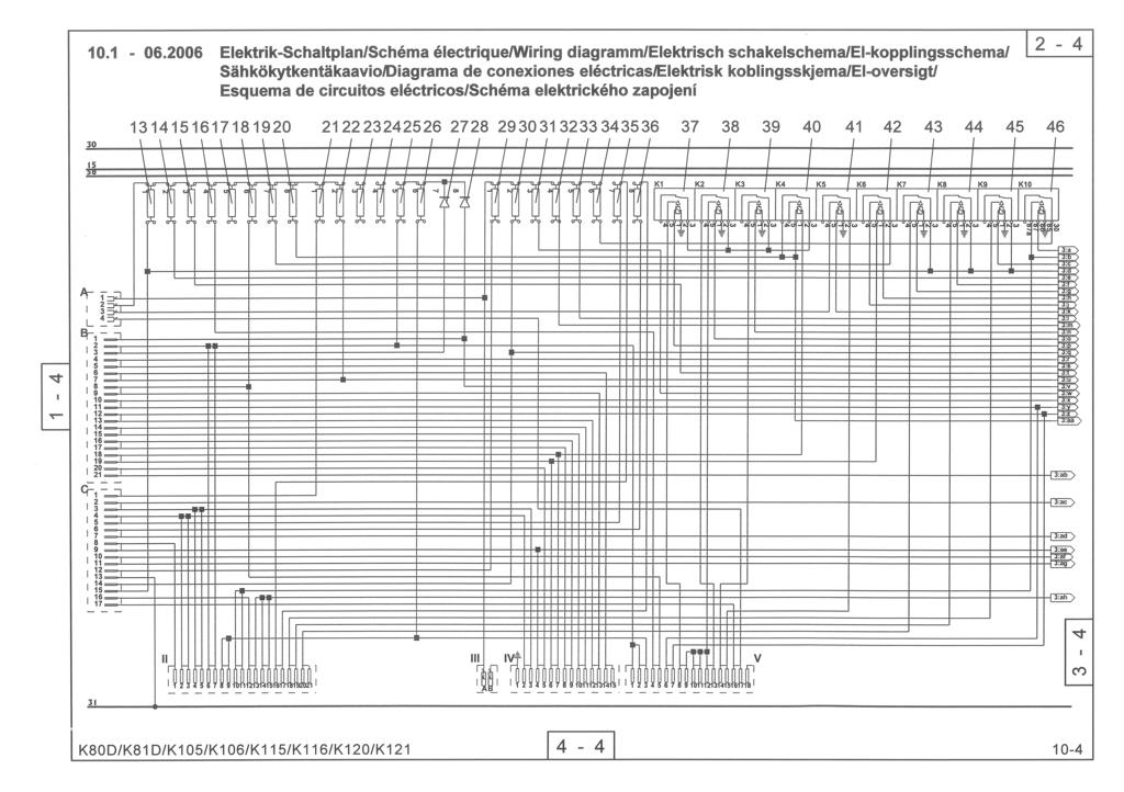
1 Diagrams

2
3

4

5
6 Diagrams Electric wiring diagram Item Designation 01 Indicator lamp assembly 02 Fuel gauge 03 Engine oil temperature gauge 04 RM meter 05 Operating hours meter 06 Actuator: Release of quick-change device (option) 07 Actuator: Rear window wiper/washer 08 Actuator: Road lights 09 Actuator: Hazard flasher 10 Start switch 11 Windshield wiper motor, front 12 Steering column switch K80D/K81D/K105/K106/K115/K116/K120/K
7 10 Diagrams Item Designation 13 Fuse (chapter 4.5/A1) 14 Fuse (chapter 4.5/A2) 15 Fuse (chapter 4.5/A3) (SA) 16 Fuse (chapter 4.5/A4) 17 Sicherung (nicht belegt) 18 Fuse (chapter 4.5/A6) 19 Fuse (chapter 4.5/A7) 20 Fuse (chapter 4.5/A8) 21 Fuse (chapter 4.5/B1) 22 Fuse (chapter 4.5/B2) 23 Fuse (free) 24 Fuse (free) 25 Fuse (chapter 4.5/B5) 26 Fuse (chapter 4.5/B6) 27 Light indicator diode (chapter 4.5/B7) 28 Light indicator diode (chapter 4.5/B8) 29 Fuse (chapter 4.5/C1) 30 Fuse (chapter 4.5/C2) 31 Fuse (chapter 4.5/C3) 32 Fuse (chapter 4.5/C4) 33 Fuse (chapter 4.5/C5) 34 Fuse (chapter 4.5/C6) 35 Fuse (chapter 4.5/C7) 36 Fuse (chapter 4.5/C8) 37 Relay for power adaptation: forward 38 Relay for power adaptation: reverse 39 Relay Alpha max. 40 Traction drive cut-out relay 41 Starter interlock relay 42 Rear window heater relay 43 Relay for auxiliary hydraulics: Close bucket 44 Relay for auxiliary hydraulics: Open bucket 45 Relay for differential lock 46 Relay for working lights 10-4 K80D/K81D/K105/K106/K115/K116/K120/K121
8 Diagrams 10 Item Designation 47 Actuator: Working lights 48 Actuator: Rear window heater 49 Actuator: Lifting device suspension (option): 50 Actuator: Warning beacon (opt.) 51 Actuator: Fan/blower 52 Gear switch (only for fast loaders) 53 2-pole socket 54 Turn signal relay 55 Interval timer 56 Buzzer 57 Radio (option) 58 Multifunction lever 59 Gear switch micro relay 60 Gear switch micro relay 61 Gear shift impulse relay 62 Gear shift timer relay 63 Heater fan motor 64 Air conditioning system (option) 65 Warning beacon (opt.) 66 Wiper motor, rear 67 Cigarette lighter 68 Interior lighting 69 Interior lighting switch 70 Rear window heater 71 Working lights 72 Working lights 73 Working lights 74 Working lights K80D/K81D/K105/K106/K115/K116/K120/K
9 10 Diagrams Item Designation 75 Alternator 76 Starter 77 Battery 78 Battery main switch 79 Fuse (oil cooler) 80 Relay (oil cooler) 81 Oil cooler thermostat 50 / Oil cooler fan motor 83 Brake light switch 84 Valve Alpha max. 85 Direction detection valve 86 Reversing buzzer valve 87 Valve, reverse drive direction 88 Valve, forward drive direction 89 Valve for 2nd gear (only for fast loaders) 90 Valve for 1st gear (only for fast loaders) 91 Hydraulic oil filter switch 92 Dip pipe sensor 93 arking brake switch 94 Window washer motor, rear 95 Windshield washer motor, front 96 License plate illumination (option) 97 Reversing light, left 98 Brake light, left 99 Tail light, left 100 Turn signal, rear left 101 Reversing light, right 102 Brake light, right 103 Tail light, right 104 Turn signal, rear right 105 Valve for auxiliary hydraulics: close bucket 106 Valve for auxiliary hydraulics: open bucket 107 Differential lock valve 108 Combination valve: pipe break protection/lifting device suspension (option) 109 Reservoir valve, lifting device suspension (option) 110 Memory valve, lifting device suspension (option): 111 ressure switch, lifting device suspension (option): 112 Quick-change device release valve 113 Working lights (option) 114 Working lights (option) 115 High beam, left 116 Low beam, left 117 arking light, left 118 Turn signal, front left 119 High beam, right 120 Low beam, right 121 arking light, right 122 Turn signal, front right 123 Signal horn 124 Torque minus adaptation valve 125 Start fuel allowance valve 126 Engine shut-off valve 127 Oil pressure switch 128 Motor oil temperature sensor pole socket (option) NOTE The bold numbers next to the item numbers in the electric wiring diagram are cross references to the respective part in the hydraulic diagram K80D/K81D/K105/K106/K115/K116/K120/K121
10
11 Hydraulikschaltplan/Schéma hydraulique/hydraulisch schakelschema/hydraulic circuit diagram/hydraulikoversigt/lano de conexiones hidráulicas/ Hydraulisk koblingsskjema/hydraulik kopplingsschema/lano de circuitos hidráulicos AL A3 B3 A2 B2 270 bar 300 bar A1 B1 T G3/4" DS6 Y10 A 0,7 l 20 bar B 0,7 l 20 bar Y7 M18x1,5 L 240 M18x1,5 R bar E M14x1,5 B E A DS4 M14x1,5 M14x1,5 M14x1,5 DS3 M10x1 25 Y11 Y3/B1/rot G1/4" A T G1/4" X3/A1/blau G1/4" B G1/4" G1/4" G1/4" G1/4" G1/4" G1/4" G1/4" Y63 Y64 26 T G1/4"G1/4" G1/4" G1/4" G1/4" G1/4" Fahrtrichtung X2/A3/grün Y1/B2/braun 27 Y2/B3/grau X1/A2/schwarz bar 0,7 l G1/4 LS CF EF M12x1,5 LS M18x1,5 M18x1,5 T muem. DS1 2 bar M33x2 M10x1 M42x2 M26x1,5 J1 S1 E1 S2 0,5 bar 10 muem. 0,04 bar 100 muem. 3,0 bar 3 bar M12x1,5 56 cm³/u M22x1,5 R T1 Y1 b a Y2 = 485±10 bar = 485±10 bar Z M10x1 S M12x1,5 G = bar = bar M22x1,5 X TS1 M12x1,5 MB M22x1,5 T2 X1 X2 S MA M12x1,5X X M12x1,5 M33x2 X M12x1,5 11,1 cm³/u X (SAE 3/4") (SAE 3/4") B A TS2 S M22x1,5 34 cm³/u X SAE 1" T B A Y3 U G T SAE 1" M12x1,5 M14x1,5 M18x1,5 X _.. _.. _ 15 Messanschluss Branchement de mesure Gauge part Meetaansluiting Conexión de medición Sonderausstattung En option Optional equipment Wardt niet standaard geleverd Opción K80C/K81C/K100/K101/K110/K111/K120
12 Diagrams Hydraulic diagram (AL 80 und AL 100) Item Designation 01 Unpressurized return line (option) 02 ipe break protection, tilt cylinder (option) 03 Tip cylinder DW 110/50/377/ Locking cylinder DW 40/25/ Auxiliary hydraulics 06 Shut-off valve, quick-change device 07 ipe break protection, lift cylinder (option) 08 Lift cylinder DW 130/80/526/ Lifting device suspension (option) 10 Steering cylinder DW 80/40/395/ Steering unit, 320/160 cm³/rev. 12 Hydraulic gear switch (only for fast loaders) 13 riority valve 14 Hydraulic oil cooler 15 Drive motor A6VM 80 HA 16 Gear-type pump 30 cm³/rev. 17 Drive pump A4VG 56 DA 18 Drive engine: AL 80 - KHD F4L 2011 / 40 kw / 2300 rpm AL KHD F4L 2011 / 43.5 kw / 2300 rpm 19 Combined suction and return flow filter 20 Hydraulic oil tank 21 Electric contamination indicator 22 Main brake cylinder 23 Lamella brake 24 arking brake valve 25 3-way valve 26 Differential lock 27 Control pressure transmitter, auxiliary hydraulics 28 Control pressure transmitter, working hydraulics 29 Shut-off valve, working hydraulics option = Optional equipment K80D/K81D/K105/K106/K115/K116/K120/K
13 Diagrams Hydraulic diagram AL 120 Item Designation 01 Unpressurized return line (option) 02 ipe break protection, tilt cylinder (option) 03 Tip cylinder DW 110/70/448/ Locking cylinder DW 40/25/ Auxiliary hydraulics 06 Shut-off valve, quick-change device 07 ipe break protection, lift cylinder (option) 08 Lift cylinder DW 90/50/598/ way valve 10 Lifting device suspension (option) 11 Steering cylinder DW 80/40/395/ Steering unit, 320/160 cm³/rev. 13 riority valve 14 Hydraulic oil cooler 15 Drive motor A6VM 80 HA 16 Gear-type pump 34 cm³/rev. 17 Drive pump A4VG 56 DA 18 Drive engine: KHD BF4L 2011 / 53,5 kw / 2500 rpm 19 Combined suction and return flow filter 20 Hydraulic oil tank 21 Electric contamination indicator 22 Main brake cylinder 23 Lamella brake 24 arking brake valve 25 Differential lock 26 Control pressure transmitter, auxiliary hydraulics 27 Control pressure transmitter, working hydraulics 28 Shut-off valve, working hydraulics option = Optional equipment K80D/K81D/K105/K106/K115/K116/K120/K
F1050/F1200/S0700/S0900
 Circuit diagrams 1-4 10-3 10.1-06.2010 Elektrik-Schaltplan/Schéma électrique/wiring diagramm/elektrisch schakelschema/sähkökytkentäkaavio/ Variante 1 Kopplingsschema-elektrik/Schemat instalacji elektrycznej/schéma
AR12 & AR20 Wiring diagram (multifunction display)
") Wiring diagram (multifunction display) Multifunction display (diesel level, engine monitor, operating hours counter) Wiring diagram (engine start/stop) Battery, ignition switch, starter, alternator Stop
Wiring diagram (multifunction display) Multifunction display (diesel level, engine monitor, operating hours counter) Wiring diagram (engine start/stop) Battery, ignition switch, starter, alternator Stop
2000 Volkswagen Jetta GL
 Fig. 8: Locating Battery Fuse Panel Fuses Courtesy of VOLKSWAGEN UNITED STATES, INC. FUSE IDENTIFICATION (BATTERY FUSE PANEL) Fuse No. Amp Circuits Protected Rating 162 Engine Codes 50 Secondary Air Injector
BUZZERS, RELAYS & TIMERS
 BUZZERS, RELAYS & TIMERS 1997 MAZDA MX-5 Miata BUZZERS, RELAYS & TIMERS Location A/C Relay In right front of engine compartment, near radiator. See Fig. 1. Condenser Fan Relay In right front of engine
SECTION 9A BODY WIRING SYSTEM
 SECTION 9A BODY WIRING SYSTEM Caution: Disconnect the negative battery cable before removing or installing any electrical unit or when a tool or equipment could easily come in contact with exposed electrical
Fuses FUSE BOX LOCATIONS. Engine compartment fuse box
 Fuses FUSE BOX LOCATIONS Engine compartment fuse box 1 2 E90971 Remove the plastic cover by pressing the tabs. The fuse values and locations and the circuits protected are shown on the plastic cover. 3
Fuse/Relay Information
 BD 10/24/91 kd 11/12 smk 11/14/91 MC 4/8/92 bd 4/14/92 92 PRELUDE /Relay Information Under-hood /Relay Box 47 46 45 44 43 42 41 40 39 31 49 48 51 50 37 36 35 34 33 32 C941 (To ABS motor relay) 38 C942
FUSES & CIRCUIT BREAKERS Ford Taurus LX
 Page 1 of 7 ARTICLE BEGINNING FUSES & CIRCUIT BREAKERS Interior Fuse Panel Identification Fuse panel is located to left of steering column under instrument panel. To expose fuse panel, pull release bar
Fuse and Relay Information
 11-1 Fuse and Relay Information Battery Junction Box (BJB) (14A003) PCM power diode Air suspension compressor Front fog lamp cutoff Police power Traction control indicator A/C clutch Fuel pump C1300 C1008
WIRING DIAGRAM 1. General Description
 Page 1. General Description...1 2. Wiring Diagram...10 (1) POWER SUPPLY ROUTING...10 (2) ENGINE CONTROL SYSTEM (SOHC)...14 (3) ENGINE CONTROL SYSTEM (2.0 DOHC NA)...18 (4) ENGINE CONTROL SYSTEM (2.5 )...22
POWER SOURCE (Current Flow Chart)
") POWER SOURCE (Current Flow Chart) The chart below shows the route by which current flows from the battery to each electrical source (Fusible Link, Circuit Breaker, Fuse, etc.) and other parts. The next
POWER SOURCE (Current Flow Chart) The chart below shows the route by which current flows from the battery to each electrical source (Fusible Link, Circuit Breaker, Fuse, etc.) and other parts. The next
jegs.com
 Contents Wiring Harness w/ Fuse Panel Installation Instructions Turn Signal Plug w/ Terminals 2 Headlight Plugs 3/4 Grommet 10 ¼ Terminals 4 Ring Terminals 10 Wire Ties Fusible Link 2 Screws & Nuts 2 Plastic
IDENTIFICATION COMPONENT LOCATION MENU
 Article Text ARTICLE BEGINNING 1992 WIRING DIAGRAMS Chrysler/Mitsubishi Wiring Diagrams Dodge; Colt Eagle; Summit Mitsubishi; Mirage IDENTIFICATION COMPONENT LOCATION MENU COMPONENT LOCATIONS TABLE Component
Transporter Current Flow Diagram No. 8 / 1 Edition
 Side 1 av 18 Transporter Current Flow Diagram No. 8 / 1 Edition 10.1997 Transporter - Base equipment From January 1996 For alternatives to relay and fuse positions as well as multi-pin connector wiring
3/25 Switch, power sunroof 3/26 Control module, driver's seat 3/27 Control module, passenger's seat 3/28 Switch for heated driver's seat 3/29 Switch
 List of Components 1/1 Battery 2/1 Headlight relay with bulb failure sensor 2/2 Foglight relay 2/3 Regulator DIM-DIP 2/4 Intermittent wiper relay, windshield wipers 2/5 Relay, seat belt reminder/ignition
Fuses FUSE BOX LOCATIONS. Engine compartment fuse box
 FUSE BOX LOCATIONS Engine compartment fuse box 1 2 LAN2333 Remove the plastic cover by pressing the tabs. The fuse values and locations and the circuits protected are shown on the plastic cover. LAN2332
POWER SOURCE (Current Flow Chart)
") The chart below shows the route by which current flows from the battery to each electrical source (Fusible Link, Circuit Breaker, Fuse, etc.) and other parts. The next page and following pages show the
The chart below shows the route by which current flows from the battery to each electrical source (Fusible Link, Circuit Breaker, Fuse, etc.) and other parts. The next page and following pages show the
G ELECTRICAL WIRING ROUTING [1MZ-FE] Position of Parts in Engine Compartment
![G ELECTRICAL WIRING ROUTING [1MZ-FE] Position of Parts in Engine Compartment](/thumbs/87/97394184.jpg "G ELECTRICAL WIRING ROUTING [1MZ-FE] Position of Parts in Engine Compartment") G ELECTRICAL WIRING ROUTING [1MZ-FE] Position of Parts in Engine Compartment A 1 A/C Ambient Temp. Sensor A 2 A/C Condenser Fan Motor A 3 A/C Magnetic Clutch and Lock Sensor A 4 A/C Triple Pressure SW
G ELECTRICAL WIRING ROUTING [1MZ-FE] Position of Parts in Engine Compartment A 1 A/C Ambient Temp. Sensor A 2 A/C Condenser Fan Motor A 3 A/C Magnetic Clutch and Lock Sensor A 4 A/C Triple Pressure SW
BUZZERS, RELAYS & TIMERS
 ELECTRICAL COMPONENT LOCATOR 1994 ELECTRICAL COMPONENT LOCATION Mazda Electrical s BUZZERS, RELAYS & TIMERS BUZZERS, RELAYS & TIMERS LOCATION ABS s Motor Relay On top of ABS pump, on right rear corner
6-3 [D5A0] WIRING DIAGRAM. 5. Wiring Diagram. 5. Wiring Diagram A: POWER SUPPLY ROUTING SU01-04A
![6-3 [D5A0] WIRING DIAGRAM. 5. Wiring Diagram. 5. Wiring Diagram A: POWER SUPPLY ROUTING SU01-04A](/thumbs/95/126021946.jpg "6-3 [D5A0] WIRING DIAGRAM. 5. Wiring Diagram. 5. Wiring Diagram A: POWER SUPPLY ROUTING SU01-04A") 6-3 [D5A0] WIRING DIAGRAM A: POWER SUPPLY ROUTING SU01-04A 12 WIRING DIAGRAM [D5A0] 6-3 SU01-04B 13 6-3 [D5A0] WIRING DIAGRAM No. Load No. Load MB-1 MB-2 MB-3 MB-4 MB-5 MB-6 MB-7 MB-8 MB-9 MB-10 SBF-7
6-3 [D5A0] WIRING DIAGRAM A: POWER SUPPLY ROUTING SU01-04A 12 WIRING DIAGRAM [D5A0] 6-3 SU01-04B 13 6-3 [D5A0] WIRING DIAGRAM No. Load No. Load MB-1 MB-2 MB-3 MB-4 MB-5 MB-6 MB-7 MB-8 MB-9 MB-10 SBF-7
SENTINEL *331019* Service Information Manual. (Paper Manual) Rev (CD -ROM)
 Rev (CD -ROM)") SENTINEL Service Information Manual (Paper Manual) 331019 Rev. 00 *331019* 331005 (CD -ROM) This manual provides service information for the TENNANT Model SENTINEL. This machine will provide excellent
SENTINEL Service Information Manual (Paper Manual) 331019 Rev. 00 *331019* 331005 (CD -ROM) This manual provides service information for the TENNANT Model SENTINEL. This machine will provide excellent
headlights [H only] dip switch hi beam flasher pillar interior lights rear interior panel switch C/D cubby A B boot map light LED strip
![headlights [H only] dip switch hi beam flasher pillar interior lights rear interior panel switch C/D cubby A B boot map light LED strip](/thumbs/74/70768506.jpg "headlights [H only] dip switch hi beam flasher pillar interior lights rear interior panel switch C/D cubby A B boot map light LED strip") to Alpine unit exterior lights [S or H or F] FUSE BOX LIGHTS ENGINE ACC reverse light, brake Note: diode (6a 50v) prevents triggering of Alpine backup camera when brake light is closed brake L tail plate
to Alpine unit exterior lights [S or H or F] FUSE BOX LIGHTS ENGINE ACC reverse light, brake Note: diode (6a 50v) prevents triggering of Alpine backup camera when brake light is closed brake L tail plate
Vehicle: Electrical Diagrams. Active Noise Cancellation Schematics. Radio/Navigation System Schematics
 2010 Chevy Truck Equinox AWD L4-2.4L Copyright 2013, ALLDATA 10.52 Page 1 Vehicle: Electrical Diagrams Active Noise Cancellation Schematics Active Noise Cancellation Schematics Radio/Navigation System
FUSES & CIRCUIT BREAKERS
 FUSES & CIRCUIT BREAKERS FUSES & CIRCUIT BREAKERS 1989-95 FUSES & CIRCUIT BREAKERS Ford Motor Co. INTERIOR FUSE PANEL IDENTIFICATION (1983-88 MODELS) On all models, the fuse panel is located under the
Fuse and Relay Information
 11 1 Fuse and Relay Information Central Junction Box (CJB) (14A067) PCM power Trailer tow, battery charge Starter (11450) Blower motor Rear window defrost F2.602 C270p F2.101 F2.107 F2.102 F2.108 F2.601
3/22 Switch for rear power window lifts 3/23 Switch for power door mirror, driver's side 3/24 Switch for power door mirror, passenger's side 3/25
 List of Components 1/1 Battery 2/2 Relay, front foglights USA/CDN 2/3 Regulator DIM-DIP 2/4 Intermittent relay, windshield wipers 2/5 Relay, seat belt reminder/ignition key warning 2/6 Bypass relay 151
TH406 / TH407 Recommended Parts List
 Basic Engine & Related System (Mechanical) Primary Fuel Filter - Mechanical 1R-1804 Secundary Fuel Filter - Mechanical 252-6338 Air Filter Primary Element 206-5234 Air Filter Secondary Element 206-5235
Onboard power supply management
 Onboard power supply management The onboard power supply J519 Functions of onboard power supply control unit Until now s and relays functioned at different locations in the vehicle. In the onboard power
L PART NUMBER OF CONNECTORS
 L PART NUMBER OF CONNECTORS Code Part Name Part Number Code Part Name Part Number A 1 A/C Ambient Temp. Sensor 90980-11070 B15 Blower Motor Controller (Rear) 90980-11136 A 2 A/C Magnetic Clutch 90980-11271
Part 1 OPERATION OF INSTRUMENTS AND CONTROLS
 Part 1 OPERATION OF INSTRUMENTS AND CONTROLS Chapter 1-4 Lights, Wipers and Defogger Headlights and turn signals Emergency flashers Instrument panel light control Front fog lights Interior lights Ignition
Fuses and Relays CONTENTS FUSE AND RELAY BOARDS ( ) K4M690-K4M694 ENGINES 13
 K4M690-K4M694 ENGINES 13") CONTENTS PASSENGER COMPARTMENT FUSE UNIT (1016) 2 CHILD SAFETY RELAY (750) 8 PASSENGER COMPARTMENT CENTRAL UNIT (645) 9 FUSE AND RELAY BOARDS (233-299-336-597-784-1047-1639) K4M690-K4M694 ENGINES 13 FUSE
CONTENTS PASSENGER COMPARTMENT FUSE UNIT (1016) 2 CHILD SAFETY RELAY (750) 8 PASSENGER COMPARTMENT CENTRAL UNIT (645) 9 FUSE AND RELAY BOARDS (233-299-336-597-784-1047-1639) K4M690-K4M694 ENGINES 13 FUSE
3/4/15 M380 ELECTRICAL ROAD MAP
 M380 ELECTRICAL ROAD MAP A/C Pressure Switch DC Stairwell Battery 2 3 30 ABS DC Compressor Compartment 4 11 15 ABS DC Compressor Compartment 4 12 15 ABS Brake DC Compressor Compartment 4 6 5 ABS Ignition
1. CAUTIONS WHEN WORKING ON ELECTRICAL UNITS
 841006 013 Fuse and relay 841006 1. CAUTIONS WHEN WORKING ON ELECTRICAL UNITS Remove the negative battery cable from the battery in advance when working on electrical units. Make sure to turn "OFF" the
Powertrain Management: Electrical Diagrams Fuel Injection System
 1995 Volvo 940 L4-2.3L SOHC VIN 88 B230F Copyright 2009, ALLDATA 9.70 Page 1 Powertrain Management: Electrical Diagrams Fuel Injection System Wiring Diagram 1995 Volvo 940 L4-2.3L SOHC VIN 88 B230F Copyright
COOLING FAN DEFOGGERS HORN POWER ANTENNA POWER DOOR LOCKS POWER MIRRORS POWER SEATS POWER WINDOWS RADIO 2.3L. Fig. 1: 2.3L Turbo, Cooling Fan Circuit
 COOLING FAN 2.3L Fig. 1: 2.3L Turbo, Cooling Fan Circuit DEFOGGERS Fig. 2: Defogger Circuit, W/ Electronic ATC Fig. 3: Defogger Circuit, W/O Electronic ATC HORN Fig. 4: Horn Circuit POWER ANTENNA Fig.
G ELECTRICAL WIRING ROUTING
 G ELECTRICAL WIRING ROUTING Position of Parts in Engine Compartment A 1 A/C Condenser Fan Motor A 2 A/C Magnetic Clutch and Lock Sensor A 3 A/C Triple Pressure SW (A/C Dual and Signal Pressure SW) A 4
IDENTIFICATION COMPONENT LOCATION MENU
 WIRING DIAGRAMS 1993 Mitsubishi Diamante 1993 WIRING DIAGRAMS Mitsubishi Wiring Diagrams Mitsubishi; Diamante IDENTIFICATION COMPONENT LOCATION MENU COMPONENT LOCATIONS TABLE Component Figure No. (Location)
FUSE DETAILS. Fuse Details
 2003 Jaguar S-Type (X200) V8-4.2L Vehicle > Power and Ground Distribution > Fuse > Application and ID > Components FUSE DETAILS Fuse Details https://my.alldata.com/repair/#/repair/article/40444/component/1169/itype/389/nonstandard/1247914
igh-performance, low environmental impact diesel engine: quiet, low emissions, economical fuel consumption.
 VOLVO WHEEL LOADER L50F ross Power : G SAE J19 = 87 kw/ 117 hp N et Power : SAE J1349 = 85 kw/ 115 hp O perating Weight : 9.4 9.9 t B ucket Capacities : 1.4 2.5 m3 igh-performance, low environmental impact
1 Coil, distributor - low voltage 1a To contact breaker I (distributor with 2 separate circuits) 1b To contact breaker II (distributor with 2
 1b To contact breaker II (distributor with 2") 1 Coil, distributor - low voltage 1a To contact breaker I (distributor with 2 separate circuits) 1b To contact breaker II (distributor with 2 separate circuits) 2 Shorting circuit - magneto ignition 4
1 Coil, distributor - low voltage 1a To contact breaker I (distributor with 2 separate circuits) 1b To contact breaker II (distributor with 2 separate circuits) 2 Shorting circuit - magneto ignition 4
Xebra Electrical Component Locations
 Xebra Electrical Component Locations Last updated on April 12, 2007 Copyright 2007. This document my not be reprinted, published, emailed or posted on the Internet without the approval of ZAP. Component
TADANO TRUCK CRANE. Provisional Specifications GENERAL DATA. 4-section, 10.5 m 33.0 m
 DATE July, 2006 TADANO TRUCK CRANE MODEL : TL-300E Provisional Specifications GENERAL DATA CRANE CAPACITY 30,000 kg at 3.0 m BOOM 4-section, 10.5 m 33.0 m DIMENSION MASS Overall length approx. 12,670 mm
D D
 GF00.19-D-3100-24B Arrangement and assignment of terminal MODEL 901.6, 902.6, 903.6, 904.6, blocks of instrument cluster 905.6 with CODE (J58) Seat belt warning device with CODE (J59) Vehicle speed limit
Position of Parts in Engine Compartment
 ELECTRICAL WIRING ROUTING [3S GTE] Position of Parts in Engine Compartment A 1 A/C Ambient Temp. Sensor D 1 Date Link Connector 1 (Check Connector) A 2 A/C Condenser Fan Motor D 2 Distributor A 4 A/C Magnetic
GENERAL INFORMATION PROCEDURE FOR HANDLING CHASSIS/DEALER CLAIMS GOVERNMENT REGULATIONS PAGE. General. Filing a Claim. Disposition of Damaged Parts
 GENERAL INFORMATION 1 PROCEDURE FOR HANDLING CHASSIS/DEALER CLAIMS General All chassis tendered for delivery by the Transportation Company are to be accepted by the Body Company. If a chassis has been
ARTICLE BEGINNING FUSES & CIRCUIT BREAKERS * PLEASE READ FIRST * ALL BUT JETTA ( ) Fuses & Circuit Breakers Volkswagen ELECTRICAL
 Fuses & Circuit Breakers Volkswagen ELECTRICAL") Article Text ARTICLE BEGINNING Fuses & Circuit Breakers 1987-96 Volkswagen ELECTRICAL FUSES & CIRCUIT BREAKERS * PLEASE READ FIRST * The fuse panel is located under the left side of the dash board by the
Article Text ARTICLE BEGINNING Fuses & Circuit Breakers 1987-96 Volkswagen ELECTRICAL FUSES & CIRCUIT BREAKERS * PLEASE READ FIRST * The fuse panel is located under the left side of the dash board by the
Position of Parts in Engine Compartment
 [1UZ FE] Position of Parts in Engine Compartment A 1 A/C Ambient Temp. Sensor E 4 Engine Coolant Temp. Sensor (Water Temp. Sensor A 2 A/C Dual Pressure SW and A/C High Pressure SW (for Cooling Fan)) A
G ELECTRICAL WIRING ROUTING
 G ELECTRICAL WIRING ROUTING Position of Parts in Engine Compartment A 1 A/C Ambient Temp. Sensor A 2 A/C Condenser Fan Motor A 3 A/C Magnetic Clutch and Lock Sensor A 4 A/C Triple Pressure SW (A/C Dual
Sturdy steel sheet frame, rubber-mounted engine. Output (as per ISO 9249) Max. torque. Max. inclined position (engine no longer supplied with oil):
 Max. torque. Max. inclined position (engine no longer supplied with oil):") Specifications 6 Specifications 6.1 Models and trade names: overview Wheel loader model Trade name 346-03 WL 750 346-04 WL 850 6.2 Frame 6.3 Engine Sturdy steel sheet frame, rubber-mounted engine Engine
Specifications 6 Specifications 6.1 Models and trade names: overview Wheel loader model Trade name 346-03 WL 750 346-04 WL 850 6.2 Frame 6.3 Engine Sturdy steel sheet frame, rubber-mounted engine Engine
Diesel Technology: Electrical and Electronic Systems
 Diesel Technology: Electrical and Electronic Systems NATEF Crosswalk The following NATEF Electrical/Electronic Systems tasks (rev. 2001) are covered in this publication. The chart shows where each task
G ELECTRICAL WIRING ROUTING
 G ELECTRICAL WIRING ROUTING Position of Parts in Engine Compartment A 1 A/C Condenser Fan Motor A 2 A/C Magnetic Clutch and Lock Sensor A 3 A/C Triple Pressure SW (A/C Dual and Single Pressure SW) A 4
INSTRUCTIONS. 20 Circuit Wiring Kit Instructions October 2009, Speedway Motors, Inc.
 1 MAIN FUSE PANEL The main fuse panel harness s designed to be mounted under the dash a the firewall in an area close to the steering column. The enclosed representation of the main dash harness shows
G ELECTRICAL WIRING ROUTING [5VZ FE] TOYOTA TACOMA (EWD517U) Position of Parts in Engine Compartment
![G ELECTRICAL WIRING ROUTING [5VZ FE] TOYOTA TACOMA (EWD517U) Position of Parts in Engine Compartment](/thumbs/82/86578697.jpg "G ELECTRICAL WIRING ROUTING [5VZ FE] TOYOTA TACOMA (EWD517U) Position of Parts in Engine Compartment") G ELECTRICAL WIRING ROUTING [5VZ FE] Position of Parts in Engine Compartment A 5 A/C Magnetic Clutch A 7 A/T Oil Temp. Sensor A22 ABS Actuator with ECU A23 Air Fuel Ratio Sensor (Bank 1 Sensor 1) A24 ADD
G ELECTRICAL WIRING ROUTING [5VZ FE] Position of Parts in Engine Compartment A 5 A/C Magnetic Clutch A 7 A/T Oil Temp. Sensor A22 ABS Actuator with ECU A23 Air Fuel Ratio Sensor (Bank 1 Sensor 1) A24 ADD
Doosan Infracore DX55W TECHNICAL DATA
 Doosan Infracore Construction Equipment DX55W TECHNICAL DATA GENERAL SPECIFICATIONS ITEMS UNIT STANDARD MODEL Yanmar 4TNV98-E NUMBER OF CYLINDERS 4 RATED FLYWHEEL POWER hp / rpm 56.8 / 2,400 (hp PER SAE
L45B VOLVO COMPACT WHEEL LOADER
 VOLVO COMPACT WHEEL LOADER L45B Gross Power: SAE J1995 81/110 kw/hp Net Power: SAE J1349 73/99 kw/hp Operating Weight: 8,2-8,4 t Capacities: 1,3-2,5 m 3 High-performance, low environmental impact diesel
WHEEL LOADER WHEEL LOADER. ZW series Parallel linkage tool carrier version
 ZW series Parallel linkage tool carrier version WHEEL LOADER WHEEL LOADER Model Code: ZW140PL / ZW150PL / ZW1PL Operating Weight: ZW140PL: 11 950-12 010 ZW150PL: 13 370-13 400 ZW1PL: 15 240-15 430 Bucket
ZL502C VOLVO COMPACT WHEEL LOADER. Gross Power: SAE J / 56 kw/ hp Net Power: SAE J / 54 kw/ hp
 VOLVO COMPACT WHEEL LOADER ZL502C Gross Power: SAE J1995 41/ 56 kw/ hp Net Power: SAE J1349 40/ 54 kw/ hp Operating Weight: 4,4-4,5 t Bucket Capacities: 0,7-1,3 m 3 High-performance, low environmental
CASE 325 & 330 ARTICULATED DUMP TRUCKS. Electrical
 CASE 325 & 330 ARTICULATED DUMP TRUCKS Electrical 1 CNH America LLC 2004 700 STATE STREET RACINE, WI 53404 U.S.A. Printed in U.S.A. 2 Table of Contents Test Equipment...5 Test Procedures...8 Legends and
Passat Fitting Locations No. 208 / 1 Edition
 Sivu 1/11 Passat Fitting Locations No. 208 / 1 Edition 02.2007 Relay and fuse assignment From May 2002 Relay locations on 13 position additional relay carrier above relay plate 1 - Radiator fan relay -
Index. Abbreviation list Alphabetical index What to do if
 Index Abbreviation list... 470 Alphabetical index... 471 What to do if...... 481 469 Abbreviation list Abbreviation/Acronym list ABBREVIATIONS ABS ACC ALR CRS DISP ECU EDR ELR GAWR GVWR I/M LATCH LED LSD
1993 FD3S Touring Trim Electrical FSM Index/Supplement
 1993 FD3S Touring Trim Electrical FSM Index/Supplement Purpose: This is simply a searchable index of connectors that are found in the various 1993 FD3S wiring harnesses. Each entry shows the purpose of
Acura Plus Comprehensive & Major Component Coverage
 Acura Plus Comprehensive & Major Component Coverage ENGINE Cylinder block and all internal parts Cylinder heads and all internal parts Engine mounts Engine seals and gaskets Flywheel Intake and exhaust
1. SPECIFICATIONS OF RK - STICS
 02-3 1. SPECIFICATIONS OF RK - STICS 1) Electrical Performance Item Requirement Remark Rated voltage DC 12 V Operating voltage DC 9 to 16 V Should operate normally within this range. Operating temperature
Index. Abbreviation list Alphabetical index What to do if
 Index Abbreviation list... 478 Alphabetical index... 479 What to do if...... 489 477 Abbreviation list Abbreviation/Acronym list ABBREVIATIONS ABS ACC ALR CRS DISP ECU EDR ELR GAWR GVWR I/M LATCH LED LSD
RK STICS 1. SPECIFICATIONS OF RK STICS. 1) Electrical Performance. 2) Chattering of Input Signals. 3) Time Tolerance
 Electrical Performance. 2) Chattering of Input Signals. 3) Time Tolerance") 03-3 RK 1. SPECIFICATIONS OF RK 1) Electrical Performance 2) Chattering of Input Signals 1. Vehicle speed input: The vehicle speed calculating time is 1.0 seconds. The elapsed time of 1.5 seconds after
03-3 RK 1. SPECIFICATIONS OF RK 1) Electrical Performance 2) Chattering of Input Signals 1. Vehicle speed input: The vehicle speed calculating time is 1.0 seconds. The elapsed time of 1.5 seconds after
Damper Seal Kit Seal Kit Strainer Seal kit Seal Kit Element
 www.westxl.com Sandvik Parts Part No. Description Qty Available 00290840 Gasket 3 00298830 Gasket 5 00641800 Plug pito jaw 2 00668970 Spacer 4 00668980 Shim 2 00669000 Shim 2 00670210 Handle 1 00670370
CONFIGURATION DIAGRAMS
 GROUP 80 CONFIGURATION DIAGRAMS CONTENTS OVERALL CONFIGURATION DIAGRAM...................... 80-2......... 80-3 .. 80-3 .. 80-5 ...... 80-7 INSTRUMENT PANEL............ 80-9 FLOOR
GM HUMMER H2 SERVICE MANUAL (230 MB) - DOWNLOAD! DIY Factory Service_Repair_Maintenance Manual ! - PDF Service Manual
 - DOWNLOAD! DIY Factory Service_Repair_Maintenance Manual ! - PDF Service Manual") 2003-2007 GM HUMMER H2 SERVICE MANUAL (230 MB) - DOWNLOAD! DIY Factory Service_Repair_Maintenance Manual 2004 2005 2006! - PDF Service Manual DOWNLOAD HERE "2003-2007 GM HUMMER H2 SERVICE MANUAL (230 MB)
2003-2007 GM HUMMER H2 SERVICE MANUAL (230 MB) - DOWNLOAD! DIY Factory Service_Repair_Maintenance Manual 2004 2005 2006! - PDF Service Manual DOWNLOAD HERE "2003-2007 GM HUMMER H2 SERVICE MANUAL (230 MB)
Fuse and Relay Information
 - Fuse and Relay Information (4A068) K6 K K PCM power Trailer tow, Starter battery charge (40) K7 Blower motor K Rear window defrost F.66 C70p F.49 F. F.0 F.6 F. F.7 F. F.8 F. F.9 F.6 F. F. F. F.4 F. F.6
LIST OF COMPONENTS (SECTION 1) B001: mixed bridge block 1 B002: mixed bridge block 2 B003: mixed bridge block 3 BB00: battery BB01: battery assembly
 B001: mixed bridge block 1 B002: mixed bridge block 2 B003: mixed bridge block 3 BB00: battery BB01: battery assembly") LIST OF COMPONENTS (SECTION 1) B001: mixed bridge block 1 B002: mixed bridge block 2 B003: mixed bridge block 3 BB00: battery BB01: battery assembly (rear) BB02: battery assembly (lower front) ВВ0З: battery
LIST OF COMPONENTS (SECTION 1) B001: mixed bridge block 1 B002: mixed bridge block 2 B003: mixed bridge block 3 BB00: battery BB01: battery assembly (rear) BB02: battery assembly (lower front) ВВ0З: battery
Wiring Diagrams. Bradley Artigue. 1 st Edition
 Wiring Diagrams Bradley rtigue 1 st Edition Contents 1 WINDSHIELD WSHER/WIPER, HETER, HORN, ND CIGRETTE LIGHTER CIRCUITS 2 POWER WINDOWS ND RDIO CIRCUITS 3 PRKING, LICENSE PLTE, SIDE MRKER, PNEL LIGHTS
ZL302C VOLVO COMPACT WHEEL LOADER
 VOLVO COMPACT WHEEL LOADER ZL302C Gross Power: SAE J1995 22,5/31 kw/hp Net Power: SAE J1349 22/30 kw/hp Operating Weight: 2,1 t Bucket Capacities: 0,3-0,5 m 3 High-performance, low environmental impact
Maximum Payload 36.3 m tons (40.0 U.S. tons) Maximum Payload with Standard Liners 34.2 m tons (37.7 U.S. tons) Maximum GMW kg ( lb)
 Maximum Payload with Standard Liners 34.2 m tons (37.7 U.S. tons) Maximum GMW kg ( lb)") Maximum Payload 36.3 m tons (. U.S. tons) Maximum Payload with Standard Liners 34.2 m tons (37.7 U.S. tons) Maximum GMW 62 6 kg (137 919 lb) Engine Volvo TD 164 KAE Rated Power 37 kw (496 hp) Specifications:
Maximum Payload 36.3 m tons (. U.S. tons) Maximum Payload with Standard Liners 34.2 m tons (37.7 U.S. tons) Maximum GMW 62 6 kg (137 919 lb) Engine Volvo TD 164 KAE Rated Power 37 kw (496 hp) Specifications:
MACHINE SPECIFICATIONS
 General Bid Specifications 3CX-14 Super Backhoe Loader Current production model 14-foot class backhoe loader. All specifications must comply with SAE or ISO standards The backhoe loader shall be equipped
1994 Cadillac Seville STS
 Fig. 2: High-Current Fuse Panel ID (1994-95 Seville) L/H Maxi-Fuse & Circuit Breaker Identification 1-50 Amp STRG 1-2 Retained Accessory Power (Radio/Wipers), Starter, Trunk Comp Fuses 8 & 9 2-60 Amp BODY
FUSES & CIRCUIT BREAKERS
 FUSES & CIRCUIT BREAKERS FUSES & CIRCUIT BREAKERS 1995 General Motors Corp. FUSES & CIRCUIT BREAKERS FUSE PANEL IDENTIFICATION (INSTRUMENT PANEL) Friday, November 27, 2009 5:05:35 5:05:39 PM Page 1 2005
T B. Telescopics Specifications. Dimensions
 Dimensions (A) Overall length (with forks) 7425.0 mm (B) Overall length (with carriage) 6164.0 mm (E) Overall height (with rotating beacon) 2670.0 mm (F) Overall height 2476.0 mm (G) Carriage rotation
Volkswagen Cabriolet DIY Guide Relay/Fuse Diagrams & Electrical System
 Volkswagen Cabriolet DIY Guide Relay/Fuse Diagrams & Electrical System Notes: 1980-1982 cars use ceramic fuses! 1980-1982 cars had a recall for the fuel pump relay. These cars should have a relay bypass
Part 8 Dimensions and weight Engine SPECIFICATIONS
 Part 8 Dimensions and weight Engine SPECIFICATIONS Dimensions and weight Engine Fuel Service specifications Tires Fuses Overall length mm (in.) 4515 (177.7) Overall width mm (in.) 1810 ( 71.3) Overall
Standard features. Standard features of the Unimog U500 NA 2005 model
 of the Unimog U500 NA 2005 model Engine: - MB 906 diesel engine; 260 hp at 2,200 rpm, torque 700 ft-lbs, max. rpm: 2,500 - Mercedes-Benz 6-cylinder diesel engine water cooled, turbo charger and intercooler
G ELECTRICAL WIRING ROUTING [2ZZ GE] Position of Parts in Engine Compartment
![G ELECTRICAL WIRING ROUTING [2ZZ GE] Position of Parts in Engine Compartment](/thumbs/82/84806793.jpg "G ELECTRICAL WIRING ROUTING [2ZZ GE] Position of Parts in Engine Compartment") G ELECTRICAL WIRING ROUTING [2ZZ GE] Position of Parts in Engine Compartment A 1 A/C Magnetic Clutch A 2 ABS Speed Sensor Front LH A 3 ABS Speed Sensor Front RH A 4 Airbag Sensor Front LH A 5 Airbag Sensor
G ELECTRICAL WIRING ROUTING [2ZZ GE] Position of Parts in Engine Compartment A 1 A/C Magnetic Clutch A 2 ABS Speed Sensor Front LH A 3 ABS Speed Sensor Front RH A 4 Airbag Sensor Front LH A 5 Airbag Sensor
G ELECTRICAL WIRING ROUTING
 2 6 G ELECTRICAL WIRING ROUTING Position of Parts in Engine Compartment A1 A/C Front Magnetic Valve A3 A/C Magnetic Clutch A6 A/T Flud Temp. Sensor A7 ABS Actuator A8 ABS Actuator A10 ABS Speed Sensor
Customizable features
 8-2. Customization 485 Customizable features Your vehicle includes a variety of electronic features that can be personalized to suit your preferences. Programming these preferences requires specialized
CIRCUIT DIAGRAMS GROUP CONTENTS HOW TO READ CIRCUIT DIAGRAMS BACKUP LIGHT TURN SIGNAL LIGHT AND HAZARD WARNING LIGHT...
 90-1 GROUP 90 CIRCUIT DIAGRAMS CONTENTS HOW TO READ CIRCUIT DIAGRAMS................................. 90-4 JUNCTION BLOCK.............. 90-10............. 90-12 CENTRALIZED JUNCTION........ 90-18 POWER
TB295W HYDRAULIC EXCAVATOR. Operating Weight: 9,765 to 10,410 kg. From World First to World Leader
 HYDRAULIC EXCAVATOR TB295W From World First to World Leader Operating Weight: 9,765 to 10,410 kg Product Features ENGINE - EU Stage IV / EPA Tier 4 Emission Compliant - Common Rail Fuel System - DOC+SCR
Section 3 Electrical system
 S40(04-) Section 3 Electrical system Section 3 Electrical system Group 31 Battery System voltage, with ignition off: A newly charged battery may have a higher voltage. 12.5-12.7 V Battery capacity Cold
Fuse/Relay Information
 /Relay Information Under-dash /Relay Box C901 (To turn signal/hazard relay) C902 (To blower motor relay) C903 (To rear window defogger relay) C405 C404 C904 (To integrated control unit) C602 (To dashboard
2009 Model year NPR, NPR HD Gas Electrical Symbols. Symbol Meaning Symbol Meaning Symbol Meaning
 2009 Model year NPR, NPR HD Gas Electrical Symbols 14.1 Symbol Meaning Symbol Meaning Symbol Meaning Fuse Electronic Parts Coil (Inductor), Solenoid Magnetic Valve Fusible Link Resistor Relay Fusible Link
121F COMPACT WHEEL LOADER TIER 4 FINAL CERTIFIED
 121F COMPACT WHEEL LOADER TIER 4 FINAL CERTIFIED ENGINE Model Emissions Certification Type FPT F5H FL463 C*F001 Tier 4 Final 4-stroke Cylinders 4 Bore/ 3.9 x 4.3 in (99 x 110 mm) Displacement 207 in 3
534E LA LANDFILL COMPACTOR. Operating Weight - w/ blade kg (50,485 lb) - w/ bucket kg (53,351 lb) Net Horsepower 169 kw (227 hp)
 - w/ bucket kg (53,351 lb) Net Horsepower 169 kw (227 hp)") 534E LA LANDFILL COMPACTOR Net Horsepower 169 kw (227 hp) Compaction ratio 1 : 3.5 Operating Weight - w/ blade 22 900 kg (50,485 lb) - w/ bucket 24 200 kg (53,351 lb) The best in the business for productivity
534E LA LANDFILL COMPACTOR Net Horsepower 169 kw (227 hp) Compaction ratio 1 : 3.5 Operating Weight - w/ blade 22 900 kg (50,485 lb) - w/ bucket 24 200 kg (53,351 lb) The best in the business for productivity
SRT OPERATIONS MANUAL
 MAINTENANCE SECTION PAGE # VEHICLE DAILY INSPECTION.......................................1 P.M. INSPECTION #1.................................................3 P.M. INSPECTION #2.................................................6
MODEL: 310A and 3108 Tractor, Loader and Backhoe Volume 1 of 2
 John Deere MODEL: 310A and 3108 Tractor, Loader and Backhoe Volume 1 of 2 THIS IS A MANUAL PRODUCED BY JENSALES INC. WITHOUT THE AUTHORIZATION OF JOHN DEERE OR IT'S SUCCESSORS. JOHN DEERE AND IT'S SUCCESSORS
DL250 TECHNICAL DATA
 DL250 TECHNICAL DATA GENERAL SPECIFICATIONS ITEMS UNIT STANDARD MODEL ea. Doosan DL06 NUMBER OF CYLINDERS ea. 6 RATED FLYWHEEL POWER hp / rpm 163 / 2,100 (GROSS) (SAE J1995) kw / rpm 121 / 2,100 RATED
CARRIER : TC CRANE CAPACITY 30,000 kg at 3.0 m
 CARRIER : TC-4230 GENERAL DATA CRANE CAPACITY 30,000 kg at 3.0 m BOOM 4-section, 10.5m 33.0m DIMENSION Overall length approx. 12,670 mm Overall width approx. 2,490 mm Overall height approx. 3,450 mm MASS
145 HP, FRONT WHEEL ASSIST TRACTOR 3/17/15 Page 1. Mountrail County Road and Bridge SPECIFICATIONS FOR
 Page 1 Mountrail County Road and Bridge S FOR Bidder's Instructions: Indicate compliance to the specifications on the YES/NO line by each specification. Indicate any deviations from the specifications
534E WHEEL LOADER. Bucket Capacity 2.6 m 3 to 5.7 m 3 (3.4 yd 3 to 7.5 yd 3 ) Net Horsepower 169 kw (227 hp) Operating Weight kg (45,917 lb)
 Net Horsepower 169 kw (227 hp) Operating Weight kg (45,917 lb)") 534E WHEEL LOADER Net Horsepower 169 kw (227 hp) Capacity 2.6 m 3 to 5.7 m 3 (3.4 yd 3 to 7.5 yd 3 ) Operating Weight 20828 kg (45,917 lb) The best in the business for productivi features and a wide choice
534E WHEEL LOADER Net Horsepower 169 kw (227 hp) Capacity 2.6 m 3 to 5.7 m 3 (3.4 yd 3 to 7.5 yd 3 ) Operating Weight 20828 kg (45,917 lb) The best in the business for productivi features and a wide choice
Publication No. TR-350M-3/C1-1E. Rough Terrain Crane TR-350M-3. Model. Applicable Serial No PRINTED IN JAPAN 0503 K
 Publication No. TR-350M-3/C1-1E 01 Rough Terrain Crane Model TR-350M-3 Applicable Serial No. 506004 -- c2005 PRINTED IN JAPAN 0503 K Foreword Foreword This material is the one that Publication No. TR-350M-3/C-02J
2.2 All Activity Module (AAM) Model 163
 Model 163") Diagnosis Function Test (Windshield Wiper System) Preparation for Test: 1. Battery voltage 11 to 14 V 2. Fuses ok. 3. Voltage supply to AAM is OK. 4. Ignition: ON (Circuit 15) Test step/test scope Test
Diagnosis Function Test (Windshield Wiper System) Preparation for Test: 1. Battery voltage 11 to 14 V 2. Fuses ok. 3. Voltage supply to AAM is OK. 4. Ignition: ON (Circuit 15) Test step/test scope Test
IDENTIFICATION IDENTIFICATION > ENGINE COMPARTMENT FUSE/RELAY CENTER Chevrolet Colorado 3.5L Eng. Vehicle Reference: FUSES & CIRCUIT BREAKERS
 1 of 6 2/1/2015 5:42 PM Vehicle Reference: FUSES & CIRCUIT BREAKERS IDENTIFICATION 2005 Chevrolet Colorado 3.5L Eng CAUTION: When battery is disconnected, vehicle computer and memory systems may lose memory
August. new Starter & Alternator Range 41587R. OE Ref: New Holland T6. T6000 T7. T7000 TSA Case MXU kw - Right Hand Fit NEW NEW 7769R
 August PRODUCT NEws new Starter & Alternator Range 62071R 41587R Massey Ferguson 200 300 500 600 4200 4300 Series 4.2 kw - Left Hand Fit New Holland TS TM M 60 40 Series 4.2 kw - Right Hand Fit OE Ref: