MAINTENANCE SERVICING OF HEWLAND FT 200, FG 400, FGA & FGB TRANSAXLE GEARBOX UNITS
|
|
|
- Lionel Bradford
- 5 years ago
- Views:
Transcription
 1628 827600 FAX: +44 (0) 1628 829706 -mail: technicalahewland-engineering.")
1 MAINTENANCE SERVICING OF HEWLAND FT 200, FG 400, FGA & FGB TRANSAXLE GEARBOX UNITS HEWLAND ENGINEERING LTD WALTHAM ROAD, WHITE WALTHAM MAIDENHEAD, BERKSHIRE, SL6 3 L R TEL: +44 (0) FAX: +44 (0) mail: technicalahewland-engineering.co.uk
2 CONTENTS Page Page GENERAL NOTES GEARBOX UNIT- FT& FG Removing the Unit Changing Gear Ratios Gear Train Disassembly Setting-up the Selector Forks MAIN CASE & DIFFERENTIAL COMPARTMENT - FT200 Differential & Drive Clutch Shaft Pinion Removal Layshaft Bearing DISMANTLING THESUB-ASSEMBLIES Differential Final Drive - Outboard Brakes Final Drive - Inboard Brakes MAIN CASE & DIFFERENTIAL COMPARTMENT- FG400, FGA&FGB Differential & Final Drive Clutch Shaft Pinion Removal Layshaft Bearing DISMANTLING THESUB-ASSEMBLIES Differential Final Drive - FG400 Side Plates for Outboard Brakes. Final Drive - FG400 Side Plates for Inboard Brakes.. Final Drive - FGA SETTING-UPCROWN WHEEL& PINION Setting Pinion of FT Using Hewland Setting Gauge to Check Pinion Depth. Setting Pinion of FG400/FGA Using Hewland Setting Guage to Check Pinion Depth. Setting Pinion of FGB Adjusting Pre-load of Differential - FT200, FGA & FGB Adjusting the Backlash Oil Pump Removal & Re-assembly SETTING GEAR POSITIONS FOR GEARBOXES WITH ROTATING TOP GEAR THRUST WASHER Setting Gear Positions in Main Case Setting Gear Positions with Selector Fork Jig ILLUSTRATIONS Gearbox Unit FT200, FG400 & FGA..... Main Case & Differential Compartment - FT200.. MainCase-FG400&FGA Gearbox Components - FGB Differential & Final Drive - FT200 - Outboard Brakes Differential & Final Drive - FT200 - Inboard Brakes. Differential & Final Drive - FG400 - Outboard Brakes Differential & Final Drive - FG400 - Inboard Brakes Differential & Final Drive - FGA Differential Assembly- FGB & DGB Alternative Differential - FGA Oil Pump Oil Pump- FT& FG INSET ILLUSTRATIONS Hewland Forksetting Jig Using Dial Gauge to Measure Backlash Hewland Pinion Depth Setting Gauge Setting Gear Position in Main Case/Selector Fork Jig
3 FT200,FG400,FGA & FGB TRANSAXLE GEARBOX UNITS GENERAL NOTES ON MAINTENANCE AND OVERHAUL Only genuine Hewland spares should be used as replacements. These are manufactured in our own workshops to the fine tolerances necessary, and rigorously inspected and tested. New nuts, circlips, oil seals and gaskets should always be used on re-assembly. TORQUE SETTINGS Pinion Nut (L.H.) ft/lbs Layshaft Nut (R.H.) _ 80 ft/lbs Crownwheel Bolts.... _.. 75 ft/lbs All 5/16 in. UNF Nuts ft/lbs When warming the casings, keep the blow lamp moving. Test with a spot of moisture, which will bounce off at correct temperature. Do not overheat. FT 200 FG 400 FGA FGB Dry Weight (approximate) 90 Ibs 110 Ibs 110 Ibs 112 Ibs Oil Capacity 1.75 litres 2 litres 2 litres 2 litres Type of Oil SAE 80 or 90 SAE 80 or 90 SAE 80 or 90 SAE 80 or 90 Notes: Oil capacity given for transmission without oil cooler etc. 3
4 THE GEARBOX UNIT-FT & FG REMOVING THE UNIT Refer to //lustration A End Cover Bearing Remove the UNF Nyloc nuts (1) and washers (2) securing the end cover. Take off cover and gasket. Remove the split pins from the castellated pinion and layshaft nuts. Push the heads of the two outside selector rods, thus engaging the gears. This locks the gear box by engaging 2 gears. Remove the pinion nut, (left hand thread) and slacken off the layshaft nut, (conventional right hand thread), Now withdraw the two outside selector rods, to disengage the gears. Carrier 1. Remove the bearing carrier securing nuts and washers (5/i6UNF). 2. Using a plastic mallet, tap the bearing carrier and remove it from the main case, complete with layshaft assembly and gear train. Support the gears, hubs and clutch rings with the hand, as they slide off the pinion. The gearbox unit is now completely removed. To re-fit, assemble in reverse order to above. CHANGING GEAR RATIOS When changing a gear ratio, take off the slackened layshaft nut and remove the layshaft from the bearing carrier. Gears are exchanged in pairs - one from the layshaft and one from the pinion shaft. Each gear is etched with two sets of numbers. It is essential that gears should be correctly paired according to these numbers. GEAR TRAIN DISASSEMBLY Remove hubs, clutch rings and gears. Wash and inspect for wear and cracks, particularly to the clutch rings. 2. Examine forks for heavy or uneven wear, and test for excessive play between forks and clutch rings. 3. If forks are not to be dismantled, check that self-locking nuts are tight. Continue disassembly as follows: To Remove Selector Finger Housing (5) 4. Remove selector finger housing as follows: (1) Remove bung, spring and plunger (18, 19, 20) from the selector finger housing and withdraw selector finger (35). (2) Slacken and remove UNC Allen cap screw (5/16 in). (3) Slacken and remove UNF Nyloc nut inside housing (5/16 in) (51 ) Remove gasket from bearing carrier. To remove forks, remove nut (50). Remove all three sets and lift off forks (47,46,48). Slacken and remove all three cap screws (40) and take out the top selector rod springs and balls (38 & 39). Then take out the three selector rods, one at a time, collecting the bottom balls and springs. Remove the UNC cap screw (3/8 in.) and push out the locking slugs (41). Inspect pinion and layshaft tail bearings and renew if necessary. To remove, warm up surround area. Bearings are located by cap screws (13). Re-assemble in reverse order to above, noting the following: When replacing bottom balls and springs, set up to correct height. About one-third of the balls should be exposed. Continue by inserting locking slugs and selector rods, then top balls and springs. Any hub replaced should be identical in length with the original. If replacing all hubs, or main bearing carrier, check that overall length of pinion assembly has not been altered. Clearance is essential to avoid overheating and seizure, but too much clearance will cause excessive wear. (See Setting the Selector Forks-page 5, para 4)
 1. 2. 3. 4. 5. 6.")
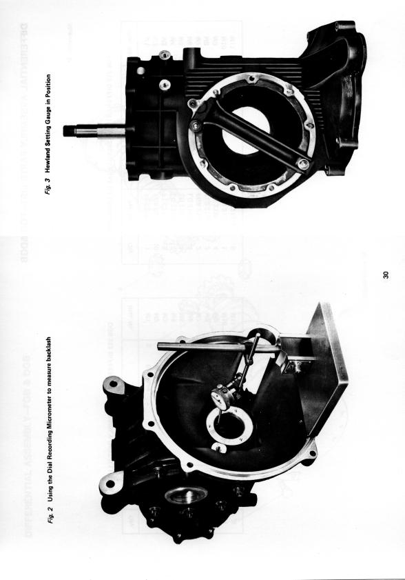
5 THE GEARBOX UNIT (continued) SETTING UP THE SELECTOR FORKS Extreme accuracy in setting up is imperative to ensure that gears engage freely, and to avoid uneven or excessive wear. The use of a Hewland Forksetting Jig is strongly recommended. Designed specifically for FT/FGT will save costly setting-up time and vastly reduce the possibility of error. (Fig. 1) Note that when two layshaft gears run together, their chamfered sides must face each other (see diagram A). Warm the bearing carrier and drop in the pinion tail bearing as described above. Place the jig in a vice. Slide the hubs with top gear and thrust washer, on to the dummy pinion. Attach the bearing carrier to the jig, using temporary nuts. Tighten the pinion nut. Then check for correct clearance on top gear. (.008 in. to.010 in.). (For FGB see page 31) Remove from jig. Fit selector forks to rods together with nuts and washers. Build up the hubs, gears and clutch rings, and slide them back on to the setting jig. Fig. 1 Hewland Forksetting Jig (c)when fully engaged with either gear there should still be in. clearance between the gear and clutch-ring faces. (d)lf clutch-ring is over engaged it could result in gears overheating and seizing up or cause excessive wear on selector fork. 8. Tighten all three selector rods using new nuts and tabs, at the same time, make sure that the selector rod heads are correctly aligned, and that there is clearance between them (but not excessive. Remove From Jig Warm up surrounding area and fit layshaft bearing. Build up the complete layshaft assembly with gears, spacers and thrust washer. Replace in bearing carrier. Put the complete assembly back into the jig. Recheck all clearances. Test all movements. When satisfied, remove the assembly from jig and bolt it into the gearbox, using a jointing compound. Tighten the nyloc nuts around the bearing carrier. Replace nuts on pinion, layshaft and tighten to the correct torque (See note). Put in split pins. Replace the selector finger housing and selector finger, renewing gasket (6). Fit new gasket (4) and replace the end cover. 7. Adjust the forks individually. Correct positioning requires that: (a)the clutch ring should be centred on its hub, between the two gears. (b)the clutch ring should engage fully with either gear. Note: The correct torque is 115 ft/lbs for pinion nut, and 80 ft/lbs for nut.
6
7 GEARBOX UNIT PARTS LIST Illus. No. Al A2 A3 A4 A5 A6 A7 A0 A9 A10 All A12 Al3 Al4 Al5 Al6 Al7 Al8 Al9 A20 A21 A22 A23 A24 A25 A26 A26 A26 A27 A28 Description Part No. Qty. Nut 5/16 in. UNF Nyloc FT Washer 5/16 in. Chamfered flat FT End Cover - Standard FT Gasket, End Cover FT Selector Finger Housing FT Gasket, Selector Finger Housing FT Nut, Layshaft (R.H.) FT Split Pin FT Bearing, Layshaft FT Stud FT Screw, Bearing Retaining FT Bearing Carrier FT Screw FT Spring FT Ball FT Plunger FT Spring, FT Plug FT Thrust Washer FT Spacer FT Layshaft (see ratio chart) FT Bearing FT First and Reverse Sliding Gear FT Hub Front (FT only) FT Hub Front (Length 3 l/l6 in.) FG Hub Front (Length 2 15/16 in.) FGA226 1 Needle Bearing FT Clutch Ring (FT only) FT Illus. No. Description Part No. Qty. A28 Clutch Ring (FG/FGA) DG A29 Hub Centre (FT only) FT A 2 9 Hub Centre (FG/FGA) FG A30 Hub Rear (FT only) FT A30 Hub Rear (FG/FGA) FG A31Inner Track 5th Gear FT A32 Thrust Washer FT A33 Stud FT A34 Nut, Pinion (L.H.) FT A35 Selector Finger FT A36 Bush FT A37 0 Ring FT A38 Spring FT A39 Ball FT A40 Screw FT A41Plunger FT A42 Screw (not illus.) FT A43 Selector Rod 1stlRev. FT A44 Selector Rod 2ndI3rd FT A45 Selector Rod 4thl5th FT A 4 6 Selector Fork lst/rev. FT A 4 7 Selector Fork 2ndl3rd FT A48 Selector Fork 4th/5th FT A50 Nut FT A51 Screw FT A52 Spacer FT A53 Plate FT A54 Screw FT A55 Spacer (various sizes) FT
8 THE MAIN CASE & DIFFERENTIAL COMPARTMENT-FT 200 Removal and replacement of units and assemblies. Refer to Illustration 5. DIFFERENTIAL AND DRIVE 5. Fit a new oil seal (32). Replace circlips if re- LAYSHAFT BEARING quired, and pay particular attention to bearings. 1. Remove the slave cylinder securing bolts and washers and take off cylinder (18) complete with 1. clutch push-rod. N.B. unhook spring attached to side plare. 2. Take off the left-hand side plate, having first removed the UNF Nyloc nuts and washers and UNF nuts (5/16 in.) on the tie bars. Loosen with light blows from a plastic mallet, and remove differential assembly. 3. Remove the right-hand side-plate. 6. When bolting the spigot to its housing, put a smear of locking fluid on the three cap screws and jointing compound on spigot face. To remove the layshaft bearing, first remove the reverse idler gear by taking out the split pin (40) from the castellated nut (14). Check the gear and bearing for wear and re-assemble in the reverse order. 7. Check that the bearing carrier rotates freely after tightening down the two swivel pins (25). 2. Remove the locating bolt (38) on under side of the main case. Warm up the main case surrounding the bearing area, until sufficiently watm to allow the end bearing to be lightly tapped out. 3. Remove all drain plugs. Wash out the main case to remove any sludge. Re-assemble in reverse order to above. 4. Warm up main case and re-assemble in reverse order. When inserting bearing (42) care should be taken to ensure that the locating hole on bearing (42) is in line with bolt (38). CLUTCH SHAFT 1. Slacken the top and bottom swivel pins (25) and slide off, the thrust bearing (36) and bearing carrier (35) from the end of the clutch shaft. 2. Remove the clutch fork split pin (39) and clevis pin (26) and detach clutch fork (24). PINION REMOVAL To remove the pinion, proceed as follows: Knock back tab washers (4) and remove bolts (3). Remove clamp plate (7). 3. Remove the cap screws (34). Tap out complete clutch shaft assembly. 4. Remove circlip (29) from clutch shaft, press out clutch shaft. Remove circlip (30) from spigot housing (33) and withdraw bearing and oil seal. Re-assemble in reverse order to above, noting the following: Warm up outside area of main case sufficiently to remove pinion bearing, Particular attention should be given to the shim or shims under pinion bearing.
9 DISMANTLING THE SUB-ASSEMBLIES DIFFERENTIAL (Illustration D) FINAL DRIVE -OUTBOARD BRAKES FINAL DRIVE - INBOARD BRAKES The following instructions apply to the cam and pawl type differential FT 200 Gearbox Bend back the tabs (18). remove the bolts (19) and take off the crown wheel (17). Remove in turn the outer housing (15), outer cam track (14) and inner cam track (12). Remove the eight plungers (pawls) (13) from the plunger carrier (11). Wash and examine for wear or damage with particular attention to pawls, and profiles of the cam tracks. Ensure that: The splines of the inner cam track are towards the drive shaft (3). New bolts and tabs are used for the crown wheel. Tighten with a torque spanner to 75 ft/lbs Smear bolts with locking fluid. Left Hand Side Plate (Illustration D) 1. Remove the drive shaft circlip (20) and knock 1. Remove the drive shaft circlip (4) and knock out out the shaft (3). shaft. 2. Support the side plate on fire bricks and warm it, having first covered the oil seal (6) with a block of metal for protection. The outer track of the differential bearing (10) and the shims (9) should now drop out. 3. Remove the large circlip (6) which retains the side plate bearing (7) and oil seal (6). so that both can be withdrawn. Right Hand Side Plate Follow the same procedure as above. Reassemble in reverse order to above, fitting new oil seals if necessary. Left Hand Side Plate (Illustration E) 2. Support the side plate on fire bricks and warm it, having first covered the oil seal (2) with a block of metal for protection. The outer track of the differential bearing (7), the shims (6), the spacer (5) and the drive shaft bearing (3) should now drop out. Right Hand Side Plate Follow same procedure as above. Re-assamble in reverse order to above, fitting new oil seals if necessary. N.B. On reassembly use a good quality grease to lubricate the inner cam track bearing surfaces. We recommend the use of Molyslip grease for this purpose. Reassemble in reverse order to above. 9
10
11 MAIN CASE PARTS LIST-FT 200 illustration B Illus. No. Description Part No. Qty. Illus. No. I Description I Part No. I Qty. Bl B2 B3 B4 B5 B6 B7 B8 B9 B10 B11 B12 B13 B14 B15 B16 B17 B17 Not illus. B18 B19 B20 B21 B22 Main Case Drain Plug Bolt, 5/16 in. UNF Tab Washer Shims Thou. Bearing Clamp Plate Dowel Reverse Idler Complete Reverse Idler Gear Bearing Spigot Washer Nut Studs Retainer Reverse Stud (outboard brakes) Stud (inboard brakes) Screw (inboard brakes) Cylinder Nut Bolt Rod Nosepiece FT FT FT FT FT 2253 FT FT FT FT FT FT FT FT FT FT FT FT FT 2012A 8 FT FT FT FT FT FT B23 B24 B25 B26 B27 B28 B29 B30 B29 B32 B33 B34 B35 B36 B37 B38 B39 B40 B41 B42 B43 B44 Spring Clutch Fork Swivel Bolt Clevis Pin Pivot Washer Circlip Circlip Bearing Oil Seal Spigot (state length A when ordering) Screws, Cap, 1/4 in. UNC Bearing Carrier (state length B when ordering) Bearing Clutch Shaft (state engine/adaptor etc. when ordering) Screw Retaining Split Pin Split Pin Washers Bearing Inspection Plug Washer FT FT FT FT FT FT FT FT FT FT FT FT FT FT 245A 1 FT FT 2342 DG 2571 FT 2377 FT 2585 FT 2291 TL 2011 FGB
12
13 MAIN CASE PARTS LIST-FG 400 & FGA illustration C Illus. No. Description Part No. Qty. Illus. No. Description Part No. Qty. Cl Main Case c 2 Drain Plug c3 Inspection Plug c4 Bearing (Inset C) c4 Bearing (Inset D) c5 Nut (Inset C) c5 Nut (Inset D) C 6 Spacer Pinion Bearing c 7 Shims C8 Dowel C9 Reverse Idler Complete Cl0 Reverse Idler Gear Cl1 Bearing Cl2 Spigot Cl3 Washer Cl4 Nut Cl5 Stud Cl6 Retainer Reverse Cl7 Stud Not Illus. Screw Not Illus. Stud (FGA only) Cl8 Cylinder Cl9 Nut C20 Bolt c 2 1Rod FG FT TL HC FGA HC A 1 FGA.2221 A 1 HC8.2222A 1 HC FT FT FT FT FT FT FT FT FT FT 2012A 11 FT FGA FG FT FT LG c 2 2 Nosepiece FT C23 Spacer Pinion Head FG C24 Clutch Fork DG C25 Swivel Bolt FT C 2 6 Clevis Pin FG C27 Pivot FG C28 Washer FT c 2 9 Circlip FT C30 Circlip FT c 3 1Bearing FT C32 Oil Seal FT c 3 3 Spigot (state length A when ordering) FG 244-S 1 c34 c 3 5 Bearing Carrier (state length B when ordering) FT C36 Bearing FT 245A 1 c37 Clutch Shaft (state engine/adaptor etc. when ordering) FG C38 Screw Retaining FT c39 Split Pin DG C40 Split Pin FT c41 Washer FT C42 Bearing FT c43 Roll Pin (reversed pinion bearing) FG 2222E 2 c44 Washer FGB
14
15 GEARBOX COMPONENTS PARTS LIST-FGB Illustration L Illus. No. Description Part No. Qty. Replaces Parts on FGA Part No. Ill/Item No. Ll L2 L3 L4 L5 L6 L7 L8 L9 L10 Lll L12 L13 L14 L15 Main Case Washer Oil Feed Plug Dowel/Oil Union Crown Wheel & Pinion 8/31 Crown Wheel & Pinion 8/35 Tab Washer Bolt Pinion Bearing Shim (various sizes) Hub, Rear Inner Track Nut, Pinion LH Bearing Carrier Clutch Shaft! FGB FGB FGB FT FGB FGB 221 B 1 FGB 221D 1 TL TL TL FGB 2232 AR FGB FGB FGA FGB FGB FG 201 Cl TL 2011 FT 2015 C8 FG 221 B F19 FG 221D F19 FGA 2221c4 HC c7 FG 228 A30 FT 229 A31 FT 2294 A32 FT 230 A34 FT 202 Al4 FG 239- c37!"note: State engine/adaptor etc. when ordering. 15
16 THE MAIN CASE & DIFFERENTIAL COMPARTMENT-FG 400,FGA & FGB Removal and Replacement of Units and Assemblies (Refer to l//us. C) DIFFERENTIAL AND DRIVE 1. Remove the slave cylinder securing bolts and washers and take off slave cylinder (18) complete with clutch push-rod. 2. Take off the left hand side plate, having first removed the nuts and washers (5/16 in. UNF) and nuts (3/8 in. UNF) on the four tie bars. Loosen with light blows from a plastic mallet, and remove differential assembly. 3. Remove the right hand side plate. Re-assemble in reverse order to above. CLUTCH SHAFT Reassemble in reverse order to above, noting the following: 5. Check spigot is tight in case. 6. Fit a new oil seal (32). Renew circlips if required, and pay particular attention to bearings. 7. Check that the bearing carrier rotates freely after tightening down the two swivel pins (25). PINION REMOVAL LAYSHAFT BEARING 1. To remove the layshaft bearing first remove the reverse idler gear by taking out the split pin (40) from the castellated nut (14), remove nut and washer. Check gear and bearing for wear. 2. Remove the locating bolt (38) on under side of the main case. Warm up the main case surrounding the bearing area, until sufficiently warm to allow bearing to be lightly tapped out. 3. Remove all drain plugs. Wash out the main case to remove any sludge. 4. Warm up main case and re-assemble in reverse order. When inserting bearing (42) care should be taken to ensure that the locating hole on bearing is in line with bolt 1. Slacken off the top and bottom swivel pins (25) To remove pinion, proceed as follows: and slide the thrust bearing (36) and carrier (35) off the end of the clutch shaft. 1. Remove bearing retaining nut (5). 2. Remove the clutch fork (24), after taking out the 2. Warm up outside area of main case sufficiently split pin and clevis pin. to remove pinion bearing. 3. Unscrew spigot from case and remove complete 3. Particular attention should be given to the shims assembly. under pinion bearing. Alternate method without removal of spigot: 3(a) Remove clutch shaft circlip (29) and knock shaft out through front of spigot. 4. Remove circlip (30) and knock bearing out of spigot, into differential compartment. Remove oil seal. 16
17 DISMANTLING THE SUB-ASSEMBLIES Refer to Illustrations F, G orh DIFFERENTIAL The following are general instructions that cover the cam and pawl type differential. Minor differences do however occur between FG 400 and FGA gearboxes. Reference to parts list may be required Bend back the tabs (20) remove the bolts (21), take off crown wheel (19). Remove in turn the outer housing (17), outer and inner cam tracks (16-14). Remove the eight plungers (pawls) (15) from the plunger carrier (13). Wash and examine for wear or damage, with particular attention to pawls, and profiles of the cam tracks. Assemble in reverse splines of the inner left hand drive shaft. order, making certain that cam track are towards the Always use new bolts and tabs for crown wheel. Tighten to 75 ft/lbs Smear bolts with locking fluid. N.B. On reassembly use a good quality grease to lubricate cam lobes and bearing faces. Molyslip is recommended. FINAL DRIVE - FG 400 SIDE PLATES FOR OUTBOARD BRAKES. (Illus. F) 1. Remove drive shaft circlip (22) and knock out shaft. 2. Support the side plate on fire bricks, and warm it, having first covered the oil seal (7) with a block of metal for protection. The outer track of the differential bearing (11) and the shims (10) should now drop out. 3. Remove the large circlip (9) which retains the side plate bearing (8) and oil seal (7) so that both can be withdrawn. Re-assemble in reverse order to above, fitting new oil seals if necessary. FINAL DRIVE - FG 400 SIDE PLATES FOR INBOARD BRAKES. (Illus. G) 1. Remove drive shaft circlip (7) and knock out shaft. 2. Remove six cap screws (1) from oil seal retainer (8) and take off retainer. 3. Support side plate on fire bricks and warm it. The outer track of the differential bearing (ll), the shims (10) and drive shaft bearing should now drop out. Re-assemble in reverse order to above, fitting new oil seals if necessary. FINAL DRIVE - FGA. (Illus. H) 1. Remove drive shaft circlip (22) and knock out shaft. 2. Support the side plate on fire bricks, and warm it, having first covered the oil seal (7) with a block of metal for protection. The outer track of the differential bearing (1 the shims (10). the spacer (9) and the drive shaft bearing should drop out. Re-assemble in reverse order to above, fitting new oil seals if necessary. 17
18
19 DIFFERENTIAL & FINAL DRIVE PARTS LIST-FT 200-OUTBOARD BRAKES Illustration D Illus. No. Description Part No. Qty. Illus. No. Description Part No. Dl Nut 7/16 in. UNF Nyloc FT D2 Bolt Drive Shaft 51/4 in. p.c.d. FT D2 Bolt Drive Shaft 4 7/16 in. p.c.d. FT 2192A 6 D3 Drive Shaft 51/4 in. p.c.d. FT D3 Drive Shaft 4 7/16 in. p.c.d. FT 219A 2 D4 Nut 5/16 in. UNF Nyloc FT D 5 Side Plate FT D6 Oil Seal FT D7 Bearing FT DB Circlip FT D9 Shims thou. FT 2061 D10 Bearing FT Dll Plunger Carrier FT D12 inner Cam Track FT D13 Plungers FT D14 Outer Cam Track FT D15 D16 D17 D17 D17 D17 D17 D18 D19 D20 D21 D22 D23 D24 D25 D26 Outer Housing Side Plate Crown Wheel & Pinion 7:31 Crown Wheel & Pinion 9:31 Crown Wheel & Pinion 8:31 Crown Wheel & Pinion 10:31 Crown Wheel & Pinion 13:36 Tab Washer Bolt Circlip Limited Slip Differential Drive Shaft H.S Bolt Nut 3/8 in. UNF Nyloc Washer Tie Bar FT FT FT FT 221A 1 FT 221B 1 FT 221C 1 FT 221M 1 FT FT FT FT FT FT FT FT FT
20
21 DIFFERENTIAL & FINAL DRIVE PARTS LIST-FT 200-INBOARD BRAKES Illustration E Illus. No. Description Part No. Qty. Illus. No. Description Part No. Qty. El E2 E3 E4 E5 E5 E6 E7 E8 E9 El0 E11 El2 El3 Side Plate Oil Seal Bearing Circlip Spacer L/H Spacer R/H (not illus.) Shim thou. Bearing Plunger Carrier Inner Cam Track Plungers Outer Cam Track Outer Housing Crown Wheel & Pinion 7:31 FT 205B 1 FT FT 2053A 2 FT2191A 2 FT 2052A 1 FT 2062A 1 FT 2061 FT FT FT FT FT FT FT El3 El3 El3 El3 El4 El5 El5 El5 El6 El7 El8 El9 E20 E21 E22 Crown Wheel & Pinion 9:31 Crown Wheel & Pinion 8:31 Crown Wheel & Pinion 10:31 Crown Wheel & Pinion 13:36 Side Plate Drive Shaft H.S Drive Shaft H.S. C.V. Joint Drive Shaft V.W. C.V. Joint Tab Washer Bolt Tie Bar Nut 5/16 in. UNF Nyloc Washer Screw Limited Slip Differential FT 221A 1 FT FT 221C 1 FT 221M 1 FT 206B 1 FT 218A 2 FT FT 218F 2 FT FT FT 262A 3 FT FT FT FT
22
23 DIFFERENTIAL & FINAL DRIVE PARTS LIST-FG 400-OUTBOARD BRAKES Illustration F Illus. No. Description Part No. Qty. lllus. No. Description Part No. Qty. Fl F2 F3 F4 F5 F6 F7 F6 F9 F10 Fll F12 F13 F14 F15 F16 Nut 7/16 in. UNF Nyloc Bolt Drive Shaft 5% in. p.c.d. Nut 5/16 in. UNF Nyloc Washer Side Plate Oil Seal Bearing Circlip Shim thou. Bearing Limited Slip Differential Plunger Carrier Inner Cam Track Plunger Outer Cam Track FT 2195 FT 2192 DG 219 FT 2013 FT 2027 FG 205 LG 2054 LG 2053 LG 2052 DG 2061 DG 2051 DG 212 DG 214 LG 216 LG 217 LG 215 6/ F17 Outer Housing DG F18 Side Plate FG F19 Crown Wheel & Pinion 7:31 FG F19 Crown Wheel & Pinion 9:31 FG 221A 1 F19 Crown Wheel & Pinion 8:31 FG 221 B 1 F19 Crown Wheel & Pinion 10:31 FG 221C 1 F20 Tab Washer FT F21Bolt FT F22 Circlip LG F23 Bolt LG F24 Drive Shaft HS 1400 DG F25 Nut 3/B in. UNF Nyloc FT F26 Tie Bar L G F27 Tie Bar DG F28 Washer FT F29 Dowel DG 213A 5 23
24
25 DIFFERENTIAL & FINAL DRIVE PARTS LIST-FG 400-INBOARD BRAKES Illustration G Illus. No. Description Part No. Qty. Illus. No. Description Part No. Qty. Gl Screw, Cap, 1/4 in. UNC G2 Oil Seal G3 Bearing G4 Nut 5/16 in. UNF Nyloc G5 Washer G6 Side Plate G7 Circlip G8 Retaining Plate G9 Washer G10 Shim thou. G11 Bearing G12 Limited Slip Differential G13 Plunger Carrier G14 Inner Cam Track G 15 Plunger G 16 Outer Cam Track FG LG DG 2053A 2 FT FT FG DG 2191A 2 DG 206Al 2 FT DG 2061 DG DG DG LG LG LG G17 G18 G19 G19 G19 G19 G20 G21 G22 G23 G24 G24 G24 G25 G26 G27 Outer Housing Side Plate Crown Wheel & Pinion 7:31 Crown Wheel & Pinion 9:31 Crown Wheel & Pinion 8:31 Crown Wheel & Pinion 10:31 Tab Washer Bolt Dowel Drive Shaft H.S Drive Shaft 100 ST Drive Shaft 89 ST Drive Shaft V.W. C.V. Nut 3/8 in. UNF Nyloc Tie Bar Tie Bar DG FG FG FG 221A 1 FG 221 B 1 FG 221 C 1 FT FT DG 213A 5 DG 218A 2 DG DG 218D 2 FG 218A 2 FT LG DG 262A 2 25
26
27 DIFFERENTIAL & FINAL DRIVE PARTS LIST-FGA Illustration H Illus. No. Description Part No. Qty. Illus. No. Description Part No. Qty. Hl Drive Shaft 12 holes Hl Drive Shaft 100 ST Hl Drive Shaft H.S H2 Washer H3 Stud H4 Nut 5/16 in. UNF Nyloc H5 Washer H6 Side Plate H 7 Oil Seal H 8 Bearing H9 Spacer L/H H9 Spacer R/H (not illus.) H10 Shim thou. Hll Bearing H 12 Limited Slip Differential FGA 218A 2 FGA FGA 218C 2 FT FGA FT FT FGA 205C 1 FT TL FGA 2052A 1 FGA 2062A 1 FT 2061 FT TL H13 H14 H15 H16 H17 H18 H19 H19 H19 H19 H20 H21 H22 H23 H24 H25 Plunger Carrier Inner Cam Track Plungers (thickness 5/16 in.) Outer Cam Track Outer Housing Side Plate Crown Wheel & Pinion 7:31 Crown Wheel & Pinion 9:31 Crown Wheel & Pinion 8:31 Crown Wheel & Pinion 10:31 Tab Washer Bolt Circlip Tie Bar Tie Bar Nut 3/8 in. UNF Nyloc TL TL TL TL TL FGA 206A 1 FG FG 221A 1 FG 221 B 1 FG 221C 1 FT FT FT 2191A 2 LG DG 262A 2 FT
28
29 DIFFERENTIAL ASSEMBLY PARTS LIST-FGB &DGB Illustra tion M FGB 212 DIFFERENTIAL ASSEMBLY (AS ILLUSTRATED) DGB 212 DIFFERENTIAL ASSEMBLY (NOT ILLUSTRATED) Illus. No. Description Part No. Qty. Illus. No. Description Part No. Qty. Ml End Plate M2 Bolt M3 Tab Washer M4 Clutch Plate, Belville M 5 Disc M 6 Clutch Plate M 7 Ring, Side Gear M 8 Side Gear M8 Pinion Gear Ml0 Differential Case Ml1 Screw FGB FGB FT LG LG LG FGB TL LG FGB213 1 FGB Ml M2 M3 M4 M5 M6 M7 M8 M9 Ml0 Ml1 End Plate Bolt Tab Washer Clutch Plate, Belville Disc Clutch Plate Ring, Side Gear Side Gear Pinion Gear Differential Case Screw DGB FGB FT LG LG LG FGB LG LG DGB FGB
30
31 SETTING-UP THE CROWN WHEEL & PINION Crown wheel and pinion sets are supplied as matched and lapped pairs, tested and passed before leaving the factory, and therefore should only be fitted to run as a pair, marked with a HE number on each part. Setting up is possible with the use of engineers blue, but the faster and more positive method is to use a Hewland pinion depth gauge. Procedure is as follows: SETTING PINION ON FT 200 Refer to illustration B When fitting a new pinion it is also advisable to fit a new pinion bearing (6). Press bearing (6) onto pinion shaft, ensuring flanged shoulder is correct way round. Select a shim (5), i.e. used undamaged shims from removed pinion. Warm up the outside of main case. Insert shim in correct position and drop pinion and bearing into the main case. Fit clamp plate (7), insert four bolts (3). tighten into clamp plate. Allow main case to cool. USING THE HEWLAND SETTING GAUGE TO CHECK PINION DEPTH 7. Place setting gauge in position in place of side plate of main case, Bolt across face. 8. Using a feeler gauge, determine the clearance between the setting gauge and the pinion. The correct clearance is marked on the pinion and should be achieved using shims (5). 9. When pinion clearance is correct, remove clamp bolts (3), put on clamp plate tab washers (4) smear Locktite on threads, re-fit bolts (3) and tighten into clamp plate (7). Knock ever tab washers. SETTING PINION OF FG400 & FGA Refer to Illustration C. 1. When fitting a new pinion it is also advisable to fit a new pinion bearing. All FGA gearboxes are fitted with a larger pinion bearing (4-FGA 2221). and to some FG 400 gearboxes up to The pinion bearing is fitted reversed in some FG gearbox main cases prior to 1976, and in all FG gearboxes subsequently. When separating the pinion from the main case, make special note of order and location of pinion bearing, shims, and any spacers that might be present, to ensure correct re-assembly Press bearing (4) onto pinion shaft, ensuring flanged shoulder is correct way round. Select a shim (7), i.e. used shims from removed pinion. Warm up the outside of main case. Insert shim (7) in correct position and fit pinion and bearing into the main case. Using old nut (5), and spacer (6), if fitted lock bearing into main case. Allow main case to cool. USING THE HEWLAND SETTING GAUGE TO CHECK PINION DEPTH 7. Put setting gauge in position in place of side plate of main case, bolt across face. 8. Using a feeler gauge, determine the clearance between the setting gauge and the pinion. The correct clearance is marked on the pinion, and should be achieved using shims (7). 9. When pinion clearance is correct, remove old nut (5) and fit new nut. Use a little Locktite and tighten to a torque of 200 ft/lbs 10. Using round-nosed punch, knock the grooved part of nut into the cut in thread of bearing. SETTING PINION OF FGB Refer to Illustration L When fitting a new pinion it is also advisable to fit a new pinion bearing. Press bearing (9) onto pinion shaft, making sure flanged shoulder is correct way round. Select a shim (10). i.e. used undamaged shims from removed pinion. Warm up outside of main case. Insert shim (10) in correct position and fit pinion and bearing into main case. Insert 6 bolts (8) (with plain washers to protect magnesium face), and tighten. Allow main case to cool. 31
32 Turn the pinion shaft by hand to test the pre- load. Adjust by means of shims until satisfactory. Use the Hewland setting gauge to check pinion depth, as for FG400 or FGA. Adjust shimming as required until correct clearance is obtained. Finally re-assemble 6 bolts (8) with new tab washers and tighten. Tab over washers. N.B. Turn the pinion with hubs removed. Using reasonable effort, it should be possible to turn it by gripping the splines by hand, but more effort will be needed with dummy bearings than with real ones. Make sure there is some evidence of backlash. Absence of backlash will give a false impression of pre-load. Re-assemble as follows: Press inner bearings onto differential assembly. Warm up one side plate (FT outboard, FG 400) and fit oil seal, drive shaft bearing and circlip or plate. Press the drive shaft into the bearing and retain with circlip. 11. Check the position of Hubs as this may vary with new setting of pinion, as described on page 36 and adjust if required. 7. Insert shim or shims, and bearing outer track. Place heavy weight on bearing track to flatten shimming. Allow to cool. ADJUSTING PRE-LOAD OF DIFFERENTIAL FT200, FG400, FGA, FGB Although differences exist between the method of retaining the drive shaft bearing in the side plate, the method of setting the crown wheel up is the same in all cases. Assemble the drive shaft bearings in the side plates, where they take the differential thrust (FT inboard, FGA), together with spacers. With other gearboxes, this can be accomplished at a later stage. Assemble differential unit, and fit crown wheel. Use solid dummy bearings in place of the two differential taper bearings. The thickness of shims is critical. If they have to be replaced, make sure it is with shims of the same thickness. Fit the differential unit and side plates to the main case. Bolt up, including tie bars, to normal tension. TO ADJUST THE BACKLASH For this operation you will require a post-mounted dial indicator with an extended probe. (Fig.2 page 30) 1. Remove the solid dummy bearings from the differential unit and replace them with dummy bearings. (Real bearing with increased tolerances for easy substitution). 2. Insert the probe of the dial indicator through spigot housing until it touches one of the teeth of the crown wheel. Note the reading on the dial indicator. Turn pinion by hand to rotate crown wheel, and take at least 12 readings. (14 readings are standard practice in our workshops.) Minimum reading should be.004 in. 3. To increase or decrease backlash, change shims from one side of differential to the other, but remember that once the pre-load has been set, you can use only the shims that are already there. 8. Repeat for other side plate. After cooling, assemble one side to the main case. Complete the assembly of the differential and drive unit as described above. N.B. If renewing the differential bearings, make certain that the width of the new bearings, also when using dummy bearings, are the same as old bearings being replaced. Any differences must be adjusted in final shimming. 32
33 ALTERNATIVE DIFFERENTIAL-FGA 1 \ Illus. No. I Description I Part No. Qty. J2 J3 J4 J5 J6 Limited Slip Differential Plunger Carrier Inner Cam Track Plungers (thickness 3/8 in.) Outer Cam Track Outer Housing TL2.212 TL2.214 TL2.216 LG 217 TL2.215 TL2.213 Fitted as standard from gearbox number FGA
34 OIL PUMP Illustration K The oil pump is located on the end cover of the gearbox unit. It is extremely strong and unlikely to suffer serious wear. Illus. No. Description Part No. Qty. To Remove: 1. Slacken and remove the 5/16 in. UNF nyloc end cover securing nuts (8 off) Gently tap the end cover off gearbox housing. Remove circlip (8) and pull off gear (7) removing the key on the shaft. 4. Remove the cap screws (1) and take off top cover (3). 5. Remove both gears from housing. K Kl K2 K3 K4 K5 K6 K7 K8 K9 K18 Pump Screws, 2BA Pump Body (Combined End Coverl Pump Cover Gear Gear Key Gear, Internal Circlip Gear Plug (use only when Alternator not required) FT 265 DG FT 2652 FT 2653 DG 2654 DG 2655 DG 2656 FT 2657 DG 2658 FT 2659 FT Clean and check gears and body for possible scouring. 7. Re-assemble in reverse order. 34
35 OIL PUMP-FT & FG illustration N Illus No. Description Part No. Qty. Illus. No. Description Part No. Qty. Nl Body, Oil Pump N 2 Selector Finger N3 Pump Cover, End N4 Key N5 Rotor, Driver N6 Rotor, Idler N 7 Body, Pump NB Pump Cover, Front N9 Screw, 4BA N10 Gear, Rotor Driver N11 Circlip N12 Screw, 2BA N13 Nut, Nyloc 5/16 in. N14 Washer, 5/l6 in. N 15 Stud, Short FT 203P 1 FGA FGA6.2652A 1 DG DG DG FGA FGA FGA FGA DG DG FT FT FGA N16 N17 N18 N19 N20 N21 N22 N23 N24 N25 N26 N27 N28 N29 N30 Screw 2BA Washer Washer, Fixed Gear, Idler, Oil Pump Bearing, Idler Gear Shaft, Idler Gear Stud, long Nut, Nyloc, 3/B in. Gear, Drive, Oil Pump Circlip, Bearing Retaining Bearing, Drive Shaft Ball Locating Drive Shaft, Pump Drive Insert Layshaft Dowel FGA FGA A 1 FGA6.2659C 1 FGA6.2659A 1 FGA62659D 1 FT 2651 OB 1 FGA FT FT 2659A 1 HC FT 2659D 1 FT 2659E 1 FT 2659C 1 FT FGA6.2029A 2 35
36 SETTING GEAR POSITIONS FOR GEARBOXES WITH ROTATING TOP GEAR THRUST WASHER SETTING GEAR POSITIONS IN MAIN CASE (Fig. 4) 1. With pinion set-up in main case, slide front hub onto pinion shaft. 2. Slide spacer next to froht hub. 3. With the aid of a machined straight-edge check the level of the spacer relative to main case rear face. If lower - Use longer front hub or shim at position X-X. If higner (proud) - Use shorter -front hub or grind face of hub at position X-X. If level (flush) - Setting is correct. OR SETTING JIG STUDS SETTING GEAR POSITIONS WITH SELECTOR FORK JIG 1. Using methods described above, achieve spacer level with front face of bearing carrier. 2. Set selector forks..920" SPACER FOR FGB 5 SPEED Notes: All bearing carriers set by this method are interchangeable on main cases. Clearance between fop gear thrust bearing and casting is not to a critical tolerance (min in). 36
SERVICING INSTRUCTIONS AND ILLUSTRATED PARTS LIST FOR HEWLAND DG-300 MARK 2 GEARBOX
 SERVICING INSTRUCTIONS AND ILLUSTRATED PARTS LIST FOR HEWLAND DG-300 MARK 2 GEARBOX HEWLAND ENGINEERING LTD, WALTHAM ROAD, WHITE WALTHAM, MAIDENHEAD, BERKSHIRE, SL6 3LR ENGLAND TELEPHONE + 44 (0)1628 827600
TRANSAXLE GEARBOX UNITS
 THE SERIES TRANSAXLE GEARBOX UNITS These units are designed for use with 300 to 450 cu. inch competition engines, and are manufactured as two, four and five speed models. The present manual deals with
TRANSAXLE GEARBOX UNITS
 THE SERIES TRANSAXLE GEARBOX UNITS These units are designed for use with 300 to 450 cu. inch competition engines, and are manufactured as two, four and five speed models. The present manual deals with
THE DG 300 MARK 2 5-SPEED TRANSAXLE GEARBOX UNIT
 THE DG 300 MARK 2 5-SPEED TRANSAXLE GEARBOX UNT The Mark 2 DG300 Gearbox has five forward ratios and reverse. t is designed for use with rear engine competition cars having a capacity of up to 4% litres.
215 Service Manual SERVICE MANUAL. 215 Series Axle
 SERVICE MANUAL 215 Series Axle Issue 1 - January 2002 CONTENT: 1 INTRODUCTION... Page - 1-2 GENERAL DESCRIPTION... Page - 1-3 IDENTIFICATION... Page - 1-4 GENERAL SERVICE INFORMATION... 4.1 Routine Maintenance...
615 Service Manual SERVICE MANUAL. 615 Series Axle
 SERVICE MANUAL 615 Series Axle Issue 1 - February 2002 CONTENT: 1 INTRODUCTION... Page - 1-2 GENERAL DESCRIPTION... Page - 1-3 IDENTIFICATION... Page - 1-4 GENERAL SERVICE INFORMATION... 4.1 Routine Maintenance...
SECTION H STEERING. Section Description Page No. H.1 GENERAL DESCRIPTION 3 H.2 STEERING WHEEL 3 H.3 INNER COLUMN 5 H.
 SECTION H STEERING Section Description Page No. H.1 GENERAL DESCRIPTION 3 H.2 STEERING WHEEL 3 H.3 INNER COLUMN 5 H.4 OUTER COLUMN 5 H.5 STEERING UNIT LOCK STOPS 6 H.6 STEERING UNIT 6 H.7 STEERING ARMS
HOLINGER RD6-S GEARBOX MANUAL
 HOLINGER RD6-S GEARBOX MANUAL Rev A. Date: 03/11 Holinger Engineering Gearbox Manual Page 1 FOREWORD The Holinger RD6-S is a sequential-shift dog-change gearbox primarily designed for use in front-engine,
SERVICE MANUAL. 915 Series Axle
 SERVICE MANUAL 915 Series Axle Issue 1 September 2003 CONTENT: 1 INTRODUCTION Page 3-2 GENERAL DESCRIPTION Page 3-3 IDENTIFICATION Page 3-4 GENERAL SERVICE INFORMATION Page 5 -.1 4.1 Routine Maintenance
DRIVE AXLE Volvo 960 DESCRIPTION & OPERATION AXLE IDENTIFICATION DRIVE AXLES Volvo Differentials & Axle Shafts
 DRIVE AXLE 1994 Volvo 960 1994 DRIVE AXLES Volvo Differentials & Axle Shafts 960 DESCRIPTION & OPERATION All 960 station wagon models use type 1041 rear axle assembly. All 960 4-door models use type 1045
HOLINGER SF GEARBOX MANUAL
 HOLINGER SF GEARBOX MANUAL Approved By: Leigh Nash Date: 26/05/2011 Rev: D Date: 11/11 Holinger Engineering Gearbox Manual Page 1 FOREWORD The Holinger SF is a sequential-shift transaxle designed for use
HKS 700E. Service Manual June Ver. 2.04
 HKS 700E Service Manual 009 June Ver..04 HKS CO.,LTD 78 KITAYAMA FUJINOMIYA SHIZUOKA JAPAN 48-09 TEL +8(0)544-54-78 FAX +8(0)544-54-40 hks_aviation@hks-power.co.jp http://www.hks-power.co.jp/hks_aviation/
Technical Information Review
 Technical Information Review While every attempt is made to ensure that the technical information we supply is as accurate and up to date as possible, from time to time, errors do occur. There may also
DRIVE AXLE Nissan 240SX DESCRIPTION & OPERATION AXLE RATIO & IDENTIFICATION AXLE SHAFT & BEARING R & I DRIVE SHAFT R & I
 DRIVE AXLE 1990 Nissan 240SX 1990 DRIVE AXLES Rear Axle - R200 240SX, 300ZX DESCRIPTION & OPERATION The axle assembly is a hypoid type gear with integral carrier housing. The pinion bearing preload adjustment
Transmission Overhaul Procedures-Bench Service
 How to Assemble the Lower Reverse Idler Gear Assembly Special Instructions In 1996 Eaton changed the reverse idler system design. In the nut design, the reverse idler bearing was lubricated through a hole
Amarillo PUMP DRIVES (250 HP THROUGH 350 HP) INSTRUCTIONS FOR REPAIRING MODELS 250, 300, and 350
 INSTRUCTIONS FOR REPAIRING MODELS 250, 300, and 350") Amarillo PUMP DRIVES (250 HP THROUGH 350 HP) INSTRUCTIONS FOR REPAIRING MODELS 250, 300, and 350 Amarillo Right Angle Pump Drives, if properly installed and maintained, should provide years of service
Amarillo PUMP DRIVES (250 HP THROUGH 350 HP) INSTRUCTIONS FOR REPAIRING MODELS 250, 300, and 350 Amarillo Right Angle Pump Drives, if properly installed and maintained, should provide years of service
1999 F-150/250 Workshop Manual
 Page 1 of 30 SECTION 205-03: Front Drive Axle/Differential Ford 8.8-Inch Ring Gear 1999 F-150/250 Workshop Manual DISASSEMBLY AND ASSEMBLY Procedure revision date: 01/08/2003 Axle Front Drive Special Tool(s)
SERVICING INSTRUCTIONS AND ILLUSTRATED PARTS LIST FOR HEWLAND MLG GEARBOXES
 SERVICING INSTRUCTIONS AND ILLUSTRATED PARTS LIST FOR HEWLAND MLG GEARBOXES HEWLAND ENGINEERING LTD, WALTHAM ROAD, WHITE WALTHAM, MAIDENHEAD, BERKSHIRE, SL6 3LR, ENGLAND LAST REVISION:- 23rd December 2013
DISASSEMBLY AND ASSEMBLY
 205-03-1 Front Drive Axle/Differential Ford 8.8-Inch Ring Gear 205-03-1 DISASSEMBLY AND ASSEMBLY Axle Front Drive Special Tool(s) 2-Jaw Puller 205-D072 (D97L-4221-A) Special Tool(s) Carrier Bearing Replacer
SERVICE SHEET No. 515
 SERVICE SHEET No. 515 MODEL D7 DISMANTLING AND REASSEMBLY OF HUBS AND BRAKES Both wheels are fitted with ball journal bearings which do not require adjustment. The bearings are packed with grease during
Service Tools. Service and Repair Manual Model 900/950/990 ITEM PART NO. DESCRIPTION ITEM PART NO. DESCRIPTION ITEM PART NO.
 12 1 3 2 4 5 8 10 6 7 9 11 14 24 12 13 17 22 29 18 23 25 19 26 15 20 27 21 16 22 33 37 38 32 31 36 30 34 35 40 41 42 43 ITEM PART NO. DESCRIPTION 1 9170 0231 30 LONG ALLEN KEY 2 9170 0737 20 3/32 PIN PUNCH
LT230T TRANSFER GEARBOX. Overhaul Manual LT230T. Verdeelbak revisieboek LT230T. Boîte de transfert Manuel de révision LT230T
 LT230T TRANSFER GEARBOX Overhaul Manual LT230T Verdeelbak revisieboek LT230T Boîte de transfert Manuel de révision LT230T Verteilergetriebe Überholungsanleitung LT230T Riduttore Manuale di revisione LT230T
Repair Manual VW 02J gearbox. INA GearBOX
 Repair Manual VW 02J gearbox INA GearBOX Special tools Pipe section, 50 mm: Press fitting of synchronizer body for third/fourth gear. Assembly of support bearing for input and output shaft. Part number:
REAR TRANSMISSION-REAR AXLE
 REAR TRANSMISSION-REAR AXLE The rear axle is of the semi-floating type with a spiral bevel drive pinion and crown wheel as shown in the section view, Fig. 168. 7 The drive is splined into the front transmission
AMARILLO PUMP DRIVES MODEL 1 OOOA, 1200, 1500, 1800
 AMARILLO PUMP DRIVES MODEL 1 OOOA, 1200, 1500, 1800 INSTRUCTIONS FOR REPAIRING MARCH 1, 1993 AMARILLO GEAR COMPANY Post Office Box 1789, Amarillo, Texas 79105 806 / 622-1273 FAX 806 / 622-3258 INSTRUCTIONS
KAM Ring and Pinion fitting instructions (Mechanical knowledge necessary, these instructions are intended as a guide)
") KAM Ring and Pinion fitting instructions (Mechanical knowledge necessary, these instructions are intended as a guide) DISMANTLE It is essential that differential components are marked in their original
KAM Ring and Pinion fitting instructions (Mechanical knowledge necessary, these instructions are intended as a guide) DISMANTLE It is essential that differential components are marked in their original
DIFFERENTIALS & AXLE SHAFTS
 DIFFERENTIALS & AXLE SHAFTS 2001 Chevrolet Camaro 2000-01 DRIVE AXLES General Motors Differentials & Axle Shafts Chevrolet; Camaro Pontiac; Firebird DESCRIPTION & OPERATION Drive axle is a semi-floating,
DRIVE AXLE - INTEGRAL HOUSING
 DRIVE AXLE - INTEGRAL HOUSING 1993 Toyota Celica 1993 DRIVE AXLES Toyota Differentials & Axle Shafts - Integral Housing Toyota; Celica All-Trac DESCRIPTION Drive axle assembly is a hypoid type with integral
REAR AXLE AND SUSPENSION RA 1
 REAR AXLE AND SUSPENSION RA1 RA2 REAR AXLE AND SUSPENSION Troubleshooting TROUBLESHOOTING Problem Possible cause Remedy Page Wanders/pulls Tires worn or improperly inflated Replace tires or inflate to
REAR DRIVE SHAFT (3S GTE ENGINE)
") SA52 REAR DRIVE SHAFT (3SGTE ENGINE) COMPONENTS SA53 NOTICE: The axle bearing could be damaged if it is subjected to the vehicle weight, such as when moving the vehicle with the drive shaft removed. Therefore,
SA52 REAR DRIVE SHAFT (3SGTE ENGINE) COMPONENTS SA53 NOTICE: The axle bearing could be damaged if it is subjected to the vehicle weight, such as when moving the vehicle with the drive shaft removed. Therefore,
'99-03 CHEVROLET/GMC IFS 4WD 6" SUSPENSION SYSTEM P/N INSTALLATION INSTRUCTIONS
 1/16/04 '99-03 CHEVROLET/GMC IFS 4WD 6" SUSPENSION SYSTEM P/N. 10-41099 INSTALLATION INSTRUCTIONS NOTE: Each Lift Kit and options to Lift Kits are packaged separately. Therefore, installation procedures
SECTION 3A FRONT DRIVE AXLE TABLE OF CONTENTS SPECIFICATIONS GENERAL SPECIFICATIONS. Description Drive Shaft Type. CV Joint Axle Housing Type
 SECTION 3A FRONT DRIVE AXLE TABLE OF CONTENTS Specifications........................ 3A-1 General Specifications.................. 3A-1 Fastener Tightening Specifications......... 3A-2 Component Locator...................
MAINTENANCE MANUAL DP-265
 MAINTENANCE MANUAL DP-265 Drive Gears Sisu Axles, Inc. Autotehtaantie 1 P.O. Box 189 FIN-13101 Hämeenlinna Finland Phone int + 358 204 55 2999 Fax int + 358 204 55 2900 DP265DG.PDF (2/2003) k Table of
AUTOMATIC TRANSMISSIONS Mitsubishi F3A20 Series TRANSMISSION APPLICATION TABLE
 Article Text ARTICLE BEGINNING AUTOMATIC TRANSMISSIONS Mitsubishi F3A20 Series APPLICATION TRANSMISSION APPLICATION TABLE Vehicle Application Transmission Model Colt 3-Speed (1990-94)... F3A21 Colt Vista
DF 78. HINT: Face the rough side of the thrust washer marked by # to the differential case. INSPECTION
 78 DIFFERENTIAL REAR DIFFERENTIAL CARRIER ASSEMBLY (w/ Differential Lock) Face the rough side of the thrust washer marked by # to the differential case. INSPECTION 1. DIFFERENTIAL SIDE GEAR (w/ LSD Differential)
DISASSEMBLY AND ASSEMBLY (Continued)
") 205-03-23 Front Drive Axle/Differential Ford 8.8-Inch Ring Gear 205-03-23 49. Measure the ring gear backlash at four places to obtain a consistent reading. 1 Mount the special tools on the indicator base.
205-03-23 Front Drive Axle/Differential Ford 8.8-Inch Ring Gear 205-03-23 49. Measure the ring gear backlash at four places to obtain a consistent reading. 1 Mount the special tools on the indicator base.
Installation and Maintenance Instructions JSE1-0128MAEAD Extruder Clutch. World Leader in Modular Torque Limiters
 World Leader in Modular Torque Limiters Installation and Maintenance Instructions JSE1-0128MAEAD Extruder Clutch 1304 Twin Oaks Street Wichita Falls, Texas 76302 (940) 723-7800 Fax: (940) 723-7888 E-mail:
Housing (Front) - Remove
 - Remove") SENR9978-01 63 1. Lift the assembly (3) of the idler gear and the hub over the housing for the crankshaft front seal (2) and insert the hub into the recess in the cylinder block. Refer to illustration
SENR9978-01 63 1. Lift the assembly (3) of the idler gear and the hub over the housing for the crankshaft front seal (2) and insert the hub into the recess in the cylinder block. Refer to illustration
FRONT AXLE 26-1 CONTENTS GENERAL INFORMATION... 2 HUB AND KNUCKLE ASSEMBLY SERVICE SPECIFICATIONS... 4 DRIVE SHAFT LUBRICANTS...
 26-1 FRONT AXLE CONTENTS GENERAL INFORMATION.................. 2 SERVICE SPECIFICATIONS................. 4 LUBRICANTS.............................. 4 SEALANTS AND ADHESIVES.............. 5 SPECIAL TOOLS...........................
Betico SB1 Compressor. Unloader Kit Installation Manual
 Betico SB1 Compressor Unloader Kit Installation Manual Contents 1. Sample of BOM for Unloader Kit Page 3 2. Regulation kit plumbing diagram Page 4 3. Disassemble standard inlet valves from machine Page
Installation and Maintenance Instructions JSE MAEAD Extruder Clutch. World Leader in Modular Torque Limiters
 World Leader in Modular Torque Limiters Installation and Maintenance Instructions JSE.5-0104MAEAD Extruder Clutch 1304 Twin Oaks Street Wichita Falls, Texas 76302 (940) 723-7800 Fax: (940) 723-7888 E-mail:
DF 15. DIFFERENTIAL 1GR-FE FRONT DIFFERENTIAL CARRIER ASSEMBLY (for 4WD) REMOVAL
 REMOVAL") DIFFERENTIAL 1GR-FE FRONT DIFFERENTIAL CARRIER ASSEMBLY (for 4WD) 15 REMOVAL 1. REMOVE FRONT WHEELS 2. REMOVE REAR ENGINE UNDER COVER ASSEMBLY (a) Remove the 6 bolts and engine under cover assembly. 3.
DIFFERENTIAL 1GR-FE FRONT DIFFERENTIAL CARRIER ASSEMBLY (for 4WD) 15 REMOVAL 1. REMOVE FRONT WHEELS 2. REMOVE REAR ENGINE UNDER COVER ASSEMBLY (a) Remove the 6 bolts and engine under cover assembly. 3.
MANUAL TRANSAXLE SECTIONMT CONTENTS IDX. Shift Control Components...34
 MANUAL TRANSAXLE SECTIONMT GI MA EM LC EC CONTENTS FE PREPARATION...3 Special Service Tools...3 Commercial Service Tools...5 NOISE, VIBRATION AND HARSHNESS (NVH) TROUBLESHOOTING...6 NVH Troubleshooting
SERVICING INSTRUCTIONS AND ILLUSTRATED PARTS LIST FOR THE HEWLAND LWS GEARBOX
 SERVICING INSTRUCTIONS AND ILLUSTRATED PARTS LIST FOR THE HEWLAND LWS GEARBOX HEWLAND ENGINEERING LTD, WALTHAM ROAD, WHITE WALTHAM, MAIDENHEAD, BERKSHIRE, SL6 3LR, ENGLAND Engineering Limited 009-00 PAGE
MANUAL TRANSAXLE Return to Main Table of Contents
 MANUAL TRANSAXLE Return to Main Table of Contents GENERAL... 2 MANUAL TRANSAXLE CONTROL... 12 SHIFT LEVER ASSEMBLY... 14 MANUAL TRANSAXLE... 15 MANUAL TRANSAXLE ASSEMBLY... 17 FIFTH SPEED SYNCHRONIZER
PROPELLER SHAFT & DIFFERENTIAL CARRIER SECTIONPD CONTENTS
 PROPELLER SHAFT & DIFFERENTIAL CARRIER SECTIONPD CONTENTS PREPARATION...2 PROPELLER SHAFT...5 On-Vehicle Service...6 Removal and Installation...7 Inspection...7 Disassembly...7 Assembly...8 ON-VEHICLE
FRONT AXLE Click on the applicable bookmark to selected the required model year
 FRONT AXLE 26-1 FRONT AXLE CONTENTS GENERAL INFORMATION.................. 2 SERVICE SPECIFICATIONS................. 4 LUBRICANTS.............................. 4 SEALANTS AND ADHESIVES.............. 5 SPECIAL
SECTION D REAR SUSPENSION. Section Description Page D.1. REMOVING AND REFITTING A REAR SUSPENSION UNIT 5
 SECTION D REAR SUSPENSION Section Description Page D.1. REMOVING AND REFITTING A REAR SUSPENSION UNIT 5 D.2. REMOVING AND REFITTING THE COMPONENTS OF THE REAR SUSPENSION 8 D.3. CHECKING AND OVERHAULING
1984 Dodge W250 PICKUP
 1984 Dodge W250 PICKUP Submodel: Engine Type: V8 Liters: 5.2 Fuel Delivery: CARB Fuel: GAS Dana 44 MODELS THROUGH 1984 2. Raise and safely support the vehicle, then remove the wheel hub and bearings as
INTRODUCTION. Ensure all works tools are in good condition and only use the correct tool for the job in hand.
 NEWAGE 9TRA GEARBOX WORKSHOP MANUAL WINGET LIMITED PO BOX 4 EDGEFOLD INDUSTRIAL ESTATE PLODDER LANE BOLTON LANCS BL4 OLS TEL ++ 44 (0) 04 854650 FAX ++ 44 (0) 04 85466 E mail service@winget.co.uk parts@winget.co.uk
Installation and Maintenance Instructions JSE2-0241MAEAD Extruder Clutch. World Leader in Modular Torque Limiters
 World Leader in Modular Torque Limiters Installation and Maintenance Instructions JSE2-0241MAEAD Extruder Clutch 1304 Twin Oaks Street Wichita Falls, Texas 76302 (940) 723-7800 Fax: (940) 723-7888 E-mail:
Rekluse Motor Sports. The z-start Clutch GAS GAS. 200, 250, and strokes. 400 and strokes
 Rekluse Motor Sports The z-start Clutch GAS GAS 200, 250, and 300 2-strokes 400 and 450 4-strokes Installation Guide Copyright 2002-2004 Rekluse Motor Sports z-start Revision 3.000 RMS100 Gas Gas z-start
A 1 SERVICE SPECIFICATIONS
 A1 A2 Clutch CLUTCH Specifications Pedal height (from asphalt sheet) Release point (from pedal stroke end position) Push rod play at pedal top Pedal freeplay Disc rivet head depth Disc runout Diaphragm
TC20 Chain Driven Power Take-Off Overhaul Instructions
 TC20 Chain Driven Power Take-Off Overhaul Instructions Table of Contents Section Page Introduction 4 Ordering Repair Parts 4 General Information 5 Special Tools 6 Disassembly See Page 2 Reassembly See
SERVICING INSTRUCTIONS AND ILLUSTRATED PARTS LIST FOR THE HEWLAND LLS GEARBOX
 SERVICING INSTRUCTIONS AND ILLUSTRATED PARTS LIST FOR THE HEWLAND LLS GEARBOX HEWLAND ENGINEERING LTD, WALTHAM ROAD, WHITE WALTHAM, MAIDENHEAD, BERKSHIRE, SL6 3LR, ENGLAND Engineering Limited 009-00 PAGE
 AUTOGARD SERIES 820 TORQUE LIMITER Installation and Maintenance Manual DB0009 Issue 11 21 Feb 2017 British Autogard Ltd 2 Wilkinson Rd., Love Lane Industrial Estate, Cirencester, Glos., GL7 1YT UK Tel.
. SERVICE DIVISION ID JD EALEJR IJRAINING G.J AI D # S ' MODEL: SU BJ Eel: GEARBOX \"')~.". BRITISH L.EYL.ANC L.EYL.
~.. BRITISH L.EYL.ANC L.EYL.") -. " 'J.' ('-. '...... 'i I - ' :' \"').". ::,: -:'"" T."..!--. 1- ',", BRITISH V. I "\' L.EYL.ANC L.EYL.ANO. SERVICE DIVISION ID JD EALEJR IJRAINING < -:' AI D # 81016 S1016 -.' I J SU BJ Eel: GEARBOX
-. " 'J.' ('-. '...... 'i I - ' :' \"').". ::,: -:'"" T."..!--. 1- ',", BRITISH V. I "\' L.EYL.ANC L.EYL.ANO. SERVICE DIVISION ID JD EALEJR IJRAINING < -:' AI D # 81016 S1016 -.' I J SU BJ Eel: GEARBOX
INSPECTION DF 80. Install the rear differential side gear and rear differential spider onto the differential case RH.
 80 INSPECTION 1. INSPECT DIFFERENTIAL PINION AND SIDE GEAR (a) Check that there is no damage to the differential pinion or differential side gear. If the differential pinion and/or differential side gear
DF 43 DIFFERENTIAL REAR DIFFERENTIAL CARRIER ASSEMBLY REMOVAL
 DIFFERENTIAL REAR DIFFERENTIAL CARRIER ASSEMBLY 43 REMOVAL 1. DISCONNECT CABLE FROM NEGATIVE BATTERY TERMINAL 2. REMOVE REAR WHEEL 3. DRAIN BRAKE FLUID 4. REMOVE REAR BRAKE DRUM SUB-ASSEMBLY (See page
Maintenance Instructions
 General Note These instructions contain information common to more than one model of Bevel Gear Drive. To simplify reading, similar models have been grouped as follows: GROUP 1 Models 11, 0, 1,, (illustrated),,
6 15. Ease off the adjuster and remove t h e spreader REAR DIFFERENTIAL-ONE TEN. 8. Remove the fixings and withdraw the differential bearing caps.
 ...,.....,... OVERHAUL REAR AXLE DIFFERENTIAL.. ASSEMBLY (SALISBURY) LAND ROVER ONE TEN MODELS 8. Remove the fixings and withdraw the differential bearing caps. Service tools: 47 screw press; 131 C axle
LIMITED SLIP DIFFERENTIAL INSTALLATION
 Installation of the limited slip gear can be done with axle out of car or with car lifted to gain access from underneath. Refer to repair manual for proper lifting instructions if car is to be lifted.
MORRIS MOTORS LTD. SERVICE INFORMATION No. T/7 MODEL: MORRIS TEN No. OF SHEETS 1 I SHEET No. 1 To Replace Rear Axle Drive Pinion Felt Oil Retainer 1.
 MORRIS MOTORS LTD. SERVICE INFORMATION No: T/6 MODEL: MORRIS TEN NO. OF SHEETS 1 SHEET No. 1 Removing and Replacing Rear Axle Differential Assembly 1. Remove spare wheel, seats, cadets, and any other loose
SECTION Front Drive Axle/Differential
 205-03-i Front Drive Axle/Differential 205-03-i SECTION 205-03 Front Drive Axle/Differential CONTENTS PAGE Axle... 205-03-2 205-03-2 Front Drive Axle/Differential 205-03-2 Axle Special Tool(s) C-Frame
Maintenance Information
 Form 16573321 Edition 1 July 2004 Air Grinder Series 61H Maintenance Information Save These Instructions Always wear eye protection when operating or performing maintenance on this tool. Always turn off
DRIVE AXLE - 4WD MODELS WITH INTEGRAL HOUSING
 DRIVE AXLE - 4WD MODELS WITH INTEGRAL HOUSING 1988 Toyota Celica DRIVE AXLES Toyota Integral Housing Celica (Rear) DESCRIPTION housing. Drive axle assembly is hypoid type with integral carrier AXLE RATIO
IMCO SCX SERIES INFORMATION, OPERATION & MAINTAINANCE
 IMCO SCX SERIES INFORMATION, OPERATION & MAINTAINANCE Warning! Warning! Warning! Danger! Warning! 1. SCX & SCX4 Drives will not fit on a standard gimbal helmet, IMCO HELMET: #05-8025 Black or #05-8027
lbs sq. Camshaft bush ID 0.5 ± Clearance bush to camshaft ±
 GENERAL Cubic capacity 347 C.C. Stroke 93 mm. / 3.6614 Cylinder bore Compression ratio Max compression at kick starter speed 2 23 /32 = 2.7187 ± 0.0005 (Re-bore to + 0.02 when wear exceeds 0.008 ). Note:
Fig Variable Speed Valve Parts
 5 DISASSEMBLY OF VARIABLE SPEED CONTROL VALVE (Seal Replacement with Control Valve in the Bobcat). Remove seat and seat plate (Fig. ).. Remove variable speed control lever linkage rod. 3. Remove temperature
CHAPTER 7 TRANSMISSION (MFO6S)
") 1 page INDEX1 Model SG1J (MF06S) TRANSMISSION 7-1 7-142E-07 CHAPTER 7 TRANSMISSION (MFO6S) Model SG1J 1 Models FE, FF and SG2J 1 Model FD 7 TROUBLESHOOTING...7-2 SPECIAL TOOLS...7-5 REMOVAL...7-7 GEAR
1 page INDEX1 Model SG1J (MF06S) TRANSMISSION 7-1 7-142E-07 CHAPTER 7 TRANSMISSION (MFO6S) Model SG1J 1 Models FE, FF and SG2J 1 Model FD 7 TROUBLESHOOTING...7-2 SPECIAL TOOLS...7-5 REMOVAL...7-7 GEAR
Workshop Bulletin LAND ROVER. D lvid E D -CASE GEARBOX. band Rover Range Rover DECEMBER BULLETIN No. SLR 621 EN WB 3
 J band Rover Range Rover Workshop Bulletin -\,.: -*a. I ATTENTION SERVICE MANAGER DECEMBER 1987 BULLETIN No. SLR 621 EN WB 3 LAND ROVER 1,, i LT85 LIGHTWEIGHT D lvid E D -CASE GEARBOX Further supplies
Sub Section Title Page No.
 Sub Section Title Page No. 1 Introduction 3 2 Routine Maintenance 3 3 Disassembly 4 3.1 Disassembly of Double Crank Design 4 3.2 Disassembly of Scotch Yoke Design 5 3.3 Disassembly of Actuator Cylinder
This file is available for free download at
 This file is available for free download at http://www.iluvmyrx7.com This file is fully text-searchable select Edit and Find and type in what you re looking for. This file is intended more for online viewing
1998 Saab 900 SE ENGINES Saab 2.0L & 2.3L 4-Cylinder
 Removal & Installation See VALVE SPRINGS under CYLINDER HEAD under OVERHAUL. CAMSHAFT Removal 1. Rotate crankshaft until "0" mark on flywheel aligns with timing mark on flywheel cover. Remove inspection
Maintenance Information
 16573321 Edition 3 February 2014 Air Grinder Series 61H Maintenance Information Save These Instructions Product Safety Information WARNING Failure to observe the following warnings, and to avoid these
Eye-bolt for front chain adjustment, Pre-49 singles, twins, 1958-on CS singles
 Part No. AJS & MATCHLESS GEARBOX & CLUTCH - NEW PARTS Price (20% VAT) Price (excl VAT) Tool for adjusting clutch spring nuts (heavier duty than 017254 spanner) 5.00 4.17 017254 Spanner, single end, dynamo
Ford 9 XD Aussie-Locker Install Instructions.
 Ford 9 XD-45831 Aussie-Locker Install Instructions. Before the install check the following. 1. Must be 31 spline 4-pinion carrier. 2. Must be an open carrier not a limited slip. 3. Refer to Ford or vehicle
NEWAGE 85M2S SERVICE MANUAL
 NEWAGE 85MS SERVICE MANUAL WINGET LIMITED PO BOX 4 EDGEFOLD INDUSTRIAL ESTATE PLODDER LANE BOLTON LANCS BL4 OLS U.K. Tel:++44(0)04 854650 Fax:++44(0)04 854663 E-mail service@winget.co.uk www.winget.co.uk
Swift SG3 Gearbox Service Manual
 Swift SG3 Gearbox Service Manual Swift Engineering Inc. 1141A Via Callejon San Clemente, CA 92673 TEL 949-492-6608 FAX 949-492-7516 info@swiftengineering.com www.swiftengineering.com Part Number SG3-Manual
SA 82 Front Differential (Disassembly and Assembly of Differential w/ ADD) Disassembly and Assembly of Differential (with A.D.D.)
 Disassembly and Assembly of Differential (with A.D.D.)") SA82 SUSPENSION AND AXLE Disassembly and Assembly of Differential (with A.D.D.) DISASSEMBLY OF DIFFERENTIAL 1. REMOVE ACTUATOR (a) Remove the four bolts. (b) Using a hammer, remove the actuator. SA83 2.
SA82 SUSPENSION AND AXLE Disassembly and Assembly of Differential (with A.D.D.) DISASSEMBLY OF DIFFERENTIAL 1. REMOVE ACTUATOR (a) Remove the four bolts. (b) Using a hammer, remove the actuator. SA83 2.
 Page 1 of 15 Transmission, Model S5-42 ZF Model S5-42 ZF Disassembly NOTE: For 4x4 and F-Super Duty vehicles, skip to Step 5. 1. Attach the transmission to the Bench Mounted Holding Fixture T57L-500-B
TRANSFER CASE Mitsubishi Montero APPLICATION DESCRIPTION TESTING 4WD INDICATOR CONTROL UNIT (MONTERO) DETECTION SWITCH
 DETECTION SWITCH") TRANSFER CASE 1993 Mitsubishi Montero 1991-94 TRANSFER CASES Mitsubishi Dodge; Ram-50 Mitsubishi; Pickup, Montero APPLICATION TRANSFER CASE APPLICATIONS TABLE Application (1) Transmission Model Dodge 1991-93
TRANSFER CASE 1993 Mitsubishi Montero 1991-94 TRANSFER CASES Mitsubishi Dodge; Ram-50 Mitsubishi; Pickup, Montero APPLICATION TRANSFER CASE APPLICATIONS TABLE Application (1) Transmission Model Dodge 1991-93
REPAIR MANUAL URW SERIES. URW-6, 8, 9, 10 & 12 Series Repair Manual
 REPAIR MANUAL URW SERIES URW-6, 8, 9, 10 & 12 Series Repair Manual Contents Page 1. Tools Needed for Repair 1 2. Disassembly and Reassembly of the Cam Casing 2-4 3. Disassembly and Reassembly of the Gear
CLUTCH Nissan 240SX DESCRIPTION PEDAL HEIGHT & FREE PLAY ADJUST CLUTCH ASSEMBLY R & I Clutch. Pathfinder, Pickup, 240SX, 300ZX
 CLUTCH 1990 Nissan 240SX 1990 Clutch Pathfinder, Pickup, 240SX, 300ZX DESCRIPTION Clutch is of dry, single disc type, with a diaphragm spring type pressure plate. Clutch release bearing is prelubricated.
Loader Backhoe Front Axle Parts 2WD & 4WD
 Loader Backhoe Front Axle Parts 2WD & 4WD SECTION G LOADER BACKHOE FRONT AXLE PARTS CASE 2WD AXLE PARTS G2 - G5 CARRARO APPLICATIONS G6 - G25 FRONT AXLE KITS G23 - G25 CASE POWER STEERING VALVES & PUMPS
$1.00 FOR THE TQIO/RCIO
 $1.00 FOR THE TQIO/RCIO m mm HDBBYSHOP Champion Jay Halsey has an impressive track record. One of Jay's advantages is a whisper smooth tranny thanks to his dad, Jim. Now you can build a Halsey transmission!
WORKSHOP MANUAL TECHNICAL NETWORK LEADERSHIP WORKSHOP MANUAL 125 CC/150 CC 4-STROKE ENGINE
 WORKSHOP MANUAL TECHNICAL NETWORK LEADERSHIP WORKSHOP MANUAL - 5 CC/50 CC 4-STROKE ENGINE Workshop manual Technical network leadership TABLE OF CONTENTS TABLE OF CONTENTS TABLE OF CONTENTS... CHARACTERISTICS...
NOVARACING TRANSMISSIONS LTD
 NOVARACING TRANSMISSIONS LTD MANUFACTURERS OF 6 PINNACLE CLOSE, PHOENIX LANE TRANSMISSION SYSTEMS CROWLAND, LINCS, PE6 OGB,UK. FOR RACING AND Company Reg: 2438157 Cardiff DEVELOPMENT VAT NO. 550-6594-34
SALES DIVISION NETWORK TECHNICAL INFORMATION WORKSHOP MANUAL MOTOR ENGINE
 SALES DIVISION NETWORK TECHNICAL INFORMATION WORKSHOP MANUAL MOTOR ENGINE CONTENTS CHARACTERISTICS... 5 Engine markings... 5 TIGHTENING TORQUES... 5 SPECIAL TOOLS... 6 IDENTIFICATION... 7 Differences between
DYNATRAC PRODUCTS V5.3
 DYNATRAC PRODUCTS V5.3 2000-2008 Dodge Hub Kit Stage 1 4x4, Front Axle Free Spin Conversion Kit Note: This Kit is not Approved for 2007 & up 3500 Cab and Chassis Trucks Due to a Larger U-Joint (If U-Joint
Maintenance Manual FP-330 Drive Gear
 Maintenance Manual FP-330 Drive Gear Sisu Axles, Inc. Autotehtaantie 1 P.O. Box 189 FIN-13101 Hämeenlinna Finland Phone int + 358 204 55 2999 Fax int + 358 204 55 2900 FP330DG 2/2008 Maintenance Manual
CLUTCH CONTENTS SERVICE DIAGNOSIS. (a) Worn or damaged disc assembly. (b) Grease or oil on disc facings. (c) Improperly adjusted cover assembly.
 Worn or damaged disc assembly. (b) Grease or oil on disc facings. (c) Improperly adjusted cover assembly.") CLUTCH CONTENTS -GROUP 6 Page CLUTCH HOUSING ALIGNMENT... 6 CLUTCH PEDAL FREE PLAY 1 CLUTCH RELEASE BEARING 5 CLUTCH RELEASE FORK... 5 CLUTCH SERVICING 2 PILOT BUSHING CRANKSHAFT TO TRANSMISSION DRIVE
CLUTCH CONTENTS -GROUP 6 Page CLUTCH HOUSING ALIGNMENT... 6 CLUTCH PEDAL FREE PLAY 1 CLUTCH RELEASE BEARING 5 CLUTCH RELEASE FORK... 5 CLUTCH SERVICING 2 PILOT BUSHING CRANKSHAFT TO TRANSMISSION DRIVE
Differential, Disassembling and Assembling Special tools
 Differential, Disassembling and Assembling Special tools VAG 1582 Bearing puller VAG 1582/3 Grip piece VW 412 Thrust disc 40-105 Thrust piece VW 401 Thrust plate VW 402 Thrust plate VW 408 A Punch VW 473
Servicing the Tool. Service Kit SERVICE KIT. For all servicing we recommend the use of the service kit (part number (S)).
).") Servicing the Tool Service Kit For all servicing we recommend the use of the service kit (part number 07900-04750(S)). SERVICE KIT ITEM PART Nº DESCRIPTION Nº OFF ITEM PART Nº DESCRIPTION Nº OFF 07900-00002
Servicing the Tool Service Kit For all servicing we recommend the use of the service kit (part number 07900-04750(S)). SERVICE KIT ITEM PART Nº DESCRIPTION Nº OFF ITEM PART Nº DESCRIPTION Nº OFF 07900-00002
OPERATING INSTRUCTIONS AND SERVICE MANUAL
 OPERATING INSTRUCTIONS AND SERVICE MANUAL 55NAL--270-4 55NL--724-4 55RNL-2-LS-4- COMPLETE TOOL MODEL NO. CODE NO. 55NAL--270-4 20270 55NL--724-4 220724 READ SAFETY RECOMMENDATIONS 55RNL-2-LS-4-24089 BEFORE
DF 47 DIFFERENTIAL REAR DIFFERENTIAL CARRIER ASSEMBLY REMOVAL
 47 REMOVAL 1. DISCONNECT CABLE FROM NEGATIVE BATTERY TERMINAL 2. REMOVE REAR WHEEL 3. DRAIN BRAKE FLUID Immediately wash off any brake fluid that comes into contact with any painted surfaces. 4. DRAIN
STERNDRIVE UNIT 3 A DRIVE SHAFT HOUSING
 STERNDRIVE UNIT 3 A 23262 DRIVE SHAFT HOUSING Table of Contents Page Specifications............................ 3A-1 Torque Specifications.................. 3A-1 Upper Drive Shaft Bearing Preload.......
Group 1: Gearbox housing
 1 Five-Speed gearbox crown wheel 11 Nylon socket for speed- 21 Screw 31 Tube 2 Plug 12 Cup 22 Screw 32 Deflector 3 Gearbox and clutch housing 13 Pinion f. speedometer 23 Screw 33 s 4 Front cover 14 Stop
2005 Toyota RAV AUTOMATIC TRANSMISSIONS U240E & U241E Overhaul
 2001-05 AUTOMATIC TRANSMISSIONS U240E & U241E Overhaul APPLICATION CAUTION: Flush oil cooler and oil cooler lines prior to transaxle installation. Oil cooling system contamination may cause premature transaxle
Transaxle. 1. Mount the transaxle to Bench Mounted Holding Fixture T57L-500-B.
 «1997 Aspire Table of Contents» «Group 07: TRANSAXLE» «Section 07-01: Transaxle, Automatic» «DISASSEMBLY» Transaxle CAUTION: To prevent dirt from entering the transaxle, it should be disassembled and kept