TECHNICAL SERVICE MANUAL
|
|
|
- Benjamin Morrison
- 5 years ago
- Views:
Transcription


1 Electronic copies of the most current TSM issue can be found on the Viking Pump website at TECHNICAL SERVICE MANUAL SINGLE CHANNEL CONTROLLER SECTION TSM PAGE 1 OF 10 ISSUE F CONTENTS Introduction Panel Layout Safety Information Dimensions Installation Wiring Key Layout and Functions Operation Troubleshooting Technical Data EU Specifications Dismantling and Disposal Warranty INTRODUCTION This instruction manual describes the installation and operation of the controller. Its function is to set and monitor the heat cartridges for our electrically heated pumps. The controllers are programmed for a specific temperature range. Please see the table below for a listing of the available temperature ranges. Your shipment should contain the following items: Controller (Watlow Model: PM6C2EH-AAAAAAA) Thermocouple Fitting adapter for thermocouple CD with Watlow Controller Manual 40 amp Relay with N size pump only (Watlow Model: DB10-60C Check carefully that the contents have not been damaged during shipping. For additional information on the heat cartridges, please see the Heat Cartridges section of the TSM for your specific pump model (TSM or TSM 630.2). TEMPTERATURE RANGE OPTIONS SINGLE CHANNEL CONTROLLER PANEL LAYOUT FIGURE 1 - CONTROLLER PANEL LAYOUT Fahrenheit Celsius VIKING PUMP, INC. A Unit of IDEX Corporation Cedar Falls, IA USA
2 SAFETY INFORMATION AND INSTRUCTIONS INCORRECT INSTALLATION, OPERATION OR MAINTENANCE OF EQUIPMENT MAY CAUSE SEVERE PERSONAL INJURY OR DEATH AND/OR EQUIPMENT DAMAGE AND MAY INVALIDATE THE WARRANTY. This information must be read fully before beginning installation, operation or maintenance and must be kept with the controller. All installation and maintenance must be undertaken by suitably trained and qualified persons only. Symbol Legend : Danger - Failure to follow the listed precautionary measures identified by this symbol may result in serious injury or death. WARNING Warning - Safety instructions which shall be considered for reasons of safe operation of the controller and/or protection of the controller itself are marked with this symbol. WARNING This equipment is suitable for use in class 1, div. 2, Groups A, B, C, and D or Non-Hazardous locations only. Temperature Code T4A. Always disconnect, lockout, and tag out supply circuits prior to installing. EXPLOSION HAZARD. Substitution of component may impair suitability for class 1, div. 2. The installation must comply with standard and local regulations. EXPLOSION HAZARD. Do not disconnect equipment unless power has been switched off or the area is known to be nonhazardous. All electrical power to the controller and controlled circuits must be disconnected before removing the controller from the front panel or disconnecting other wiring. Failure to follow these instructions may cause an electrical shock and/or sparks that could cause an explosion in class 1 div. 2 hazardous locations. All wiring should be done by a licensed electrician to meet local codes. Study this manual thoroughly before installing and using the controller. Pay special attention to this section and the parts marked WARNING or DANGER. Should questions or uncertainties arise, please contact your authorized Viking distributor. Use National Electric (NEC) or other country-specific standard wiring and safety practices when wiring and connecting this controller to a power source and to electrical sensors or peripheral devices. Failure to do so may result in damage to equipment and property, and/or injury or death. SECTION TSM ISSUE F PAGE 2 OF 10


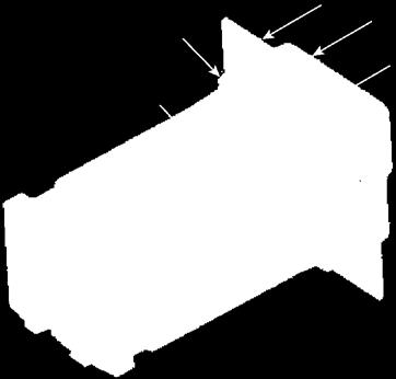
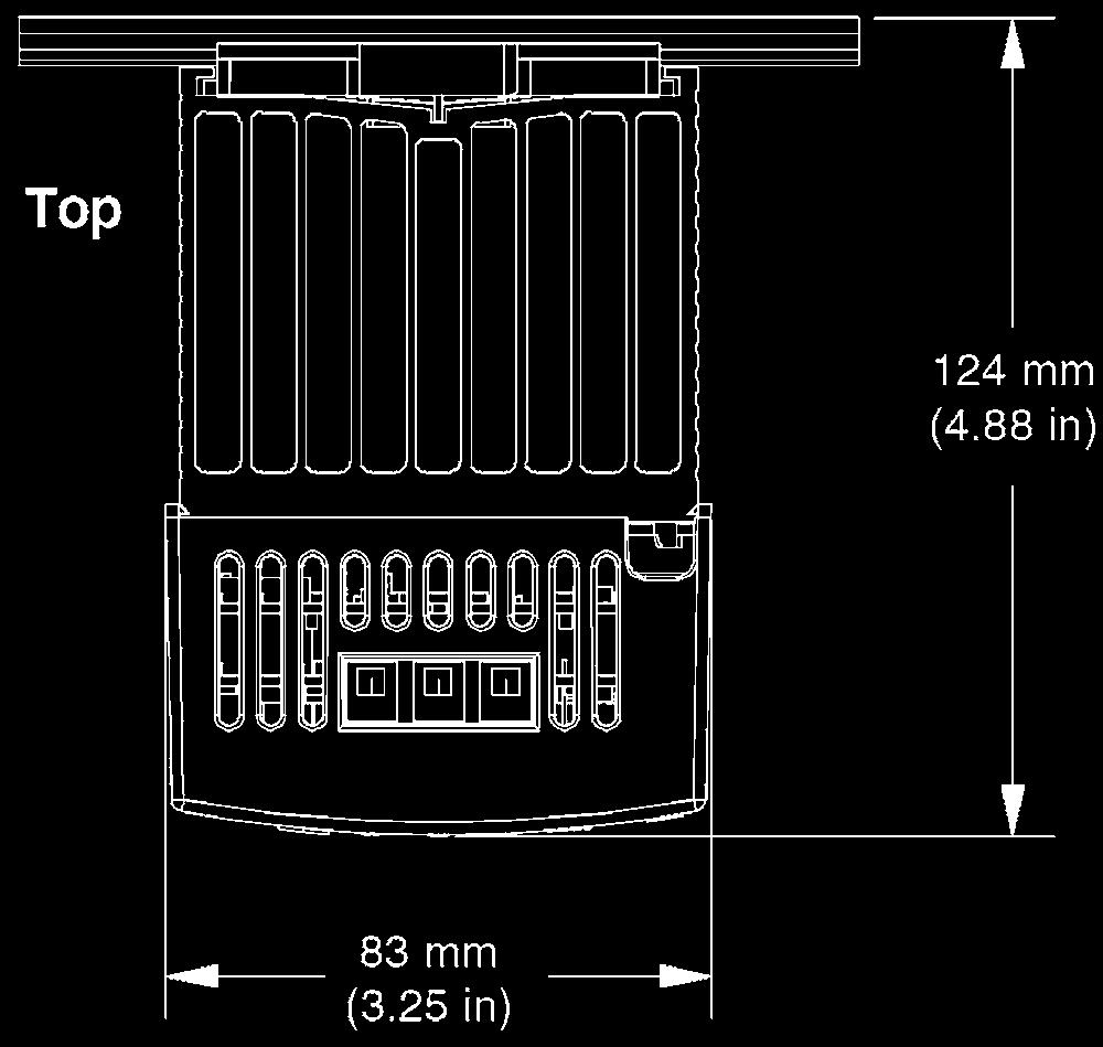


3 DIMENSIONS Controller Relay (for N size pumps only) MOUNTING COLLAR CASE PANEL BEZEL GASKET SECTION TSM ISSUE F PAGE 3 OF 10


4 INSTALLATION Controller Assembly 1. Make the panel cutout using the mounting template dimensions shown in Figure Insert the case assembly into the panel cutout. 3. While pressing the case assembly firmly against the panel, slide the mounting collar over the back of the controller. If the installation does not require a NEMA 4X (UL50, IP66) seal, simply slide together until the gasket is compressed. Removing The Mounted Controller From Its Case DANGER All electrical power to the controller and controlled circuits must be disconnected before removing the controller from the front panel or disconnecting other wiring. Failure to follow these instructions may cause an electrical shock and/or sparks that could cause an explosion in class 1 div. 2 hazardous locations. 1. From the face side of the controller, pull out the tabs on each side until you hear it click. Slide the mounting collar over the back of the controller. 4. For a NEMA 4X (UL50, IP66) seal, alternately place and push the blade of a screwdriver against each of the four corners of the mounting collar assembly. Apply pressure to the face of the controller while pushing with the screwdriver. Don t be afraid to apply enough pressure to properly install the controller. The seal system is compressed more by mating the mounting collar tighter to the front panel. If you can move the case assembly back and forth in the cutout, you do not have a proper seal. The tabs on each side of the mounting collar have teeth that latch into the ridges on the sides of the controller. Each tooth is staggered at a different depth from the front so that only one of the tabs on each side is locked onto the ridge at a time. Note: There is a graduated measurement difference between the upper and lower half of the display to the panel. In order to meet the seal requirements mentioned above, ensure that the distance from the front of the top half of the display to the panel is in. (16 mm) or less, and the distance from the front of the bottom half and the panel is in. (13.3 mm) or less. Pull out the tab on each side until you hear it click. 2. Once the sides are released grab the unit above and below the face with two hands and pull the unit out. Grab the unit above and below the face and pull forward. Returning the Controller to its Case 1. Ensure that the orientation of the controller is correct and slide it back into the housing. The controller is keyed so it should slide easily back in to the case. Do not force it. Verify orientation again if it will not slide back into the case. 2. Using your thumbs push on either side of the controller until both latches click. SECTION TSM ISSUE F PAGE 4 OF 10


5 Relay (for N size pumps only) Assembly: 1. Push the unit in and down to catch the rail hook on top of the rail. 2. Rotate the bottom of the unit toward the rail. 3. The rail clasp will audibly snap into place. If the DIN- A-MITE does not snap into place, check to see if the rail is bent. 4. Mount the cooling fins vertically. Disassembly: 1. Press down on the release tab while rotating the unit up and away from the rail. SECTION TSM ISSUE F PAGE 5 OF 10
6 WIRING For H-QS pumps, the wiring diagram in Figure 2 shows how the controller is wired to the power source, cartridge heaters, ready light, and thermocouple. Figure 4 shows the layout of the terminals on the controller. The terminal descriptions of the controller are given in Table 1. Power Source For N size pumps, the wiring diagram in Figure 3 shows how the controller is wired to the power source, cartridge heaters, relay, ready light, and thermocouple. Figure 4 shows the layout of the terminals on the controller, and Figure 5 shows the layout of the terminals on the relay. The terminal descriptions of the controller are given in Table 1, and the relay terminal descriptions are given in Table 2. NOT READY LIGHT L1 J1 Fuse 15A K1 L2 PID K2 S1 R1 Fuse 15A Heat Cartridges DANGER Always disconnect, lockout, and tag out supply circuits prior to installing. Use National Electric (NEC) or other countryspecific standard wiring and safety practices when wiring and connecting this controller to a power source and to electrical sensors or peripheral devices. Failure to do so may result in damage to equipment and property, and/or injury or death. The installation must comply with standard and local regulations. All wiring should be done by a licensed electrician to meet local codes. Study this manual thoroughly before installing and using the controller. Pay special attention to this section and the parts marked WARNING or DANGER. Should questions or uncertainties arise, please contact your authorized Viking distributor. Proper selection and installation of the thermocouple wiring and cartridge heater wiring is the responsibility of the end user. Refer to the temperature controller manual for instructions. READY LIGHT Controller Thermocouple * FIGURE 2 - WIRING DIAGRAM FOR H-QS SIZE PUMPS NOT READY LIGHT READY LIGHT L1 J1 Power Source Fuse K1 15A Controller 98 S1 PID 99 R1 Thermocouple * FIGURE 3 - WIRING DIAGRAM FOR N SIZE PUMP ONLY L2 K2 Fuse 40A SSR 6 5 Relay Heat Cartridges NOTES: * Thermocouples are polarity sensitive. The negative lead (usually red) must be connected to S1. The extension wire for thermocouples must be of the same alloy as the thermocouple. DANGER Do not put a fuse or switch on the neutral line coming into terminal 3. Failure to follow this guideline could result in personal injury or death. SECTION TSM ISSUE F PAGE 6 OF 10
 99 Common (Controller) CF Not Used CD Not Used K2 Common (Heat Cartridges) CE Not Used T1 Not Used B5 Not Used S1 Negative Thermocouple Lead (Usually red")
7 FIGURE 4 - CONTROLLER TERMINAL LOCATIONS Slot A L1 Normally Open (Not Ready Light) K1 Common (Ready Light / Pump Interlock) J1 L2 Normally Closed (Ready Light) Power Output; Fused (Heat Cartridges) Slot C 98 Power Input; AC; Fused (Controller) 99 Common (Controller) CF Not Used CD Not Used K2 Common (Heat Cartridges) CE Not Used T1 Not Used B5 Not Used S1 Negative Thermocouple Lead (Usually red wire used) D6 Not Used R1 Positive Thermocouple Lead D5 Not Used FIGURE 5 - RELAY TERMINAL LOCATIONS (FOR N SIZE PUMP ONLY) Relay Terminal Definitions 1 Not Used 2 Power Input; AC; Fused (From Power Source) 3 Common 4 Not Used 5 Heater 6 Heater 7 Power Input (From Controller) 8 Common 9-16 Not Used TABLE 2 - RELAY TERMINAL DESCRIPTIONS (FOR N SIZE PUMP ONLY) TABLE 1 - CONTROLLER TERMINAL DESCRIPTIONS NOTES: 1. Input power for the controller must be 240VAC, single phase, 60 Hz or 220VAC, single phase, 50 Hz. 2. Controller terminals a. 18 to 12 AWG wire size for heaters and controller. Use appropriate thermocouple wire for thermocouple and application. b. Torque to 7.0 lb-in (0.8 Nm) c. Wire strip length 0.30 in (7.6 mm). 3. Relay input terminals for use with N size pump only (terminals 7-16) a. 24 to 16 AWG wire size b. Torque to 4.4 lb-in (0.5 Nm) c. Wire strip length of 0.22 in (5.5 mm) 4. Relay line and load terminals for use with N size pump only (terminals 1-6) a. Will accept 18 to 8 AWG wire size b. Torque to 12 lb-in (1.4 Nm) c. Wire strip length 0.25 in (6.35 mm) d. Retorque after 48 hours to minimize wire cold flow e. Retorque terminals every 3 to 6 months f. Ground terminal use spade terminal for No. 8 screw, with upturned lugs g. Attach grounding wire to grounding screw (#6) 5. Maintain electrical isolation between thermocouple analog input 1 (terminals S1 and R1), any digital inputs-outputs, and process outputs 1 and 2 (terminals L1, K1 and L2, K2, respectively) to prevent ground loops. 6. To prevent injury and damage to the controller, do not connect wires to unused terminals. 7. The wires for the heat cartridges can be joined together in a junction box, and a single wire from the junction box can be connected to the controller. 8. The wiring diagram is only valid for standard type J thermocouples and controllers supplied from Viking Pump. 9. For information on the location and installation of the heat cartridges and thermocouple, please see the TSM for your specific pump. The thermocouple will require a fitting adapter which is included with the controller kit in order to mount to the pump. SECTION TSM ISSUE F PAGE 7 OF 10

8 Upper Display In the Home Page, displays the process value, otherwise displays the value of the parameter in the lower display. Zone Display Indicates the controller zone. KEY LAYOUT AND FUNCTIONS Lower Display Indicates the set point or output power value during operation, or the parameter whose value appears in the upper EZ Key display. Not Used NOTE: This controller has been preprogrammed by Viking Pump to lockout many functions to simplify installation and Advance Key operation for customer specified Advances through parameter prompts. electric heat applications. If advanced functionality is Infinity Key required, the user should Press to back up one level, or press and hold for two source their own controller from seconds to return to the Home Page. From the Home a qualified heat control vendor. Page, you can clear alarms and errors if clearable. Temperature Units Indicates whether the temperature is displayed in Fahrenheit or Celsius. Percentage Units Lights when the controller is displaying values as a percentage. Output Activity Number LEDs indicate activity of outputs. A flashing light indicates output activity. #2 indicates when power applied to heaters. Up and Down Arrow Keys In the Home Page, adjusts the set point in the lower display. In other pages, changes the upper display to a higher or lower value, or changes the parameter selection. OPERATION WARNING WARNING Depending on the set point temperature at startup, the controller may deliver power to the heat cartridges and cause them to heat as soon as the controller is turned on. Setting the set point temperature higher than necessary will not make the pump heat any faster and will shorten the life of the heat cartridges. 1. Press and hold the Infinity Key for two seconds to bring up the Home Page. 2. Use the Up and Down Arrow Keys to adjust the set point temperature if necessary. The lower display of the Home Page shows the set point temperature. The set point temperature needs to be slightly higher than the melting point and significantly lower than the flash point or boiling point of the liquid being pumped. 3. To make sure that the liquid within the pump is melted and to avoid damage to the pump, do not start the pump until the set point temperature has been reached. Depending on your setup, there may be a ready light to indicate when the set point has been reached. On the Home Page, the upper display shows the process temperature, and the lower display shows the set point temperature. SECTION TSM ISSUE F PAGE 8 OF 10
9 TROUBLESHOOTING Error Code Description Possible Causes Corrective Action Sensor does not provide a valid signal 1. Thermocouple improperly wired or open 1. Correct wiring or replace thermocouple Error Input to controller No heat action Output does not activate load 1. Output is incorrectly wired 2. Load, power, or fuse is open 3. Set point is incorrect 4. Heat cartridge is burnt out* No display No display indication or LED illumination 1. Power to controller is off 2. Fuse open 3. Breaker tripped 4. Safety interlock switch open 5. Wiring error 6. Incorrect voltage to controller Temperature runaway Device Error Process value continues to increase past set point Controller displays internal malfunction message at power up. 1. Thermocouple reverse wired 2. Controller output wired incorrectly 3. Short in heater 4. Power controller connection to controller defective 5. Controller output defective 1. Correct output wiring 2. Correct fault in system 3. Adjust set point to correct temperature 4. Replace heat cartridge 1. Turn on power 2. Replace fuse between power source and controller 3. Reset breaker 4. Close interlock switch 5. Correct wiring issue 6. Check voltage requirements and apply correct voltage 1. Correct thermocouple wiring (red wire negative) 2. Verify and correct wiring 3. Replace heater 4. Replace or repair power controller 5. Replace or repair controller 1. Controller is defective 1. Replace or repair controller * Use an ohmmeter or multimeter to determine the resistance across the heat cartridge. A burnt out heater will have a reading of infinity ( ) ohms. The customer supplied fuse between the heat cartridges and controller will typically blow when one of the heat cartridges fails TECHNICAL DATA - Controller TECHNICAL DATA - Relay Weight 6.6 oz. (186 g) Supply Voltage 1x (±10%) Frequency 50 or 60 Hz Power Consumption Max 10 VA Fuses Use Max 15 A Terminal Wire Size Use 18 to 12 AWG Terminal Tightening Torque 7 lb-in (0.8 Nm) Max Temperature Ambient ± 3.15 F (1.75 C) Sampling Rates for Input & Output 10 Hz Heater Relay (L2,K2) NO-ARC 15A, Form A Ready Light Relay (L1,K1) Mechanical Relay 5A, Form C Operating Temperature F ( C) Storage Temperature F ( C) Allowable Humidity 0 to 90%; non-condensing Protection Class NEMA 4X/IP66 if installed correctly (see assembly step 4) (indoor use only) Pollution Degree Pollution Degree 2 Back-up Battery Information Allows for data retention upon power failure Battery Type: lithium (recycle properly) Typical Battery Life: three cumulative years of unpowered life at 77 F (25 C) Agency Approvals UL Listed to UL File E UL Reviewed to CSA C22.2 No UL 50 Type 4X (indoor use only) FM Class 3545 File temperature limit switches CE, RoHS, and W.E.E.E. compliant Suitable for use in Class 1, Div 2, Groups A, B, C and D or non-hazardous locations only. Temperature Code T4A UL Listed to ANSI/ISA File E CSA approved; CSA C22. No. 24 File Class UL reviewed to Standard No. CSA C22.2 No. 213-M1987 Weight 1.6 lbs (0.7 kg) Supply Voltage 85V minimum - 660V maximum Frequency 50 or 60 Hz Power Consumption 1.2 watts per amp switched Storage Temperature F ( C) Allowable Humidity 0 to 90%; non-condensing Protection Class IP20 Pollution Degree Pollution Degree 2 Classification Power Control; Installation III Agency Approvals UL 508 Listed and C-UL, File E73741 SECTION TSM ISSUE F PAGE 9 OF 10
10 TECHNICAL SERVICE MANUAL SINGLE CHANNEL CONTROLLER SECTION TSM PAGE 10 OF 10 ISSUE F EU (EUROPEAN UNION) SPECIFICATIONS The controller meets the essential requirements of the following European Union Directives by using the relevant standards shown below to indicate compliance 2004/108/EC Electromagnetic Compatibility Directive Electrical equipment for measurement, control EN and laboratory use- EMC requirements (Industrial Immunity, Class B Emissions). EN A1,A2 Electrostatic Discharge Immunity EN Radiated Field Immunity 10V/M MHz, 3 V/M GHz EN Electrical Fast-Transient/ Burst Immunity EN Surge Immunity EN A1,A2,A3 Conducted Immunity EN Voltage Dips, Short Interruptions and Voltage Variations Immunity EN Harmonic Current Emissions EN Voltage Fluctuations and Flicker SEMI F Specification for Semiconductor Sag Immunity Figure R /95/EC Low-Voltage Directive Safety Requirements of electrical equipment for EN measurement, control and laboratory use. Part 1: General requirements. Compliant with 2002/95/EC RoHS Directive DISMANTLING AND DISPOSAL The enclosure is made of Polycarbonate material. Use proper recycling techniques. Do not throw in trash. When disposing, the parts must be handled and recycled in accordance with local regulations. Per 2002/96/EC W.E.E.E. Directive, please recycle properly. The controller contains a lithium battery that must be recycled properly WARRANTY Viking pumps, strainers and reducers are warranted to be free of defects in material and workmanship under normal conditions of use and service. The warranty period varies by type of product. A Viking product that fails during its warranty period under normal conditions of use and service due to a defect in material or workmanship will be repaired or replaced by Viking. At Viking s sole option, Viking may refund (in cash or by credit) the purchase price paid to it for a Viking product (less a reasonable allowance for the period of use) in lieu of repair or replacement of such Viking product. Viking s warranty is subject to certain restrictions, limitations, exclusions and exceptions. A complete copy of Viking s warranty, including warranty periods and applicable restrictions, limitations, exclusions and exceptions, is posted on Viking s website ( A complete copy of the warranty may also be obtained by contacting Viking through regular mail at Viking Pump, Inc., 406 State Street, Cedar Falls, Iowa 50613, USA. THIS WARRANTY IS AND SHALL BE VIKING S SOLE AND EXCLUSIVE WARRANTY AND IS IN LIEU OF ALL OTHER WARRANTIES, EXPRESS OR IMPLIED, INCLUDING, BUT NOT LIMITED TO, ALL WARRANTIES OF MERCHANTABILITY, FITNESS FOR A PARTICULAR PURPOSE AND NON-INFRINGMENT, ALL OF WHICH OTHER WARRANTIES ARE EXPRESSLY EXCLUDED. THE RIGHTS AND REMEDIES UNDER THIS WARRANTY ARE AND SHALL BE THE SOLE AND EXCLUSIVE RIGHTS AND REMEDIES AGAINST VIKING. EXCEPT FOR THE SPECIFIC LIABILITIES AND OBLIGATIONS PROVIDED UNDER THIS WARRANTY, VIKING SHALL HAVE NO LIABILITY OR OBLIGATION WITH RESPECT TO ANY PRODUCT CLAIMED TO BE DEFECTIVE IN ANY MANNER. UNDER NO CIRCUMSTANCES SHALL VIKING BE LIABLE UNDER THIS WARRANTY OR OTHERWISE FOR SPECIAL, INCIDENTAL, INDIRECT, CONSEQUENTIAL OR PUNITIVE DAMAGES OF ANY KIND, INCLUDING, BUT NOT LIMITED TO, LOST OR UNREALIZED SALES, REVENUES, PROFITS, INCOME, COST SAVINGS OR BUSINESS, LOST OR UNREALIZED CONTRACTS, LOSS OF GOODWILL, DAMAGE TO REPUTATION, LOSS OF PROPERTY, LOSS OF INFORMATION OR DATA, LOSS OF PRODUCTION, DOWNTIME, OR INCREASED COSTS, IN CONNECTION WITH ANY PRODUCT, EVEN IF VIKING HAS BEEN ADVISED OR PLACED ON NOTICE OF THE POSSIBILITY OF SUCH DAMAGES AND NOTWITHSTANDING THE FAILURE OF ANY ESSENTIAL PURPOSE OF ANY PRODUCT. VIKING PUMP, INC. A Unit of IDEX Corporation Cedar Falls, IA USA 12/2016 Viking Pump Inc. All rights reserved
TECHNICAL SERVICE MANUAL
 Electronic copies of the most current TSM issue can be found on the Viking Pump website at www.vikingpump.com TECHNICAL SERVICE MANUAL VIKING HELICAL GEAR REDUCERS A, B, AND C SIZES SECTION PAGE ISSUE
TECHNICAL SERVICE MANUAL
 Electronic copies of the most current TSM issue can be found on the Viking Pump website at www.vikingpump.com TECHNICAL SERVICE MANUAL Viking In-Line Helical Gear Reducers Sizes 11, 21, 31, 35, 41, 51,
TECHNICAL SERVICE MANUAL
 Electronic copies of the most current TSM issue can be found on the Viking Pump website at www.vikingcom TECHNICAL SERVICE MANUAL abrasive liquid pumps SERIES 4625 SIZES f - fh SECTION TSM 410.1 PAGE 1
PRODUCT OBSOLETED 4Q16
 Electronic copies of the most current TSM issue can be found on the Viking Pump website at www.vikingcom TECHNICAL SERVICE MANUAL abrasive liquid pumps SERIES 4625 SIZES f - fh SECTION TSM 410.1 PAGE 1
TECHNICAL SERVICE MANUAL
 Electronic copies of the most current TSM issue can be found on the Viking Pump website at www.vikingpump.com TECHNICAL SERVICE MANUAL GENERAL PURPOSE PUMPS SERIES 32, 432 AND 32E SIZES G - N SECTION TSM
TECHNICAL SERVICE MANUAL
 Electronic copies of the most current TSM issue can be found on the Viking Pump website at www.vikingpump.com TECHNICAL SERVICE MANUAL SECTION TSM 610 Viking Helical Gear Reducers a, b, and c sizes PAGE
TECHNICAL SERVICE MANUAL
 Electronic copies of the most current TSM issue can be found on the Viking Pump website at www.vikingpump.com TECHNICAL SERVICE MANUAL industrial heavy duty motor speed pumps SERIES 4076 AND 4176 SIZES
StarEye. 350 ma version. No control electronics on board
 StarEye 350 ma version No control electronics on board CONTENT 1 PICTURE... 3 1.1 GENERAL... 3 2 DIMENSIONS... 4 3 SAFETY INFORMATION... 5 3.1 SYMBOLS... 5 3.2 PROTECTION FROM ELECTRIC SHOCK... 6 3.3 PROTECTIONS
The Ultimate Smart Grid Solution INSTRUCTION MANUAL
 ECOWISE EW30/1 The Ultimate Smart Grid Solution INSTRUCTION MANUAL Welcome! Congratulations on selecting the ECOWISE unit to manage your energy supply needs. ECOWISE units reduce the amount of electric
CONTENT 1 PICTURE GENERAL... 3
 IP67 CONTENT 1 PICTURE... 3 1.1 GENERAL... 3 2 DIMENSIONS... 4 2.1 SYMBOLS... 5 2.2 PROTECTION FROM ELECTRIC SHOCK... 6 2.3 PROTECTIONS FROM FIRE AND BURNS... 6 2.4 PROTECTION FROM INJURY... 7 2.5 DISPOSING
BE SURE POWER IS DISCONNECTED PRIOR TO INSALLATION! FOLLOW NATIONAL, STATE, AND LOCAL CODES! READ THESE INSTRUCTIONS ENTIRELY BEFORE INSTALLATION!
 INSTALLATION INSTRUCTIONS FOR SYMCOM S MOTORSAVER MODEL 460 BE SURE POWER IS DISCONNECTED PRIOR TO INSALLATION! FOLLOW NATIONAL, STATE, AND LOCAL CODES! READ THESE INSTRUCTIONS ENTIRELY BEFORE INSTALLATION!
TECHNICAL SERVICE MANUAL INSTALLATION, START UP, TROUBLESHOOTING, SERIES SG-04, SG-05 & SG-07 spur gear PUMPS
 Electronic copies of the most current TSM issue can be found on the Viking Pump website at www.vikingpump.com TECHNICAL SERVICE MANUAL SECTION TSM 340 PAGE 1 OF 10 ISSUE G INSTALLATION, START UP, TROUBLESHOOTING,
The Ultimate Smart Grid Solution INSTRUCTION MANUAL
 ECOWISE EW20/1 EW30/1 The Ultimate Smart Grid Solution INSTRUCTION MANUAL Welcome! Congratulations on selecting the ECOWISE unit to manage your energy supply needs. ECOWISE units reduce the amount of electric
DUSTTRAK AEROSOL MONITOR SOLAR POWER KIT MODEL
 DUSTTRAK AEROSOL MONITOR SOLAR POWER KIT MODEL 854060 (USED FOR POWERING ENVIRONMENTAL ENCLOSURE MODELS MODELS 854030, 8535 AND 8537) OPERATION AND MAINTENANCE MANUAL P/N 6008416, REVISION C JUNE 2017
Dimensions 12/800N 12/1200N D. DC to AC Power Inverters. OWNERS MANUAL for Models: OWNERS MANUAL April ISO 9001:2000 Certified Company
 Manufacturer of Dimensions Inverters 4467 White Bear Parkway St. Paul, MN 55110 Phone: 651-653-7000 Fax: 651-653-7600 E-mail: inverterinfo@sensata.com Web: www.dimensions.sensata.com OWNERS MANUAL April
Operator's Manual. Storage System. Ultrasound Probe Cabinet. Manufactured by:
 Storage System Ultrasound Probe Cabinet Operator's Manual Manufactured by: CIVCO Medical Solutions 102 First Street South Kalona, IA 52247 USA 319.248.6757 / 800.445.6741 WWW.CIVCO.COM Copyright 2018 All
Installation Guide Smart-UPS On-Line External Battery Pack XBP48RM1U-LI
 Installation Guide Smart-UPS On-Line External Battery Pack XBP48RM1U-LI Important Safety Messages Read the instructions carefully to become familiar with the equipment before trying to install, operate,
Ordering Information. Specifications. Motor Time Switch H2F-WM. Accessories (Order Separately) Time Specifications. Ratings
 Time Specifications. Ratings") Motor Time Switch H2F-WM CSM_H2F-WM_DS_E_2_1 Weekly ON/OFF Control in 1-h Increments The H2F-WM is a Compact Weekly Time Switch in a DIN -mm Body Equipped with Power Interruption Backup Providing Protection
Motor Time Switch H2F-WM CSM_H2F-WM_DS_E_2_1 Weekly ON/OFF Control in 1-h Increments The H2F-WM is a Compact Weekly Time Switch in a DIN -mm Body Equipped with Power Interruption Backup Providing Protection
TECHNICAL SERVICE MANUAL
 Electronic copies of the most current TSM issue can be found on the Viking Pump website at www.vikingpump.com TECHNICAL SERVICE MANUAL BEHIND THE ROTOR SEAL HEAVY DUTY PUMPS SERIES 4124B AND 4224B CAST
model ps600 Address all communications and shipments to: FEDERAL SIGNAL CORPORATION
 MODEL: PS600 HZ: 60 A model ps600 installation and service manual for federal model ps600 FEDERAL SIGNAL CORPORATION POWER SUPPLY VOLTS: SERIES: 120VAC FEDERAL SIGNAL CORPORATION UNIVERSITY PARK, IL. U.S.A.
miconverter 18-Module Rack-Mount Power Chassis User Manual 38 Tesla, Irvine, CA USA Phone: (949) ; Fax: (949) Page 12
 ; Fax: (949) Page 12") miconverter 18-Module Rack-Mount Power Chassis User Manual Page 12 38 Tesla, Irvine, CA 92618 USA Phone: (949) 250-6510; Fax: (949) 250-6514 General and Copyright Notice This publication is protected by
miconverter 18-Module Rack-Mount Power Chassis User Manual Page 12 38 Tesla, Irvine, CA 92618 USA Phone: (949) 250-6510; Fax: (949) 250-6514 General and Copyright Notice This publication is protected by
Installation Instructions for Eaton Surge Protective
 Contents Description Page PH Model Introduction.... 2 Safety Precautions.... 2 Operation.... 2 Preparation... 2 Installation Procedures... 3 Enclosure Mounting (New Applications - Eaton PH and PV Models)....
MIL-24/2600Q MIL-24/3200DQ
 Manufacturer of Dimensions TM Inverters 4467 White Bear Parkway St. Paul, MN 55110 Phone: 651-653-7000 Fax: 651-653-7600 E-mail: inverterinfo@sensata.com Web: www.dimensions.sensata.com 121473B OWNER'S
TECHNICAL SERVICE MANUAL
 Electronic copies of the most current TSM issue can be found on the Viking Pump website at www.vikingpump.com TECHNICAL SERVICE MANUAL HEAVY-DUTY STAINLESS STEEL PUMPS SERIES 724 AND 4724 SIZES H - LL
DIN-A-MITE C. SCR Power Controller Delivers Up To 80 Amperes in a Compact Package. TOTAL CUSTOMER SATISFACTION 3 Year Warranty. Features and Benefits
 DIN-A-MITE C TOTAL CUSTOMER SATISFACTION 3 Year Warranty SCR Power Controller Delivers Up To 80 Amperes in a Compact Package The DIN-A-MITE C silicon controlled rectifier (SCR) power controller provides
Installation Power Management Unit Battery Cables and Battery Harness
 Installation Power Management Unit Battery Cables and Battery Harness Important Safety Messages SAVE THESE INSTRUCTIONS - This manual contains important instructions that should be followed during installation
PM500. Voltage Regulator User Manual. A Regal Brand. Scan here for other languages.
 PM500 Voltage Regulator User Manual A Regal Brand Scan here for other languages. Introduction The PM500 is an encapsulated electronic voltage regulator intended for use with Marathon Generators PMG system.
OWNERS MANUAL JANUARY 2007 ISO
 Manufacturer of Dimensions TM Inverters 4467 White Bear Parkway St. Paul, MN 55110 Phone: 651-653-7000 Fax: 651-653-7600 E-mail: inverterinfo@sensata.com Web: www.dimensions.sensata.com 121231B OWNERS
DC to AC Power Inverters
 Manufacturer of Dimensions TM Inverters 4467 White Bear Parkway St. Paul, MN 55110 Phone: 651-653-7000 Fax: 651-653-7600 E-mail: inverterinfo@sensata.com Web: www.dimensions.sensata.com ISO 9001:2000 Certified
DC to AC Power Inverters
 Manufacturer of Dimensions TM Inverters 4467 White Bear Parkway St. Paul, MN 55110 Phone: 651-653-7000 Fax: 651-653-7600 E-mail: inverterinfo@sensata.com Web: www.dimensions.sensata.com 121114C OWNERS
QSB (Q-Star) Electronics for QSE Electromagnetic Meter. Owner s Manual TABLE OF CONTENTS
 Electronics for QSE Electromagnetic Meter. Owner s Manual TABLE OF CONTENTS") Owner s Manual QSB (Q-Star) Electronics for QSE Electromagnetic Meter Plain Cover Plate and Pulse-Out Transmitter (QSB) Display Mount Cover Plate (to mount a Q09 Display) and Pulse-Out Transmitter (QSB)
Owner s Manual QSB (Q-Star) Electronics for QSE Electromagnetic Meter Plain Cover Plate and Pulse-Out Transmitter (QSB) Display Mount Cover Plate (to mount a Q09 Display) and Pulse-Out Transmitter (QSB)
User Manual. T6 Tachometer. Online: Telephone: P.O. Box St. Petersburg, Florida 33736
 User Manual T6 Tachometer Online: www.phareselectronics.com Telephone: 727-623-0894 P.O. Box 67251 St. Petersburg, Florida 33736 Table of Contents Overview... 1 Description... 1 Wiring... 1 T6 Tachometer
Hybex Microsample Incubator
 www.scigene.com Hybex Microsample Incubator USER MANUAL Cat. #1057-30-0, 1057-30-2 FOR RESEARCH USE ONLY 470 Lakeside Dr, Ste F, Sunnyvale, CA 94085-4720 USA Tel 408-733-7337 Fax 408-733-7336 techserv@scigene.com
Instruction Manual PC104/PC105 3-PHASE SOCKET TESTER. Check out what else you can get from Martindale:
 Check out what else you can get from Martindale: 17th Edition Testers Accessories Calibration Equipment Continuity Testers Electricians Kits Environmental Products Full Calibration & Repair Service Fuse
VP-4124/VP-4124-E 24/48 VOLT DC SWITCHING POWER SUPPLY
 Issue 5 24/48 VOLT DC SWITCHING POWER SUPPLY INTRODUCTION These instructions provide the specifications, installation and maintenance information for the VP-4124 and VP-4124-E, 24/48 Volt Power Supplies.
SAFETY INFORMATION & INSTALLATION GUIDE RMX Programmable Power Supplies. About the RMX Safety Information & Installation Guide
 SAFETY INFORMATION & INSTALLATION GUIDE RMX Programmable Power Supplies RMX-4120/4121/4122/4123/4124/4125/4126/4127 About the RMX Safety Information & Installation Guide This guide is intended for users
51 & 52 Series II. Users Manual. Thermometer. Test Equipment Depot Washington Street Melrose, MA TestEquipmentDepot.
 51 & 52 Series II Thermometer Test Equipment Depot - 800.517.8431-99 Washington Street Melrose, MA 02176 - TestEquipmentDepot.com Users Manual English September 1999 Rev.2, 11/10 1999-2010 Fluke Corporation,
MaxLite StaxMax LED Flood Lights
 Operating Instructions MaxLite StaxMax LED Flood Lights Input Rating 120V-277V 50/60Hz (347/480v optional) Wet Location Rated IP65 Operating temperature -22⁰F to 105⁰F General Safety Information 1. READ
TECHNICAL SERVICE MANUAL
 Electronic copies of the most current TSM issue can be found on the Viking Pump website at www.vikingpump.com TECHNICAL SERVICE MANUAL HEAVY-DUTY Stainless steel BRACKET MOUNTED PUMPS SERIES 127 AND 4127
i3000s/i2000 Flex AC Current Probe
 i3000s/ AC Current Probe Instruction Sheet Introduction The i3000s 24 Flex, i3000s 36 Flex, and AC Current Probes (the Probe) are used with oscilloscopes, digital multimeters, recorders or data loggers.
TECHNICAL SERVICE MANUAL
 Electronic copies of the most current TSM issue can be found on the Viking Pump website at www.vikingpump.com TECHNICAL SERVICE MANUAL EXTERNAL GEAR PUMPS SERIES GP-425 SECTION TSM 340.3 PAGE 1 OF 8 ISSUE
DALI 650mA LED Driver
 Installation Guide DGLC650C18DD PATENT PENDING REGISTERED DESIGN Designed in Australia to meet Australian Standards and installation conditions DIGINET.NET.AU Diginet Control Systems Pty Ltd ABN 89 095
1000mA - 650mA Phase Dimmable LED Driver
 Installation Guide DGLC1000C25PD 1000mA - 650mA Phase Dimmable LED Driver PATENT PENDING REGISTERED DESIGN Designed in Australia to meet Australian Standards and installation conditions DIGINET.NET.AU
Motorized Stainless 2-Way Valves
 Installation and Operation Manual Motorized Stainless 2-Way Valves Safety Valve ETV Applications WARNING This Heat-Timer valve is strictly an operating valve; it should never be used as a primary limit
 Distributed by: www.jameco.com 1-800-831-4242 The content and copyrights of the attached material are the property of its owner. 51 & 52 Series II Thermometer Users Manual English September 1999 Rev.1,
650mA Phase Dimmable LED Driver
 Installation Guide DGLC650C18PD PATENT PENDING REGISTERED DESIGN Designed in Australia to meet Australian Standards and installation conditions DIGINET.NET.AU Diginet Control Systems Pty Ltd ABN 89 095
ADI-125/750 ADI-125/1500 ADI-125/2500
 Manufacturer of Dimensions TM Inverters 4467 White Bear Parkway St. Paul, MN 55110 Phone: 651-653-7000 Fax: 651-653-7600 E-mail: inverterinfo@sensata.com Web: www.dimensions.sensata.com 121094B OWNERS
PRM-4. Phase Sequence and Motor Rotation Tester. Users Manual. For detailed specifications and ordering info go to
 PRM-4 Phase Sequence and Motor Rotation Tester Users Manual For detailed specifications and ordering info go to www.testequipmentdepot.com PRM-4 Phase Sequence and Motor Rotation Tester English Users Manual
CBC-300 Series & CBC-300C Series Dual Channel Adjust Clutch/Brake Controls
 CBC-300 Series & CBC-300C Series Dual Channel Adjust Clutch/Brake Controls P-269-89-0408 Installation Installation & Operating Instructions Contents Introduction........................... 2 Specifications.........................
Video & Power Over Coax Kit
 VPoC User Manual Video & Power Over Coax Kit 1CH Video Power over Coax w/ 12V DC Receiver Device VPoC24DC-01K VPoC24DC-01 N-42-1 x1 N-41C 4CH / 8CH / 16CH Video Power over Coax Server Kit VPoC24DC-04K
High Frequency SineWave Guardian TM
 High Frequency SineWave Guardian TM 380V 480V INSTALLATION GUIDE FORM: SHF-IG-E REL. January 2018 REV. 002 2018 MTE Corporation High Voltage! Only a qualified electrician can carry out the electrical installation
INSPECTOR LINE LOAD SIMULATOR INSTRUCTION MANUAL TASCO, INC.
 INSPECTOR LINE LOAD SIMULATOR INSTRUCTION MANUAL INS120P TASCO, INC. THIS TESTER IS DESIGNED FOR USE ONLY BY QUALIFIED ELECTRICIANS. IMPORTANT SAFETY WARNINGS mwarning Read and understand this material
A419 Series Electronic Temperature Controls with NEMA 1 or NEMA 4X Watertight Enclosures
 Installation Instructions Issue Date April 8, 2008 A419 Series Electronic Temperature Controls with NEMA 1 or NEMA 4X Watertight Enclosures Application IMPORTANT: The A419 Series Electronic Temperature
OWNERS MANUAL JANUARY 2007 ISO
 Manufacturer of Dimensions TM Inverters 4467 White Bear Parkway St. Paul, MN 55110 Phone: 651-653-7000 Fax: 651-653-7600 E-mail: inverterinfo@sensata.com Web: www.dimensions.sensata.com OWNERS MANUAL JANUARY
A Member of the. Integrated Metering Technologies
 I n s t a l l a t i o n M a n u a l A Member of the Integrated Metering Technologies 1.0 General and Safety Do not install, operate or maintain this flow meter without reading, understanding and followingthe
0.5 s to 30 h (30 s, 3 min, 30 min, 3 h, 30 h)
") Mechatronic Analog Timer H3AM Please read and understand this catalog before purchasing the products. Please consult your OMRON representative if you have any questions or comments. Refer to Warranty and
Mechatronic Analog Timer H3AM Please read and understand this catalog before purchasing the products. Please consult your OMRON representative if you have any questions or comments. Refer to Warranty and
Filtered PWM Speed Control for Permanent Magnet DC Motors
 Instructions for Installation and Operation Filtered PWM Speed Control for Permanent Magnet DC Motors Model 0794 Speed and Direction Control up to 5/8 HP NEMA-1/IP-20 Specifications Product Type:... WPM-2148E1
RS-3 PRO RS-1007 PRO. CAT IV Analog Clamp meter Series. Users Manual. For detailed specifications and ordering info go to
 RS-3 PRO RS-1007 PRO CAT IV Analog Clamp meter Series Users Manual For detailed specifications and ordering info go to www.testequipmentdepot.com RS-3 PRO RS-1007 PRO CAT IV Analog Clampmeter Series English
Patient Care Facility
 ISIMET Patient Care Facility DLA Controller Individual Room Configuration Style 1 W/ Ver 4.41 pcb & Pulse Relay pcb Installation, Operations, Start-up and Maintenance Instructions Meets all Standards for
PolyStat Immersion Circulators
 PolyStat Immersion Circulators Manual P/N U00988 Rev. 06/09/08 Instruction and Operation Manual PolyStat Immersion Circulator Table of Contents Preface Safety Compliance... 2 Unpacking... 2 Warranty...
REDI-LINE. Rugged, Reliable, DC to AC Power Conversion ELECTRIC GENERATORS USER'S GUIDE. KARAM A.L.
 REDI-LINE ELECTRIC GENERATORS USER'S GUIDE Rugged, Reliable, DC to AC Power Conversion KARAM A.L. www.alternatorstarter.com 1-888-515-2726 REDI-LINE ELECTRIC GENERATOR MODEL INPUT ACTUAL OUTPUT ACTUAL
Drug Testing Labs. Style 2 W/ Ver 4.41 pcb & Pulse Relay pcb(s) Installation, Operations, Start-up and Maintenance Instructions
 Installation, Operations, Start-up and Maintenance Instructions") ISIMET Drug Testing Labs DLA Controller Style 2 W/ Ver 4.41 pcb & Pulse Relay pcb(s) Installation, Operations, Start-up and Maintenance Instructions Meets all Standards for Canadian Industrial Control
ISIMET Drug Testing Labs DLA Controller Style 2 W/ Ver 4.41 pcb & Pulse Relay pcb(s) Installation, Operations, Start-up and Maintenance Instructions Meets all Standards for Canadian Industrial Control
M T E C o r p o r a t i o n. dv/dt Filter. Series A VAC USER MANUAL PART NO. INSTR REL MTE Corporation
 M T E C o r p o r a t i o n dv/dt Filter Series A 440-600 VAC USER MANUAL PART NO. INSTR - 019 REL. 041119 2004 MTE Corporation IMPORTANT USER INFORMATION NOTICE The MTE Corporation dv/dt Filter is designed
MaxLite LED Linear HighBay Fixtures
 Operating Instructions MaxLite LED Linear HighBay Fixtures General Safety Information To reduce the risk of death, personal injury or property damage from fire, electric shock, falling parts, cuts/abrasions,
Thyristor power controller TE10A. Burst-firing Single-cycle Advanced Single-cycle
 Thyristor power controller TE10A Burst-firing Single-cycle Advanced Single-cycle Control of short-wave infrared elements and loads of constant resistance up to 20kW User Manual Copyright Eurotherm Automation
i400s Calibration Information Introduction
 i400s AC Current Clamp Introduction XWWarning To avoid electric shock or injury, do not perform the performance tests or calibration procedures unless you are qualified to do so. The information provided
Charging Station - Instructions For Use
 Charging Station - Instructions For Use READ THE HYBRESIS CONTROLLER AND PATCH INSTRUCTIONS FOR USE FOR ADDITIONAL IMPORTANT INFORMATION. REF: 199586 GLOSSARY OF SYMBOLS This device may contain one or
A6Z OPERATING MANUAL
 A6Z OPERATING MANUAL TABLE OF CONTENTS Introduction... p. 2 Features... p. 2 Description... p. 3 Theory of Operation... p. 3 Installation... p. 4 Electrical Connections... p. 5 Options... p. 6 Warranty.p.
Operation Key D4BS - K Head Mounting Direction F: Four mounting directions possible (front-side mounting at shipping)
") Safety-door Switch D4BS The Special Activates a Direct Opening Mechanism to Open the Contacts and Shut Off Control Circuits when Protective Doors Are Opened on Machine Tools or Other Equipment CSM_D4BS_DS_E_6_1
Safety-door Switch D4BS The Special Activates a Direct Opening Mechanism to Open the Contacts and Shut Off Control Circuits when Protective Doors Are Opened on Machine Tools or Other Equipment CSM_D4BS_DS_E_6_1
WF-5100 Series True Sine Wave Inverters
 Operator s Manual WF-5100 Series True Sine Wave Inverters WF-9900 Series WF-5118 WF-5120 ( The Inverter model number is located on the label on top of the enclosure) Distributed in the U.S.A. and Canada
C1XP Series. Models: C1XP01-115AC C1XP03-115AC C1XP03-D240AC USER MANUAL
 C1XP Series Models: C1XP01-115AC C1XP03-115AC C1XP03-D240AC USER MANUAL Copyright 2013 by Minarik Drives All rights reserved. No part of this document may be reproduced or transmitted in any form without
MM-AVR UPS Series User s Manual
 MM-AVR UPS Series User s Manual TABLE OF CONTENTS Safety Instructions... 2 Description... 2 Determining Power Requirements... 3 Hardware Installation Guide... 3 Battery Replacement Instructions... 4 LED
Model Number Structure
 Solid State Relays CSM OEE_DS_E_1_2 Extremely Thin Relays Integrated with Heat Sinks Downsizing achieved through optimum design of heat sink. Mounting possible via screws or via DIN track. Close mounting
A Member of the. Integrated Metering Technologies
 I n s t a l l a t i o n M a n u a l A Member of the Integrated Metering Technologies 1.0 General and safety Do not install, operate or maintain this flow meter without reading, understanding and followingthe
TRAC-Station BT Installation Instructions
 TRAC-Station BT Installation Instructions P/N 10103024P1 November 2011 2011 UTC Fire & Security. All rights reserved. Introduction This is the Supra TRAC-Station BT Installation Instructions. Read these
SUNC1200 / ITEM #40882 SUBMERSIBLE UTILITY PUMP OPERATIONS MANUAL
 SUNC1200 / ITEM #40882 SUBMERSIBLE UTILITY PUMP OPERATIONS MANUAL WWW.SUNRUNNERPOOL.COM Performance Model HP GPH of Water @ Total Feet Of Lift 0 ft. 5 ft. 10 ft. 15 ft. 20 ft. 25 ft. Max. Lift SUNC1200
MAINFRAME HOT RUNNER TEMPERATURE CONTROL SYSTEMS. Instruction Manual
 MAINFRAME HOT RUNNER TEMPERATURE CONTROL SYSTEMS Instruction Manual Copyright, Athena Controls, Inc., 2006 Printed in USA CompuStep is a registered trademark of Athena Controls, Inc. SafeChange is a trademark
201A-9 INSTALLATION INSTRUCTIONS. Revision A1 Rapid City, SD, USA, 01/2010
 INSTALLATION INSTRUCTIONS Revision A1 Rapid City, SD, USA, 01/2010 MODELS 201A 201A-9 2880 North Plaza Drive, Rapid City, South Dakota 57702 (800) 843-8848 (605) 348-5580 fax (605) 348-5685 BE SURE POWER
UNITS Units are designated by the unmounted pump model numbers followed by a letter indicating drive style.
 Electronic copies of the most current TSM issue can be found on the Viking Pump website at www.vikingpump.com TECHNICAL SERVICE MANUAL UNIVERSAL SEAL HEAVY DUTY PUMPS SERIES 124A/AE, 4124A/AE, 124E, 224A,
VCPR. A Portable Device for Remotely Racking VCP-W Circuit Breakers. User s Manual
 VCPR A Portable Device for Remotely Racking VCP-W Circuit Breakers User s Manual MarTek Ltd. RAKTEK User s Manual Model VCPR 1.0 Arc-blast Hazards 2.0 Application Information 3.0 General Safety Information
Switching DC Power Supply
 99 Washington Street Melrose, MA 02176 Phone 781-665-1400 Toll Free 1-800-517-8431 Visit us at www.testequipmentdepot.com Model 1693, 1694 Switching DC Power Supply INSTRUCTION MANUAL 1 Safety Summary
Power. On Your Terms.
 Power. On Your Terms. 10 YEAR LIMITED WARRANTY PHI 1310 TM 1 SIMPLIPHI POWER, INC. REV102016 10 YEAR LIMITED WARRANTY: PHI 1310 TM LIMITED PRO-RATED WARRANTY COVERAGE The SimpliPhi Power PHI 1310 as supplied
INSTALLATION/OWNER'S MANUAL DP " Woofer in Enclosure
 INSTALLATION/OWNER'S MANUAL DP1000 10" Woofer in Enclosure Installation Thank you for purchasing the DP1000 10" Woofer with enclosure. Although Dual has attempted to make sure all of the information contained
Compact System NRGS 11-2 NRGS Original Installation Instructions English
 Compact System NRGS 11-2 NRGS 16-2 EN English Original Installation Instructions 810366-05 1 Contents Important Notes Page Usage for the intended purpose...4 Safety note...4 LV (Low Voltage) Directive
RK Standby Battery Operator s Manual
 49-8104RK Standby Battery Operator s Manual Part Number: 71-0118RK Revision: C Released: 8/4/17 www.rkiinstruments.com Product Warranty RKI Instruments, Inc. warrants gas alarm equipment sold by us to
DRB-1 Series Instruction Manual
 Instruction Manual BEFORE USING THE POWER SUPPLY UNIT Pay attention to all warnings and cautions before using the unit. Incorrect usage could lead to an electrical shock, damage to the unit or a fire hazard.
WF-5110R True Sine Wave Inverter
 Operator s Manual WF-5110R True Sine Wave Inverter WF-9900 Series WF-5110R ( The Inverter model number is located on the label on top of the enclosure) Distributed in the U.S.A. and Canada by ARTERRA DISTRIBUTION
Operation Manual. English. APC Smart-UPS VA 3U Rack and Stack Uninterruptible Power Supply 230 Vac , Revision 1 12/00
 Operation Manual English APC Smart-UPS 1400 VA 3U Rack and Stack Uninterruptible Power Supply 230 Vac 990-1049, Revision 1 12/00 1: OPERATION INDICATORS AND CONTROLS ON THE SMART-UPS The APC Uninterruptible
VP-6124/VP-6124-E 24 VOLT DC SWITCHING POWER SUPPLY
 Issue 6 VP-6124/VP-6124-E 24 VOLT DC SWITCHING POWER SUPPLY INTRODUCTION These instructions provide the specifications, installation and maintenance information for the VP-6124 and VP-6124-E, 24Volt Power
Model C230 Pump Controller
 MANUAL Model C230 Earthsafe Systems, Inc. 7553 S. Madison Willowbrook, IL 60527 T: (630) 794-5100 F: (630) 794-5106 info@earthsafe.com www.earthsafe.com March 1, 2010 The information contained herein is
FHC-1D user manual. Features
 Phason The Fan and Heater Control (FHC-1D) automatically controls the temperature in a room by adjusting the speed of variable speed fans and controlling a heater interlock. When the temperature is at
CTFRP Series Power Supplies
 CTFRP Series Power Supplies Ferroresonant Non-Standby Power Supplies User Manual Myers Power Products 6/2013 CTFRP Series Manual Chapter 1 General Information The Myers CTFRP Series Power Supply provides
A165E CSM_A165E_DS_E_11_2
 Emergency Stop Switch (16-dia.) CSM DS_E_11_2 Separate Construction with Minimal Depth Direct opening mechanism to open contacts in emergencies, such as when they are welded. Conforms to EN 6947-5-5. Includes
362 Clamp Meter. Users Manual
 362 Clamp Meter Users Manual PN 3622678 August 2010, Rev. 1, 4/13 2010, 2013 Fluke Corporation. All rights reserved. Printed in China. Specifications are subject to change without notice. All product names
StormPro BA Series Sump Pump
 Page 1 of 8 Marks & Meanings DANGER: Keep the pump equipment out of the reach of children! Warns that the failure to follow the directions given could cause serious risk to individuals or objects. WARNING:
RK Standby Battery Operator s Manual
 49-8103RK Standby Battery Operator s Manual Part Number: 71-0117RK Revision: 0 Released: 8/18/08 www.rkiinstruments.com Product Warranty RKI Instruments, Inc., warrants gas alarm equipment sold by us to
D4BS CSM_D4BS_DS_E_8_4
 Safety-door Switch CSM DS_E_8_4 The Special Activates a Direct Opening Mechanism to Open the Contacts and Shut Off Control Circuits when Protective Doors Are Opened on Machine Tools or Other Equipment
P. D. Q. Automatic Burnout Furnaces. 115 and 230-volt Models OPERATOR S MANUAL
 P. D. Q. Automatic Burnout Furnaces 115 and 230-volt Models OPERATOR S MANUAL TABLE OF CONTENTS Introduction... 3 Warranty... 3 Safety Instructions........................................................
BT403. A Geno Technology, Inc. (USA) brand name. BT-300 Power Supply. Cat. No. BT
 brand name. BT-300 Power Supply. Cat. No. BT") BT403 A Geno Technology, Inc. (USA) brand name BT-300 Power Supply Cat. No. BT403 1-800-628-7730 1-314-991-6034 info@btlabsystems.com WARNING... 3 SAFETY INFORMATION... 3 ENVIRONMENTAL CONDITIONS... 4
BT403 A Geno Technology, Inc. (USA) brand name BT-300 Power Supply Cat. No. BT403 1-800-628-7730 1-314-991-6034 info@btlabsystems.com WARNING... 3 SAFETY INFORMATION... 3 ENVIRONMENTAL CONDITIONS... 4
The following table shows the symbols used on the product and/or in this manual. Hazardous Voltage. Risk of electric shock.
 i6000s Flex AC Current Probe Instruction Sheet Introduction The i6000s 24 Flex and i6000s 36 Flex AC Current Probes (hereafter referred to as the Probes ) are used with oscilloscopes, digital multimeters,