JTM Series Machine Screw Jacks (Classic Design)
|
|
|
- Gabriel Cooper
- 5 years ago
- Views:
Transcription
1 JTM Series Machine Screw Jacks (Classic Design) -1-
2 Contents Introduction... 3 Order Code General Technical Data... 8 Permissible Buckling Force Performance Tables Assembly Drawing Dimensions Configuration of Screw Jack System Technical Supports Operation and Maintenance Manual Frequently Asked Questions About Us Contact Us
3 Introduction Jacton JTM Series Machine Screw Jacks in classic design (also known as a classic type screw jacks, a classic design screw jack, a classic worm gear screw jack) are usedfor pushing, pulling, lifting, lowering, open, closing, traversing and swinging applications. Due to the classic design, you don't need to attach any construction elements to the housing. In the absence of vibration load, they have self locking and precisely position loads, will hold loads without backdriving, and no need any brake mechanism or locking system. Can be mounted in any attitude. Generally maintenance free. The JTM series machine screw jacks are available in 6 sizes from JTM10 to JTM200, start from a load capacity of 10 kn and can lift up to 200 kn. Customized 300 kn, 500 kn, 750 kn, 1000 kn load capacity jacks. Each with a translating screw version (translating screw jacks), keyed screw for anti-rotation version (keyed screw jacks) and a rotating screw with travelling nut version (rotating screw jacks). Worm (or input shaft) is right angled drives to the lifting screw by a hand wheel with crank handle rotate (manual screw jack) or by a motor drive (motorized screw jack). The JTM series machine screw jacks can be applied either individually use or combined into a lifting system, linked by connecting shafts, couplings, bevel gearboxes, c-face motor adapters, limit switches, geared motor and couplings etc. Can be used as alternatives to hydraulic and pneumatic systems. The JTM series machine screw jacks incorporates a heat treatment standard C45 steel worm shaft which drives a high strength bronze worm gear. The worm shaft is supported on anti-friction tapered roller bearings with external seals provided to prevent loss of lubrication. Lubrication with synthetic grease ep2 lithium grease. The worm gear is supported on anti-friction tapered roller bearings. Rotation of the worm gear causes the acme thread lifting screw to translate or rotate, depending upon jack configuration. The jack housing is made of ductile iron and proportioned to support the rate capacity of the unit. The lifting screw is made of standard C45 steel. Upright and inverted type JTM series machine screw jacks. Standard acme screw end types such as I=top plate (fixing flange), II=clevis end (pivot bearing end), III=plain end, IV=threaded end, VI=fork end, VII=rod end. Accessories includes Couplings, Universal joints, Telescopic universal joints, Connecting shafts, Hand wheels, Pillow blocks, Flange blocks, Rod ends, Linear guides and bearings, spring covers, Bellows boot, Protection tubes, Trunnion adapter plates and trunnion mounting brackets, Motor flanges, Worm gear reducers, Helical gear reducers, Electric motors, Stepper motors, Servo motors, DC motors, encoders, limit switches, inverters, Position indicators, Stop nuts, Safety nuts. -3-

4 Order Code JTM100 - US H - II - C - PP Sizes JTM10, JTM25, JTM50, JTM100, JTM150, JTM Configuration and Designs US = Upright Translating Screw Design UK = Upright Keyed Screw Design UR = Upright Rotating Screw Design IS = Inverted Translating Screw Design IK = Inverted Keyed Screw Design IR = Inverted Rotating Screw Design Note: The trapezoidal screw of a translating screw design jack must be attached to the load (guided) which prevents the trapezoidal screw from rotating. Add linear guides, rails or rolls are recommended. Note: If your application involves a load which is unattached, unguided or theloadisfree to rotate and not translate, then a keyed screw design jack are required to prevent trapezoidal screw rotation (not recommended) 3. Stroke (mm) There are no standard travel length and all JTM series machine screw jacks travel length are built with customers required. Note: If compressive loads, must consider the trapezoidal screw permissible buckling load. -4-

5 4. Gear Ratios High Travel (mm), Slow Travel (mm), Model Ratio Eff. % Per Turn of Ratio Eff.% Per Turn of Input Shaft Input Shaft JTM10 5: : JTM25 6: : JTM50 6: : JTM100 8: : JTM150 8: : JTM200 8: : Screw End Conditions Standard trapezoidal screw end conditions include I=top plate, II=clevis end, III=plain end, IV=threaded end, VI=fork end, VII=rod end, and no screw end with full threads trapezoidal screw. -5-

6 6. Worm (Input Shaft) Types & Motor Flange Input Types A=Left side shaft B=Right side shaft C=Double input shaft M1= Left side shaft, Right side motor flange M2= Right side motor flange M3= Right side shaft, Left side motor flange M4= Left side motor flange Note: Motor flange input types, if need to purchase the motor from us, your purchase orders must be marked. Otherwise, we only sale screw jack with motor flange. -6-

7 7. Screw Jack Accessories JTM series machine screw jacks with a comprehensive range of accessories like FC=Flex couplings, UJ=Universal joints, TUJ=Telescopic universal joints, CS=Connecting shafts, HW=Hand wheels, PB=Pillow blocks, FB=Flange blocks, RE=Rod ends, LSB=Linear shafts and bearings, LGB=Linear guides and bearings, TSC=Telescopic spring covers, BB=Bellows boot, PP=Protection tubes, TAP=Trunnion adapter plates, TMB=Trunnion mounting brackets, MF=Motor flanges, WGR=Worm gear speed reducers, HGR=Helical gear reducers, EM=Single phase or three phase induction motors, STM=Stepper motors, SEM=Servo motors, DCGM=DC geared motors, REN=Rotary encoders, LS=Travel limit switches, FIN=Frequency inverters, PIN=Position indicators, SN=Stop nuts, TN=Travel nuts, SNU=Safety nuts. -7-
8 General Technical Data Model JTM10 JTM25 JTM50 JTM100 JTM150 JTM200 Max. Static loads (kn) Screw sizes (mm) Tr Tr Tr 26x5 Tr 40x8 Tr 50x10 Tr 65x12 20x4 55x10 Gear ratio-h 5:1 6:1 6:1 8:1 8:1 8:1 Travel (mm), per turn of input shaft-h Eff. %-H Gear ratio-l 20:1 24:1 24:1 24:1 24:1 24:1 Travel (mm), per turn of input shaft-l Eff. %-L Idling torque (N.m) Max. permissible input power (kw)-h Max. permissible input power (kw)-l Max. permissible torque (N.m) of worm Required torque (N.m) of worm at max. Loads-H Required torque (N.m) of worm at max. Loads-L Rotational torque (N.m) of screw at max. loads H: High Ratio, L: Slow Ratio -8-


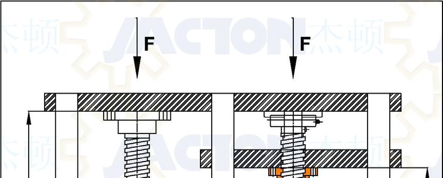
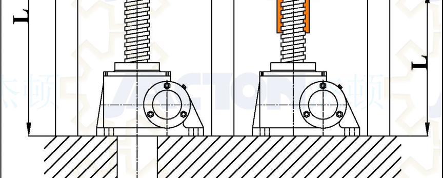
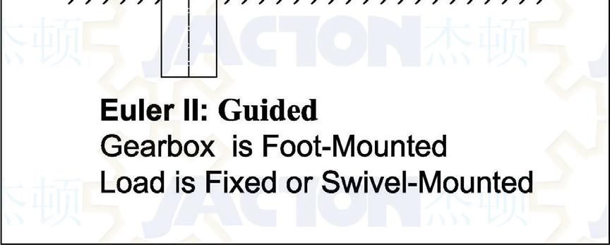
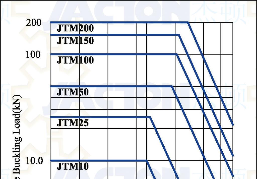
9 Permissible Buckling Force Thin trapezoidal screws may buckle sideways when subjected to compressive loads. Before the permissible compressive force is defined for the trapezoidal screw, allowance must be made for safety factors as appropriate to the installation. -9-
10 -10-

11 -11-

, 1st Floor,")
12 China Sales: Jacton Industry Co.,Ltd (VAT Number: X3), 1st Floor, Buildinig G, No.5, Hengzhong Road,
13 Performance Tables JTM10 Tr 20x4 1. Conditions: within 20% running time/60 minutes or within 30% running time/10 minutes, 20 C ambient temperature. 2. Note: Number of synchronizing jacks which can be connected on the same line is limited by input shaft strength. Refer to the maximum allowable input shaft torque on the above table. 3. Relative humidity: 85% or less (no dew condensation). 4. Operating ambient atmosphere: Indoor Environment (Indoor room where rain and water cannot enter. Dust volume should be normal). 5. Selection of screw jacks using above figures should only be carried out in consultation with Jacton engineers. -13-
14 JTM25 Tr 26x5 1. Conditions: within 20% running time/60 minutes or within 30% running time/10 minutes, 20 C ambient temperature. 2. Note: Number of synchronizing jacks which can be connected on the same line is limited by input shaft strength. Refer to the maximum allowable input shaft torque on the above table. 3. Relative humidity: 85% or less (no dew condensation). 4. Operating ambient atmosphere: Indoor Environment (Indoor room where rain and water cannot enter. Dust volume should be normal). 5. Selection of screw jacks using above figures should only be carried out in consultation with Jacton engineers. -14-
15 JTM50 Tr 40x8 1. Conditions: within 20% running time/60 minutes or within 30% running time/10 minutes, 20 C ambient temperature. 2. Note: Number of synchronizing jacks which can be connected on the same line is limited by input shaft strength. Refer to the maximum allowable input shaft torque on the above table. 3. Relative humidity: 85% or less (no dew condensation). 4. Operating ambient atmosphere: Indoor Environment (Indoor room where rain and water cannot enter. Dust volume should be normal). 5. Selection of screw jacks using above figures should only be carried out in consultation with Jacton engineers. -15-
16 JTM100 Tr 50x10 1. Conditions: within 20% running time/60 minutes or within 30% running time/10 minutes, 20 C ambient temperature. 2. Note: Number of synchronizing jacks which can be connected on the same line is limited by input shaft strength. Refer to the maximum allowable input shaft torque on the above table. 3. Relative humidity: 85% or less (no dew condensation). 4. Operating ambient atmosphere: Indoor Environment (Indoor room where rain and water cannot enter. Dust volume should be normal). 5. Selection of screw jacks using above figures should only be carried out in consultation with Jacton engineers. -16-
. 4.")
17 JTM150 Tr 55x10 1. Conditions: within 20% running time/60 minutes or within 30% running time/10 minutes, 20 C ambient temperature. 2. Note: Number of synchronizing jacks which can be connected on the same line is limited by input shaft strength. Refer to the maximum allowable input shaft torque on the above table. 3. Relative humidity: 85% or less (no dew condensation). 4. Operating ambient atmosphere: Indoor Environment (Indoor room where rain and water cannot enter. Dust volume should be normal). 5. Selection of screw jacks using above figures should only be carried out in consultation with Jacton engineers. -17-
18 JTM200 Tr 65x12 1. Conditions: within 20% running time/60 minutes or within 30% running time/10 minutes, 20 C ambient temperature. 2. Note: Number of synchronizing jacks which can be connected on the same line is limited by input shaft strength. Refer to the maximum allowable input shaft torque on the above table. 3. Relative humidity: 85% or less (no dew condensation). 4. Operating ambient atmosphere: Indoor Environment (Indoor room where rain and water cannot enter. Dust volume should be normal). 5. Selection of screw jacks using above figures should only be carried out in consultation with Jacton engineers. -18-


19 Assembly Drawing Dimensions JTM10 Tr 20x4 Note: dimensions are subject to change without notice. 1. This dimension refers to the closed height and represents a minimum. It must be increased if bellows and boots are used. 2. About 2D Autocad dwg, dxf assembly drawing dimensions, and 3D stp, step, model, igs, prt or catpart assembly drawings, please contact Jacton sales engineers directly. -19-
20 JTM25 Tr 26x5 Note: dimensions are subject to change without notice. 1. This dimension refers to the closed height and represents a minimum. It must be increased if bellows and boots are used. 2. About 2D Autocad dwg, dxf assembly drawing dimensions, and 3D stp, step, model, igs, prt or catpart assembly drawings, please contact Jacton sales engineers directly. -20-

21 JTM50 Tr 40x8 Note: dimensions are subject to change without notice. 1. This dimension refers to the closed height and represents a minimum. It must be increased if bellows and boots are used. 2. About 2D Autocad dwg, dxf assembly drawing dimensions, and 3D stp, step, model, igs, prt or catpart assembly drawings, please contact Jacton sales engineers directly. -21-

22 JTM100 Tr 50x10 Note: dimensions are subject to change without notice. 1. This dimension refers to the closed height and represents a minimum. It must be increased if bellows and boots are used. 2. About 2D Autocad dwg, dxf assembly drawing dimensions, and 3D stp, step, model, igs, prt or catpart assembly drawings, please contact Jacton sales engineers directly. -22-

23 JTM150 Tr 55x10 Note: dimensions are subject to change without notice. 1. This dimension refers to the closed height and represents a minimum. It must be increased if bellows and boots are used. 2. About 2D Autocad dwg, dxf assembly drawing dimensions, and 3D stp, step, model, igs, prt or catpart assembly drawings, please contact Jacton sales engineers directly. -23-


24 JTM200 Tr 65x12 Note: dimensions are subject to change without notice. 1. This dimension refers to the closed height and represents a minimum. It must be increased if bellows and boots are used. 2. About 2D Autocad dwg, dxf assembly drawing dimensions, and 3D stp, step, model, igs, prt or catpart assembly drawings, please contact Jacton sales engineers directly. -24-


25 Configuration of Screw Jack System Two Screw Jacks Lifting System Two Screw Jacks Lifting System Configuration: * I - Configuration: two screw jacks arrangement, three flexible couplings, one connecting shaft, one motor or one handwheel. * L - Configuration: two screw jacks arrangement, one 3 way bevel gearbox, four flexible couplings, one connecting shaft, one motor or one handwheel. * T - Configuration: two screw jacks arrangement, one 3 way bevel gearbox, five flexible couplings, two connecting shafts, one motor or one handwheel. * TI - Configuration: two screw jacks arrangement, one 3 way bevel gearbox, five flexible couplings, two connecting shafts, one motor or one handwheel. Note: when connecting shafts length is exceed maximum distance of between supports, pillow blocks are required. Note: 2-jacks lifting systems efficiency 95%. When calculations, don't ignore bevel gearbox efficiency 94%, helical gearmotors efficiency 94%, idling torque etc -25-


26 Three Screw Jacks Lifting System Three Screw Jacks Lifting System Configuration: * I: three jacks, five couplings, two connecting shafts, one motor. * L: three jacks, one bevel gearbox, six couplings, two connecting shafts, one motor. * T: three jacks, one bevel gearbox, six couplings, two connecting shafts, one motor. * TL: three jacks, one bevel gearbox, six couplings, two connecting shafts, one motor. * TI: three jacks, one bevel gearbox, seven couplings, three connecting shafts, one motor. * TT: three jacks, two bevel gearboxes, nine couplings, four connecting shafts, one motor. Note: when connecting shafts length is exceed maximum distance of between supports, pillow blocks are required. Note: 3-jacks lifting systems efficiency 90%. When calculations, don't ignore bevel gearbox efficiency 94%, helical gearmotors efficiency 94%, idling torque etc -26-


27 Four Screw Jacks Lifting System Four Screw Jacks Lifting System Configuration: * U - Configuration: four screw jacks arrangement, three 3-way bevel gear boxes, eleven flexible couplings, four connecting shafts, one motor or one handwheel. * H - Configuration: four screw jacks arrangement, three 3-way bevel gear boxes, thirteen flexible couplings, six connecting shafts, one motor or one handwheel. * HI - Configuration: four screw jacks arrangement, two 3-way bevel gear boxes, eleven flexible couplings, five connecting shafts, one motor or one handwheel. * UI - Configuration: four screw jacks arrangement, two 3-way bevel gear boxes, nine flexible couplings, three connecting shafts, one motor or one handwheel. Note: when connecting shafts length is exceed maximum distance of between supports, pillow blocks are required. Note: 4-jacks lifting systems efficiency 85%. When calculations, don't ignore bevel gearbox efficiency 94%, helical gearmotors efficiency 94%, idling torque etc -27-


28 Four Screw Jacks Lifting System Four Screw Jacks Lifting System Configuration: *T- Configuration: four screw jacks arrangement, one 3-way bevel gear box, nine flexible couplings, four connecting shafts, one motor or one handwheel. *TT- Configuration: four screw jacks arrangement, one 4-way bevel gear box, nine flexible couplings, four connecting shafts, one motor or one handwheel. Note: when connecting shafts length is exceed maximum distance of between supports, pillow blocks are required. Note: 4-jacks lifting systems efficiency 85%. When calculations, don't ignore bevel gearbox efficiency 94%, helical gearmotors efficiency 94%, idling torque etc. -28-


29 Six Screw Jacks Lifting System Six Screw Jacks Lifting System Configuration: *H-Configuration: six screw jacks arrangement, three 3-way bevel gearboxes, fifteen flexible couplings, six connecting shafts, one motor or one handwheel. *U-Configuration: six screw jacks arrangement, three 3-way bevel gearboxes, fifteen flexible couplings, six connecting shafts, one motor or one handwheel. *HH- Configuration: six screw jacks arrangement, three 4-way bevel gearboxes, seventeen flexible couplings, eight connecting shafts, one motor or one handwheel. Note: when connecting shafts length is exceed maximum distance of between supports, pillow blocks are required. Note: 6-jacks lifting systems efficiency 80%. When calculations, don't ignore bevel gearbox efficiency 94%, helical gearmotors efficiency 94%, idling torque etc. -29-


30 Eight Screw Jacks Lifting System Eight Screw Jacks Lifting System Configuration: *H-Configuration: eight screw jacks arrangement, three 3-way bevel gearboxes, twenty-one flexible couplings, ten connecting shafts, one motor or one handwheel. *HH- Configuration: eight screw jacks arrangement, seven 3-way bevel gearboxes, twenty-nine flexible couplings, fourteen connecting shafts, one motor or one handwheel. Note: when connecting shafts length is exceed maximum distance of between supports, pillow blocks are required. Note: 8-jacks lifting systems efficiency 80%. When calculations, don't ignore bevel gearbox efficiency 94%, helical gearmotors efficiency 94%, idling torque etc. -30-
31 Technical Supports Machine Screw Jacks Technical Notes: 1. The recommended maximum speed is 1500rpm-50hz, 1800rpm-60hz. 2. Providing the recommended power and working temperature are not exceeded. Maximum allowable power ratings are based on a 20% duty cycle. For operation at higher duty cycles or repeated use over any segment of the total travel, working temperature must be monitored and remain less than 85 degree C. 3. Overload capacity of the machine screw jacks is as follows: 5% for dynamic loads, 15% for static loads. 4. The machine screw jacks with single trapezoidal screws provide the benefits of a self-locking screw and will hold loads without backdriving in the absence of vibrations. 5. All machine screw jacks are suitable for intermittent operation providing that the housing temperature including ambient is not lower than -20 degree C. or higher than +85 degree C. Jacton supplied grease in standard units will operate in this range. For higher or lower operating temperature ranges consult Jacton. 6. All machine screw jacks jpg, pdf, 2D drawing, 3D models dimensions are representative only and are subject to change without notice. 7. All machine screw jacks are not to be used as personnel support or movement. Ball Screw Jacks Technical Notes: 1. The recommended maximum speed is 1500rpm-50hz, 1800rpm-60hz. 2. Providing the recommended power and working temperature are not exceeded. Maximum allowable power ratings are based on a 30% duty cycle. For operation athigher duty cycles or repeated use over any segment of the total travel, temperature must be monitored and remain less than 85 degree C. 3. Overload capacity of the ball screw jacks is as follows: 0% for dynamic loads, 10% for static loads. 4. All ball screw jacks can backdrive and require some means of holding the load, such as a brake on the motor, or others locking mechanism. 5. All ball screw jacks are suitable for intermittent operation providing that the housing temperature including ambient is not lower than -20 degree C. or higher than +85 degree C. Jacton supplied grease in standard units will operate in this range. For higher or lower operating temperature ranges consult Jacton. 6. All Ball screw jacks jpg, pdf, 2D drawing, 3D models dimensions are representative only and are subject to change without notice. 7. All Ball screw jacks are not to be used as personnel support or movement. -31-
32 Screw Jacks Calculation Formula Input Torque Calculation Formula Calculation Formula: T=(F*p / 2*π*i*η) + To T = Input torque (Nm) F=Givenload(N) p=screwpitch(m) i = Gear ratio (ex. 24:1, i = 24) η = Jack efficiency To = Idling torque (Nm) Require Input Power Calculation Formula Calculation Formula: P=F*V / 6000*η, P=T*n/9550, V=n*p / 1000*i T = Input torque (Nm) F=Givenload(KG) p=screwpitch(m) i = Gear ratio (ex. 24:1, i = 24) η = Jack efficiency P = Input power (kw) V = Travel speed (m/min) n = Input speed (rpm) Worm Gear Ratios Calculation Formula Calculation Formula: i = n*p / V p=screwpitch(mm) i=gearratio V = Lifting speed (mm/min) n = Input speed (rpm) Travel Speed - Velocity Calculation Formula Calculation Formula: V = n*p / i p=screwpitch(mm) i = Gear ratio (ex. 24:1, i = 24) n = Input speed (rpm) V = Velocity (mm/min) -32-
33 Travel Per Turn Of Input Worm Shaft Calculation Formula Calculation Formula: L = p / i p=screwpitch(mm) i = Gear ratio (ex. 24:1, i = 24) L = Travels (mm) per turn of jack input shaft Hand Turnning Force Calculation Formula Calculation Formula: HF = 1000*T / R, HF = F*p / i*r T = Input torque (Nm) F=Givenload(KG) p=screwpitch(mm) i = Gear ratio (ex. 24:1, i = 24) HF = Hand turning force (kg) R = Radius of hand wheels (mm) Total Equivalent Load Calculation Formula Calculation Formula: Ws (N): Ws=Wmax*f1 (N) Wmax: maximum dynamic load (N) f1: factor for driven machine Load Characteristic Example Factors (f1) Uniform load, small inertia Shifting device for switches, valves and conveyors 1.0 < f1 1.3 Moderate shock load, medium inertia Moving devices and elevators 1.3 < f1 1.5 Heavy shock load, large inertia Heavy trolleys and railway lifts 1.5 < f1 3.0 Equivalent Load Of Single Jack Calculation Formula Calculation Formula: W(N): W = Ws / (Arrangement Factor * Number Of Jacks In Arrangement) Ws: Total Equivalent Load Ws (N) Number Of Jacks In Arrangement: 1, 2, 3, 4, 5~8. Arrangement Factor: 1, 0.95, 0.9, 0.85, 0.8. Duty Cycle Calculation Formula Calculation Formula %ED: ED=work time in one load cycle / (work time in one load cycle+rest time in one load cycle). 1. Machine screw: the unit of %ED for single screw jack is 1 minute duty cycle max. 40%ED; 10 minutes duty cycle max. 30%ED; 60 minutes duty cycle max. 20%ED. 2. Ball screw: the unit of %ED for single screw jack is 10 minutes duty cycle max. 50%ED; 30 minutes duty cycle max. 30%ED; 60 minutes duty cycle max. 20%ED. -33-
 W = Equivalent load of single jack (N) SF = Safety factor (generally SF=4) Verify the screw stability when the axial")
34 Verification The Stability Of Screw Calculation Formula Calculation Formula: Pcr=fm * d 4 /L 2 ensure Pcr>W*SF (SF=4) Pcr = Critical load (N) d = Thread root diameter (mm) fm = Support factor L = Distance between load supporting point and mounting point as drawing (mm) W = Equivalent load of single jack (N) SF = Safety factor (generally SF=4) Verify the screw stability when the axial compression load exists. If the load is greater than the critical load, increase the sizes before calculation. -34-
35 Operation and Maintenance Manual Jacton Screw Jacks described in this catalog is for industrial use only. It may not be used to lift or support people without prior written approval from the Jacton Industry Co.,Ltd. The recommendations in this manual for installation, operation and maintenance must be followed to ensure safe use. All persons responsible for the installation and use of Jacton Screw Jacks must be familiar with the contents of this manual. The clients are responsible for providing end of travel limits. General Information This manual provides installation, operation and maintenance instruction for standard Jacton Screw Jacks. Although this manual covers the standard jacks and most variations of the Jacton Screw Jacks, there may be some machine screw jacks that vary significantly from this manual. For special or non-standard machine screw jacks not covered, please contact Jacton sales engineers for assistance. All JTM series machine screw jacks should be immediately inspected upon receipt for any damage and to verify correct product and quantities. Any problems should be reportedto Jacton Industry Co.,Ltd and the freight carrier as soon as possible. Products returned without a Return Goods Authorization will not be accepted. Operation Cautions Read this manual before installation or operation of Jacton screw jacks. Failure to understand this manual, installation or operation screw jacks properly could result in damage to the screw jacks and or serious personal injury. 1. Do not exceed the screw jack ratings including design load capacity, travel length, and input speed. Install, align and shield all moving parts properly. Proper machinery installation practices should be followed. Safety codes for mechanical power transmissions apparatus are to be followed. Check for and adhere to all applicable safety codes. Bolts should be sized to fit the screw jack mounting holes, at least grade 5 and tightened to the appropriate torque. Mounting bases should be flat and sufficiently strong to support the load. Properly lubricate and maintain the Jacton product. Use the screw jack only for the intended application. Failure to install, use, or maintain Jacton products could result in product failure and personal injury. 2. This operation manual is applicable to all screw jacks models. Note: Information represents typical configuration and may difference slightly from the actual screw jack being installed or repaired. The maintenance instruction provides recommendations of safe and efficient approach to installation or service repair problems. When an operating situation occurs, refer to the troubleshooting guide to isolate cause. When applicable, guides are listed by symptom followed with suggestions of probable -35-
36 causes. 3. Once the source of the problem is identified, consult Jacton engineers for disassembly and re-assembly procedures guides for recommended repair procedures. General Instruction And Specifications Your ordered screw jack was manufactured to high quality standards and is designed to provide many hours of service. But certain safety measures and procedures must be followed in handling, installing and servicing the screw jack to insure long trouble free service. 1. Any obvious or suspected damage to screw jack during transport from the factory must be immediately reported to Jacton company and the carrier. 2. Upon delivery all of the screw jack should be inventoried to determine if shortages exist. All shortages must be immediately reported to Jacton company and the carrier. 3. The installation screw jack supplied by Jacton company does not include the services of a field engineer. 4. The warranty applies only if the screw jack is operated within the rated capacity and conditions for which the screw jack was specifically designed. The application design engineer must prevent any destructive conditions for the screw jacks. Conditions that may be considered destructive are: excessive input speeds, extreme shock loading, mechanical or thermal overloading, exceeding recommended duty cycles, and side loading of the lifting screw. 5. Installation, maintenance and safety instructions must be given to personnel directly responsible for the installation, maintenance and operation of the screw jack. 6. In the event that a malfunction of the screw jack occurs within the warranty period Jacton company must be informed immediately and the screw jack must be immediately removed from service. Caution: screw jack is normally self-locking feature. Vibration could cause the screw jack to self lower or creep. In the absence of internal or external stops the liftingscrewcanbe moved out of the screw jack base. Your screw jack base is not equipped with internal stop nuts unless special requirements in your order. Screw jacks are not meant for personnel support. All applications designed for personnel support must be approved byjacton company engineers. The Jacton screw jack incorporates incorporates a heat treatment standard C45 steel worm which drives a high tensile bronze worm gear, accurately machined to the high standards of Jacton Company for maximum load carrying capacity and uniformity of motion transmission. All shafts of screw jacks are mounted on heavy duty tapered roller bearings or thrust bearings, to increase operating efficiency of the drive mechanism. Heavy duty tapered roller bearings or thrust bearings are provided to support the rated thrust load of each screw jack. Housings are made of ductile iron are designed to handle the rated thrust load and torque loads of each screw jack size. -36-
37 A protective tube is furnished which is threaded into the screw jack in order to keep the lifting screw threads dust-proof and lubricated. The lifting screw is made of high quality standard C45 steel that is ground to size and precision rolled to form the threads. They are well proportioned to handle the maximum lifting force of the screw jack. Stainless steel or special customized Lifting screws can be provided at an additional cost. The threads of the lifting screw should be well lubricated and kept free of grit and dirt. Bellow boots can be provided as an accessory to protect the exposed portion of the lifting screw. In the event of over travel the boots may be crushed. Standard screw jacks may be operated at a wide range of input speeds. All screw jacks are recommended based on customer supplied duty cycle requirements. Installation Instructions 1. Be certain that the rating of the screw jacks exceeds the maximum load that maybe imposed upon it. 2. Check that rated input speeds of the screw jacks will not be exceeded. Verify in the screw jacks catalog technical datas pages. 3. The foundation for the screw jacks must be rigid enough to maintain correct alignment with connected machinery and have ample strength to carry the maximum load. 4. The foundation should have a flat mounting surface to uniformly support the screw jacks. The opening for the lifting screw cover (or lifting screw) that passes through screw jacks base must be as small as possible to provide screw jacks support over the largest possible area. 5. Check that the method of stopping the screw rotation so translation will occur is sufficiently strong. 6. It is extremely important that the screw jacks be installed so that the lifting screw is exactly plumb and that all connecting shafts is aligned with the worm shaft. 7. After precise alignment, each member must be securely bolted and if possible, doweled in place. Doweling will assure exact repositioning if ever removed. It is essential that a screw jacks. 8. After the screw jacks, bevel gearboxes, connecting shafts and couplings are installed and aligned, there should be no signs of binding or misalignment. 9. Connecting shafts and couplings are the responsibility of the customers and are not provided by Jacton, unless specifical requirements in your order. 10. Cautions must be taken when operating your screw jacks at either extreme oftravel. If possible, hard external stops should be provided. 11. If operating at the upper limits of the screw jacks rating, don't stop the downward travel of the screw jacks by running the lifting screw attachments or the load against the housing without checking with Jacton, as serious damage to the internal mechanism may result. 12. The customer is responsible for providing mechanical stops and limit switches for control of the prime travel length. None are included unless specifical requirements in your order. Very Important: take up evenly on mounting bolts to avoid damaging the housing. -37-
38 Cautions: 1. If limit switches are furnished by Jacton, they are Jacton set only for controlling two positions such as full extend or full retract. 2. The foundation of the screw jacks is critical to insure alignment. Mount the screw jacks and check that the axis of the lifting screw is parallel to the movement of the load and centered with respect to the load. Shim under the base to achieve this if needed. Both eccentric loading and/or side loading will cause premature wear and possible bending and failure of the screw jacks. Once the alignment is correct hand tighten the mounting bolts. 3. Next align the input shafts with the worm shaft of the screw jacks. This alignment can be just as critical to proper operation. Test the alignment by rotating the shafts by hand, and fully extend the Lifting screws. If the hand operation turns freely and the other components of the system are in alignment, tighten the mounting fasteners and attach the load to the screw jacks. Start-up should be and break-in periods of several minutes with careful observation are required. Any vibrations, binding or excessive amperage draw of motors is reason to shut down and repeat the entire alignment procedure. 4. Finally the lifting screw should be re-greased when using, and the screw jacks housing be checked that it is full of grease. Lubrication 1. The lubricant should not be corrosive to gears, ball or roller bearings and must be neutral in reaction. The lubricant must not contain any contamination that may be detrimental to operation of the screw jacks. The lubricant must have resistance to oxidation and must be non-channeling. Operating temperatures must be considered when selecting a lubricant for a screw jacks. We recommended the following extreme pressure synthetic grease or their equivalents. For applications outside these limits contact the Jacton engineers. 2. The screw jacks working temperature -20 deg. C to +80 deg. C, synthetic grease extreme pressure No.2 grease, super high/low temperature, need special grease, please contact Jacton engineers. 3. Jacton screw jacks are lubricated before leaving the factory. Lubricant inspection is recommended at regular intervals. Intervals are determined by the duty cycles of the screw jacks but should be performed a minimum of once every one months. 4. Each screw jacks is furnished with a grease fitting. The screw jacks should be filled with grease until lubricant begins to seep from the lifting screw opening. For screw jacks with bellow boots, remove the bellow boots at the screw jacks before you check for proper grease levels. Severe operating conditions may require more frequent lubrication. 5. Lifting screws must be checked regularly to insure that they are adequately lubricated. This is especially critical for the rotating screw design units where no lubrication is deposited because the lifting screw does not translate through the housing into the protective tube. -38-
39 Trouble Shooting Your screw jacks will perform satisfactorily if the suggestions described in the booklet are carefully followed. It is estimated the approximately 98 percent of screw jacks failures can be attributed to improper lubrication, misapplication, and misalignment. Housing (Gearbox) Failure Inspection Point: 1. Screw jacks Overload. 2. Improper Support. 3. High Shock. 4. Uneven Bolting Torque Solutions: 1. Reduce load or replace with unit of sufficient capacity. 2. Screw jacks should be supported over entire base area, not just at bolt hole locations. 3. Select larger Unit. 4. Take up evenly on mounting bolts. Worm (Input Shaft) Failure Inspection Point: 1. Type of Coupling. 2. Coupling Alignment. 3. Excessive Overhung Load. 4. Screw jacks Overload. 5. Shock Loading. 6. "Ganging" screw jacks. Solutions: 1. Rigid Couplings can cause shaft Failure. Replace with coupling which will provide adequate flexibility and lateral float. 2. Re-align as required. 3. Check screw jacks for allowable loads. 4. Reduce load or replace with unit of sufficient capacity. 5. Install coupling capable of absorbing shock and if necessary replace with screw jacks of sufficient capacity. Shock loads can significantly increase apparent dead weight. 6. If several screw jacks are in-line, the worm shaft of the first screw jacks will be subjected to the combined torque of all the screw jacks. If this torque exceeded 300% of the rated input torque you must replace with a larger screw jacks. Bearing Failure Inspection Point: 1. Screw jacks Overload. 2. Coupling Alignment. -39-
40 3. Excessive Overhung Load. 4. Coupling Lateral Alignment. 5. Bearing Adjustment. 6. Bearing Lubrication. 7. Shock Loading Solutions: 1. Reduce load or replace with unit of sufficient capacity. 2. Re-align as required. 3. Check screw jacks for allowable loads. 4. Adjust spacing between connecting shafts to relieve end pressure. 5. Bearings must be preloaded. 6. Proper levels and grade must be maintained at all times. 7. Install coupling capable of absorbing shock and if necessary replace with screw jacks of sufficient capacity. Shock loads can significantly increase apparent dead weight. Worm Gear Failure Inspection Point: 1. Screw jacks Overload. 2. Load Screw Alignment. 3. Lubrication. 4. Duty Cycle Limit Exceeded. 5. Side load. Solutions: 1. Reduce load or replace with unit of sufficient capacity. 2. Lifting Screws must be perfectly plumb. 3. Proper levels and grade must be maintained at all times. 4. Reduce the number of cycles per hour or reduce the load. Contact factory for the maximum allowable cycles per hour. 5. Eliminate side load. Disassembly Of Translating Screw Design Jacks 1. Remove the boot clamps and collapse the boot if equipped. On upright and inverted models, loosen the set screws and remove the housing cover by rotating CCW. 2. Remove the protection tube and check to see if the lifting screw has travel stops. This may require the use of a pipe wrench or strap wrench. If the screw jacks has travel stops on the screw, these will need to be removed before the lifting screw is removed from the screw jacks. If the screw jacks does not have stops, the lifting screw can be removed by simply unthreading it from the worm gear. 3. Remove the thrust bearing / tapered roller bearing and the worm gear from the sleeve. The bearing cones may be pressed onto the worm gear. 4. Keyed screw jacks have a key way cut the length of the lifting screw. The steel housing cover has a key, which travels in the key way and prevents rotation of the lifting screw. It is -40-
41 very important to prevent any side load on a keyed screw jacks, as the key can cut into the lifting screw, and severely affect the life of the screw jacks. 5. Remove screws, from the bearing covers. Remove the bearing covers and seals carefully to avoid damaging seals. Make sure keys have been removed first. 6. Carefully remove the shims from the screw jacks sleeve or bearing cover. Note: there will not necessarily be an equal quantity of shims per side. Keep track of the number and order of shims on each side of the screw jacks. 7. Remove the worm shaft bearings. The cups may be press-fit and require the use of a dead-blow, plastic or other non-marring mallet to remove the worm. Disassembly Of Rotating Screw Design Jacks 1. Remove the boot clamps and collapse boots, if the screw jacks is equipped with boots. Remove the traveling nut from the screw. 2. Loosen the set screws in the housing cover and remove the housing cover by rotating counter-clockwise (CCW.) 3. The screw assembly can now be removed from the screw jacks sleeve. The screw assembly consists of the lifting screw, the upper thrust bearing / tapered roller bearing, the key and the worm gear. The upper thrust bearing / tapered roller bearing can be removed from the assembly. The worm gear can be pressed off the screw for replacement if necessary. Note: On inverted rotating screw jacks models, it may be necessary to remove the screw first. 4. Remove screws from the bearing cover. Remove the bearing covers and seals carefully to avoid damaging seals. Make sure keys have been removed first. 5. Carefully remove the shims from the screw jacks sleeve or bearing cover. Note: there will not necessarily be an equal quantity of shims per side. Keep track of the number and order of shims on each side of the screw jacks. 6. Remove the worm bearings. The cup may be press-fit and require the use of a dead-blow, plastic or other non-marring mallet to remove the worm. Assembly Inspection Caution: Never perform any work on the screw jacks or associated transmission equipment until the prime travel length cannot be remotely or automatically started. Make sure the load is properly supported before the screw jacks, brake, or other holding devices are removed. Be sure the area around the screw jacks is relatively clean to prevent the parts from becoming contaminated, and the machined parts are stored on wooden blocks to prevent damage to the machined surfaces. 1. If possible remove the screw jacks from the structure and inspect the screw jacks on a work bench. If not use cribbing to support the load. 2. Clean the screw jacks of grease, dirt, and foreign material 3. Visually inspect the screw jacks for damage such as cracked, broken or chipped parts, and married surfaces. 4. Using a soft cloth or tape to protect the input shaft, with a pair of pliers or by hand, -41-
42 attempt to turn the input shaft. If it won't turn without extreme effort, total disassembly will be required. Consulting Jacton engineers for the disassembly procedure. 5. Measure the rotary backlash: Rig a positive stop and extend the load screw againstthe stop. Mark the position of the input shaft. Reverse the rotation of the input shaft until you feel the beginning of the load screw movement. Again mark the position of the input shaft. Measure the angle of this rotation. If the measurement exceeds the 60 degrees then the worm shaft and the worm gear must be replaced. 6. Measure the axial backlash: Extend the load screw against the positive stop. Mark and remove the positive stop. Protect the load screw with a soft cloth or tape, clamp a handle to the load screw and pull the load screw in the direction of the removed stop. Measure the movement to determine the axial movement. If the movement is greater then the allowable limits, the worm gear and the load screw should be replaced. Assembly 1. Insure that all bearings are packed with grease. Coat seals with light oil and put masking tape on keyways and other sharp surfaces to avoid seal damage. 2. Assembly of screw jacks is reverse of the disassembly procedure. Make sure all bearings and seals seat properly. The bearing cover screws and housing cover should only be hand tightened, initially. Some screw jacks may require the wormgear and thrust bearing / tapered roller bearing be installed first, as they will not pass the worm, if already installed. 3. Tighten bearing cover bolts. Check the input shaft for excessive axial or lateral movement. If the input shaft feels loose remove shims, if it feels tight, add shims. Give the input shaft a solid blow on each end (in axial direction) with a soft mallet and recheck the feel. If it feels OK, continue to next step, otherwise continue adjusting the shims. This is a trial and error operation. The correct set-up has a solid feel without play (axial or lateral) and the input shaft rotates with an even, smooth but snug feel. 4. When screw jacks is re-assembled, the thrust bearing / tapered roller bearing pre-load needs to be set. Check by rotating the input shaft, while tightening the housing cover. Continue to check the rotation of the input shaft as housing cover is tightened. Use a dead-blow hammer on top of housing cover to help it seat. Tighten housing cover until it will not tighten further by hand. -42-
43 Frequently Asked Questions What Is Translating Screw Jack? A driven worm shaft acts on an internal worm gear, which in turn drives a lifting screw to extend or retract. As the lifting screw translates through the jack housing, inherent screw rotation is prevented by an attached load, full guidances or mounting structure that is anchored to resist rotation. The lifting screw will move linearly through the housing to push or pull the load. What Is Anti-Rotation Keyed Screw Jack? The trapezoidal screw of a translating screw jack must be attached to the load which prevents the trapezoidal screw from rotating. Otherwise, the trapezoidal screw and the load will turn and not translate. A keyed screw jack can prevent trapezoidal screw rotation, which has milled keyway along the length of the trapezoidal screw. A matching key is fastened to the cover of the jack, which will eliminate jack screw rotation. Thekeywayin the screw causes greater than normal wear on the internal drive worm gear threads, somewhat reducing screw jack lifespan. Note: JTB series and JTD series ball screwjack anti-rotation devices by square protective pipe with square nut. What Is Rotating Screw Jack? A keyed for rotating type jack features a trapezoidal screw keyed to the internal worm gear as a single unit, forcing the trapezoidal screw to rotate, but not translate. A travel nut, attached to the load, is driven by the rotation of the trapezoidal screw. This type of rotating screw jack is ideal for applications that cannot accommodate a screw protective tube or that require a flush mount. What Is The Difference Between Ball Screw Jacks And Machine Screw Jacks? The machine screw jack uses an machine threaded screw that is completely self-locking, meaning it will hold its position without a brake mechanism or locking systems. Ball screw jack use ball screws and ball nuts to convert rotary motion to linear movement, and require approx. 1/3 the horsepower compared to a machine screw jack. Due to the efficiency of the ball screw, brake mechanism must be used to stop and hold the lifting screw in position. Brake mechanism is also recommended for use on any screw jack if vibration is present. Why Use An Machine Screw Jack And A Ball Screw Jack? One type of screw jack is usually better suited to the operating conditions. Typically,fast travel speed and frequent cycle times may be more suited to a ball screw jack, particularly as the load approaches the rated capacity of the screw jack. High load at slow travel speed, less frequent cycles and the ability to hold the load in position when the system is -43-
44 at rest may be better suited for an machine screw jack. How Do I Operate The Screw Jack? Most screw jacks are operated by electric motor, but air motors and hydraulic motors can alsobe used. Hand wheel or crank handle can be used for manual operation. Can I Use A Larger Motor Than Required In Specifications? Yes, the specifications data is a theoretical value, the motor power should bealittlelarger than required in specifications, but if the motor power is much more larger than required in specifications, it is not recommended. The screw jack or worm screw jack system components could be damaged if an large oversize motor is used. Travel limit switches control must be used for each end of travel to stop the motor. If using solid mechanical stops, screw jack components can be subject to shock load conditions and oversize motors can cause catastrophic failure of stops and other components. How Do I Stop The Screw Jack At The Travel Limits? Limit switches or other controls must be used to shut off the motor when the screw jack has reached its full extend or retracted position. Solid mechanical stops are not recommended. Their continued use can cause severe damage to the screw jack. Can Different Size Screw Jacks Be Used In The Same System? Yes, as long as the equal travel length per full turn of worm shaft input. This is sometimes done to accommodate varying load conditions. What Is The Screw Jack Lifting Systems Efficiency? Two jacks lifting systems efficiency is 95%, Three jacks lifting ssystems efficiency is 90%, Four jacks systems lifting sefficiency is 85%, Six jacks systems lifting sefficiency is 80%, Eight jacks systems lifting sefficiency is 80%. Bevel gearbox efficiency is 95-98%. Single reduction bevel helical gearmotors efficiency is 95%. What Is The Maximum Input Speed Of Ball Screw Jacks And Machine Screw Jacks? Whatever ball screw jacks or machine screw jacks can be run at 1500RPM. A bevel helical gear motor, or a worm gear reducer is used to reduce the input speed RPM to the screw jack to provide the required travel speed of the lifting screw. Many ball screw jacks or machine screw jacks can be driven directly by 1500RPM and 900RPM 3-phase motors. Electric motors and gear reducers are available mounted directly to many ball screw jacks or machine screw jacks models. What Causes Heat Build Up In The Screw Jack? The screw jack is a mechanical gearbox assembly. The friction of the worm and worm gear set, lifting screw and worm gear set, bearings and seals generate heat while the screw jack is operating. The combination of travel, loading, and input speed all affect the -44-
45 temperature rise of the screw jack. The screw jack sizing calculations take these variables into account to insure that you select the right screw jack model for your application. What Is The Screw Jack Load Capacity And Travel? This is based on the relationship of the lifting screw diameter and the length. Lifting screws in tension are rated for the full capacity of the screw jack, regardless of length, providing they do not rotate faster than the critical speed. For the lifting screw in compression, capacity is limited by the screw jack's permissible buckling load. The permissible buckling load of a lifting screw is reduced as the lifting screw gets longer. Use the maximum extended lifting screw length when using the permissible buckling load charts to determine screw jack load capacity. How Do I Determine The Full-Extended Lifting Screw Length? The extended lifting screw length is normally equal to the travel stroke. If screwjackis equipped with bellows boot and stop nut, must be added the bellows boot full retract length and the addition stop nut or special closed height. These must be increased the extended lifting screw length. For inverted screw jack, the thickness of the mounting structure must be included. This total extended lifting screw length should be used when determining the permissible buckling load of the screw jack. Should The Load Being Positioned Be Guided? It is highly recommended that the load be guided, however, it is not necessary. A guided system will provide more column stability and allow longer screw jack travel. Column length is greatly reduced on unguided systems. External load forces common with unguided systems are detrimental to the life and operation of the screw jack. Can The Screw Jack Withstand Side Loading Or A Bending Moment? Yes, but this is not recommended. Consult us if this condition will be present. These types of loads apply greater forces on the screw jack and housing assembly causing premature wear. Guides are highly recommended and should be used to eliminate side and bending loads. Can The Screw Jack Withstand Shock Loading? This is not recommended. Oversized screw jacks are required to handle shock loads. Solid thrust bearings are also available in many screw jack models when constant vibration and shock are present in an application. What Is The Difference Between Upright And Inverted Screw Jack Configurations? The difference between an upright and an inverted screw jack is the location atwhichthe lifting screw exits the jack relative to the jack gearbox. For example, an upright screw jacks lifting screw exits the jack opposite the gearbox. An inverted screw jacks lifting screw exits the jack on the same side as the gearbox. The choice between inverted and -45-
46 upright screw jack is dependent upon the application. Note: An upright screw jack mounted upside down is still referred to as an upright screw jack. Are Screw Jacks Lubricated Prior To Shipment? All Jacton screw jacks are lubricated with a synthetic grease extreme pressure No.2 grease before leaving the factory. They are grease lubricated prior to shipment. What Electric Motors Options Are Available For Screw Jacks? Electric motor options vary among product lines for screw jacks. Customers can use AC 3-phase motor, AC single-phase motor, DC motor. Standard voltage of China is 380V, 220V, 3-phase, 50Hz, or 220V, single-phase, 50Hz. Customized international voltage motors like America 110V-single phase-60hz, 240V, 480V-three phase-60hz, other voltages 230V, 240V-single phase-50hz, 400V, 415V, 440V-three phase-50hz etc. Are Screw Jacks Corrosion Resistant? Stainless steel screw jack is inherently corrosion resistant. All exposed surfaces are stainless steel and aluminum bronze. Most other screw jacks can be modified with special finishes, coatings, and seals. Can Bellows And Boots Be Supplied For An Screw Jack Model With Inverted Screw? Yes, but allowance must be made in the length of the lifting screw for both the closed height of the bellows and boots and structure thickness. Since we can make no provision for attaching a bellow and boot on the underside of your structure, we suggest that a circular plate similar to the lifting screw top plate be welded or bolted to the bottom of your structure supporting the screw jack, thereby making it possible to use a standard bellows and boots. Is There Backlash Between The Lifting Screw And Worm Gear? Yes. This is necessary to allow for sliding or rolling action of the lifting screw through the worm gear. Anti-backlash nut screw jack is available when the backlash needs to be minimized. How Is The Lifting Screw Protected? Standard translating screw jack is fitted with a lifting screw protective tube that stores the lifting screw when the screw jack is in the closed position. Bellows and boots is available and recommended to protect the lifting screw in the extended position. Double bellows boots are required for rotating screw jack with traveling nut. How Do I Attach The Load To Be Positioned To The Lifting Screw? For translating screw jack, the lifting screw has a standard threaded end thatcanbeused to attach the load, top plate, clevis end, threaded end, plain end and forked head are also available. For traveling nut rotating screw design, the traveling nut has a flange with -46-
47 mounting holes. The screw jack gearbox has a mounting base and is also available with a clevis mount for double clevis requirements (double clevis screw jack). Will The Lifting Screw Rotate? Yes. You need to prevent the lifting screw from rotating to produce linear motion. The lifting screw will not rotate in a multiple units screw jacks lift system with all the lifting screws attached to the same structure. If rotation of the screw cannot be prevented in the application design, a anti-rotation keyed screw design jack is available. Input torque will increase for keyed jacks and the capacity may be reduced to 25% of rating. What Is The Maximum And Minimum Operating Temperature? Standard Jacton screw jacks are designed to operate at maximum 80 deg. C (185 deg. F) ambient temperature. For higher temperatures, special grease and seals are required, contact Jacton of these special requirements. Minimum minus 20 deg.c (minus 4 deg. F) ambient temperature. For lower temperatures, special grease and seals are required, contact Jacton of these special requirements. How Do I Lubricate A Screw Screw Jack? Use the proper grease. Fill the housing (gearbox) by pumping grease into the grease fittings supplied in the screw jack housing. The lifting screws should have grease applied directly to them with a rag or paintbrush. This must be done as part of a regularly scheduled maintenance program. How Is The Linear Travel Speed Calculated? Each screw jack has an inherent number show lifting screw travel per full turn of worm shaft input. The result of the screw jack is equal to the lifting screw pitch divided by worm gear ratio. For example, JT-15T model screw jack, screw pitch 8mm, high worm gearratio 1/8, the lifting screw travel is 1mm per full turn of worm shaft input. If 900Rpm is applied to the worm shaft, the linear travel speed is 900Rpm multiplied by 1mm/r, equal to900 millimeter per minute. -47-


48 About Us Jacton Industry Co.,Ltd (VAT Number X3), As the China Leading Manufacturers and Suppliers of Power Transmission and Motion Control Products. The Products include Worm Gear Screw Jacks, Manual Screw Jacks, Electric Screw Jacks, Machine Screw Jacks, Ball Screw Jacks, Bevel Gear Screw Jacks, Spiral Bevel Gearboxes, Right Angle Gearboxes, Worm Screw Jack Systems, Screw Stem Hoists, Heavy Duty Linear Actuators, Gearmotors and Speed Reducers, Shaft Couplings and Universal Joints, Linear Motion Products and Power Transmission Products. Advantages 1. All the standard products with international standard materials. We insist on choosing brand suppliers to supply the high quality raw materials to control the producing process. Optimization constantly the production processes, inspecting in each link and managing production site % quality assured with double quality inspections. The quality inspection by quality inspectors from processing to finished products as the first time. Before packing, the -48-
, inner packing with epe foams to prevent products swaying and outer packing with iron sheets and")
49 corresponding sales engineers must inspect the orders following the paper drawings, orders invoice or sales contracts as the second time % safety transportation with the strongest standard export packaging materials (free fumigation), inner packing with epe foams to prevent products swaying and outer packing with iron sheets and fasteners to fasten the packages. 4. Internationl sales engineers have professional knowledge and skills on our standard products and service. They have enough ability to solve the basic technical problem immediately whatever by phone, online chat, face to face communications. 5. All the standard products with 2D CAD Drawings in PDF, DWG and DXF formats, also 3D CAD Models in STEP, MODEL, IGS, PRT, STP and CATParT formats. 6. Custom design available, OEM service available, Free engineering advice, Free quotes available and Customer label available. 7. Export percentage: America 25%, Europe 22.5%, Asia 19.5%, Oceania 10%, Africa 8%. Domestic 15%. Products List 1. Manual Worm Gear Screw Jacks, Electric Worm Gear Screw Jacks. 2. Worm Gear Screw Jacks Series: JTC Series Machine Screw Jacks, JTW Series Machine Screw Jacks, JT Series Machine Screw Jacks, JTM Series Machine Screw Jacks, JTD Series Ball Screw Jacks, JTB Series Ball Screw Jacks. 3. Bevel Gear Screw Jacks Series: JTS Series Bevel Gear Jacks. 4. Right Angle Gearboxes (Spiral Bevel Gearboxes) Series: JTP Series Right Angle Gearboxes, JT Series Right Angle Gearboxes, JTA Series Right Angle Gearboxes. 5. Worm Screw Jack Systems Series: Screw Jack Systems, Lifting Systems Accessories. 6. Heavy Duty Linear Actuators Series: Parallel Heavy Duty Linear Actuators, Inline Heavy Duty Linear Actuators. 7. Gearmotors and Speed Reducers Series: K Series Helical Bevel Gearmotors, R Series Inline Helical Gearmotors, F Series Parallel Shaft Gearmotors, S Series Helical Worm Gearmotors, Small AC Gear Motors, Worm Gear Speed Reducers, Precision Planetary Gearboxes. -49-


50 Finished Projects 1. Theater stage lifting platform projects in France. 2. Storage bolted tanks or Silos lifting projects in United States, Mexico, Brazil and Vietnam. 3. Hydroelectric power station projects and water conservancy projects in United States, Russia and Australia. 4. Aircraft maintenance docking systems projects in Pakistan and United Arab Emirates. 5. Solar panel tracking systems for solar energy projects in Spain and Canada. 6. Elevation and azimuth positioning for satellite dish or antenna dish projects in -50-


51 Singapore, Malaysia and United States. 7. Railway wagon projects in South Africa. 8. Beverage can production lines in United States, Thailand, Indonesia and Netherlands. 9. Steel factories production lines in Iran. 10. Continuous PU sandwich panel production lines in Thailand and United Kingdom. Customers Distribution Areas 1. American Countries: United States, Mexico, Canada, Chile, Bolivia, Brazil, Colombia, Dominican Republic, Honduras, Costa Rica, Panama, Puerto Rico, Jamaica, Trinidad and Tobago, Aruba, Argentina, Peru, Venezuela. 2. European Countries: Russia, Germany, Turkey, France, United Kingdom, Italy, Spain, Ukraine, Poland, Romania, Netherlands, Belgium, Greece, Czech Republic, Portugal, Sweden, Hungary, Belarus, Austria, Switzerland, Bulgaria, Denmark, Finland, Slovakia, Norway, Ireland, Croatia, Georgia, Armenia, Lithuania, Slovenia, Estonia, Cyprus, Luxembourg, Iceland. 3. Asian Countries: Malaysia, Indonesia, Singapore, Pakistan, Philippines, Vietnam, United Arab Emirates, Thailand, Saudi Arabia, Iran, Turkey, India, Nepal, Yemen, Taiwan, Sri Lanka, Israel, Jordan, Kuwait, Qatar. 4. Oceanian Countries: Australia, New Zealand, Fiji. 5. African Countries: South Africa, Egypt, Ethiopia, Nigeria, Kenya, Tanzania. -51-


52 Contact Us JACTON INDUSTRY CO.,LTD VAT No X3 1st Floor, Building G, No. 5, Hengzhong Road, Xin An Community, Chang An, Dongguan, Guangdong, China. JACTON INTERNATIONAL LIMITED Registration NO.: Unit 17,9/F.,Tower A,New Mandarin Plaza, No.14,Science Museum Road, Tsimshatsui,Kowloon,Hongkong Telephone Website English PC: English PC: Chinese PC: Mobile Website English: Chinese: Ask An Expert Immediately: Whatsapp ID: Wechat ID: Skype ID: jactonjack TradeManager ID: jactonjack English Site Chinese Site -52-
JT Series Acme Screw Jack
 JT Series Acme Screw Jack 1 Contents General Information -------------------------------------------------------------------------- 3 Configurations----------------------------------------------------------------------------------
MACHINE SCREW JACKS INSTALLATION, MAINTENANCE, & LUBRICATION INSTRUCTIONS
 INSTALLATION, MAINTENANCE, & LUBRICATION INSTRUCTIONS MACHINE SCREW JACKS THIS ACTIONJAC MACHINE SCREW JACK WAS PROUDLY MADE IN THE USA BY THE EMPLOYEES OF NOOK INDUSTRIES, INC. TABLE OF CONTENTS General
The gear boxes can be run at the same speeds as the actuator models. Do not exceed torque ratings.
 1. What is the lifting torque required? The lifting torque for a single actuator depends on the load, the worm gear ratio, type of screw (machine cut or ball screw) and the pitch of the lifting screw.
using Class 2-C (Centralizing) tolerances. Jack lift shaft lead tolerance is approximately 0.004" per foot.
 tolerances. Jack lift shaft lead tolerance is approximately 0.004 per foot.") WORM GEAR JACK MODELS WORM GEAR ACTIONJAC JACKS Jack systems are ruggedly designed and produced in standard models with load handling capacities from 1/4 ton to 100 tons. They may be used individually
WORM GEAR JACK MODELS WORM GEAR ACTIONJAC JACKS Jack systems are ruggedly designed and produced in standard models with load handling capacities from 1/4 ton to 100 tons. They may be used individually
JT-SERIES TRAPEZOIDAL SCREW JACKS
 J A C TO N I N D U S T RY C O., LT D L I F T I N G S Y S T E M S S O L U T I O N S TEL: 86-769-81585810, 81585852 SKYPE: jacjack EMAIL: sales@screwactuator.com WEB: www.screwactuator.com JT-SERIES TRAPEZOIDAL
UNI-LIFT System Design
 UNI-LIFT System Design Key Points to Consider When Properly Sizing an Actuator Total system load Application loading conditions Operating intervals of the actuator Linear velocity requirements Ambient
JTW-SERIES MACHINE SCREW JACK
 J A C TO N I N D U S T RY C O., LT D L I F T I N G S Y S T E M S S O L U T I O N S TEL: 86-769-81585810, 81585852 SKYPE: jactonjack EMAIL: sales@screwactuator.com WEB: www.screwactuator.com SERIES MACHINE
EMC-HD. C 01_2 Subheadline_15pt/7.2mm
 C Electromechanical 01_1 Headline_36pt/14.4mm Cylinder EMC-HD C 01_2 Subheadline_15pt/7.2mm 2 Elektromechanischer Zylinder EMC-HD Short product name Example: EMC 085 HD 1 System = ElectroMechanical Cylinder
Installation, Operating and Maintenance Instructions. Rotating Machine Screw Actuators. With Parts List Publication Part No.
 Installation, Operating and Maintenance Instructions With Parts List Publication Part No. SK-2389-R1 Rotating Machine Screw Actuators 1/4 Through 1-Ton Capacity Caution This manual contains important information
PO Box 645, Stockton, Missouri, FAX superiorgearbox.com
 I000-7000-D0447-A 4/7/05 1 SAFETY PRECAUTIONS CAUTION Please read this entire document prior to operating the gear drive. Gear drive failure and / or injury to operators may be caused by improper installation,
PO Box 645, Stockton, Missouri, FAX superiorgearbox.com W D0446-A 4/1/05 1
 W000-7000-D0446-A 4/1/05 1 SAFETY PRECAUTIONS CAUTION Please read this entire document prior to operating the gear drive. Gear drive failure and / or injury to operators may be caused by improper installation,
Mechanical Actuators
 Mechanical Actuators Translating Machine Screw Actuators 100-Ton, 150-Ton & 250-Ton Capacity Installation, Operation & Maintenance Instructions Publication Part No. SK-2389-100 CAUTION This manual contains
OIL CAPACITIES FOR SERIES HP APPROXIMATE CAPACITIES IN QUARTS AND GALLONS
 OIL CAPACITIES FOR SERIES HP APPROXIMATE CAPACITIES IN QUARTS AND GALLONS SINGLE REDUCTION REDUCERS - FLOOR MOUNTED POSITION UNIT SIZE 0 5 0 5 0 50 60 80 00 0 WORM OVER GEAR WORM UNDER GEAR VERTICAL OUTPUT
SCREW JACK POWER TRANSMISSION COMPONENTS TYPICAL SYSTEM ARRANGEMENTS
 TYPICAL SYSTEM ARRANGEMENTS Duff-Norton offers all of the components necessary to complete your power transmission system, whether it consists of a single actuator or a multiple actuator arrangement. We
METRIC BALL SCREW JACKS
 METRIC BA METRIC BA With over twenty-five years of experience manufacturing precision worm gear screw jacks, Nook Industries has expanded the ActionJac offering to include metric models providing design
Installation,Operation, and Lubrication Instructions SPEED REDUCERS ILDE-00 TYPE DE ENGINEERING SERVICE BULLETIN
 ENGINEERING SERVICE BULLETIN ILDE-00 D-90 TYPE DE SPEED REDUCERS Installation,Operation, and Lubrication Instructions This Engineering Service Bulletin is designed to enable users to obtain the best possible
Maintenance Instructions
 General Note These instructions contain information common to more than one model of Bevel Gear Drive. To simplify reading, similar models have been grouped as follows: GROUP 1 Models 11, 0, 1,, (illustrated),,
C-SERIES S-SERIES. Metric Machine Screw Jacks EMA LINEAR ACTUATORS
 C-SERIES S-SERIES Metric Machine Screw Jacks EMA LINEAR ACTUATORS Power Jacks has a proud engineering heritage dating from the earliest years of the 20th Century. A heritage that is about excellence: about
SUSPENSION 2-1 SUSPENSION TABLE OF CONTENTS
 DN SUSPENSION 2-1 SUSPENSION TABLE OF CONTENTS page ALIGNMENT... 1 FRONT SUSPENSION - 4x2... 6 page FRONT SUSPENSION - 4x4... 14 REAR SUSPENSION... 23 ALIGNMENT TABLE OF CONTENTS page AND OPERATION WHEEL
COYOTE ENTERPRISES, INC. 9/10 BLAST WHEEL MAINTENANCE & ASSEMBLY MANUAL
 COYOTE ENTERPRISES, INC. 9/10 BLAST WHEEL MAINTENANCE & ASSEMBLY MANUAL Parts & Machinery for the Abrasive Blast Industry 27301 East 121st Street Coweta, Oklahoma 74429 (918) 486-8411 Fax (918) 486-8412
OPERATION AND PARTS MANUAL
 OPERATION AND PARTS MANUAL MODEL NUMBER : PART NUMBER : GTL 1110 1900-0510 SERIAL NUMBER : BAYNE MACHINE WORKS, INC. PHONE: (864) 288-3877 910 FORK SHOALS ROAD TOLL FREE: (800) 535-2671 GREENVILLE S.C.,
Fisher 657 Diaphragm Actuator Sizes and 87
 Instruction Manual 657 Actuator (30-70 and 87) Fisher 657 Diaphragm Actuator Sizes 30 70 and 87 Contents Introduction... 1 Scope of Manual... 1 Description... 2 Specifications... 2 Installation... 3 Mounting
Valtek Auxiliary Handwheels and Limit Stops
 Valtek Auxiliary s and Limit Stops Table of Contents Page 1 General information 2 Installation 2 Side-mounted handwheels, size 25 and 50 (linear actuators) 3 Side-mounted handwheels, size 100 and 200 (linear
FPO See DN-SCCAT_COVER-SPINE.indd
 FPO See DN-SCCAT_COVER-SPINE.indd SUPERCYLINDER TABLE OF CONTENTS INTRODUCTION Duff-Norton manufactures the industry s broadest range of high capacity electric cylinders. From 2 to 25 tons (17 to 186 kn),
Series BD Screw Jacks
 www.radicon.com Series BD Screw Jacks Technical Up to - 100Te / 5m/min Screw Jacks CBD-1.00GBD0111 SERIES BD PRODUCTS IN THE RANGE Serving an entire spectrum of mechanical drive applications from food,
Models RE & RES. Rotary Electric Vibrators. Installation, Operating and Maintenance Instructions
 Models RE & RES Rotary Electric Vibrators Installation, Operating and Maintenance Instructions IMPORTANT: The dependable performance and safe operation of the RE and RES rotary electric vibrator requires
Series Base mounted pump. Installation and operating instructions
 Series 4030 Installation and File No: 40.80 Date: june 25, 2015 Supersedes: 40.80 Date: october 10, 2009 contents General 4 Inspection 4 Installation - Series 4030 base mounted Pump 4 1.0 Location 4 2.0
Crispin Valves Operating Guide. Crispin
 Crispin Valves Operating Guide Crispin Since 1905 Crispin Multiplex Manufacturing Co. 600 Fowler Avenue Berwick, PA 18603 1-800-AIR-VALV T: (570) 752-4524 F: (570) 752-4962 www.crispinvalve.com sales@crispinvalve.com
Track Rollers/ Cam Followers
 Track Rollers/ Cam Followers Page Nomenclature...................................... 460 Introduction....................................... 462 Identification....................................... 462
FLEXIDYNE PH Couplings
 FLEXIDYNE PH s s:,,,,,, D, D, D These instructions must be read thoroughly before installing or operating this product. DESCRIPTION: dry fluid couplings are a unique concept to provide soft start and momentary
SGT screw jack. Product description. SGT 5 to SGT 1000 screw jack Both trapezoidal and ball screw versions.
 Product description SGT to SGT screw jack Both trapezoidal and ball screw versions ALBERT-SGT-screw jacks are electromechanical transmission components suitable for a wide spectrum of industrial machinery.
AC Induction Motors. Installation and operating instructions
 AC Induction Motors Installation and File No: 48.80 Date: january 28, 2014 Supersedes: 48.80 Date: july 30, 2013 contents Receiving inspection and handling 4 Installation / mounting 4 Location 5 Electrical
Worm Gear Reducers Installation, Lubrication and Maintenance Instructions
 Selection Information Read ALL instructions prior to operating reducer. Injury to personnel or reducer failure may be caused by improper installation, maintenance or operation. Written authorization from
Model MC-35 Impact Press. Operation & Maintenance Instructions
 Model MC-35 Impact Press Operation & Maintenance Instructions Revised 12/05/2007 WARNINGS 1. Safety glasses must always be worn by the machine operator, as well as any co-workers, or any other persons
ACME AND BALL SCREWS & NUTS DESIGN GUIDE
 ACME AND BALL SCREWS & NUTS DESIGN GUIDE SCREWS & NUTS TABLE OF CONTENTS Since 1883, Duff-Norton has been at the forefront of precision motion technology, providing a continued commitment to leading edge
Service Manual. Climate Control Inc.
 SECTION 2 Service - Clutch Servicing (Removal & Installation) - Shaft Seal Servicing (Removal & Installation) - Head & Valve Plate Servicing (Removal & Installation) - Baseplate Servicing (Removal & Installation)
Ironman e Series Installation, Lubrication and Maintenance Instructions
 Ironman e Series Installation, Lubrication and Maintenance Instructions Important Selection Information Read ALL instructions and safety precautions prior to operating unit. Injury to personnel or unit
self locking jack screw driven scissor mechanism
 self locking jack screw, worm gear screw jack style scissor lift system, acme screw jack lifting system for scissor lift table in singapore Custom material handling and lifting solutions with hydraulically,
Heavy Duty Ball Screw Linear Actuators
 Heavy Duty Ball Screw Linear Actuators Thrust From 2,000 to 25,000 lbf Heavy Wall Steel Construction Longest Life Simultaneous High Thrust with High Speed Piston with Rugged Anti Rotation Feature Sealed
OPERATION AND PARTS MANUAL
 OPERATION AND PARTS MANUAL MODEL NUMBER : PART NUMBER : GRL 1110 1900-0540 SERIAL NUMBER : BAYNE MACHINE WORKS, INC. PHONE: 864.288.3877 910 FORK SHOALS ROAD TOLL FREE: 800.535.2671 GREENVILLE SC, 29605
Bearings. Rolling-contact Bearings
 Bearings A bearing is a mechanical element that limits relative motion to only the desired motion and at the same time it reduces the frictional resistance to the desired motion. Depending on the design
Specifications. Trantorque GT CALL FAX
 GT Specifications The following pages contain engineering data and product specifications for GT. For CAD drawings of GT, please click on the part number to download the drawing. All drawings are in AutoCAD
SERIES PC INSTRUCTION AND OPERATION MANUAL
 MEGGA SERIES PC INSTRUCTION AND OPERATION MANUAL Models PCT and PCF Close-coupled and frame-mounted single-stage horizontal end-suction pumps. WARNING: Read this manual before installing or operating this
FUNCTION OF A BEARING
 Bearing FUNCTION OF A BEARING The main function of a rotating shaft is to transmit power from one end of the line to the other. It needs a good support to ensure stability and frictionless rotation. The
MODEL VBO-HV & VBO UPBLAST PROPELLER ROOF FANS
 READ AND SAVE THESE INSTRUCTIONS 9668-D Heinrich Hertz Drive, San Diego, CA 92154 PH: 619-946-1224 MODEL VBO-HV & VBO UPBLAST PROPELLER ROOF FANS SHIPPING INSPECTION Romlair Model VBO-HV & VBO fans are
Amerigear SF Spindle
 Amerigear SF Spindle Installation and Maintenance Manual Form No. 381-SH, 4/01 Spindle Installation and Maintenance Manual TABLE OF CONTENTS SECTION TITLE PAGE 1 Introduction...: 3 2 General Information...:
SECTION steering mechanism
 07-302.01/ 1 2011MR17 SECTION 07-302.01 GENERAL Description See Figure 1. The includes the steering wheel (1), the steering column, the miter box (3), the steering shafts (2 and 4), and the drag link (7).
Sofa Slideout Assembly OWNER'S MANUAL. Rev: Page 1 Sofa Slideout Owners Manual
 Sofa Slideout Assembly OWNER'S MANUAL Rev: 06.14.2016 Page 1 Sofa Slideout Owners Manual TABLE OF CONTENTS Warning, Safety, and System Requirement Information 3 Product Information 3 Prior to Operation
Linear actuators ILA Series
 Linear Actuator ILA Series without input drive, with flange and input shaft Linear Actuator ILA Series with input drive - with 2 bevel gearmotors - with single bevel gearmotor - with helical coaxial or
E-Series Screw Jacks. Metric Machine Screw Jack. Stainless Steel Machine Screw Jack. Metric Ball Screw Jack
 E-Series Screw Jacks Metric Machine Screw Jack Stainless Steel Machine Screw Jack Metric Ball Screw Jack E-Series 1 BEST ENGINEERED SOLUTION FOR PRECISION LINEAR ACTUATION, POWER TRANSMISSION & MECHANICAL
MARLEY ENGINEERED PRODUCTS OPERATING INSTRUCTIONS AND PARTS LIST
 MARLEY ENGINEERED PRODUCTS OPERATING INSTRUCTIONS AND PARTS LIST TUBE AXIAL DUCT FANS INDUSTRIAL PROPELLER FANS INDUSTRIAL ROOF EXHAUSTERS HEAVY DUTY MAN/PRODUCT COOLERS WARNING BY ACCEPTANCE OF THIS MERCHANDISE,
Highly Efficient, Grease Lubricated, Compact Design. Hypoid gearing delivers efficiencies up to 85% and smooth, quiet operation
 Highly Efficient, Grease Lubricated, Compact Design Grease lubricated design is maintenance free, requires no oil changes and is up to 85% efficient across all ratios Hypoid gearing delivers efficiencies
SUSPENSION 2-1 SUSPENSION CONTENTS
 DN SUSPENSION 2-1 SUSPENSION CONTENTS page ALIGNMENT... 1 FRONT SUSPENSION... 5 page REAR SUSPENSION... 13 ALIGNMENT INDEX page GENERAL INFORMATION WHEEL ALIGNMENT... 1 DIAGNOSIS AND TESTING PRE-ALIGNMENT
Ironman E Series Installation, Lubrication and Maintenance Instructions
 Ironman E Series Installation, Lubrication and Maintenance Instructions A Regal Brand Important Selection Information Read ALL instructions and safety precautions prior to operating unit. Injury to personnel
Ball Rail Systems RE / The Drive & Control Company
 Ball Rail Systems RE 82 202/2002-12 The Drive & Control Company Rexroth Linear Motion Technology Ball Rail Systems Roller Rail Systems Standard Ball Rail Systems Super Ball Rail Systems Ball Rail Systems
PRECISION GEARBOXES Mounting Instructions
 PRECISION GEARBOES Mounting Instructions Avoid impacting force when fitting drive components to gearbox shafts. Internal damage to the gear train may occur. Gear, pulley or sprocket mounted at the outer
DSH screw jack. Product description. DSH screw jack
 Product description DSH screw jack Conventional screw jack applications consist of one or more screw jacks. Usually they are driven by one electric motor and typically connected via drive shafts or couplings
Product Specifications - SCN Helical and Helical Bevel Gear Series. Accessories...36 Terms of Sale...46 NOTE WARNING
 Contents Features and Benefits / Common Applications...................3 Configurations and Components..............................4 Engineering Selection Guide.................................6 Application
PROJ. NO SECTION HYDRONIC PUMPS
 SECTION 23 21 23 HYDRONIC PUMPS PART 1 - GENERAL 1.1 RELATED DOCUMENTS A. Drawings and general provisions of the Contract, including General and Supplementary Conditions and Division 01 Specification Sections,
Installation and Maintenance Instructions JSE2-0241MAEAD Extruder Clutch. World Leader in Modular Torque Limiters
 World Leader in Modular Torque Limiters Installation and Maintenance Instructions JSE2-0241MAEAD Extruder Clutch 1304 Twin Oaks Street Wichita Falls, Texas 76302 (940) 723-7800 Fax: (940) 723-7888 E-mail:
Some customers opt to manually power their actuators. In those cases hand wheels are usually the preferred drive component.
 EXTERNAL POWER SOURCE AND GEAR REDUCER All actuators require an external power source. Whether this power source be an electric motor or hand wheel Duff-Norton has the required component. Customers who
GROUNDSMASTER. 52 Recycler. for 120 Traction Unit. Model No & UP. Operator s Manual
 FORM NO. 8-980 Rev A GROUNDSMASTER 5 Recycler for 0 Traction Unit Model No. 077 79000 & UP Operator s Manual IMPORTANT: Read this manual carefully. It contains information about your safety and the safety
...components in motion. Miniature Linear Guideways
 ...components in motion Miniature Linear Introduction Miniature linear guideway systems are widely used throughout industry for precise, compact applications. Precise and Stainless The gothic arch shape
Installation and Maintenance Instructions JSE1-0128MAEAD Extruder Clutch. World Leader in Modular Torque Limiters
 World Leader in Modular Torque Limiters Installation and Maintenance Instructions JSE1-0128MAEAD Extruder Clutch 1304 Twin Oaks Street Wichita Falls, Texas 76302 (940) 723-7800 Fax: (940) 723-7888 E-mail:
Operation and Maintenance Manual for Joyce Dayton. Integrated Actuator- Acme Screw. Maximum capacity: 2000-pounds
 Joyce Dayton Corp. Operation and Maintenance Manual for Joyce Dayton Integrated Actuator- Acme Screw Maximum capacity: 2000-pounds IATT/DIATT IATN/DIATN WARNING! The recommendations in this manual for
Premium Dry Freight (Plywood) Door Installation REFERENCE FIGURE 1
 Door Installation REFERENCE FIGURE 1") Premium Dry Freight (Plywood) Door Installation A Premium door can be identified as usually having a two-spring balancer, 2 diameter (nominal) rollers, and end hinges with removable covers. If your Whiting
Premium Dry Freight (Plywood) Door Installation A Premium door can be identified as usually having a two-spring balancer, 2 diameter (nominal) rollers, and end hinges with removable covers. If your Whiting
Installation, Operation and Maintenance Manual
 Document 483509 VCD, FBH & FBV Models Vertical and Horizontal Mount Installation, Operation and Maintenance Manual Please read and save these instructions for future reference. Read carefully before attempting
PROMAG SR SERIES SEAL-LESS CENTRIFUGAL PUMPS
 PROMAG SR SERIES SEAL-LESS CENTRIFUGAL PUMPS INSTALLATION, OPERATION, AND MAINTENANCE INSTRUCTIONS TO OBTAIN THE BEST PERFORMANCE FROM YOUR PROMAG SR PUMP, PLEASE READ THE MANUAL CAREFULLY. Failure to
Maintenance Information
 (Dwg. MHP1539) 16600470 Edition 1 May 2007 Z Rail Aluminum and Steel Overhead Rail System Maintenance Information Save these Instructions The minimum maintenance required for a rail system requires inspection
1984 Dodge W250 PICKUP
 1984 Dodge W250 PICKUP Submodel: Engine Type: V8 Liters: 5.2 Fuel Delivery: CARB Fuel: GAS Dana 44 MODELS THROUGH 1984 2. Raise and safely support the vehicle, then remove the wheel hub and bearings as
HYDRAULICS. TX420 & & lower. Hydraulic Tandem Pump Removal. 4. Remove the LH side panel (Fig. 0388).
.") TX420 & 425 240000299 & lower 4. Remove the LH side panel (Fig. 0388). Hydraulic Tandem Pump Removal Note: Cleanliness is a key factor in a successful repair of any hydraulic system. Thoroughly clean all
TX420 & 425 240000299 & lower 4. Remove the LH side panel (Fig. 0388). Hydraulic Tandem Pump Removal Note: Cleanliness is a key factor in a successful repair of any hydraulic system. Thoroughly clean all
5-Phase Stepper Motor
 Ordering Information Application model: Standard shaft type, Hollow shaft type, Shaft type+ A 8K M 5 6 6 B Motor type Motor phase Rated current Max. Holding torque Shaft type Motor length : provides single
Repeatability. Prototyping. High Precision Lead Screws
 High Repeatability High accuracy Short Lead times Fast Prototyping High Precision Lead Screws Offering smooth, precise, cost effective positioning, lead screws are the ideal solution for your application.
Guide units. For toolmaking, fixture manufacturing and machine engineering
 Guide units For toolmaking, fixture manufacturing and machine engineering Guide units in compliance with DIN, ISO and STEINEL standards or according to your specifications Guide pillars Guide and pillar
Installation and Maintenance Instructions JSE MAEAD Extruder Clutch. World Leader in Modular Torque Limiters
 World Leader in Modular Torque Limiters Installation and Maintenance Instructions JSE.5-0104MAEAD Extruder Clutch 1304 Twin Oaks Street Wichita Falls, Texas 76302 (940) 723-7800 Fax: (940) 723-7888 E-mail:
KENNEDY VALVE RESILIENT WEDGE GATE VALVE MAINTENANCE MANUAL
 KENNEDY VALVE Division of McWane, Inc. 1021 East Water Street P.O. Box 931 Elmira, New York 14902-0931 Telephone (607) 734-2211 Fax (607) 734-1003 KENNEDY VALVE RESILIENT WEDGE GATE VALVE MAINTENANCE MANUAL
Geareducer model 2700 and 3000
 USER MANUAL Geareducer model 2700 and 3000 INSTALLATION - OPERATION - MAINTENANCE M02-128C ISSUED 04/2013 READ AND UNDERSTAND THIS MANUAL PRIOR TO OPERATING OR SERVICING THIS PRODUCT. maintenance schedule
Operation and Maintenance Manual. ACME SCREW Electric Cylinders by Joyce Dayton. Standard, Motor mount, and ComDRIVE style
 Joyce/Dayton Corp. Operation and Maintenance Manual ACME SCREW Electric Cylinders by Joyce Dayton Standard, Motor mount, and ComDRIVE style WARNING! The recommendations in this manual for installation,
Installation & Operation Manual
 Installation & Operation Manual Thank you for purchasing our AS4795.1 Butterfly Valve. Before installing or operating, please carefully read this manual to know thoroughly how to install or operate. The
Jeep Wrangler Heavy Duty Drag Link Installation Instructions
 THE INFORMATION CONTAINED IN THIS DRAWING IS THE SOLE PROPERTY OF SYNERGY MFG. ANY REPRODUCTION IN PART OR WHOLE WITHOUT THE WRITTEN PERMISSION OF SYNERGY MFG IS PROHIBITED. Revisions Rev. Description
SUSPENSION 2-1 SUSPENSION TABLE OF CONTENTS
 XJ SUSPENSION 2-1 SUSPENSION TABLE OF CONTENTS page ALIGNMENT... 1 FRONT SUSPENSION... 7 page REAR SUSPENSION... 16 ALIGNMENT TABLE OF CONTENTS page AND WHEEL ALIGNMENT...1 DIAGNOSIS AND TESTING SUSPENSION
OPERATION AND MAINTENANCE MANUAL
 WREN IBT SERIES HYDRAULIC TORQUE WRENCHES IBT SQUARE DRIVE SERIES OPERATION AND MAINTENANCE MANUAL FOR WREN Products: POINT 75, 1IBT, 3IBT, 5IBT, 8IBT, 10IBT, 20IBT, 25IBT, 35IBT, 50IBT SQUARE DRIVE HYDRAULIC
Candy Coup-Link OVER YEARS OF INNOVATION
 Candy Coup-Link Zero-backlash, flexible-shaft couplings High torque, excellent response Accommodates misalignment and shaft endplay Aluminum and stainless steel options Inch and metric bores available
radial GATES Waterman Industries of Egypt
 radial GATES USES Maintenance of water elevations in canals Increased storage capacity for reservoirs Diversion of water for irrigation Flow control preserving wide, clear waterways Other areas requiring
ANTI-BACKLASH. ACTUATORS ¼ to 250 TONS. Why Anti-Backlash Control is Important
 ¼ to 250 TONS Why Anti-Backlash Control is Important Even the best manufacturing processes produce clearances between a screw and a mating nut. In applications where loads may be in either direction, backlash
Linear Actuators. Linear actuators for industrial, mobile, medical, office and domestic applications.
 Linear actuators for industrial, mobile, medical, office and domestic applications. Linear Motion. Optimized. Performance Overview Standard Actuator Range ELECTRAK 1 1SP 050 PPA-DC 10 LA14 Product availability
Installation Procedures
 For the precision ball and roller bearings supplied by MRC Bearings, skill and cleanliness while handling, mounting and dismounting are necessary to ensure satisfactory bearing performance. As precision
Model 320 / 320A Hinge Assembly
 MANUFACTURING CO. THE FIRST NAME IN QUALITY COUPLINGS Installation, Inspection, Operation & Maintenance Guide Model 320 / 320A Hinge Assembly IMPORTANT Read these instructions completely before installing,
INSTRUCTION MANUAL ACTUATOR CLASSE I TYPE MA, MB
 ACTUATOR CLASSE I TYPE MA, MB CONTENTS Page : 2/13 PRODUCT DESCRIPTION General description 3 Product specification 5 INSTALLATION Storage 6 Unpacking 7 Handling 7 Installation : Mechanical 7 Installation
Shaft Mounted Speed Reducer. Technical Catalogue
 Shaft Mounted Speed Reducer Technical Catalogue Where others fit, We perform Contents The Challenge SMSR stands tall amongst the crowd. Packed full of attention to detail, the Challenge SMSR delivers performance
SPLIT MOUNTED HT750/H1000/NT600 INSTALLATION MANUAL
 9/26/16 HIGH TEMP BEARINGS SPLIT MOUNTED HT750/H1000/NT600 INSTALLATION MANUAL www.hightempbearings.com HTB Split Mounted HT750/1000/NT600 Sleeve Bearings Installation HTB Manual REV A REV A Split Mounted
Spindle Gear Manual. Gears and linear products since 1964
 Spindle Gear Manual /// Page 2 Design of the spindle gear /// Page Mounting instructions /// Page Operating instructions and choice of oil /// Page 6 Unique gear number /// Page 7 Spare parts diagram ///
Power Jacks have taken time, engineering excellence and the best people to produce the ultra compact Neeter Drive gearbox.
 202 www.powerjacks.com Power Jacks have taken time, engineering excellence and the best people to produce the ultra compact Neeter Drive gearbox. Our expertise has been built on a history of engineering
Ball screw drives KGT General technical data
 KGT General technical data Manufacturing process The thread profile is produced by cold rolling in the thread rolling method. Both screw and nut have a gothic thread profile. The load angle is 45. Linear
C-SERIES S-SERIES EMA LINEAR ACTUATORS. Metric Machine Screw Jacks.
 C-SERIES S-SERIES Metric Machine Screw Jacks EMA LINEAR ACTUATORS 0i 02 Power Jacks has a proud engineering heritage dating from the earliest years of the 20th Century. A heritage that is about excellence:
LUBE FITTINGS Cover halves have 3/8 NPT Iube holes. Use a standard grease gun and Iube fitting as instructed on Page 4.
 Falk Steelflex Couplings Installation & Maintenance Type T10 Sizes 1150 1260 & 150 260 (Page 1 of 6) How To Use This Manual This manual provides detailed instructions on maintenance, lubrication, installation,
INSTALLATION AND MAINTENANCE MANUAL
 TYPE 2 PTO INSTALLATION AND MAINTENANCE MANUAL P.O. Box 8148 Wichita Falls, Texas 76307 1600 Fisher Rd. Wichita Falls, Texas 76305 Phone: (940) 7611971 Fax: (940) 7611989 www.wptpower.com email: info@wptpower.com
Installation, Operation, and Maintenance Instructions
 Document Number 463384 VCD, FBH & FBV MODELS Vertical and Horizontal Mount Installation, Operation, and Maintenance Instructions This manual is the property of the owner, and is required for future maintenance.
Hoist Brake Motor. Hoist Gearbox Reeving Wire Rope Construction
 DR11 Monorail Hoist Hoist Brake Motor Hoist Gearbox Reeving Wire Rope Construction Rope Drum Trolley Brake Motor Trolley gearbox Trolley Trolley Wheels Load Block Hoist VFD Controls Trolley VFD Controls
Maintenance Information
 16572679 Edition 2 May 2014 Air Drill QP Series Maintenance Information Save These Instructions Product Safety Information WARNING Failure to observe the following warnings, and to avoid these potentially