SGT screw jack. Product description. SGT 5 to SGT 1000 screw jack Both trapezoidal and ball screw versions.
|
|
|
- Ross Milton Thomas
- 6 years ago
- Views:
Transcription

1 Product description SGT to SGT screw jack Both trapezoidal and ball screw versions ALBERT-SGT-screw jacks are electromechanical transmission components suitable for a wide spectrum of industrial machinery. A range of sizes, coupled with a modular approach to nut and installation arrangements, satisfy customer design requirements. The range has a logical progression of load capability between and kn. Higher loads are possible and spindles up to m long can be provided. Normal stroke speeds up to.m/s: For higher speeds please enquire. Logically designed combinations of standard components, with good interchangeability, make simple installation possible whilst permitting operation in any chosen position and attitude with minimum space requirement. ALBERT-SGT-screw jacks can be provided with electrical, hydraulic, pneumatic and manual inputs. Precise relative motion is provided for screw jacks used in combination but with unequal loads. Rest positions are maintained by the self locking trapezoidal spindle or by the use of a brake motor. Environmental temperatures between - C and + C are possible. High operational safety is ensured by the choice of compatible materials and simple installation and maintenance. For more extreme mechanical or chemical conditions, ALBERT- SGT-screw jacks are manufactured with suitable special materials. The enclosed construction, including comprehensive spindle protection, allows utilisation in hostile conditions. Standard options include Safety Nuts, Ball Screw Spindles (for high utilisation or lifting speeds), spindle rotation prevention and backlash compensation. Special spindle diameters and leads can also be supplied. Application examples: Production Equipment, Assembly and Repair, Storage and Mechanical Handling, Paper, Food, Rolling Mills and Foundries, Mining and Metal manufacturers, Building, Water and Ship Building (exposed deck equipment), Research and Development, New Technologies, Theatre and Stage Engineering. The wide range of available accessories ensures the closest possible match to customer requirements. If you have questions or problems our Technical and Sales personnel will be very pleased to hear from you. We are always happy to offer our experience and provide assistance with the design of drives and equipment. 9.
2 Contents list SGT screw jacks - basic design and running nut design Versions basic design GO, GU running nut design LO, LU Page - Dimensions SGT to SGT GO, GU dimensions for SGT, SGT and SGT dimensions for SGT to SGT, SGT 7 and SGT standard spindle ends for versions GO, GU initial selection table Page - Dimensions SGT to SGT LO, LU dimensions for SGT, SGT and SGT dimensions for SGT to SGT, SGT 7 and SGT standard spindle ends for versions LO, LU initial selection table Page Trapezoidal spindle standard dimensions Page - 9 i Input power and torque SGT to SGT input power P in. [kw] permitted input torque to worm shaft M in. [Nm] Page - i Installation worm shaft mounting orientation worm shaft orientation Page i Suggested drive arrangements - mechanically synchronised examples Page - Installation examples/ dimensioning of screw jack systems SGT to SGT selection path Page - i Definition of the applied loads, torques and speeds/ calculations input speed n in. [/min], input power P in. [kw] per screw jack, input power P [kw] for total system, actual lifting speed V [m/min] machine lift act. Page - 7.
3 Contents list SGT screw jacks - basic design and running nut design i Calculations Maximum radial load F r max. [N], duty ED [%/h], input torque M in. [Nm] at the worm shaft, selection of the motor, torque M [Nm] in the lifting spindle Sp. Page - 9 i Calculations total input torque M tot. [Nm], spindle efficiency spindle [-], surface stress in thread p [N/mm²], life L [h] ball screw spindle/ ball bearing h Page - i Calculations critical spindle speed n crit. [/min] (only running nut design) Page i Calculations Permissible side loading F [kn] on the spindle due to compressive loads S Page - i Calculations critical buckling loads F crit. [kn] on the spindle Page - 7 i Gear housing material/ installation and maintenance instructions gear housing material selection table installation, maintenance Page Questionnaire/ accessories for quotation purposes accessories for basic design GO accessories for basic design GU Page Accessories accessories for running nut design LO accessories for running nut design LU Page - xx i Application examples reference customer Hermes PM welding fixture with screw jack system SGT screw jack SGT Page 9.

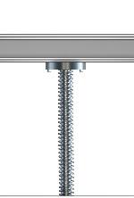
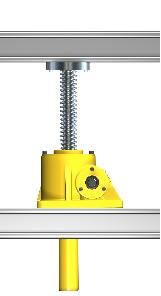
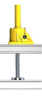
4 Versions Basic design GO, GU G configuration (basic design) has two versions: GO ( basic design, spindle above) and GU (basic design, spindle below). In both cases the spindle moves to transmit the linear lifting motion. The spindle is axially guided through the screw jack gear housing. Any tendency of the spindle to rotate must be resisted. Basic design Basic design GO Basic design GU Trapezoidal spindle Ball screw spindle Version GO Version GU.
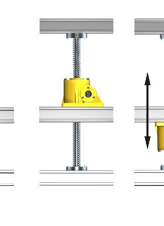
 and LU (running nut, spindle below).")

5 Versions Running nut design LO, LU L configuration (running nut) has two versions: LO ( running nut, spindle above) and LU (running nut, spindle below). The axial movement of the nut transmits the linear lifting motion due to spindle rotation. In this configuration the spindle is axially fixed in the gear housing. Running nut design Running nut design LO Running nut design LU Trapezoidal spindle Ball screw spindle Version LO Version LU 9.
6 Dimensions for SGT, SGT and SGT Versions GO, GU All versions are supplied with double worm shafts (version ) as standard. Optionally these can be supplied only on the left (version ) or the right (version ). Versions GO: Basic design, spindle above GU: Basic design, spindle below Basic design GO Ratio: Lubrication: grease N: normal, L: slow Material: see table page Accessories: see catalogue accessories for SGT screw jacks Questionnaire: see page Basic design GU Ø d Ø d Ø d Standard spindle end, see page Ø d Z = L + stroke L L stroke L 9 H stroke + L Ø d H stroke + L L 7 H H with single guidance collar Ø d stroke + L Z = stroke + L H L 9 stroke L L Ø d with two guidance collars Standard spindle end, see page Screw jack size SGT H H H H 9 H Ø H W Ø W H Ø d Screw jack sizes SGT and SGT H H Ø H H H H W H 9 H Ø W W W W W W W H H 7.
7 Dimensions [mm] Order code d d d H H H H H H H 7 H H 9 H H H H L L L L L L SGT SGT SGT ,, 7, Dimensions [mm] Order code L 7 L L 9 W W W W SGT SGT SGT k, k, k, 9 Only valid for versions in standard materials. General tolerances to DIN ISO 7 - medium, apply to machined surfaces. For all other dimensions casting tolerances apply.. 7
8 Dimensions for SGT to SGT, SGT 7 and SGT Versions GO, GU All versions are supplied with double worm shafts (version ) as standard. Optionally these can be supplied only on the left (version ) or the right (version ). Versions GO: Basic design, spindle above GU: Basic design, spindle below Basic design GO Basic design GU Ø d Ø d Ø d Standard spindle end, see page Ø d Z = L + stroke L L stroke L 9 H Z = L + stroke Ø d H stroke + L H Standard spindle end, see page Screw jack sizes SGT 7 and SGT H H H H Ø H H with single guidance collar stroke + L Z = L + stroke H L 9 stroke L L with two guidance collars Ø d Screw jack sizes SGT to SGT H H H Ø H H L 7 H H Ø d H 9 W Ø W H Ø d H H 9 Ø W W H 7 H W W W W W W H H 7.
9 Dimensions [mm] Order code d d d H H H H H H H 7 H H 9 H H H H L L L L L L SGT SGT SGT SGT SGT SGT SGT 7 SGT , , 7,,, 7, 97, Dimensions [mm] Order code L 7 L L 9 W W W W SGT SGT SGT SGT SGT SGT SGT 7 SGT 7 k 9, j k, k, k, k 7 7 k k Only valid for versions in standard materials. General tolerances to DIN ISO 7 - medium, apply to machined surfaces. For all other dimensions casting tolerances apply.. 9
10 Dimensions for SGT to SGT Standard spindle ends for versions GO, GU All versions are supplied with double worm shafts (version ) as standard. Optionally these can be supplied only on the left (version ) or the right (version ). Versions GO: Basic design, spindle above GU: Basic design, spindle below Ratio: Lubrication: grease N: normal, L: slow Material: see table page Accessories: see catalogue accessories for SGT screw jacks Questionnaire: see page Selection of the standard spindle ends: Ø d Ø d Ø d Ø d Ø d 7 H7 d GO d Ø d h7 L 7 L L L L L L 9 L L Z = L + stroke L GU Z=L + stroke L L Ordering example: Screw jack Size Basic design Spindle above Spindle end standard version Ratio N (normal) Worm shaft double ended (see page ) Mounting orientation (see page ) Worm shaft orientation (see page ) SGT GO - - N - - III/ - S Special version 7.
11 Dimensions [mm] Order code d d d d d d d 7 d L L L L L L L 7 L L 9 L L SGT SGT SGT SGT SGT SGT SGT SGT SGT SGT 7 SGT M Mx, Mx, Mx Mx Mx M7x Mx Mx Mx Mx Only valid for versions in standard materials. General tolerances to DIN ISO 7 - medium, apply to machined surfaces. For all other dimensions casting tolerances apply. Initial selection table Static lifting force ) Ratio Ratio N (normal) Lift per worm shaft rotation Overall efficiency Ratio Ratio L (slow) Lift per worm shaft rotation Overall efficiency Input power (S-%) max. spindle torque ) max permissible torque at worm shaft ) Spindle Spindle efficiency Lubricant quantity Mass without spindle Mass of spindle per m Order code SGT SGT SGT SGT SGT SGT SGT SGT SGT SGT 7 SGT F max. [kn] 7 i N,,,, [mm/ rev.],,7,,,,,,,7 tot. i [mm/ tot. P in. M sp. M in. Tr x P spindle [-] L rev.] [-] [kw] [Nm] [Nm] [mm] [-],,,,,,,9,,,,,,,,9,,,,,,,,,,,,,,,,9,,,,,,,,9, 7, 9,, x x x x7 x x 9x x x x x,,,,7,,,7,,,7,9 [kg],,,,,,7,,,,, m [kg], 7 9 m [kg/m],7,,, 7,9,,,7 7,7,7, ) The values for max. load apply only for initial jack selection. The actual permitted lifting force depends on the version of the jack and the operating conditions. ) max. torque the spindle can transmit ) important when screw jacks are in series e.g. where several units are constrained to operate together at same or differing speeds The values in the above table relate only to Albert-SGT-screw jacks in standard configuration (grease lubrication, spindle diameter, spindle lead ) and in standard materials. Units may be specified with oil lubrication. This provides higher efficiency and may allow selection of a smaller screw jack. The provision of comprehensive application data is essential to ensure the correct selection..
12 Dimensions for SGT, SGT and SGT Versions LO, LU All versions are supplied with double worm shafts (version ) as standard. Optionally these can be supplied only on the left (version ) or the right (version ). Versions LO: Running nut design, spindle above LU: Running nut design, spindle below Ratio: Lubrication: grease N: normal, L: slow Material: see table page Accessories: see catalogue accessories for SGT screw jacks Questionnaire: see page Running nut design LO Running nut design LU Standard spindle end, see page Ø d Z = L + stroke + L L L stroke L L H Ø d Ø d L= length of the running nut; see catalogue accessories for SGT screw jacks H L H Z = L + stroke + L L L Screw jack size SGT H H H 9 H H W Ø W Ø H L L stroke Ø d H H L H L= length of the running nut; see catalogue accessories for SGT screw jacks Standard spindle end, see page Screw jack sizes SGT and SGT H H H H W H 9 H Ø H H W W Ø W W W W W H H 7.
13 Order code Dimensions [mm] d d d H H H H H H H 7 H H 9 H H H H L L L L L L SGT SGT SGT ,, 7, Dimensions [mm] Order code W W W W SGT SGT SGT k k k,,, 9 Only valid for versions in standard materials. General tolerances to DIN ISO 7 - medium, apply to machined surfaces. For all other dimensions casting tolerances apply..
14 Dimensions for SGT to SGT, SGT 7 and SGT Versions LO, LU All versions are supplied with double worm shafts (version ) as standard. Optionally these can be supplied only on the left (version ) or the right (version ). Versions LO: Running nut design, spindle above LU: Running nut design, spindle below Running nut design LO Running nut design LU Standard spindle end, see page Ø d Z = L + stroke + L L L stroke L L Ø d H Ø d L= length of the running nut; see catalogue accessories for SGT screw jacks H L H Z = L + stroke + L L L L L stroke Ø d H H L H L= length of the running nut; see catalogue accessories for SGT screw jacks Standard spindle end, see page Screw jack sizes SGT to SGT Screw jack sizes SGT 7 and SGT H H H H H Ø H H H H H H 9 Ø H W Ø W H H H 9 Ø W W H 7 H W W W W W W H H 7.
15 Order code Dimensions [mm] d d d H H H H H H H 7 H H 9 H H H H L L L L L L SGT SGT SGT SGT SGT SGT SGT 7 SGT 9 9 -, 7 9-9, - 7, ,, , , Dimensions [mm] Order code W W W W SGT k 9, SGT j SGT k, SGT k, SGT k, SGT k 7 7 SGT 7 k SGT k Only valid for versions in standard materials. General tolerances to DIN ISO 7 - medium, apply to machined surfaces. For all other dimensions casting tolerances apply..
16 Dimensions for SGT to SGT Standard spindle ends for versions LO, LU All versions are supplied with double worm shafts (version ) as standard. Optionally these can be supplied only on the left (version ) or the right (version ). Versions LO: Running nut design, spindle above LU: Running nut design, spindle below Ratio: Lubrication: grease N: normal, L: slow Material: see table page Accessories: see catalogue accessories for SGT screw jacks Questionnaire: see page Selection of the standard spindle ends: d Ø d h7 LO L LU L L L L Z = L + stroke + L Z = L + stroke + L Ordering example: Screw jack Size Running nut design Spindle above Spindle end standard version Ratio N (normal) Worm shaft double ended (see page ) Mounting orientation (see page ) Worm shaft orientation (see page ) SGT LO - - N - - III/ - S Special version 7.
17 Dimensions [mm] Order code d d L L L L SGT SGT SGT SGT SGT SGT SGT SGT SGT SGT 7 SGT M Mx, Mx, Mx Mx Mx M7x Mx Mx Mx Mx Only valid for versions in standard materials. General tolerances to DIN ISO 7 - medium, apply to machined surfaces. For all other dimensions casting tolerances apply. Initial selection table Static lifting force ) Ratio Ratio N (normal) Lift per worm shaft rotation Overall efficiency Ratio Ratio L (slow) Lift per worm shaft rotation Overall efficiency Input power (S-%) max. spindle torque ) max permissible torque at worm shaft ) Spindle Spindle efficiency Lubricant quantity Mass without spindle Mass of spindle per m Order code SGT SGT SGT SGT SGT SGT SGT SGT SGT SGT 7 SGT F max. [kn] 7 i N,,,, [mm/ rev.],,7,,,,,,,7 tot. [-],,,,,,,9,,,, i L [mm/ rev.],,,,9,,,,,,, tot. [-],,,,,,,,,9,, P in. [kw],,,,,,9, 7, 9,,7 M sp. [Nm] M in. [Nm] Tr x P [mm] x x x x7 x x 9x x x x x spindle [-],,,,7,,,7,,,7,9 [kg],,,,,,7,,,,, m [kg], 7 9 m [kg/m],7,,, 7,9,,,7 7,7,7, ) The values for max. load apply only for initial jack selection. The actual permitted lifting force depends on the version of the jack and the operating conditions. ) max. torque the spindle can transmit ) important when screw jacks are in series e.g. where several units are constrained to operate together at same or differing speeds The values in the above table relate only to Albert-SGT-screw jacks in standard configuration (grease lubrication, spindle diameter, spindle lead ) and in standard materials. Units may be specified with oil lubrication. This provides higher efficiency and may allow selection of a smaller screw jack. The provision of comprehensive application data is essential to ensure the correct selection.. 7

18 Trapezoidal spindles for SGT to SGT Standard dimensions The trapezoidal spindles for Albert-screw jacks are accurately manufactured. The metric trapezoidal spindles are manufactured to DIN. Standard spindles are manufactured from heat treatable steel, drawn or peeled, h. The lead tolerance is ±, mm per mm length for a single start right hand thread. Multi-start and left handed threads are available. Please enquire. Thread quality: 7e L Ø d Ø d Ø d Tr H.
19 Size Tr x Dimensions [mm] d d min. d max. d H P,7,, Accuracy [ ã m/ mm] Straightness [mm/ mm] Lead angle at flank diameter Theoretical efficiency (for ã=,) Ý Mass of spindle per m Moment of intertia [-] [kg/m] [cm ] [cm ] [cm ] [kg m /m],,7,,,, x - Section modulus Polar moment of inertia Mass moment of inertia Tr x Tr x,7, 9,,,,,7,7, x -,7,,,,,7,9,9, x - Tr x 7,,7, 7, 9,7,,7,7,, x - Tr x,, 7,, 7,9,9,9,, x - Tr x,,,,,,9, 7, 9, x - Tr 9 x 9,, 7,,7,,97, 7,7, x - Tr x 9, 9,,,,7,9,,, x - Tr x,,,, 7,7,,,, x - Tr x,,,,7,7 7, 7,7,, x - Tr x 9, 9,7 Only valid for versions in standard materials. General tolerances to DIN ISO 7 - medium.,,9, 7,7,,, x -. 9
20 SGT Input power and torque Input power P in. [kw] Permitted input torque to worm shaft M in. [Nm] Valid for grease lubrication only! F eff. P in. Min. n in. Input speed n in. - [min ] Lifting velocity [mm/min] Vlift [mm/s],,,,,,,, 7,,,7,,,, 7, 7,9,, 9,,7,,7, 7, 7,, 7,,,, 9, 7, Ratio i N - L Effective load F [kn] eff.,, P in. M in. P in. M in. P in. M in. P in. M in. P in. M in. P in. M in. P in. M in.,,,,,,9,,,,,,,,,,,,,,7,,,,,,,,,,,,,,9,,,,,,,,,,,,,,7,,,,,,,,,,,,,,9,,,,,,,,,,,,,,7,,,,,,,,,,,,,,9,,,,,,,7,,,,,,,7,,,,,,,,,,,,,,9,,,,,,,,,,,,,,7,,,,,,,7,,,,,,,9,,,7,,,,,,,,,,,7,,,,,7,,9,,,,,,,9,7,,9,,, - -,,,,,,7,,,,,,,,,,,,,7,9,,,,,, - -,,,,,,7,,,7,,,,,,,,,,,9,,,, ,,,,,,7,7,,,,, - -,,,,,9,9,,,, ,,,,,,7,,,9,,, - -,,,,,,9,,,, ,,,,,7,7,9,,,,, - -,,,,,, ,,,,,,7,,,, ,,,,,, ,,,,,,7,,,, ,,,,,, ,,,,,9,7,,,, ,,,7,,, ,,,,,,7,,,, ,,,7,,, ,,,,,,7,,,, Please enquire for other operating conditions..
21 SGT Input power and torque Input power P in. [kw] Permitted input torque to worm shaft M in. [Nm] Valid for grease lubrication only! F eff. P in. Min. n in. Input speed Lifting velocity Ratio Effective load F [kn] eff.,, nin. [min-] [mm/min] Vlift [mm/s] i N - L P in. M in. P in. M in. P in. M in. P in. M in. P in. M in. P in. M in. P in. M in ,,,,7,,,, 7,,,,,,, 7, 7,9,, 9,,,,, 7,,,,,,,, 7,,,,,,,,,,,, 9,,,,,,,,,7,,,,,,,,,,,,,,,,,,, 9,,,,,,,,,7,,,,,,,,,,,,,,,,,,,9 9,,,,,,,,,7,,,,,9,,,,,,,,,,,,9,,9 9,,9,,,,,,,7,,,9,,,,,,,,,,,,,,,,9 9,,,,,,,,,7,,,,,,,,,,,,,,,,,,, 9, - -,,,,,,7,7,,,,,,,,,,,,,,9,,9, ,,,,,,7,9,,,,7,,,,,,,,,,,,, ,,,,,,7,,,,,,,,,,,,,,,,,, ,,,,,,7,,,,,,,,,,,,,,,9, ,,,,,7,7,,,7,,, - -,,,,,,,, ,,,,,7,7,,,,,, - -,,,,,,,, ,,,,,,7,,,,,9, - -,,,,,9,,9, ,,,,,9,7,,,, ,,,,,,,, ,,,,,,7,9,,9, ,,,,,,,, ,,,,,,7,,,, ,,,,,,,, ,,,,,,7,,,, Please enquire for other operating conditions..
22 SGT Input power and torque Input power P in. [kw] Permitted input torque to worm shaft M in. [Nm] Valid for grease lubrication only! F eff. P in. Min. n in. Input speed n in. - [min ] Lifting velocity [mm/min],,,,7,,,, 7,,,,,,, 7, 7,9,, 9,,,,, 7,,,,,,,, 7, Please enquire for other operating conditions. Vlift i P in. M in. P in. M in. P in. M in. P in. M in. P in. M in. P in. M in. P in. M in. [mm/s] N - L Ratio Effective load F [kn] eff.,,,,,,,,,, 9,9,, - -,,,,9,,,,,,,, - -,,,,,,,,, 9,9,, - -,,,,9,,,,,,,, - -,,,,,,,,, 9,9,, - -,,,,9,,,,,,,, - -,,,,,,,,, 9,9,, - -,,,,9,,,,,,,9, - -,,,,,,,,, 9,9,, - -,,,,9,,,,,9,,, - -,,,,,7,,,, 9, ,,,,9,,,,,,,, - -,,,,,,,, ,,,,9,,,9,,9,,9, - -,,,,,,,9, ,,,7,9,,,,,,,, - -,,,7,,,,, ,,,,9,,,,,9,,, - -,,,9,,, ,,,9,9,,,9,,,,, - -,,,,,, ,,,,9,,,,,, ,,,,,, ,,,,9,,,,,, ,,,,,, ,,,,9,9,,9,,, ,,,7,,, ,,,,9,,,, ,,,9,,9, ,,,,9,,,, ,,,,,, ,,,,9,,,,
23 SGT Input power and torque Input power P in. [kw] Permitted input torque to worm shaft M in. [Nm] Valid for grease lubrication only! F eff. P in. Min. n in. Input speed Lifting velocity Ratio Effective load F [kn] eff., n in. - [min ] [mm/min],97,,,7,9 9,,9,,9,,97, 7,,,7 7,,7,9, 9,7,, 7,7 7,9,7,,, 9,,,,9 7,,,,7 9, 9,7,9,,,,,,,7, 79,,, 7,,, 7 9, 7, 7, Please enquire for other operating conditions. Vlift i P in. M in. P in. M in. P in. M in. P in. M in. P in. M in. P in. M in. P in. M in. [mm/s] N - L,,,,9, 7,9,,,,,7, - -,,,,,,9, 7,9,,,, - -,,,,9, 7,9,7,,,,, - -,,,,,,9, 7,9,,,, - -,,,,9,7 7,9,,,,,, - -,,,,,,9, 7,9,,,, - -,,,,9, 7,9,,,7,,, - -,,,,,,9, 7,9,7,,9, - -,,,,9, 7,9,, ,,,,,,9, 7,9,9,,, - -,,,,9, 7,9,, ,,,,,,9, 7,9,,,, - -,,,,9, 7,9,, ,,,,,,9, 7,9,7,,99, - -,,,9,9, 7, ,,,,,9,9, 7,9,, ,7,,,9, 7, ,,,7,,,9, 7,9,99, ,9,,7,9,7 7, ,,,9,,7,9,7 7, ,,,,9, 7, ,,,,,,9, 7, ,,,, ,,,,,, ,,,9, ,,,,,9, ,7,,, ,,,7,,, ,9,,7, ,,,9,,7, ,,,, ,,,,,,
24 SGT Input power and torque Input power P in. [kw] Permitted input torque to worm shaft M in. [Nm] Valid for grease lubrication only! F eff. P in. Min. n in. Input speed Lifting velocity Ratio Effective load F [kn] eff. n in. - [min ] [mm/min] 7,,,,,,7 7,,,, 7,, 9,, 7,,,,, 7,,, 7, 9,,, 9,,, 7, 7, 7, Please enquire for other operating conditions. Vlift i P in. M in. P in. M in. P in. M in. P in. M in. P in. M in. P in. M in. P in. M in. [mm/s] N - L,,9,,9, 7,,7 7,, 9,, 9 - -,,,,,,,9,,,, - -,,9,,9, 7,,7 7,, 9,, 9 - -,,,,,,,,,,, - -,,9,,9, 7,,9 7,,99 9,, ,,,,,,,7,,,, - -,7,9,7,9,9 7,, 7, ,9,,,,7,,,,,,9 - -,,9,,9,99 7, ,,,,,,,,,, ,,9,,9,9 7, ,,,,,,,9,,, ,7,9,, ,,,7,,,,, ,7,9,7, ,,,,,7, ,,9,, ,,,,,, ,,9,, ,7,,,,, ,,9,, ,,,,,, ,7, ,9,,, ,, ,7,,, ,, ,,,, ,7, ,,,7, ,7, ,9,,,
25 SGT Input power and torque Input power P in. [kw] Permitted input torque to worm shaft M in. [Nm] Valid for grease lubrication only! F eff. P in. Min. n in. Input speed Lifting velocity Ratio Effective load F [kn] eff. 7 n in. - [min ] [mm/min] 7,,,,,,7 7,,,, 7,, 9,, 7,,,,, 7,,, 7, 9,,, 9,,, 7, 7, 7, Please enquire for other operating conditions. Vlift i P in. M in. P in. M in. P in. M in. P in. M in. P in. M in. P in. M in. P in. M in. [mm/s] N - L,,,,,7 9,,,7, 9,,,,,,,7,, 7,, 97,,,,,,,9 9,,,, 9,,,,,,,7,,77 7,, 97,,,,,,,9 9,,, ,,,,,9,7,, 7,, 97,,,9,,9,, 9, ,,,9,,,7,9, 7,, 97, - -,,,, ,,,,,9,7, ,7,,, ,,,,,9,7, ,9, ,9,,9,,7, ,, ,,,,,, ,, ,7,,,,, ,, ,,,7, ,, ,,,9, ,7, ,9, ,7, ,, ,9,
26 SGT Input power and torque Input power P in. [kw] Permitted input torque to worm shaft M in. [Nm] Valid for grease lubrication only! F eff. P in. Min. n in. Input speed Lifting velocity Ratio Effective load F [kn] eff. 7 n in. - [min ] [mm/min] [mm/s] 7,,,,,,, 7,,,, 7,, 9,, 7 7,,,, 9, 7, 9,, i N - L,,,,,,,,,,, P in. M in. P in. M in. P in. M in. P in. M in. P in. M in. P in. M in. P in. M in.,,9,9 9,,,7,,,,,, - -,9,,,,7 7,, 9,,,9,7, - -,,9, 9,,,7,7,,,,, - -,7,,,,7 7,,97 9,,9,9,9, - -,,9,9 9,,,7,,,, ,7,,,,9 7,,9 9,,9,9,9, - -,9,9,9 9,,9, ,,,,, 7,,9 9,,,9,7, - -,,9,9 9, ,9,,,,9 7,, 9,,77, ,9,9,9 9, ,,,,,7 7,, 9, ,9, ,,,,,7 7, ,, ,,,9, ,9,,7, ,, ,7, Please enquire for other operating conditions..
27 SGT Input power and torque Input power P in. [kw] Permitted input torque to worm shaft M in. [Nm] Valid for grease lubrication only! F eff. P in. Min. n in. Input speed Lifting velocity Ratio Effective load F [kn] eff. n in. - [min ] [mm/min] [mm/s] i N - L 7,,,,,,9, 9,,7, 9 - -,,9,,7 7,,7,9 77, - -,,,9,,7, 9,7, ,,7,,7 7,,9, 77, - -,,,7,,7, 9, ,,7,,9 7,,97, ,,,,, ,,,, 7,,, ,,,7,, ,,9,,97 7, ,,,, ,,,,7 7, ,,,, ,,,, ,,,, ,,,, ,,,, ,,97,, ,, ,,, ,, ,,7, Please enquire for other operating conditions. P in. M in. P in. M in. P in. M in. P in. M in. P in. M in. P in. M in. P in. M in.. 7
28 SGT Input power and torque Input power P in. [kw] Permitted input torque to worm shaft M in. [Nm] Valid for grease lubrication only! F eff. P in. Min. n in. Input speed Lifting velocity Ratio Effective load F [kn] eff. n in. - [min ] [mm/min] [mm/s] 7,,,,,,, 7,,,, 7,, 9,, i N - L,,,,,,, P in. M in. P in. M in. P in. M in. P in. M in. P in. M in. P in. M in. P in. M in., 9,,,9,7,, 9, 77,, 7, - -,,,9,,9 7,,,9,,,7 - -,7 9,,,9,,,7 9, 77,,7 7, - -,9,,9,, 7,,,7,,7,7 - -, 9,,,9,7, ,,,79,,7 7,,,, 7,,7 - -, 9, 7,, ,7,,7,, 7,, ,7 9, ,7,,, 7, 7, ,,,9, ,, Please enquire for other operating conditions..
29 SGT 7 Input power and torque Input power P in. [kw] Permitted input torque to worm shaft M in. [Nm] Valid for grease lubrication only! F eff. P in. Min. n in. Input speed Lifting velocity Ratio Effective load F [kn] eff. 7 n in. - [min ] [mm/min] [mm/s] 7,,,,,,7 7,,,, 7,,7 9,, 7,,,,7, 7,,, i N - L,,,,,,,,,,, P in. M in. P in. M in. P in. M in. P in. M in. P in. M in. P in. M in. P in. M in.,9 7,,,,7,,,,,, 9,7, 99,, 99,, 9,, 97,9, 97,,,,9 7, 7,,,,, 7,,,9, , 99,, 99,, 9,, 97,9, 97,,, 7, 7, 7, 7,, , 99,, 99,, 9,, 97, , 7,,7, , 99,, 99, 9, 9, , 7, , 99,, 99, ,9 7, , 99, , 99, , 99, , 99, , 99, Please enquire for other operating conditions.. 9
30 SGT Input power and torque Input power P in. [kw] Permitted input torque to worm shaft M in. [Nm] Valid for grease lubrication only! F eff. P in. Min. n in. Input speed Lifting velocity Ratio Effective load F [kn] eff. n in. - [min ] [mm/min] [mm/s],, 7,,,,,,9,,,,9,,7,,,,,7,,9 77,,,,, 7 9,,9,,, 7,, 7 7,, 9, i N - L P in. M in. P in. M in. P in. M in. P in. M in. P in. M in. P in. M in. P in. M in.,,,7 7,,, - -,7, 7,99 79,,, 7 - -,, 7, 7,, ,,7 7,97 79,, 9, 7 - -,, ,7, 7 7,9 79, ,9, ,, 7, , , 9, , ,, , , , , , , Please enquire for other operating conditions..

 z III (wall mounted) -x y x -z II (inverted) Ordering")
 Worm shaft double ended Mounting orientation Worm shaft orientation SGT GO - - N - - III/")
31 Installation of SGT screw jacks Worm shaft - mounting orientation - worm shaft orientation Recommended guidelines for screw jack arrrangements: -Spindle in tension -Housing in compression -Fixing screws unloaded Worm shaft: = left = double ended = right Mounting orientation: I (upright) Worm shaft orientation: (for wall mounting) z III (wall mounted) -x y x -z II (inverted) Ordering example: Screw jack Size Basic design (see page / ) Spindle above Spindle end standard version Ratio N (normal) Worm shaft double ended Mounting orientation Worm shaft orientation SGT GO - - N - - III/ - S Special version.
32 Suggested drive arrangements - mechanically synchronised Examples When designing screw jack arrangements, the operating requirements, the load to be moved and the stroke must be known. Additional loads which are not axially transmitted must be taken into account. Once the number of jacks and their orientation is established the load must be calculated for individual jacks. Next the drive train for the screw jacks is established. Example X Please observe the following guidelines: all screw jacks in the arrangement examples have the same sense of rotation the number of connecting links is as small as possible the motor should be located close to the most heavily loaded screw jacks Example 7 X Arrangement examples X and Y are centre distances Example Example X Example Example 9 X X Example X Y Example Example Example X Y Y X X.
33 Suggested drive arrangements - mechanically synchronised Example Example X X Y Example X Example Example X X Y Y Example X Example X Example 7 Y X.

34 Installation examples SGT - SGT F F F F F F F F F F F 9.
35 Dimensioning of screw jack systems Selection path Establish length of spindle [mm], lifting speed V [m/min] and effective load F lift eff. [kn] for each screw jack The calculation of duty rating ED [%/h] (see page ) is unneccessary when relatively little use is made of the system. E.g. callibration or similar activities. Initial selection based on effective load F [kn], lifting speed V [m/min] and duty ED [%/h]. (see pages / 7/ ) eff. lift No Is the spindle compressively loaded? Yes Checking the tendency to buckling F [kn]. (see pages / 7) crit. GO/ GU Version LO / LU or version GO / GU? LO/ LU Checking the critical spindle speed n [/min]. (see page ) crit. Calculating the torque in the lifting spindle M [Nm]. (see page 9) sp. Should a ball screw be considered? Calculation of the required input torque M [Nm] per screw jack. (see page 9) in. Calculation of the total required input torque M [Nm] for the screw jack system. (see page ) tot. Calculation of the required input speed n [/min]. (see page 7) in. Calculation of the required input power P [kw]. (see page 7) in. Calculation of the actual lifting speed V [m/min] (see page 7) and selection of the motor. (see page 9) lift act. 7.
![Definition of the applied loads, torques and speeds F [kn] effective lifting load of the screw jack eff.](/docs-images/78/77822030/images/36-0.jpg "F [kn] maximum radial load r max. M [Nm] input torque in. M [Nm] maximum input torque max.")
![M [Nm] torque in the lifting spindle sp. n [/min] input speed in.](/docs-images/78/77822030/images/36-1.jpg "n [/min] spindle speed (only running nut design) V [m/min] lifting speed lift F eff. M sp.")
36 Definition of the applied loads, torques and speeds F [kn] effective lifting load of the screw jack eff. F [kn] maximum radial load r max. M [Nm] input torque in. M [Nm] maximum input torque max. M [Nm] torque in the lifting spindle sp. n [/min] input speed in. n [/min] spindle speed (only running nut design) V [m/min] lifting speed lift F eff. M sp. F eff. M sp. n F r max M / M / n in. m ax in. F r max M / M / n in. m ax in. 9.
37 Calculations Input speed n in. [/min] Required input speed n in. [/min] to achieve a partciular lifting speed [m/min] is calculated as follows: [m/min] n in. [/min] = i [-] P [mm] [m/min] lifting speed at the spindle P [mm] spindle pitch i [-] screw jack ratio Input power P [kw] in. per screw jack Required input power calculated as follows: P [kw] = in. Input power P [kw] machine for total system Overall required input power P machine [kw] for the complete system (screw jack, connecting shafts, bevel gear units) is calculated as follows: P [kw] = machine P [kw] in. F eff. [kn] [m/min] tot. F eff. tot. [kn] [m/min] tot. machine for a particular screw jack is F eff. [kn] effective lifting load of the screw jack [m/min] lifting speed at the spindle tot. [-] total working efficiency (see table) Order code N - i - L η tot. SGT SGT SGT SGT SGT SGT SGT SGT SGT SGT SGT SGT SGT SGT SGT SGT SGT SGT SGT 7 SGT 7 SGT SGT,,,,,,,,,,,,,,,,,9,,,,,9,,,, F eff. tot. [kn] effective load to be lifted for the system [m/min] lifting speed at the spindle tot. [-] total working efficiency (see table) machine [-] efficiency of the system (see page ) Actual lifting speed V lift act. [m/min] In most cases the required input speed n in. [/min] differs from the motor speed. The actual lifting speed act. [m/min], which will be achieved based on motor speed n motor [/min] is calculated as follows: V [m/min] = lift act. n [/min] P [mm] motor i [-] act. [m/min] actual lifting speed n motor [/min] motor speed P [mm] spindle pitch i [-] screw jack ratio. 7
38 Calculations Maximum radial load worm shaft F [N] r max. at the Maximum input torque M [Nm] max. Maximum radial load at the worm shaft F r max. [N] The worm shaft can experience radial loads due to gears, sprockets or belt pulleys. To avoid exceeding the max radial load F r max. [N] the minimum shaft diameter D min. must be calculated. Order code SGT SGT F r max. [N] M max. [Nm],9 9 P in. [kw] M max. [Nm] D min. [m] = = F r max. [N] n in. [/min] F r max. [N] SGT SGT SGT 7, D [m] smallest diameter min. P [kw] input power in. F [N] maximum radial load (see table) r max. n in. [/min] input speed at the worm shaft M max. [Nm] maximum input torque (see table) SGT SGT SGT SGT 9 79 SGT l SGT l/ Ø D F r max. Duty ED [%/h] The duty ED [%/h] is derived from the time in operation (lifting and lowering) and the inactive time between successive operations. Example: Lifting Lowering Inactive s s s s s s s s s Total cycle = s ED per cycle in % = % Cycles per operating day= ED [%/h] = Stroke [m] LS V [m/min] lift Stroke [m] working stroke of the screw jack [m/min] lifting speed LS [-] number of loaded operations.
39 Calculations Input torque M [Nm] in. P in. [kw] input power (see page 7) n in. [/min] input speed at the worm shaft at the worm shaft The input torque M in. [Nm] at the worm shaft is calculated as follows: M [Nm] = in. P [kw] 9 in. n [/min] in. Selection of the motor The required motor can be selected from the power P in. [kw] and the input speed n in. [/min]. Notes about motor selection: The motor selected should be able to overcome the breakaway torque of the system which can be considerably higher than the calculated input torque. This relates particularly to systems where there is poor efficiency and long idle periods. Following selection of the drive motor it should be checked whether the transmission elements and the screw jacks may be overloaded by the selected motor. For maximum input torque M [Nm] see the adjacent table. max. When using some trapezoidal spindles a brake motor should be selected since self locking cannot be guaranteed. In conditions of heavy vibration the self locking capability of some screw jacks can no longer be guaranteed. In such cases, or where it is possible that such vibration may occur, a brake motor must be specified. To minimise the possibility of damage to the screw jack system, end of travel limit switches should be fitted. E.g. electro-mechanical devices or inductive proximity devices. Torque M [Nm] sp. in the lifting spindle The torque in the lifting spindle M sp. [Nm] is that torque that the lifting spindle exerts at the spindle end in basic design. In the running nut design M sp. [Nm] is that torque which the running nut exerts on the spindle due to the load. M [Nm] = sp. F [kn] P [mm] lift dyn. spindle Order code η ) spindle SGT SGT SGT SGT SGT SGT,,,,7,, F lift dyn. [kn] dynamic lifting load on the screw jack P [mm] spindle pitch (see page, 7) spindle [-] efficiency of the spindle (see table) SGT SGT SGT SGT 7,7,,,7 SGT,9 ) only applies for trapezoidal spindles; for ball screw spindles η spindle=,9. 9
40 Calculations Total input torque M [Nm] tot. The total torque M tot. [Nm] required for the system comprises the llifting load torque, plus losses due to flexible couplings, cardans, support bearings and bevel gearboxes. The following example shows the derivation of the total torque M tot. [Nm]. M ( in. M in. η cardan shaft η cardan shaft ) M tot. = + η K M tot. [Nm] total input torque M in. [Nm] input torque for screw jack M in. [Nm] input torque for screw jack η cardan shaft [-] Efficiency of cardan shaft with support bearing (dependent on the length and the number of support bearings ca..7 to.9) η k [-] efficiency of bevel gearbox (ca..9) Note: If a bevel gearbox with a ratio i k [-] of greater than is used then the torque and input speed must be modified accordingly. Important: The breakaway torque of the system can be considerably higher than the calculated input torque. This applies particularly to systems with poor efficiency and long idle periods. screw jack coupling phase motor support bearing cardan shaft screw jack bevel gearbox cardan shaft support bearing.
41 Calculations Spindle efficiency [-] spindle The spindle efficiency [-] is calculated as follows: spindle spindle [-] = tan tan( + ) [-] lead angle at flank diameter... ( ) ( ) P = arctan...single start spindle d P h = arctan...multistart spindle d [-] wear angle of the spindle (based on,9 for well greased spindle) P [mm] spindle lead - multistart h (example: Tr x P7; P h=) P [mm] spindle lead - single start (example: Tr x7; P=7) pitch of spindle - multistart (example: Tr x P7; P=7) d [mm] flank diameter of spindle d = d-, P d [mm] external diameter of spindle Surface stress in thread p [N/mm²] Calculation of surface stress p [N/mm²] in thread: p [N/mm²] = F [N] P [mm] lift dyn. l [mm] d [mm] H [mm] F lift dyn. [N] dynamic lifting load on the screw jack P [mm] lead for single start spindle; pitch for multistart spindle l [mm] length of nut thread d [mm] flank diameter of spindle H [mm] flank engagement Life calculation The life L h [h] for the ball screw spindle or bearing is calculated as follows: L [h] = h C dyn. [kn] F lift dyn. [kn] C dyn. [kn] dynamic load rating of ball screw spindle/ ball bearing F lift dyn. [kn] dynamic lifting load on the spindle when in motion (axial) n [m/mm] ball screw spindle/ ball bearing speed n = L [h] h ( ) n [m/min] n [/min] input speed at the worm shaft in. n in. [/min] i [-] ball screw spindle / ball bearing.
42 Calculations Critical spindle speed n crit. (only running nut design) Rotating spindles are subject to vibration due to resonance. All rotating spindles should be checked for speed n [/min] vs permitted speed. Method:. Determination of the spindle speed n [/min] n [/min] = V [m/min] lift P [mm] Tr x Tr x Tr x Tr x7. Obtain the critical spindle speed n crit. [/min] from the graph. The spindle size and the length L n [mm] is required.. Determination of the permitted spindle speed n perm. [/min]: n [/min] =, n [/min] f [-] perm. crit. n n crit. [/min]. The permitted spindlle speed n perm. [/min] must be greater than the actual spindle speed n [/min]. n > n perm. f =, n L n [mm] L n f = n 7 9 Tr x Tr x Tr 9x Tr x Tr x Tr x Tr x L n f =, n L n n crit. [/min] 7 9 f =, n L n L n [mm].
43 Calculations Permissible side loading F [kn] S on the spindle due to compressive loads The permissible side loading F S [kn], resulting from compressive axial loading F a [kn], can be obtained from the graph below: Important: The permitted side load F s acting via the spindle to the running nut leads to increased edge pressure in the actuating spindle. Wear is increased and life reduced. If in doubt consult our engineers! Buckling safety factor: Comparative stress: Tetmajer:... Euler: é Vmax. < é Vperm. é é é ê = + ² + ² V ( B D ) t F a Spindle Tr x a F S 9 7 a = a = a = 7 a = a = a = Side load F S [N] For GO-GU with second guidance collar For LO-LU only for static loading Axial load Fa [kn] Spindle Tr x Spindle Tr x,,9,,7 a = a = 7 a = a = a = a =,,,, a = a = 7 a = a = a = a = Side load F S [kn],,,, Side load F S [kn],,,,,,,, Axial load Fa [kn] Axial load Fa [kn].
44 Calculations Permissible side loading F [kn] S on the spindle due to compressive loads Buckling safety factor: Tetmajer:... Euler: Comparative stress: é Vmax. < é Vperm. é é é ê = + ² + ² V ( B D ) t Important: The permitted side load F s acting via the spindle to the running nut leads to increased edge pressure in the actuating spindle. Wear is increased and life reduced. If in doubt consult our engineers! Spindle Tr x7 Spindle Tr x,,7,, a = 7 a = a = a = a = a =, 7,,, a = a = a = a = a = Side load F S [kn],,, Side load F S [kn],,,,9,,,,, Axial load Fa [kn] 9 Axial load Fa [kn] Spindle Tr x Spindle Tr 9x 9 7 a = a = a = a = a = a =,,,, a = a = a = a = a = 7 Side load F S [kn] Side load F S [kn] 9, 7,,,,, Axial load Fa [kn] Axial load Fa [kn].
45 Calculations Permissible side loading F [kn] S on the spindle due to compressive loads Buckling safety factor: Tetmajer:... Euler: Comparative stress: é Vmax. < é Vperm. é é é ê = + ² + ² V ( B D ) t Important: The permitted side load F s acting via the spindle to the running nut leads to increased edge pressure in the actuating spindle. Wear is increased and life reduced. If in doubt consult our engineers! Spindle Tr x a = a = a = a = a = 7 7 Spindle Tr x 7 a = a = a = a = a = a = a = Side load F S [kn] Side load F S [kn] Axial load Fa [kn] Axial load Fa [kn] Spindle Tr x 7 a = a = a = a = a = a = a = Spindle Tr x a = a = a = a = 7 a = a = a = Side load F S [kn] Side load F S [kn] Axial load Fa [kn] Axial load Fa [kn].
46 SGT l l l SGT screw jack Calculations Critical buckling loads F [kn] crit. on the spindle Under compressive loading slim spindles tend to buckle. For this reason all compressively loaded spindles must be checked for permitted axial loading. Euler case Euler case Euler case Safety margin Tetmajer:... increasing Euler : Safety margin Tetmajer:... increasing Euler : SG T S GT SGT F crit. [kn] F crit. [kn] S GT SGT SGT SGT SGT S GT SGT SG T Spindle length l [mm] Spindle length l [mm].
47 Calculations Critical buckling loads F [kn] crit. on the spindle Safety margin Tetmajer:... increasing Euler : Safety margin Tetmajer:... increasing Euler : SGT S GT SGT F crit. [kn] S G T SGT F crit. [kn] SGT SGT S GT SGT Spindle length l [mm] Spindle length l [mm] Safety margin Tetmajer:... increasing Euler : Safety margin Tetmajer:... increasing Euler : S GT SGT SGT 9 SGT SG T S G T SG T 7 7 SGT 7 SGT 7 F crit. [kn] F crit. [kn] S GT 7 SGT SG T Spindle length l [mm] Spindle length l [mm]. 7
48 Gear housing material Selection table Gear housings for ALBERT-screw jacks are manufactured from the best possible materials. Alongside the standard materials there are a number of other options. If the adjacent table does not contain the material you require, please ask. Screw jack size Al GG Inox / VA St GS GGG ) ) ) ) ) ) SGT SGT SGT SGT SGT SGT SGT SGT SGT SGT 7 SGT ) Aluminium ) Grey cast iron ) Corrosion resistant version ) St ) Cast steel ) SG iron - standard - option - not possible.
49 Installation and maintenance Assembly Maintenance of SGT to SGT For ease of installation, ensure machined mounting faces are provided with through bored holes. Important: It should be ensured, wherever possible, that spindle nut fixing screws are compressively loaded. F The spindle should be regularly cleaned and relubricated. Every operating hours or every months the grease in the gear housing should be replaced.. Dismount the screw jack and clean.. Disassemble the spindle and spindle protection tube. (only for translating spindle). Remove locking screw for gear housing cover.. Wash out the gear housing and components with a suitable wash medium.. Refill with grease according to the table below. F F When carrying out maintenance, check wear on the spindle nut. Measure the axial play between the spindle and the nut. The maximum values are shown in the table. If the maximum values have been exceeded the gear unit must be overhauled. Ideally return to Albert for restoration to functional condition. After checking the wear the unit should be re-assembled by a fitter. Check carefully that rotation is smooth and light and free from axial play. This is a short version of recommended maintenance. With each order acknowledgement the current version of the complete Installation and maintenance instructions will have been provided. Order code Grease quanitity [kg] max. axial play [mm] SGT,, SGT,, SGT,, The screw jack should be aligned using a spirit level. Parallel alignment between the lifting system and the guide mechanism must be carefully checked. SGT SGT,,,7, Screw jacks systems should be checked for twisting and for tight spots. To check this the lifting system should be actuated by hand over the entire stroke. The force required should be light and even. SGT SGT SGT,7,,,,, The direction of rotation of the screw jacks should be carefully checked. SGT SGT 7,,,, Before test running the spindle(s) must be cleaned and if possible sprayed with an aerosol grease lubricant over the entire stroke length. SGT,, When test running:. Check the function and position of any limit switches.. Test the lifting system initially without load if possible.. Increase the load incrementally, checking for any hot spots and for gearbox temperature rise.. Check the tightness of all screwed connections. Important: Do not exceed the permitted loads, duty and input speeds. Failure to observe this will invalidate your guarantee. Recommended greases: The screw jack is factory filled with Castrol Spheerol EPL which complies with DIN : KP K- 7. 9
50 Questionnaire for quotation purposes Company:... Department:... Contact:... Date:... Tel.:... Fax.:... Address:... Project:... Loads: No. of screw jacks in system:... Axial load Total system Per spindle dynamic [kn] static [kn] dynamic [kn] static [kn] Compressive load Tensile load Type of loading: steady oscillating shock increasing vibrating Stroke: Stroke length [mm]... Lifting speed [m/min]:... Application information: Usage per day in hours Working cycle: actual in... sec. min. Example: Usage per day in hours Working cycle: actual in... sec. X min. Lifting Lifting Lowering Lowering Idle Idle Total cycle time Total cycle time ED per cycle in % ED per cycle in % Cycles per working day Cycles per working day Operational conditions: Environmental temperature from C... to C... dry humid dusty (define material):... other effects:... Details about the planned location and attitude Attitude: (upright) (inverted) (wall mounted) Spindle guidance: without guidance with guidance Requirements: Number of sets:... Quantity per year:... Required delivery:... Accessories: Please indicate the accessories required on the next page! For the best design please provide a drawing! 7.
 Dimension Z ) Stroke Spiral protective sleeve Motor adaptor")
 Dimension Z = underside of gear housing to end of standard spindle, and ) Dimension L + stroke = underside of gear housing to centre of clevis bore")
51 Questionnaire Accessories for basic design GO (translating spindle) Tensile load, dynamic kn Tensile load, static kn Compressive load, dynamic kn Standard spindle end Standard spindle end Standard spindle end Standard spindle end Compressive load, static kn Standard spindle end Folding bellows Dimension L + stroke ) Dimension Z ) Stroke Spiral protective sleeve Motor adaptor Flexible coupling Motor Screw jack Pivot mounting Protective tube Rotation prevention Pivot fork Pivot base unit Travel limiter, linear cam Limit switch with angled lever Clevis attachment Square rotation preventer Hand crank ) Dimension Z = underside of gear housing to end of standard spindle, and ) Dimension L + stroke = underside of gear housing to centre of clevis bore standard spindle end 9.

 Dimension Z = underside of gear housing to end of standard spindle, and ) Dimension L + stroke = underside of gear housing to centre of clevis bore standard spindle")
52 Questionnaire Accessories for basic design GU (translating spindle) Tensile load, dynamic kn Tensile load, static Compressive load, dynamic Compressive load, static kn kn kn Limit switch with angled lever Clevis attachment Square rotation preventer Protective tube Rotation prevention Travel limiter, linear cam Motor Flexible coupling Motor adaptor Screw jack Pivot mounting Dimension L + stroke ) Dimension Z ) Stroke Pivot fork Pivot base unit Spiral protective sleeve Folding bellows Hand crank Standard spindle end Standard spindle end Standard spindle end Standard spindle end Standard spindle end ) Dimension Z = underside of gear housing to end of standard spindle, and ) Dimension L + stroke = underside of gear housing to centre of clevis bore standard spindle end 9.
 Dimension Z ) Stroke Folding bellows Spiral protective sleeve Motor adaptor Flexible coupling Motor Screw jack Pivot mounting Pivot fork Pivot")
53 Questionnaire Accessories for running nut design LO (rotating spindle) Tensile load, dynamic kn Tensile load, static kn Compressive load, dynamic Compressive load, static kn kn Standard spindle end Standard spindle end Standard spindle end Flanged nut ) Dimension Z ) Stroke Folding bellows Spiral protective sleeve Motor adaptor Flexible coupling Motor Screw jack Pivot mounting Pivot fork Pivot base unit Hand crank ) Dimension Z = underside of gear housing to end of spindle ) For further versions see catalogue accessories for SGT screw jacks. 9.
 Stroke Hand crank Folding bellows Spiral protective sleeve Flanged nut ) Standard spindle end Standard spindle end")
54 Questionnaire Accessories for running nut design LU (rotating spindle) Tensile load, dynamic kn Tensile load, static kn Compressive load, dynamic kn Compressive load, static kn Motor adaptor Flexible coupling Motor Screw jack Pivot mounting Pivot fork Pivot base unit Dimension Z ) Stroke Hand crank Folding bellows Spiral protective sleeve Flanged nut ) Standard spindle end Standard spindle end Standard spindle end ) Dimension Z = underside of gear housing to end of spindle ) For further versions see catalogue accessories for SGT screw jacks. 9.
, completely rust proof, yellow paint.")

7-9- 7.")
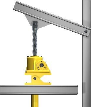
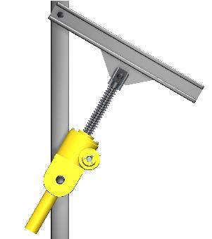
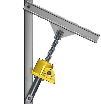
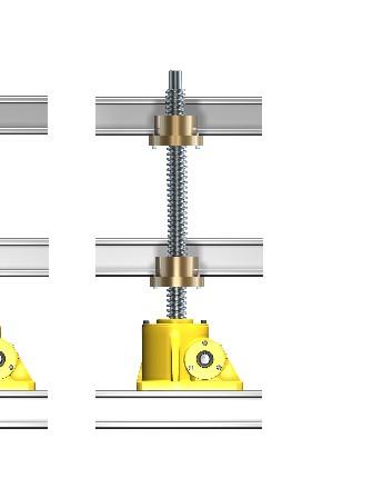
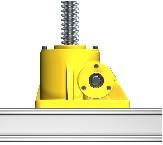
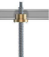
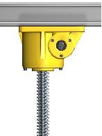
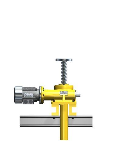
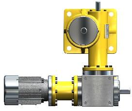
55 Application examples Screw jacks system for paper industry, SGT GO configuration (Hermes PM), completely rust proof, yellow paint. Welding fixture with screw jack system SGT, integrated safety nut for both tensile and compressive loading. Screw jack SGT, special version, with integral guidance tube. Stroke mm. We reserve the right to make technical Maschinenfabrik ALBERT GmbH Phone: +/ () changes. For current information go to Technologiepark Fax: +/ () or your local sales office. A- Gampern
DSH screw jack. Product description. DSH screw jack
 Product description DSH screw jack Conventional screw jack applications consist of one or more screw jacks. Usually they are driven by one electric motor and typically connected via drive shafts or couplings
Accessories for screw jacks type SGT
 Product description Accessories for Albert SGT screw jacks Both trapezoidal and ball screw version The comprehensive range of Albert accessories for screw jacks provides the designer with the means to
DRIVE-TECHNOLOGY INKOMA - GROUP. Accessories for screw jacks type SGT. Maschinenfabrik ALBERT GmbH Technologiepark 2 A Gampern - Austria
 DRIVETECHNOLOGY ALBERTINKOMA GROUP Accessories for screw jacks type SGT Maschinenfabrik ALBERT GmbH Technologiepark 2 A 81 Gampern Austria phone: +3/(0)76823 fax: +3/(0)7682399 email: office@albert.at
PK couplings. Product description. PK couplings
 Product description The INKOMA-PK coupling is machine component designed to transmit torque between axially parallel, radially offset shafts. The coupling permits both static and dynamic stepless adjustment
Product description. PK couplings
 Product description The INKOMA-PK coupling is machine component designed to transmit torque between axially parallel, radially offset shafts. The coupling permits both static and dynamic stepless adjustment
Series BD Screw Jacks
 www.radicon.com Series BD Screw Jacks Technical Up to - 100Te / 5m/min Screw Jacks CBD-1.00GBD0111 SERIES BD PRODUCTS IN THE RANGE Serving an entire spectrum of mechanical drive applications from food,
Linear Drive with Ball Screw Drive Series OSP-E..SB
 Linear Drive with Ball Screw Drive Series OSP-E..SB Contents Description Data Sheet No. Page Overview 1.30.001E 47-50 Technical Data 1.30.002E-1 to 5 51-55 Dimensions 1.30.002E-6, -7 56-57 Order instructions
C-SERIES S-SERIES. Metric Machine Screw Jacks EMA LINEAR ACTUATORS
 C-SERIES S-SERIES Metric Machine Screw Jacks EMA LINEAR ACTUATORS Power Jacks has a proud engineering heritage dating from the earliest years of the 20th Century. A heritage that is about excellence: about
Linear Actuator with Ball Screw Series OSP-E..S. Contents Description Overview Technical Data Dimensions 89
 Linear Actuator with Ball Screw Series OSP-E..S Contents Description Page Overview 79-82 Technical Data 83-88 Dimensions 89 79 The System Concept ELECTRIC LINEAR ACTUATOR FOR HIGH ACCURACY APPLICATIONS
Roller chain idler sprocket units Idler pulley units
 Roller chain idler sprocket units Idler pulley units Roller chain idler sprocket units, idler pulley units Page Product overview Roller chain idler sprocket units, idler pulley units... 334 Design and
Screw Jacks. Lifting >> Tilting >> Lowering >> Feeding sm. MARYLANDMETRICS phones: (800) (410) faxes: (800) (410)
 (410) faxes: (800) (410)") Cubic Screw Jack Family MULI, JUMBO MULI, JUMBO Lifting >> Tilting >> Lowering >> Feeding sm Cubic Screw Jacks RHINO MARYLAND METRICS offers: Screw Jacks Superior performance. Superior design. MARYLANDMETRICS
Cubic Screw Jack Family MULI, JUMBO MULI, JUMBO Lifting >> Tilting >> Lowering >> Feeding sm Cubic Screw Jacks RHINO MARYLAND METRICS offers: Screw Jacks Superior performance. Superior design. MARYLANDMETRICS
KTR Torque Limiters Overload Protection Systems
 KT Torque Limiters Overload Protection Systems UFLEX - Friction Disk - Zero Backlash Ball Detent KT SI - Ball/oller Bearing Style KT SI Compact - Zero Backlash Ball Detent Catalog Contents (Metric) Page
Contents. Page. 1. Product description. 2. The AXC line of linear axes. 3. AXLT line of linear tables. AXC and AXS product overview...
 SNR Industry Contents Page 3 1. Product description AXC and AXS product overview... 6-8 Dynamic load ratings of the linear motion systems... 9 Compact modules... 10-11 Linear tables... 12 Telescopic axes...
Linear Actuator with Ball Screw Series OSP-E..S. Contents Description Overview Technical Data Dimensions 79
 Linear Actuator with Ball Screw Series OSP-E..S Contents Description Page Overview 71-74 Technical Data 75-78 Dimensions 79 71 The System Concept ELECTRIC LINEAR ACTUATOR FOR HIGH ACCURACY APPLICATIONS
Servomechkaramoottorit
 Solutions for power transmission Servomechkaramoottorit www.konaflex.fi INDEX 1 Servomech 1. THE PRODUCT 1.1 SERVOMECH Linear Actuators......................... Page 2 1.2 SERVOMECH Linear Actuators range............................
Selection, Calculation, Checklists
 Selection of Screw Jack System and Arrangement 4.1 Consideration of application requirements 4.2 Parameter see checklist 1 to 6 S version standing spindle Preselection of screw jack size see diagram on
Linear Actuator with Toothed Belt Series OSP-E..B
 Linear Actuator with Toothed Belt Series OSP-E..B Contents Description Data Sheet No. Page Overview 1.20.001E 21-24 Technical Data 1.20.002E-1 to 5 25-29 Dimensions 1.20.002E-6 30 Order Instructions 1.20.002E-7
C-SERIES S-SERIES EMA LINEAR ACTUATORS. Metric Machine Screw Jacks.
 C-SERIES S-SERIES Metric Machine Screw Jacks EMA LINEAR ACTUATORS 0i 02 Power Jacks has a proud engineering heritage dating from the earliest years of the 20th Century. A heritage that is about excellence:
The new performance class...
 The new performance class... 10/2017 EP(X)-II 30/40 EP(X)-II 30/40 twin tube actuator The latest generation of twin tube units Move-Tec EP(X)-II 30/40 Your application takes centre stage slow langsam A
Precision Modules PSK
 Precision Modules PSK 2 Bosch Rexroth AG Precision Modules PSK R999000500 (2015-12) Identification system for short product names Short product name Example:: P S K - 050 - N N - 1 System = Precision Module
Power Jacks have taken time, engineering excellence and the best people to produce the ultra compact Neeter Drive gearbox.
 202 www.powerjacks.com Power Jacks have taken time, engineering excellence and the best people to produce the ultra compact Neeter Drive gearbox. Our expertise has been built on a history of engineering
SERVOMECH linear actuators are electromechanical cylinders able to transform a rotary movement into a linear motion.
 1.1 SERVOMECH LINEAR ACTUATORS SERVOMECH linear actuators are electromechanical cylinders able to transform a rotary movement into a linear motion. Developed and manufactured for industrial applications,
Electromagnetic clutch-brake combinations INTORQ
 Electromagnetic clutch-brake combinations INTORQ 14.800 14.867 7.5 120 Nm setting the standard 2 CBC en 5/2005 Contents Clutch-brake combinations Product information 4 Type code 6 Design selection 8 Overview
1. Product overview Basic-Line-Module AXN Product description Basic-Line-Module AXN 4-5. Guide system Roller guide 6 Drive system Gear belt 7
 Directory Page 1. Product overview Basic-Line-Module AXN 3 2. Product description Basic-Line-Module AXN 4-5 Guide system Roller guide 6 Drive system Gear belt 7 3. Basic-Line-Modul AXN 45-Z 8-9 AXN 65-Z
E-Series Screw Jacks. Metric Machine Screw Jack. Stainless Steel Machine Screw Jack. Metric Ball Screw Jack
 E-Series Screw Jacks Metric Machine Screw Jack Stainless Steel Machine Screw Jack Metric Ball Screw Jack E-Series 1 BEST ENGINEERED SOLUTION FOR PRECISION LINEAR ACTUATION, POWER TRANSMISSION & MECHANICAL
NEFF. Screw Drives Worm Gear Screw Jacks 04/2009
 NEFF S C R E W D R I V E S Screw Drives Worm Gear Screw Jacks 04/2009 Neff screw drives If you want to strike new paths for your customers from the fields of mechanical engineering and handling/automation
antriebstechnik ELA Electromechanical Linear Actuator
 D antriebstechnik ELA Electromechanical Linear Actuator Electromechanical Linear Actuators ELA Electromechanical Linear Actuators (ELA) consist of trapezoidal or ball screws driven by an electric motor
 www.motiontech.com.au Copyright SERVOMECH This catalogue contents are under publisher copyright and may not be reproduced unless permission is agreed. Every care has been taken to ensure the accuracy of
Linear Drive with Toothed Belt Series OSP-E..B. Contents Description Overview Technical Data Dimensions Order Instructions 46
 Linear Drive with Toothed Belt Contents Description Page Overview 35-38 Technical Data 39-43 Dimensions 44-45 Order Instructions 46 35 The System Concept ELECTRIC LINEAR DRIVE FOR POINT-TO-POINT APPLICATIONS
using Class 2-C (Centralizing) tolerances. Jack lift shaft lead tolerance is approximately 0.004" per foot.
 tolerances. Jack lift shaft lead tolerance is approximately 0.004 per foot.") WORM GEAR JACK MODELS WORM GEAR ACTIONJAC JACKS Jack systems are ruggedly designed and produced in standard models with load handling capacities from 1/4 ton to 100 tons. They may be used individually
WORM GEAR JACK MODELS WORM GEAR ACTIONJAC JACKS Jack systems are ruggedly designed and produced in standard models with load handling capacities from 1/4 ton to 100 tons. They may be used individually
4 Project Planning for Gear Units
 Efficiency of gear units Project Planning for Gear Units.1 Efficiency of gear units The efficiency of gear units is mainly determined by the gearing and bearing friction. Keep in mind that the starting
Gears And Gear Drives (India) Pvt Ltd
 Pvt Ltd") Gears And Gear Drives (India) Pvt Ltd Design and manufacturers of Lifting Systems An ISO 9001-2015 Certified Company. Seshagiri Managing Director Gears and Gear Drives (India) Pvt Ltd Motion Technology,
Gears And Gear Drives (India) Pvt Ltd Design and manufacturers of Lifting Systems An ISO 9001-2015 Certified Company. Seshagiri Managing Director Gears and Gear Drives (India) Pvt Ltd Motion Technology,
BEARINGS The lower bearing assemble is constructed to allow continuous operation when fully submerged in wastewater.
 GENERAL SPECIFICATION INTENT The equipment to be supplied by manufacturer includes the screw pumps, support for the drive unit, profile plates, motors, gearboxes, couplings, guards, upper and lower bearing
Precision Modules PSK
 Precision Modules PSK The Drive & Control Company Rexroth Linear Motion Technology Ball Rail Systems Roller Rail Systems Standard Ball Rail Systems Super Ball Rail Systems Ball Rail Systems with Aluminum
mechanics LES functional overview LES 4 LES 6 LES 5
 LES functional overview LES 4 with spindle drive Overview 2-54 2-56 LES 6 2-58 with spindle drive LES 5 2-60 with spindle drive Calculations 2-62 Combination examples Motor modules Clutch housing Motor
ORIGA Pneumatic Linear Drives OSP-L
 ORIGA Pneumatic Linear Drives OSP-L Very long lifetime and lowest leakage A NEW Modular Linear Drive System With this second generation linear drive Parker Origa offers design engineers complete flexibility.
SPIRACON. ROLLER SCREWS SPIRACON PRODUCT CATALOGUE
 SPIRACON ROLLER SCREWS PRODUCT CATALOGUE SPIRACON www.powerjacks.com TOTAL CAPABILITY IN ACTUATION Power Jacks is a world leader and pace-setter in the field of mechanical linear actuation and power transmission,
ROTARY TABLES SERIE TC TECHNOLOGY THAT INSPIRES
 ROTARY TABLES SERIE TC TECHNOLOGY THAT INSPIRES TC FIXED-STATION ROTARY INDEXING TABLES TC ROTARY INDEXING TABLE TC ROTARY INDEXING TABLE: RELIABILITY FOR A LIFETIME EXTENDED WARRANTY Using our rotary
UNI-LIFT System Design
 UNI-LIFT System Design Key Points to Consider When Properly Sizing an Actuator Total system load Application loading conditions Operating intervals of the actuator Linear velocity requirements Ambient
PRS Series Planetary Roller Screws. A Superior Alternative to Hydraulic or Pneumatic Motion Providing 15 times the Life of a Ballscrew
 PRS Series Planetary Roller Screws A Superior Alternative to Hydraulic or Pneumatic Motion Providing 15 times the Life of a Ballscrew Exlar Roller Screw Advantage Roller Screw Overview A roller screw is
EMC-HD. C 01_2 Subheadline_15pt/7.2mm
 C Electromechanical 01_1 Headline_36pt/14.4mm Cylinder EMC-HD C 01_2 Subheadline_15pt/7.2mm 2 Elektromechanischer Zylinder EMC-HD Short product name Example: EMC 085 HD 1 System = ElectroMechanical Cylinder
Main Catalogue. EichenbergerGewinde. 100 % Swiss made
 EichenbergerGewinde 100 % Swiss made Main Catalogue Carry ball screws Carry Speed-line high-helix ball screws Speedy high-helix lead screws Rondo round thread lead screws The choice is yours Thread rolling
PRECISION BELLOWS COUPLINGS
 PRECISION BELLOWS COUPLINGS Bellows couplings are used where precise rotation, high speeds, and dynamic motion must be transmitted. They exhibit zero backlash and a high level of torsional stiffness, offering
LIGHTWEIGHT AND COMPACT. SERIES SL Nm. single-position multi-position. THE ultimate COUPLING from Nm
 LIGHTWEIGHT AND COMPACT L SAFETY COUPLINGS TOQLIGHT SEIES SL 5 700 Nm THE ultimate COUPLING from 5 700 Nm SEIES SL DESIGN / FEATUES Extremely lightweight construction Up to 60 % weight reduction in comparison
RIGIFLEX -N RADEX -N. Steel laminae coupling. Steel laminae coupling. You will find continuously updated data in our online catalogue at
 117 Table of contents 117 Coupling selection steel laminae coupling 119 Description of coupling 121 General information 122 Types and applications 123 Technical data 124 Standard types 126 Special types
Compact Modules. with ball screw drive and toothed belt drive R310EN 2602 ( ) The Drive & Control Company
 The Drive & Control Company") with ball screw drive and toothed belt drive R310EN 2602 (2007.02) The Drive & Control Company Bosch Rexroth AG Linear Motion and Assembly Technologies Ball Rail Systems Roller Rail Systems Linear Bushings
with ball screw drive and toothed belt drive R310EN 2602 (2007.02) The Drive & Control Company Bosch Rexroth AG Linear Motion and Assembly Technologies Ball Rail Systems Roller Rail Systems Linear Bushings
TORQLIGHT SAFETY COUPLINGS
 LIGHTWEIGHT AND COMPACT single-position TOQLIGHT SAFETY COUPLINGS SEIES SL 10 700 Nm THE ULTIMATE COUPLING FOM 10 700 Nm SEIES SL DESIGN / FEATUES Extremely lightweight construction Up to 60 % weight reduction
Profile rail guides LLT
 Profile rail guides LLT Contents The SKF brand now stands for more than ever before, and means more to you as a valued customer. While SKF maintains its leadership as the hallmark of quality bearings throughout
JTW-SERIES MACHINE SCREW JACK
 J A C TO N I N D U S T RY C O., LT D L I F T I N G S Y S T E M S S O L U T I O N S TEL: 86-769-81585810, 81585852 SKYPE: jactonjack EMAIL: sales@screwactuator.com WEB: www.screwactuator.com SERIES MACHINE
Linear actuators ILA Series
 Linear Actuator ILA Series without input drive, with flange and input shaft Linear Actuator ILA Series with input drive - with 2 bevel gearmotors - with single bevel gearmotor - with helical coaxial or
Screw Jack Systems MSZ Alu series
 Screw Jack Systems MSZ Alu series EN www.zimm.eu Z series and GSZ series screw jacks The preferred range with full range Z series Z series screw jacks are the preferred range with the largest number of
Shaft Couplings Tru-Line Flange-Couplings Rigid Shaft Couplings Flexible Couplings
 Shaft Couplings Tru-Line Flange-Couplings Rigid Shaft Couplings Flexible Couplings Edition 2015/2016 RINGSPANN Registered Trademark of RINGSPANN GmbH, Bad Homburg Table of Contents Tru-Line Flange-Couplings
Any reproduction, even partial, is allowed only by written permission by Rollco.
 LINEAR UNIT E-SMART Every care has been taken to ensure the accuracy of the information contained in this catalogue, but no liability can be accepted for any errors or omissions. We reserve the right to
ELECTRIC MOTORS. Selection. Starting torque and nominal torque
 SELECTION PROCEDURE The output powers published overleaf are based upon continuous maximum rating conditions. Therefore design factors for above average running periods do not normally affect the selection.these
...components in motion. Miniature Linear Guideways
 ...components in motion Miniature Linear Introduction Miniature linear guideway systems are widely used throughout industry for precise, compact applications. Precise and Stainless The gothic arch shape
The gear boxes can be run at the same speeds as the actuator models. Do not exceed torque ratings.
 1. What is the lifting torque required? The lifting torque for a single actuator depends on the load, the worm gear ratio, type of screw (machine cut or ball screw) and the pitch of the lifting screw.
Sheet 1 Variable loading
 Sheet 1 Variable loading 1. Estimate S e for the following materials: a. AISI 1020 CD steel. b. AISI 1080 HR steel. c. 2024 T3 aluminum. d. AISI 4340 steel heat-treated to a tensile strength of 1700 MPa.
High Precision Bearings for Combined Loads
 High Precision Bearings for Combined Loads Axial/radial bearings Axial angular contact ball bearings Axial/radial bearings with angular measuring system added competence for your success With their forward-looking
C-SERIES S-SERIES. Metric Machine Screw Jacks
 -SERIES S-SERIES Metric Machine Screw Jacks Power Jacks are a manufacturer focused on providing customers with the best engineered solution for precision linear actuation, power transmission and mechanical
Linear Guideways ov -linear -guidew ays-divider - U pdated
 Linear Guideways ov-linear-guideways-divider - Updated - 11-01-2017 163 Linear Guideways Linear Guideways Introduction L1016 Linear guideways Linear guideways are widely used throughout industry for heavy-duty
3.2 lean SL 5 Technical data & dimension sheets lean SL series Technical data
 3.2.1 lean SL series Technical data 3.2 lean SL 5 Technical data & dimension sheets 3.2.1 lean SL series Technical data lean SL lean SL double! Make sure that the article number refers to the correct pinion
V SWISS MADE LINEAR TECHNOLOGY
 Compact units Excerpt from main catalogue SWISS MADE LINEAR TECHNOLOGY V 11-15 Line Tech compact units Table of contents Product overview 106 107 Design fundamentals / Lubrication / Maintenance 108 Profile
5 Project Planning for Gear Units
 Efficiency of SEW gear units Project Planning for Gear Units.1 Efficiency of SEW gear units General information The efficiency of gear units is mainly determined by the gearing and bearing friction. Keep
Standard with cone bushing. Backlash-free Safety Clutch
 EAS -Compact ratchetting clutch/synchronous clutch The Backlash-free Safety Clutch for Standard with cone bushing Packaging Machinery Machine Tools Paper Machinery Indexing Drives Servo Motors EAS -NC
Shaft-Hub-Connections
 Stand: 14.01.2010 Shaft-Hub-Connections Shrink Discs Cone Clamping Elements Star Discs 36 Edition 2012/2013 RINGSPANN Eingetragenes Warenzeichen der RINGSPANN GmbH, Bad Homburg Table of Contents Introduction
> piston force up to 20,1 kn. > operating pressure 250/350 bar. > chemically nitrided body. > piston force up to 44,0 kn. > operating pressure 350 bar
 Vertical and link CLAMPS for DEMANDING TASKS vertical CLAMP > piston force up to 20,1 kn > operating pressure 250/350 bar > chemically nitrided body link CLAMP > piston force up to 44,0 kn > operating
SNR, YOUR GUIDE TO LINEAR MODULES
 SNR, YOUR GUIDE TO LINEAR MODULES A bearing manufacturer known across the world For almost a century NTN-SNR has been focusing on the development, design and manufacture of bearings. Today NTN-SNR has
eline Ball Screw Assemblies
 eline Ball Screw Assemblies R310EN 3314 (2005.06) The Drive & Control Company R310EN 3314 (2005.06) Bosch Rexroth AG 3 Product Overview 4 Technical Data 6 with Screw-in Single Nut ZEV-E-S Single fixed
Linear Drive with Toothed Belt and Integrated Guide with Recirculating Ball Bearing Guide with Roller Guide Series OSP-E..BHD
 Linear Drive with and Integrated Guide with Recirculating Ball Bearing Guide with Roller Guide Contents Description Page Overview 11-14 Version with Recirculating Ball Bearing Guide Technical Data 15-17
self locking jack screw driven scissor mechanism
 self locking jack screw, worm gear screw jack style scissor lift system, acme screw jack lifting system for scissor lift table in singapore Custom material handling and lifting solutions with hydraulically,
Electric cylinders CASM
 Electric cylinders CASM 32-4-63 Contents Product description 4 Motors and gearboxes 6 Manuals 1 3D models 1 Linear unit 3 12 Linear unit 4 14 Linear unit 63 16 linear unit 18 Actuator 32 2 Actuator 4 32
L1 (Standard Motor Length) L2 (Brake Motor Length)
 L2 (Brake Motor Length)") HepcoMotion Geared Motor Option The optional geared motor will be the preferred choice for many applications as it provides an excellent combination of power, accuracy, flexibility and value. HepcoMotion
HepcoMotion Geared Motor Option The optional geared motor will be the preferred choice for many applications as it provides an excellent combination of power, accuracy, flexibility and value. HepcoMotion
Rodless Pneumatic Cylinders Series OSP-P
 Rodless Pneumatic Cylinders Series OSP-P System Concepts & Components... 2-5 Technical Data... 7-9 Dimensions... 10-15 Active rakes... 16-19 Accessories (Mounts & Supports)... 20-29 Ordering Information...30
V SWISS MADE LINEAR TECHNOLOGY
 Excerpt from main catalogue inear modules V 11-15 SWISS MDE INER TECHNOOGY ine Tech inear modules Table of contents Product overview 6 7 Design fundamentals / ubrication / Maintenance 8 Profile cross-sections
ISOMOVE. Mechanical actuators ISO 6431
 ISOMOVE Mechanical actuators ISO 6431 ISOMOVE INDEX 2 Introduction 4 Mounting information and advices 6 10 40 14 20 63 25 80 29 33 Overall dimensions INTRODUCTION GENERAL FEATURES The ISOMOVE actuators
The world is movement
 The world is movement 01 SCREW JACKS THERE IS A DRIVING FORCE MORE POWERFUL THAN STEAM, ELECTRICITY AND ATOMIC ENERGY: THE WILL. ALBERT EINSTEIN Physicist Niasa actuators in the Tonopah thermo-solar plant,
Precision Modules PSK. The Drive & Control Company
 Precision Modules PSK The Drive & Control Company 2 Bosch Rexroth Coporation Precision Modules PSK R310A 2414 (2008.07) Linear Motion and Assembly Technologies Ball Rail Systems Roller Rail Systems Linear
LINEAR ACTUATORS WITH INTEGRATED REDUCTION AND CUBIC GEARBOX
 03 LINEAR ACTUATORS WITH INTEGRATED REDUCTION AND CUBIC GEARBOX FM Series: Steel tube AM Series: Aluminum tube Page: 115 Page: 116 SUSTAINABILITY IS INDUSTRIALISED ECOLOGY. DAVID GARCÍA HOME-THERME NIASA
High precision bearings for combined loads
 High precision bearings for combined loads Axial/radial bearings Axial angular contact ball bearings Axial/radial bearings with integral angular measuring system The right product for every application
MW50 HYDRAULIC MOTORS
 MW50 HYDRAULIC MOTORS T E C H N I C A L C A T A L O G CHARACTERISTICS Motor inertia 1 kg.m² H D S M W 5 0 1 2 3 4 1 2 3 4 1 2 3 3 4 1 2 3 4 5 cm³/tr [cu.in/rev.] Theoretical torque at 100 bar at 1000 SI
Product overview. 10 Bosch Rexroth Corporation Compact Modules R310A 2602 ( ) Compact Modules CKK. Compact Modules with ball screw drive (CKK)
 Compact Modules CKK. Compact Modules with ball screw drive (CKK)") 10 Bosch Rexroth Corporation R310A 2602 (2008.09) CKK with ball screw drive (CKK) Product overview are precision, ready-to-install linear motion systems characterized by their high performance and compact
10 Bosch Rexroth Corporation R310A 2602 (2008.09) CKK with ball screw drive (CKK) Product overview are precision, ready-to-install linear motion systems characterized by their high performance and compact
MS25 HYDRAULIC MOTORS T E C H N I C A L C A T A L O G
 MS25 HYRAULIC MOTORS T E C H N I C A L C A T A L O G Modular hydraulic motors MS25 OCLAIN HYRAULICS CHARACTERISTICS Motor inertia 0.4 kg.m² Theoretical torque Max.power Max. speed Max. pressure Cams with
Ball Rail Systems RE / The Drive & Control Company
 Ball Rail Systems RE 82 202/2002-12 The Drive & Control Company Rexroth Linear Motion Technology Ball Rail Systems Roller Rail Systems Standard Ball Rail Systems Super Ball Rail Systems Ball Rail Systems
CLAMPING ELEMENTS SELF-CENTRING RCK 15 TYPE SELF-CENTRING RCK 13 TYPE
 CLAMPING ELEMENTS The clamping system connects one or two component parts solidly to the drive shaft, which allow motion to be transmitted or to withstand an axial thrust. Friction connection enables gaps
JT-SERIES TRAPEZOIDAL SCREW JACKS
 J A C TO N I N D U S T RY C O., LT D L I F T I N G S Y S T E M S S O L U T I O N S TEL: 86-769-81585810, 81585852 SKYPE: jacjack EMAIL: sales@screwactuator.com WEB: www.screwactuator.com JT-SERIES TRAPEZOIDAL
HP High-Performance Gear Units with <2' Adjustable Backlash
 Page HP High-Performance Gear Units with
Highest Precision: SPL Series
 Highest Precision: SPL Series GAM can. Just ask! If you don t see exactly what you need, let us know. We can modify the SPL Series gearboxes to meet your needs. Page 3 provides a list of commonly requested
Shaft Couplings Flange-Couplings Rigid Shaft Couplings Flexible Couplings
 Shaft Couplings Flange-Couplings Rigid Shaft Couplings Flexible Couplings 44 Edition 2013/2014 RINGSPANN Registered Trademark of RINGSPANN GmbH, Bad Homburg 2 Table of Contents Flange-Couplings Page Flange-Couplings
Product overview. Joints. Circlips for ball seats DIN K0714. Quick plug couplings with radial offset compensation K0709. Page 837.
 Joints 825 Product overview Joints Quick plug couplings with radial offset compensation K0709 Quick plug couplings with radial offset compensation and screw-on flange K0710 Quick plug couplings with angular
Series 54 and S54 Resilient Couplings
 Series 54 and S54 Resilient s Bibby Transmissions Resilient s Bibby are the world originator of the resilient grid type shaft coupling, which is universally accepted by engineers to be one of the most
A superior alternative to hydraulic or pneumatic motion providing 15 times the life of a ball screw. Planetary Roller Screws
 A superior alternative to hydraulic or pneumatic motion providing 15 times the life of a ball screw Planetary Roller Screws Exlar Your Linear Motion Experts Exlar Corporation is committed to providing
PRECISION GEARBOXES Mounting Instructions
 PRECISION GEARBOES Mounting Instructions Avoid impacting force when fitting drive components to gearbox shafts. Internal damage to the gear train may occur. Gear, pulley or sprocket mounted at the outer
Dynamic Elements Linear Slides Mechanical Drive Elements Accessories for Mechanical Drive Elements
 8 Dynamic Elements Mechanical Drive Elements Accessories for Mechanical Drive Elements The Dynamic Elements product group of the MB Building Kit System contains components which enable precise linear movement.
Accessories smart additions for efficiency and intelligent performance
 smart additions for efficiency and intelligent performance Metal bellows couplings Perfectionists you can count on Metal bellows couplings are designed for the highest requirements in servo drive technology.
RODLESS MECHANICAL CYLINDERS
 RODLESS MECHANICAL CYLINDERS RODLESS MECHANICAL CYLINDRES WITH BALL-SCREW DRIVE, CMH CMH: A rodless cylinder whose carriage is positioned by the movement of nuts attached to a baliscrew. Each carriage
III B.Tech I Semester Supplementary Examinations, May/June
 Set No. 1 III B.Tech I Semester Supplementary Examinations, May/June - 2015 1 a) Derive the expression for Gyroscopic Couple? b) A disc with radius of gyration of 60mm and a mass of 4kg is mounted centrally
Берг АБ Тел. (495) , факс (495)
 , факс (495)") AUTOMATION Linear- and Rotary Modules Table of Contents 1 Product Overview............................................. 4 1.1 Selection of the Linear Modules................................. 8 1.2 Selection
AUTOMATION Linear- and Rotary Modules Table of Contents 1 Product Overview............................................. 4 1.1 Selection of the Linear Modules................................. 8 1.2 Selection
ndustr SNR our guide to linear modules
 ndustr SNR our guide to linear modules SNR A bearing manufacturer known across the world For almost a century SNR has been focusing on the development, design and manufacture of bearings. Today SNR has
MG02 - MGE02 STEERABLE WHEEL MOTORS T E C H N I C A L C A T A L O G
 MG02 - MGE02 STEERABLE WHEEL MOTORS T E C H N I C A L C A T A L O G Steerable wheel motors MG02 - MGE02 POCLAIN HYDRAULICS Methodology : This document is intended for manufacturers of machines that incorporate
TOOLFLEX Operating-/Assembly Instructions
 D-807 Rheine heet: 5810 EN 1 of 19 Backlash-free, torsionally stiff and maintenance-free coupling is a backlash-free, torsionally stiff and maintenance-free metal bellow-type coupling designed to be used