ROUSH Active Exhaust. Installation Instructions P/N: (R AVC) Fastback GT V8 - Convertible GT V8
|
|
|
- Roger Hopkins
- 5 years ago
- Views:
Transcription


1 Installation Instructions P/N: (R AVC) Fastback GT V8 - Convertible GT V Schoolcraft Rd, Plymouth MI, ROUSH

2 ROUSH Active Exhaust Installation Instructions P/N: (R AVC) Fastback GT V8 Convertible GT V8 Application: 2018 Ford Mustang Important Note: Before installing the ROUSH Performance Product, please read through the installation procedure and verify that all items are present. If you are missing hardware or have any questions, please contact ROUSH Performance at ROUSH, 9:00 AM to 5:00 PM EST AVIM-AA ROUSH
3 Contents Packing List for Mustang GT Active Quad-Tip Exhaust Kit (Coupe and Convertible)...3 Equipment and Supplies Required...4 Safety Precautions...5 Work Safely!...5 Rear Sub Frame Removal...6 Removing Stock Exhaust...6 Quad Tip GT V8 Exhaust Installation...8 Active Exhaust Installation...11 Drill Templates AVIM-AA ROUSH
4 PACKING LIST FOR MUSTANG GT ACTIVE QUAD-TIP EXHAUST KIT (COUPE AND CONVERTIBLE) Description Part Number Quantity Active Exhaust Quad Tips Muffler V8 Active LH AVCV 1 Muffler V8 Active RH AVCV 1 Exhaust Heat Shield Kit EXHK 1 Exhaust Heat Shield SHLD 2 M DIN 6923 Steel Class 8 Zinc Flange Nut NM8X125HF-S437 4 M10x30/M8x16 - Exhaust Heat Shield Stud W OBDII Active Exhaust Programmer Hardware Kit - Active Exhaust Controller R AV 1 Switch Plate, Metal with Engraving Active Exhaust - Switch K724 1 Tape 30 mm x 35 mm x " Thick PVC Foam with E260TP 2 Adhesive Sides Active Exhaust Switch Bracket Z374 1 Knurled Control Knob 1315-AVKNOB 1 T50SOSEC5A Black Edge Clip Bolt M4x0.7x A207 2 Washer - M4 Nylon Used with Switch Bracket 91755A Stainless Steel Set Screw, 4-40 Thread, 1/4" Long 92311A106 1 Multipurpose O-Ring 5.6 mm 9262K215 1 M6 J-Clip 19.5 mm Hole Center 95210A175 1 Micro Fuse, 10 Amp APT-10A 1 Zip Tie (7") CTUV Bolt, M6x31 Hex Head Flange and Washer R Active Exhaust Controller E260 1 Wiring Harness - Module to Valves and CAN L430 1 Exhaust Pipe With Valve RH RH 1 Exhaust Pipe With Valve LH LH 1 Exhaust Hardware Kit, MOR HWK 1 Rivet Nut M8x Zinc Plated 95105A191 4 Exhaust Hanger - Rubber Isolator BR3Z-5A262-B 2 Bolt - M8x1.25x29 Hex Flange Dogpoint Fully Threaded 8.8 W LH Tip, Dual Wall Round (Black) 1318-AVTIPLH 2 RH Tip, Dual Wall Round (Black) 1318-AVTIPRH 2 Quad Tip Mustang Exhaust Hardware Kit 1318-QUADEXHHWK 1 Clamp - 2.5" Torca Accuseal - Tip to Muffler (304SS) Clamp - 2.5" Torca Duraseal - Pipe to Muffler (409SS) Exhaust Hanger, LH A261-A 1 Exhaust Hanger, RH G298-A 1 Heat Shield Clamp - 2.5" AVIM-AA ROUSH
5 Description Part Number Quantity Block off gasket CV6Z-9450-C 2 Nut, Flange M8 x 1.25 NM8X125HF-S437 4 Exhaust Hardware Kit R HWK 1 Installation Nut - M10x1.5 W S437 1 Bolt - M8x1.25x29 Hex Flange Dogpoint Fully Threaded A024 1 EQUIPMENT AND SUPPLIES REQUIRED Trim Tool Tape Measure Scissors Masking Tape Center Punch Marker Drill 1/8", 1/4" and 17/32" Drill Bits Philips Head Screwdriver Wire Cutters Exhaust Pipe Cutting Tool 3/8" Drive Ratchet 3/8" Extension 7 mm Deep Socket 8 mm Socket 10 mm Socket 3/8" 13 mm Socket 3/8" 15 mm Socket 17 mm Socket 3/8" Torque Wrench Small Pick Flat-head Screwdriver Razor Blade Deburr Tool Corrosion Inhibitor (Motorcraft PMP Clear Topcoat recommended) If you are missing any items, please call us toll free at ROUSH. LIMIT OF LIABILITY STATEMENT The information contained in this publication was accurate and in effect at the time the publication was approved for printing and is subject to change without notice or liability. ROUSH Performance Products (RPP) reserves the right to revise the information presented herein or to discontinue the production of parts described at any time AVIM-AA ROUSH
6 SAFETY PRECAUTIONS STOP STOP CAREFULLY READ THE IMPORTANT SAFETY PRECAUTIONS and WARNINGS BEFORE PROCEEDING WITH THE INSTALLATION! Appropriate disassembly, assembly methods and procedures are essential to ensure the personal safety of the individual performing the kit installation. Improper installation due to the failure to correctly follow these instructions could cause personal injury or death. Read each step of the installation manual carefully before starting the installation. Always wear safety glasses for eye protection. Place ignition switch in the OFF position. Always apply the parking brake when working on a vehicle. Block the front and rear tire surface to prevent unexpected vehicle movement. If working with a lift, always consult vehicle manual for correct lifting specifications. Operate the engine only in well-ventilated areas to avoid exposure to carbon monoxide. Do not smoke or use flammable items near or around the fuel system. Use chemicals and cleaners in well-ventilated areas. Batteries produce explosive gases, which can cause personal injury. Therefore, do not allow flames, sparks or flammable substances to come near the battery. Keeps hands and any other objects away from the radiator fan blades. Keep yourself and your clothing away from moving parts when the engine is running. Do not wear loose clothing or jewelry that can get caught in rotating parts or scratch surface finishes. Allow the engine, cooling system, brakes and exhaust to cool before working on a vehicle. WORK SAFELY! Perform this installation on a good clean level surface for maximum safety and with the engine turned off AVIM-AA ROUSH


7 NOTE: For convertible installation ONLY, follow the section below titled Rear Sub Frame Removal REAR SUB FRAME REMOVAL 1. Convertible Mustangs have a rear sub frame connector that needs to be removed in order to install the ROUSH exhaust system. In order to do so, remove sixteen (16) 15 mm bolts and lower the sub frame connector to the ground with the help of an assistant. After removal, follow the remaining steps in the installation guide before finally following the reverse of this step to reinstall the sub frame connector. Torque to 46 lb-ft (63 Nm). REMOVING STOCK EXHAUST 1. Using a suitable exhaust pipe cutting tool, cut completely through the stock exhaust in the two (2) locations shown below AVIM-AA ROUSH


8 20.25" 20.25" Exhaust Cut Point 2. Remove the two (2) 13 mm bolts that retain the exhaust hangers on the IRS sub frame. Push up on heat shields AVIM-AA ROUSH


.")


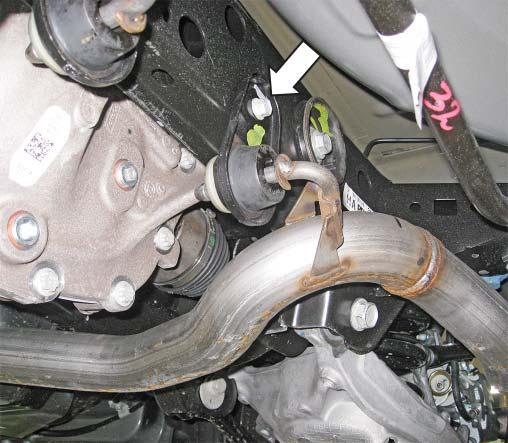
9 3. Unhook each exhaust hanger from the sub frame and remove each muffler assembly by sliding the inlets down and forward to extract the rear exhaust hangers from their mounts. QUAD TIP GT V8 EXHAUST INSTALLATION 1. With the rear wheels off of the ground remove and replace the rear sway bar bushing bolts one at a time with the new studs (P/N: W717354) that are found in the heat shield kit (P/N: EXHK). Install the heat shields (P/N: SHLD) with the nuts (P/N: NM8X125HF) that are included in the heat shield kit. 3. Drill all four (4) pilot holes that were marked in the previous step with a 1/8 drill bit followed by a 17/32 drill bit. 2. Locate the template onto the rear chassis sub frame as shown in the pictures below and mark the drill holes with a center punch. Use the same template to mark the holes on both the RH and LH sides of the vehicle AVIM-AA ROUSH
 rivet nuts (P/N: 95105A191) using the supplied bolt and nut from the")


 as shown below. Torque to 18 lb-ft (25 Nm). 6.")
10 4. Deburr the drilled holes and apply automotive clear coat. Install four (4) rivet nuts (P/N: 95105A191) using the supplied bolt and nut from the rivet nut installation kit (P/N: R HWK). Insert the nut onto the bolt and thread the bolt into the rivet nut. Hold the nut with a 17 mm wrench and tighten the bolt nut with a 10 mm socket until the rivet nut is fully seated. 5. Install the two (2) supplied exhaust hangers (P/N: A261 and G298) and four (4) bolts (P/N: W500224) as shown below. Torque to 18 lb-ft (25 Nm). 6. Remove the two (2) IRS sub frame mounted exhaust hangers from the stock exhaust system and slide them onto each side of the ROUSH exhaust AVIM-AA ROUSH
 followed by the block off plates and finally the outlet couplers onto both of the flanged")
 nuts (P/N: NM8X125HF) and torque to 18 lb-ft (25 Nm).")
 onto each outlet of the forward section of the factory exhaust. 8.")

11 7. Slide the rubber exhaust isolators (P/N: BR3Z-5A262) onto the rear muffler hangers. Install the block off gaskets (P/N: CV6Z-9450) followed by the block off plates and finally the outlet couplers onto both of the flanged outlets on the muffler assemblies (P/N: AVCV and AVCV). Secure the outlet couplers with the four (4) nuts (P/N: NM8X125HF) and torque to 18 lb-ft (25 Nm). Slide on the heat shield clamps (P/N: ). Slide the exhaust pipe clamps (P/N: ) onto each outlet of the forward section of the factory exhaust. 8. Install each side of the ROUSH exhaust system by inserting the rear exhaust hangers first and then sliding each side forward to fully seat the inlets with the forward section of the stock exhaust. Be sure to connect the rubber isolators to the hangers that were installed in step 7 and also reinstall the two (2) IRS sub frame exhaust hangers with the two (2) 13 mm bolts that were removed in step 2 and torque to 18 lb-ft (25 Nm). Tighten the heat shield clamps. Torque the exhaust pipe clamps to 35 lb-ft (47 Nm) AVIM-AA ROUSH

.")

 plastic nuts by hand, push the outer ends")

12 ACTIVE EXHAUST INSTALLATION 1. Begin the installation by first opening the hood and disconnecting the battery (refer to your owner s manual for guidance). Next open the trunk and remove the spare tire cover panel and rear trunk trim panel. To remove the rear trunk trim panel, loosen the four (4) plastic nuts by hand, push the outer ends forward towards the front of the vehicle and slide the panel upwards to release the remaining clips that are on the backside of the panel AVIM-AA ROUSH


 push pins along the driver")

13 3. Remove the bottom portion of the rear seat by pushing in on the latches that are under the front edge on each side and lifting the seat up. 4. Remove the door sill trim piece by first lifting up at the front corner and then disengaging the clips along the bottom. 2. Remove two (2) push pins along the driver side trunk carpet if your vehicle is a fastback. If your vehicle is a convertible, then you will need to remove three (3) push pins along the driver side trunk carpet. NOTE: Right-hand drive vehicles must mount the module on the right-hand side of the vehicle AVIM-AA ROUSH


14 5. Remove the rear quarter panel trim piece by first removing the seat belt guide trim ring and then firmly pulling inwards along the panel to disconnect the plastic clips along the back. NOTE: For fastback models, first release the upper portion of the rear seat and fold it down to gain access to the seat belt guide trim ring. NOTE: For convertible models, after removing the seat belt guide trim ring, remove the top trim piece by first lifting up at the front and disengaging the clips along the bottom. Now remove the quarter panel trim piece as previously instructed. 6. Remove the driver side trunk carpet AVIM-AA ROUSH


 and install it on the")

15 NOTE: For fastback models, first remove the push pin that is located near the driver side rear seat belt. NOTE: For convertible models, first remove the trunk light that is mounted in the driver side trunk carpet by pressing it out from the back. Location for convertible models shown below: 7. Locate the M6 J-Clip (P/N: 95210A175) that is in the Hardware Kit (P/N: AV) and install it on the driver side sheet metal in the trunk as shown below. Location for fastback models shown below: AVIM-AA ROUSH
 to the back of the")
 and locate the included rubber")

 and identify the following")

16 8. Apply the two (2) pieces of foam tape (P/N: E260TP) to the back of the active exhaust control module (P/N: E260) and locate the included rubber grommet as shown. Location for fastback models shown below: 9. Locate the active exhaust wiring harness (P/N: L430) and identify the following connectors. Active Module Connector Location for convertible models shown below: Active Module Relay AVIM-AA ROUSH


 that was installed in step 7.")


17 OBD Pigtail Connector 12V Outlet Connector Fuse Tap OBD Pigtail Active Switch Connector Active Valve Connector 10. Set the active exhaust wiring harness (P/N: L430) in the trunk and locate the large relay. Remove foam tape covering. Take the M6 x 31 bolt (P/N: R ) and insert it through the grommet on the control module followed by the mounting tab on the relay and then insert it into the M6 J-Clip (P/N: 95210A175) that was installed in step 7. Torque the bolt to 10 Nm and then plug the module connector from the wiring harness into the module. NOTE: Right-hand drive vehicles must mount the module on the right-hand side of the vehicle. Mounting location varies from pictures shown AVIM-AA ROUSH


 that has the grommet and feed the two (2) connectors")


18 Location for convertible models shown below: Location for fastback models shown below: 11. Remove the rubber cap that is on the passenger side of the spare tire well. Locate the section of the active exhaust wiring harness (P/N: L430) that has the grommet and feed the two (2) connectors through the hole in the spare tire well that the rubber cap was removed from. Fully seat the grommet from the active exhaust wiring harness into the sheet metal of the trunk floor. 12. Remove the 8 mm bolt from the factory ground at the rear of the trunk as well as the push-in retainer from the factory wiring harness AVIM-AA ROUSH
 and then reinstall it with the factory")


 and")

19 13. Insert the 8 mm bolt into the ring terminal on the active exhaust wiring harness (P/N: L430) and then reinstall it with the factory ground into the position it was removed from in step 12 and torque to 2 Nm. Insert the push-in retainer from the factory wiring harness into the ring clip from the active exhaust wiring harness and then reinstall the push-in retainer into the position it was removed from in step Route the wiring harness along the driver side of the trunk into the cabin and secure with both the standard 7" zip ties (P/N: CTUV740) and the zip ties with edge clips (P/N: ) as shown below. Trim the tails of the zip ties once they are secure AVIM-AA ROUSH


 clips along the door jam and one (1) push pin at the front that need to be released in order to")
20 15. Re-install the driver side trunk carpet (and trunk light, if equipped). Re-install the rear trunk trim panel by reversing the removal process outlined in step 2. Re-install the spare tire cover panel. 16. Continue routing the wiring harness along the driver side of the vehicle and secure with the standard 7" zip ties (P/N: CTUV740) as shown. 18. Remove the driver side kick panel. Start by prying out the center cap in the hood release handle with a small pick and then releasing the inner tabs with a small flat-head screwdriver to remove the handle. There are also two (2) clips along the door jam and one (1) push pin at the front that need to be released in order to remove the panel. The hood release handle is not applicable on righthand drive vehicles. 17. Remove the lower driver side dash trim panel with a non-marring trim tool. Gently pry the trim piece out to release the clips on the backside AVIM-AA ROUSH
")


21 20. Remove the two (2) push pins that secure the carpet to the wire harness housing along the door sill and remove the two (2) 10 mm fasteners that secure the door sill wire harness housing to the vehicle. Pull the housing back to reveal the factory sections of tape and carefully remove or cut each section of tape along the outer edge of the wire harness housing. 19. Remove the bottom portion of the door seal. Disconnect the electrical connector for the illuminated door sill plates. Remove the two (2) metal clips along the seam in the sheet metal. Remove the zip ties from the door sill cover AVIM-AA ROUSH


22 21. Route the active exhaust wire harness along the outside of the factory wiring harness in the wire harness housing. Close the wire harness housing and apply new sections of tape to secure it closed AVIM-AA ROUSH
 10 mm fasteners that secure the door sill wire harness housing which were")
 push pins that retain the carpet to the wire harness housing that were removed")


 7 mm fasteners on each side of the console once the trim pieces are removed. 25.")
23 22. Reinstall the two (2) metal clips onto the sheet metal seam that were removed in step 19. Reinstall the two (2) 10 mm fasteners that secure the door sill wire harness housing which were removed in step 19 and torque to 2 Nm. Reinstall the two (2) push pins that retain the carpet to the wire harness housing that were removed in step Re-install the rear quarter trim panel and the bottom portion of the rear seat by reversing the process outlined in steps 4 and Remove the side trim pieces along the center console by lifting the front lower corners and carefully disengage the retaining clips along the back. Remove two (2) 7 mm fasteners on each side of the console once the trim pieces are removed. 25. Remove the molded rubber tray from in front of the shifter. 26. Using a non-marring trim tool, gently lift each of the rear corners of the center console and disengage the retaining clips along the bottom from the rear all the way up to the front AVIM-AA ROUSH


.")


24 28. Release the clips for the shifter trim bezel and remove the top section of the center console from the vehicle. 27. With the emergency brake fully engaged, lift the top portion of the center console up and unplug the connectors for the key fob detection circuit and for the cup holder lighting (if equipped). Pull back on the center console to release the clips. 29. Continue routing the wire harness up through the driver side kick panel area and secure as shown below AVIM-AA ROUSH


25 31. Continue routing the wiring harness along the dash structure up through to the center console and secure with the standard 7" zip ties (P/N: CTUV740) as shown below. 30. Plug the OBDII pass-through connector that is part of the active exhaust wiring harness (P/N: L430) into the OBDII connector that is under the dash. Secure the connector with two (2) standard 7" zip ties (P/N: CTUV740) as shown below. 32. Unplug the connector for the 12-volt power outlet that is in the center console. Using a small pick, remove the red locking piece that is in the end of the connector. Carefully lift the tab for the grey with orange wire in the connector and remove the terminal from the connector AVIM-AA ROUSH
 and press the red lock in the front of the connector to lock it in place. 36.")


26 35. Check to make sure all the connections are fully seated, slide the seal into place as well as the rear clip. Plug the connector into the active exhaust wiring harness (P/N: L430) and press the red lock in the front of the connector to lock it in place. 36. Plug the factory 12-volt power outlet connector back into the 12-volt outlet in the center console and route the active exhaust wiring harness in the center console as shown. 33. Take the yellow lead from the active exhaust wiring harness (P/N: L430) that has the same terminal on the end and insert it into the spot in the 12-volt power outlet connector that was de-pinned in step 32. Replace the red locking piece that was in the end of the connector. 34. Remove the rear clip and seal from the new connector that is bagged and taped to the active exhaust harness. Insert the clip and then the seal onto the grey with orange wire that was removed from the 12-volt power outlet connector and then insert into the new connector as shown below. 37. Locate the lead on the active exhaust wiring harness with the fuse tap on the end and route it outside of the console along the dash structure up to the passenger side kick panel and secure the harness with standard 7" zip ties (P/N: CTUV740) as shown AVIM-AA ROUSH
 and install it onto the switch bracket (P/N: 1315-7Z374) with two (2) M4 screws (P/N:")
 from the fuse panel.")
 that is part of the hardware kit (P/N: 1315-5231AV) and plug that into the additional spot in the fuse")

27 39. Reinstall the fuse panel cover. 40. Locate the active exhaust switch (P/N: K724) and install it onto the switch bracket (P/N: Z374) with two (2) M4 screws (P/N: 90116A207), torque to 1 Nm. Install the O-ring (P/N: 9262K215) onto the switch post. 38. Remove the fuse panel cover in the passenger kick panel area and remove fuse #23 (10 amp) from the fuse panel. Plug the 10-amp fuse into the fuse tap that is located in the active exhaust wiring harness (P/N: L430). Locate the 10-amp fuse (P/N: ATP-10A) that is part of the hardware kit (P/N: AV) and plug that into the additional spot in the fuse tap. Plug the fuse tap into slot #23 that the 10-amp fuse was originally removed from. Right-hand drive vehicles will have extra length on the fuse tap harness. The harness can be zip tied up out of the path of the airbag or it can be cut and reduced in length. 41. Trim out the drill template that is located on the last page of this installation manual. 42. With the top section of the center console placed in a safe area, tape the drill template into position as shown AVIM-AA ROUSH
 through the holes that were drilled in step 43.")
 3/16\" push nuts.")
 into the mating")

28 43. Mark the four (4) holes with a center punch and drill them with the appropriate sized drill bits as indicated by the template (1/4"). 44. Remove the template and insert the studs on the active exhaust switch plate (P/N: ) through the holes that were drilled in step 43. Turn the console over and insert two (2) M4 nylon washers (P/N: 91755A215) onto the front stud of the switch plate and (1) nylon washer (P/N: 91755A215) onto the rear stud of the switch plate. Insert the switch and bracket assembly onto the switch plate studs and carefully secure with two (2) 3/16" push nuts. A deep 7 mm socket works well to drive the push nuts onto the studs. Check to make sure the entire assembly is fully seated and that there is no play in any of the components. 45. Reinstall the top section of the center console and the side trim pieces by reversing steps while being sure to plug the active exhaust switch (P/N: K724) into the mating connector in the active exhaust wiring harness (P/N: L430). Torque the 7 mm fasteners to 2 Nm. 46. Reinstall the driver side kick panel and the lower driver side dash trim panel by reversing steps Reinstall the door sill trim piece that was removed in step Locate the active exhaust switch knob (P/N: 1315-AVKNOB) and the set screw (P/N: 92311A106) which can both be found in the Hardware Kit (P/N: AV) and loosely install the set screw into the threaded hole on the side of the knob AVIM-AA ROUSH


![Slide each exhaust tip (P/N: 1318-AVTIPLH [left hand] and 1318-AVTIPRH [right hand]) onto the muffler outlets with the exhaust tip clamps (P/N: 10-0338).](/docs-images/87/96186625/images/29-2.jpg "Align the tips to the rear valance. Torque the exhaust tip clamps to 35 lb-ft (47 Nm).")

29 49. Insert the knob onto the active exhaust switch post. Align the small flat on the switch post to be perpendicular to the set screw. Seat the knob fully onto the switch post and torque the set screw to 1 Nm. 50. Locate the active exhaust valve assemblies (P/N s: LH and RH) and install them in place of the straight outlet couplers that are included on the ROUSH Quad Tip Exhaust. Reuse the existing gaskets, nuts, tips and clamps. Torque the nuts to 25 Nm and torque the clamps for the exhaust tips to 47 Nm. 51. Slide each exhaust tip (P/N: 1318-AVTIPLH [left hand] and 1318-AVTIPRH [right hand]) onto the muffler outlets with the exhaust tip clamps (P/N: ). Align the tips to the rear valance. Torque the exhaust tip clamps to 35 lb-ft (47 Nm). NOTE: If your vehicle is a convertible be sure to reinstall the rear sub frame by reversing step 1 titled Rear Sub Frame Removal Locate the wiring harness that is routed through the grommet in the trunk floor. Route the short lead to the passenger side valve and the long lead to the driver side valve. 54. Secure the wiring to the sheet metal edge under the vehicle using the edge clips with zip ties (P/N: ) as shown below and plug the respective connectors into each valve AVIM-AA ROUSH


30 55. Reconnect the battery, start the vehicle and test your new ROUSH active exhaust. Congratulations, the installation is complete! AVIM-AA ROUSH
31 DRILL TEMPLATES 2" (50.8 MM) 4X 0.25" 2" SWITCH PLATE TEMPLATE Note: Print this page at 100% scale and verify that the drill template has printed properly by measuring it after it is printed AVIM-AA ROUSH
ROUSH Active IO Exhaust. Installation Instructions P/N: (R LITE) Fastback GT Convertible GT V8
 Fastback GT Convertible GT V8") Installation Instructions P/N: 422128 (R1318-5231LITE) Fastback GT Convertible GT V8 39555 Schoolcraft Rd, Plymouth MI, 48170 800.59.ROUSH ROUSH Active IO Exhaust Installation Instructions P/N: 422128
Installation Instructions P/N: 422128 (R1318-5231LITE) Fastback GT Convertible GT V8 39555 Schoolcraft Rd, Plymouth MI, 48170 800.59.ROUSH ROUSH Active IO Exhaust Installation Instructions P/N: 422128
ROUSH Quad Tip Exhaust Installation Instructions P/N:
 Installation Instructions P/N: 421920 421921 421922 421923 39555 Schoolcraft Rd, Plymouth MI, 48170 800.59.ROUSH ROUSH Quad Tip Exhaust Installation Instructions P/N: 421920 (R1315-5231PV) Fastback GT
2015+ F-150 Active Exhaust Kit Installation Instructions P/N: (1117-5E292LITE)
") 2015+ F-150 Active Exhaust Kit Installation Instructions P/N: 422104 (1117-5E292LITE) 39555 Schoolcraft Rd, Plymouth MI, 48170 800.59.ROUSH 2015+ Ford F-150 Active Exhaust Kit Installation Instructions
2015+ F-150 Active Exhaust Kit Installation Instructions P/N: 422104 (1117-5E292LITE) 39555 Schoolcraft Rd, Plymouth MI, 48170 800.59.ROUSH 2015+ Ford F-150 Active Exhaust Kit Installation Instructions
ROUSH Convertible Stylebar Installation Instructions P/N: (1315-STYLEBAR) Convertible Only
 Convertible Only") Installation Instructions P/N: 421911 (1315-STYLEBAR) Convertible Only 39555 Schoolcraft Rd, Plymouth MI, 48170 800.59.ROUSH Installation Instructions P/N: 421911 (1315-STYLEBAR) Convertible Only Application:
Installation Instructions P/N: 421911 (1315-STYLEBAR) Convertible Only 39555 Schoolcraft Rd, Plymouth MI, 48170 800.59.ROUSH Installation Instructions P/N: 421911 (1315-STYLEBAR) Convertible Only Application:
2015+ Mustang Rear Valance Installation Instructions P/N: (R F953) (R F953BS)
 (R F953BS)") 2015+ Mustang Rear Valance Installation Instructions P/N: 421894 (R1315-17F953) 421919 (R1315-17F953BS) 39555 Schoolcraft Rd, Plymouth MI, 48170 800.59.ROUSH 2015+ Mustang Rear Valance Kit Installation
2015+ Mustang Rear Valance Installation Instructions P/N: 421894 (R1315-17F953) 421919 (R1315-17F953BS) 39555 Schoolcraft Rd, Plymouth MI, 48170 800.59.ROUSH 2015+ Mustang Rear Valance Kit Installation
2015 Mustang Heat Extractors Installation Instructions P/N: (R C920)
") Installation Instructions P/N: 421869 (R1315-16C920) 39555 Schoolcraft Rd, Plymouth MI, 48170 800.59.ROUSH 2015 Mustang Heat Extractors Installation Instructions P/N: 421869 (R1315-16C920) Application:
Installation Instructions P/N: 421869 (R1315-16C920) 39555 Schoolcraft Rd, Plymouth MI, 48170 800.59.ROUSH 2015 Mustang Heat Extractors Installation Instructions P/N: 421869 (R1315-16C920) Application:
2015+ Mustang I-4 Y-Pipe Exhaust Kit Installation Instructions P/N: (1315-5G206)
") 2015+ Mustang I-4 Y-Pipe Exhaust Kit Installation Instructions P/N: 422091 (1315-5G206) 39555 Schoolcraft Rd, Plymouth MI, 48170 800.59.ROUSH 2015+ Mustang I-4 Y-Pipe Exhaust Kit Installation Instructions
2015+ Mustang I-4 Y-Pipe Exhaust Kit Installation Instructions P/N: 422091 (1315-5G206) 39555 Schoolcraft Rd, Plymouth MI, 48170 800.59.ROUSH 2015+ Mustang I-4 Y-Pipe Exhaust Kit Installation Instructions
Mustang 5.0L Cold Air Intake Installation Instructions P/N:
 2015-2017 Mustang 5.0L Cold Air Intake Installation Instructions P/N: 421826 39555 Schoolcraft Rd, Plymouth MI, 48170 800.59.ROUSH 2015-2017 Mustang 5.0L Cold Air Intake Installation Instructions P/N:
2015+ Mustang Trunk Toolkit Installation Instructions P/N: (R1315-TOOLKIT)
") Installation Instructions P/N: 421910 (R1315-TOOLKIT) 39555 Schoolcraft Rd, Plymouth MI, 48170 800.59.ROUSH 2015+ Mustang Trunk Toolkit Installation Instructions P/N: 421910 (R1315-TOOLKIT) Important Note:
Installation Instructions P/N: 421910 (R1315-TOOLKIT) 39555 Schoolcraft Rd, Plymouth MI, 48170 800.59.ROUSH 2015+ Mustang Trunk Toolkit Installation Instructions P/N: 421910 (R1315-TOOLKIT) Important Note:
ROUSH Cat Back Exhaust
 ROUSH Cat Back Exhaust Installation Instructions 2015-2018 2.3L I-4 P/N: 422094 (1315-5G203) 2015-2017 5.0L V8 P/N: 422092 (1315-5G201) 2018 5.0L V8 P/N: 422093 (1318-5G202) 39555 Schoolcraft Rd, Plymouth
2015 Mustang Fastback Rear Spoiler Installation Instructions P/N:
 Installation Instructions P/N: 421883 421884 421885 421886 421887 421888 421889 421890 421891 421892 421893 39555 Schoolcraft Rd, Plymouth MI, 48170 800.59.ROUSH 2015 Mustang Fastback Rear Spoiler Installation
2018 Mustang 5.0L Cold Air Intake Installation Instructions P/N: ( )
") Installation Instructions P/N: 422086 (131850-9600) 39555 Schoolcraft Rd, Plymouth MI, 48170 800.59.ROUSH 2018 Mustang 5.0L Cold Air Intake Installation Instructions P/N: 422086 (131850-9600) Application:
Installation Instructions P/N: 422086 (131850-9600) 39555 Schoolcraft Rd, Plymouth MI, 48170 800.59.ROUSH 2018 Mustang 5.0L Cold Air Intake Installation Instructions P/N: 422086 (131850-9600) Application:
Mustang V-6 Cold Air Intake P/N: ( A600) Application: Ford Mustang 3.7L Manual or Automatic Transmission
 Application: Ford Mustang 3.7L Manual or Automatic Transmission") 2015-2017 Mustang V-6 Cold Air Intake P/N: 421828 (131537-9A600) Application: 2015-2017 Ford Mustang 3.7L Manual or Automatic Transmission Installation Instructions Before installing your ROUSH Performance
2015-2017 Mustang V-6 Cold Air Intake P/N: 421828 (131537-9A600) Application: 2015-2017 Ford Mustang 3.7L Manual or Automatic Transmission Installation Instructions Before installing your ROUSH Performance
2015+ Mustang GT V8 X-Pipe Exhaust Kit Installation Instructions P/N: (99-137)
") 2015+ Mustang GT V8 X-Pipe Exhaust Kit Installation Instructions P/N: 422046 (99-137) 39555 Schoolcraft Rd, Plymouth MI, 48170 800.59.ROUSH 2015+ Mustang GT V8 X-Pipe Exhaust Kit Installation Instructions
2015+ Mustang GT V8 X-Pipe Exhaust Kit Installation Instructions P/N: 422046 (99-137) 39555 Schoolcraft Rd, Plymouth MI, 48170 800.59.ROUSH 2015+ Mustang GT V8 X-Pipe Exhaust Kit Installation Instructions
2015+ Mustang GT V8 X-Pipe/H-Pipe Exhaust Kit Installation Instructions
 2015+ Mustang GT V8 X-Pipe/H-Pipe Exhaust Kit Installation Instructions P/N: 422046 and 422119 39555 Schoolcraft Rd, Plymouth MI, 48170 800.59.ROUSH 2015+ Mustang GT V8 X-Pipe/H-Pipe Exhaust Kit Installation
Mustang Hood Scoop
 Installation Instructions P/N: 421858 421859 421860 421861 421862 421863 421864 421865 421866 421867 421868 422055 422056 422057 39555 Schoolcraft Rd, Plymouth MI, 48170 800.59.ROUSH 2015-2017 Mustang
Mustang V-6 Level 1 Performance Pack Installation Instructions P/N: ( PWRPK1-AA)
") 2015-2017 Mustang V-6 Level 1 Performance Pack Installation Instructions P/N: 421999 (131537-PWRPK1-AA) 39555 Schoolcraft Rd, Plymouth MI, 48170 800.59.ROUSH 2015-2017 Mustang V-6 Level 1 Performance Pack
2015-2017 Mustang V-6 Level 1 Performance Pack Installation Instructions P/N: 421999 (131537-PWRPK1-AA) 39555 Schoolcraft Rd, Plymouth MI, 48170 800.59.ROUSH 2015-2017 Mustang V-6 Level 1 Performance Pack
2018+ Mustang Hood Heat Extractors Installation Instructions P/N: (R C920)
") 2018+ Mustang Hood Heat Extractors Installation Instructions P/N: 422083 (R1318-16C920) 39555 Schoolcraft Rd, Plymouth MI, 48170 800.59.ROUSH 2018+ Mustang Hood Heat Extractors Installation Instructions
2018+ Mustang Hood Heat Extractors Installation Instructions P/N: 422083 (R1318-16C920) 39555 Schoolcraft Rd, Plymouth MI, 48170 800.59.ROUSH 2018+ Mustang Hood Heat Extractors Installation Instructions
F L NA Cold Air Intake Installation Instructions P/N: ( )
") 2015-2017 F-150 3.5L NA Cold Air Intake Installation Instructions P/N: 421982 (111535-9600) 39555 Schoolcraft Rd, Plymouth MI, 48170 800.59.ROUSH 2015-2017 F-150 3.5L NA Cold Air Intake Installation Instructions
2015-2017 F-150 3.5L NA Cold Air Intake Installation Instructions P/N: 421982 (111535-9600) 39555 Schoolcraft Rd, Plymouth MI, 48170 800.59.ROUSH 2015-2017 F-150 3.5L NA Cold Air Intake Installation Instructions
2018 F L Cold Air Intake Installation Instructions P/N: ( )
") Installation Instructions P/N: 422088 (111850-9600) 39555 Schoolcraft Rd, Plymouth MI, 48170 800.59.ROUSH 2018 F-150 5.0L Cold Air Intake Installation Instructions P/N: 422088 (111850-9600) Application:
Installation Instructions P/N: 422088 (111850-9600) 39555 Schoolcraft Rd, Plymouth MI, 48170 800.59.ROUSH 2018 F-150 5.0L Cold Air Intake Installation Instructions P/N: 422088 (111850-9600) Application:
2018 Mustang 5.0L Performance PAC1 Installation Instructions P/N: ( PERFPK1)
") 2018 Mustang 5.0L Performance PAC1 Installation Instructions P/N: 422113 (131850-PERFPK1) 39555 Schoolcraft Rd, Plymouth MI, 48170 800.59.ROUSH 2018 Mustang 5.0L Performance PAC1 Installation Instructions
2018 Mustang 5.0L Performance PAC1 Installation Instructions P/N: 422113 (131850-PERFPK1) 39555 Schoolcraft Rd, Plymouth MI, 48170 800.59.ROUSH 2018 Mustang 5.0L Performance PAC1 Installation Instructions
2015 Mustang Quarter Window Scoop Installation Instructions P/N: (R UA)
") 2015 Mustang Quarter Window Scoop Installation Instructions P/N: 421881 (R1315-011104UA) 39555 Schoolcraft Rd, Plymouth MI, 48170 800.59.ROUSH 2015 Mustang Quarter Window Scoop Installation Instructions
2015 Mustang Quarter Window Scoop Installation Instructions P/N: 421881 (R1315-011104UA) 39555 Schoolcraft Rd, Plymouth MI, 48170 800.59.ROUSH 2015 Mustang Quarter Window Scoop Installation Instructions
2015+ Ford F-150 Off-Road Exhaust Kit
 2015+ Ford F-150 Off-Road Exhaust Kit Installation Instructions P/N: 421985 (1115-5E292ORR) Application: 2015+ Ford F-150 OFF-ROAD USE ONLY Important Note: Before installing the ROUSH Performance Product,
F L Ecoboost V F L Ecoboost V6 Performance Pac Level 2 Installation Instructions P/N: (1115TT-PWRPK2)
") 2015-2016 F-150 3.5L Ecoboost V6 2015-2017 F-150 2.7L Ecoboost V6 Performance Pac Level 2 Installation Instructions P/N: 422007 (1115TT-PWRPK2) 39555 Schoolcraft Rd, Plymouth MI, 48170 800.59.ROUSH 2015-2016
2015-2016 F-150 3.5L Ecoboost V6 2015-2017 F-150 2.7L Ecoboost V6 Performance Pac Level 2 Installation Instructions P/N: 422007 (1115TT-PWRPK2) 39555 Schoolcraft Rd, Plymouth MI, 48170 800.59.ROUSH 2015-2016
2015 Mustang Ecoboost Cold Air Intake
 2015 Mustang Ecoboost Cold Air Intake Installation Instructions P/N: 421827 (131523-9A600) Application: 2015 Ford Mustang 2.3L Manual or Automatic Transmission Important Note: Before installing the ROUSH
2018 Mustang Ecoboost Cold Air Intake P/N: ( ) Application: 2018 Ford Mustang 2.3L Manual or Automatic Transmission
 Application: 2018 Ford Mustang 2.3L Manual or Automatic Transmission") 2018 Mustang Ecoboost Cold Air Intake P/N: 422087 (131823-9600) Application: 2018 Ford Mustang 2.3L Manual or Automatic Transmission Installation Instructions Before installing your ROUSH Performance Product(s),
2018 Mustang Ecoboost Cold Air Intake P/N: 422087 (131823-9600) Application: 2018 Ford Mustang 2.3L Manual or Automatic Transmission Installation Instructions Before installing your ROUSH Performance Product(s),
2015+ Mustang LoudMouth I and LoudMouth II Exhaust Kits
 2015+ Mustang LoudMouth I and Installation Instructions P/N: 620054, 620055, 620061, 620062 (S1315-5231LM1, S1315-5231LM2, S1315S1-5231LM1, S1315S1-5231LM2) *LoudMouth II shown. BY 39555 Schoolcraft Rd,
2016+ Camaro V8 or V6/I4 Exhaust Kit
 2016+ Camaro V8 or V6/I4 Exhaust Kit Installation Instructions P/N: 620079 (99-135) P/N: 620078 (99-136) 39555 Schoolcraft Rd, Plymouth MI, 48170 855.SLP.PERF 2016+ Camaro V8 or V6/I4 Exhaust Kit Installation
F L and 2.7L Ecoboost V6
 2015-2016 F-150 3.5L and 2.7L Ecoboost V6 Installation Instructions P/N: 421981 (1115TT-9600) Application: 2015-2016 Ford F-150 2.7L Ecoboost V6, 2015-2016 Ford F-150 3.5L Ecoboost V6 Important Note: Before
2015+ Ford F-150 Windshield Banner Kit Installation Instructions P/N: (R )
") 2015+ Ford F-150 Windshield Banner Kit Installation Instructions P/N: 422016 (R1115-03088) 39555 Schoolcraft Rd, Plymouth MI, 48170 800.59.ROUSH 2015+ F-150 Windshield Banner Installation Instructions
2015+ Ford F-150 Windshield Banner Kit Installation Instructions P/N: 422016 (R1115-03088) 39555 Schoolcraft Rd, Plymouth MI, 48170 800.59.ROUSH 2015+ F-150 Windshield Banner Installation Instructions
2015+ Mustang Windshield Banner Installation Instructions P/N: (R )
") Installation Instructions P/N: 421903 (R1315-03088) 39555 Schoolcraft Rd, Plymouth MI, 48170 800.59.ROUSH 2015+ Mustang Windshield Banner Installation Instructions P/N: 421903 (R1315-03088) Application:
Installation Instructions P/N: 421903 (R1315-03088) 39555 Schoolcraft Rd, Plymouth MI, 48170 800.59.ROUSH 2015+ Mustang Windshield Banner Installation Instructions P/N: 421903 (R1315-03088) Application:
2018+ Mustang Lower Grill and Chin Spoiler Kits Installation Instructions P/N: (R K945) P/N: (R F775)
 P/N: (R F775)") 2018+ Mustang Lower Grill and Chin Spoiler Kits Installation Instructions P/N: 422081 (R1318-17K945) P/N: 422082 (R1318-17F775) 39555 Schoolcraft Rd, Plymouth MI, 48170 800.59.ROUSH 2018+ Mustang Lower
2018+ Mustang Lower Grill and Chin Spoiler Kits Installation Instructions P/N: 422081 (R1318-17K945) P/N: 422082 (R1318-17F775) 39555 Schoolcraft Rd, Plymouth MI, 48170 800.59.ROUSH 2018+ Mustang Lower
2012+ Focus Focus ST ROUSH Cold Air Induction Kit(s)
") 2012+ Focus 2013+ Focus ST ROUSH Cold Air Induction Kit(s) P/N: 421642 (1213NA-9600) 421609 (1213ST-9600) Installation Instructions Before installing your ROUSH Performance Product(s), read through the
2012+ Focus 2013+ Focus ST ROUSH Cold Air Induction Kit(s) P/N: 421642 (1213NA-9600) 421609 (1213ST-9600) Installation Instructions Before installing your ROUSH Performance Product(s), read through the
2014+ GM Truck Cat Back Exhaust Kit 4.3L/5.3L/6.2L
 2014+ GM Truck Cat Back Exhaust Kit 4.3L/5.3L/6.2L Installation Instructions P/N: 620074 (99-47) 4.3L/5.3L P/N: 620080 (99-139) 6.2L 39555 Schoolcraft Rd, Plymouth MI, 48170 855.SLP.PERF 2014+ GM Truck
ROUSH FUEL SYSTEM UPGRADE CURRENT FORD MUSTANG 5.0L
 ROUSH FUEL SYSTEM UPGRADE 2011- CURRENT FORD MUSTANG 5.0L P/N: 421602 (1313-FPVRKIT) Installation Instructions Before installing your ROUSH Performance Product(s), read through the entire installation
2015+ Mustang Shift Ball Installation Instructions P/N: (R BLK) P/N: (R WHT)
 P/N: (R WHT)") 2015+ Mustang Shift Ball Installation Instructions P/N: 421906 (R1315-7213 BLK) P/N: 421907 (R1315-7213 WHT) 39555 Schoolcraft Rd, Plymouth MI, 48170 800.59.ROUSH 2015+ Mustang Shift Ball Installation
2015+ Mustang Shift Ball Installation Instructions P/N: 421906 (R1315-7213 BLK) P/N: 421907 (R1315-7213 WHT) 39555 Schoolcraft Rd, Plymouth MI, 48170 800.59.ROUSH 2015+ Mustang Shift Ball Installation
Ford F-150 Off Road Exhaust Kit
 2011-14 Ford F-150 Off Road Exhaust Kit P/N: 620092 (SLP1111-5E292) Application: 2011-14 Ford F-150 equipped with the following engine options: 3.5L Eco-Boost Engine with automatic transmission. 5.0L 4V
Front Fascia Kit Installation Instructions P/N:
 Installation Instructions P/N: 421843 421844 421845 421846 421847 421848 421849 421850 421851 421852 421853 39555 Schoolcraft Rd, Plymouth MI, 48170 800.59.ROUSH 2015-2017 Front Fascia Kit Installation
Installation Instructions
 SLP GM/Chevrolet LS3 COIL COVER KIT 2010+ Camaro 5.3L/6.2L 2007+ GMT900 5.3L/6.2L PN: 620038 Installation Instructions Important Notes: Before installing your SLP Coil Cover Kit, please read the installation
ROUSH Short Throw Shifter Kit
 ROUSH Short Throw Shifter Kit Part Number 1310R7400 Application: 2010 Ford Mustang GT Installation Instructions Before installing your ROUSH Performance Product(s), read through the entire installation
Before installing your Roush Performance Product(s), read through the entire installation procedure and check to make sure all items are present.
, read through the entire installation procedure and check to make sure all items are present.") 2005-2006 Ford Mustang GT Legal / Stage 3 / Offroad Exhaust Kits for Roush Rear Valence Installation Instructions Application: 2005- Ford Mustang GT Model Must have Roush Rear Valence Kit #R03030061 Before
2005-2006 Ford Mustang GT Legal / Stage 3 / Offroad Exhaust Kits for Roush Rear Valence Installation Instructions Application: 2005- Ford Mustang GT Model Must have Roush Rear Valence Kit #R03030061 Before
Before installing your Roush Performance Product(s), read through the entire installation procedure and check to make sure all items are present.
, read through the entire installation procedure and check to make sure all items are present.") Ford Mustang Roush Fog Lamp Wiring Harness Installation Instructions Application: 2005 Ford Mustang GT Model (Designed for use with Roush Fog Lamps SM01-6400-AL) Before installing your Roush Performance
Ford Mustang Roush Fog Lamp Wiring Harness Installation Instructions Application: 2005 Ford Mustang GT Model (Designed for use with Roush Fog Lamps SM01-6400-AL) Before installing your Roush Performance
Installation Instructions
 2012-2014 Ford F-150 ROUSH Phase 1 Kit 3.5L V6 Eco-Boost P/N: 421735 (1135-P1CAL) Installation Instructions Before installing your ROUSH Cold Air Kit, please read through the entire installation procedure
M-9603-CJ 123 mm Cold Air Kit for 5.4L 4V V8 Cobra Jet Mustang INSTALLATION INSTRUCTIONS
 Please contact the Techline for the most current instruction information 1-800-367-3788.!!! PLEASE READ THE FOLLOWING INSTRUCTIONS CAREFULLY PRIOR TO INSTALLATION!!! OVERVIEW: This kit is designed for
Ford Mustang Rear Decklid Spoiler Kit. Installation Instructions
 Ford Mustang Rear Decklid Spoiler Kit Application: 2005-09 Ford Mustang Installation Instructions Before installing your ROUSH Performance Product(s), read through the entire installation procedure and
2013 Mustang Chin Splitter
 2013 Mustang Chin Splitter P/N: 421391 (R1313-17F775-AA) Application: 2013 Ford Mustang 2013 Mustang 5.0L with Automatic/Manual Transmission 2013 Mustang 3.7L with Automatic/Manual Transmission Installation
Ford Mustang Side Rocker Molding Installation Instructions Application: Ford Mustang
 Ford Mustang Side Rocker Molding Installation Instructions Application: 2005-07 Ford Mustang Before installing your Roush Performance Product(s), read through the entire installation procedure and check
2014 GM Truck Level 1 Performance Pack
 2014 GM Truck Level 1 Performance Pack Installation Instructions P/N: 2414-PRFPC1-AA Application: 2014+ Chevy Silverado and GMC Sierra 5.3L and 6.2L Important Note: Before installing your Blackwing cold
ROUSH Billet Upper Grille Kit
 ROUSH Billet Upper Grille Kit Part Number R03010141 Application: 2010-11 Mustang GT Installation Instructions Before installing your ROUSH Performance Product(s), read through the entire installation procedure
2013+ Focus ST Focus ROUSH Exhaust Kit
 2013+ Focus ST 2011 + Focus ROUSH Exhaust Kit P/N: 421610 (1213-5E292) Application: 2013+ Ford Focus ST 2011 + Ford Focus Installation Manual Before installing your ROUSH Performance Product(s), read through
ROUSH Front Splitter Kit
 ROUSH Front Splitter Kit Kit Part Number 1310010803 Application: 2010-11 ROUSH Mustang Note: Splitter only fits onto the 2010-11 ROUSH Front Fascia. Installation Instructions Before installing your ROUSH
ROUSH Performance Air Induction Kit Pt # Installation Instructions
 ROUSH Performance Air Induction Kit Pt #11099600 Application: 2009 Ford F-150 with 4.6L and 5.4L V8 Engines 2008-09 Ford F-250/F-350 Super Duty with 5.4L V8 and 6.8L V10 Engines For Off Road Use Only Installation
2011+ Ford F-150 ROUSH Cold Air Kit for the V6 Engine Family 3.7L 4V Ti-VCT ( ) Installation Instructions
 Installation Instructions") 2011+ Ford F-150 ROUSH Cold Air Kit for the V6 Engine Family 3.7L 4V Ti-VCT (1135-9600) Installation Instructions Before installing your ROUSH Cold Air Kit, please read through the entire installation
2011+ Ford F-150 ROUSH Cold Air Kit for the V6 Engine Family 3.7L 4V Ti-VCT (1135-9600) Installation Instructions Before installing your ROUSH Cold Air Kit, please read through the entire installation
SCION xd INTERIOR LIGHTING UPGRADE Preparation
 Preparation Part Number: PTS21-52085 Light Guide Kit Contents Item # Quantity Reqd. Description 1 1 Controller Board, 4 color programmed w/ Bracket 2 1 RGB, LED Engine wire harness 3 2 14mm Light Rod,
ROUSH Billet Lower Grille Kit
 ROUSH Billet Lower Grille Kit Kit Part Number 1310R8200B Application: 2010 ROUSH Mustang w/roush Front Fascia Installation Instructions Before installing your ROUSH Performance Product(s), read through
ROUSH Front Fascia Kit
 ROUSH Front Fascia Kit Kit Part Number 1310011901 Application: 2010-2012 Ford Mustang GT Installation Instructions Before installing your ROUSH Performance Product(s), read through the entire installation
YARIS 4-DOOR 2007 INTERIOR LIGHT UPGRADE
 Document # 3999 4/26/06 4-DOOR 2007 INTERIOR LIGHT UPGRADE Preparation Part Number: 00016-52060 Code: IL1 Kit Contents Item # Quantity Reqd. Description 1 1 12 Light Guide 2 1 7 Light Guide 3 1 Hardware
M-9603-GTB 85 mm Cold Air Kit w/premium Cal. for 4.6L 3V V8 Mustang INSTALLATION INSTRUCTIONS
 Please contact the Techline for the most current instruction information 800-367-3788.!!! PLEASE READ THE FOLLOWING INSTRUCTIONS CAREFULLY PRIOR TO INSTALLATION!!! OVERVIEW: This kit is designed for use
TOYOTA YARIS HATCHBACK INTERIOR LIGHT UPGRADE Preparation
 Preparation Part Number PTS21-52062-08 NOTE: Part number of this accessory may not be the same as the part number show Kit Contents Item # Quantity Reqd. Description 1 1 12 Light Guide 2 1 7 Light Guide
ROUSH Performance Air Induction Kit Pt # R
 ROUSH Performance Air Induction Kit Pt # R07060087 C. A. R. B. EO # D-418-14 See Important EO Note below Included with your ROUSH Intake System Kit is a sticker with a California Air Resources Board (C.
Mustang Billet Aluminum Pedal Cover Kit P/N R (Manual) and R (Automatic) Installation Instructions
 and R (Automatic) Installation Instructions") 2005-06 Mustang Billet Aluminum Pedal Cover Kit P/N R08050020 (Manual) and R08050021 (Automatic) Installation Instructions 1305-R08050026-AA Page 1 of 7 1-800-59-ROUSH Before installing this Roush Performance
2005-06 Mustang Billet Aluminum Pedal Cover Kit P/N R08050020 (Manual) and R08050021 (Automatic) Installation Instructions 1305-R08050026-AA Page 1 of 7 1-800-59-ROUSH Before installing this Roush Performance
TOYOTA im INTERIOR LIGHT KIT Preparation
 Preparation Part Number: PT922-12170 Kit Contents Item # Quantity Reqd. Description 1 1 Main Wire Harness 2 1 Switch 3 1 Switch Header 4 1 ECU 5 1 ECU Bracket 6 1 Hardware Kit 7 1 Instruction Card 8 1
M-9603-SVT mm Cold Air Kit w/premium Calibration INSTALLATION INSTRUCTIONS
 Please visit www.fordracingparts.com for the most current instruction information!!! PLEASE READ ALL OF THE FOLLOWING INSTRUCTIONS CAREFULLY PRIOR TO INSTALLATION. AT ANY TIME YOU DO NOT UNDERSTAND THE
ROUSH Mustang Lowering Spring Kit
 ROUSH Mustang Lowering Spring Kit Part Number R06000043 Applications: 2010 ROUSH V8 Mustang 2010 Mustang GT w/ ROUSH Front Struts and Rear Shocks This spring set will lower your 2010 ROUSH Mustang an additional
INSTALLATION INSTRUCTIONS
 INSTALLATION INSTRUCTIONS Accessory Application Publications No. SYSTEM ACCORD 2-DOOR (LX/EX L4, LX V6) AII 25749 Issue Date FEB 2004 PARTS LIST Double-sided adhesive tape XM Radio Attachment Kit : P/N
M-9603-SVT mm Cold Air Kit w/premium Calibration INSTALLATION INSTRUCTIONS
 Please contact the Tech Line for the most current instruction information (800) 367-3788.!!! PLEASE READ THE FOLLOWING INSTRUCTIONS CAREFULLY PRIOR TO INSTALLATION!!! OVERVIEW: This kit is designed for
TOYOTA VENZA 2009 TRAILER WIRE HARNESS Procedure
 Part Number: PT791-0T099 Kit Contents Item # Quantity Reqd. Description 1 1 Trailer Wire Harness Module 2 1 4-Flat Harness 3 1 Battery Power Wire Harness 4 1 Mounting Bracket, 4-Flat 5 2 Screw #10-24 6
LEXUS RC 350/RC-F ILLUMINATED DOOR SILLS Preparation
 Preparation Part Number: PT944-24150 Kit Contents Item # Quantity Reqd. Description 1 2 Inner LED Scuff 2 2 Outer Scuff 3 1 Hardware Bag Hardware Bag Contents Item # Quantity Reqd. Description 1 15 20
Depress each tab as you pull the bezel off. The bezels are tight. L.H. shown.
 2013-2014 Ford Mustang V6 & Boss 302 Lower Valance Fog Light Kit Parts List: Quantity: Tool List: Fog light & bulb with bracket 2 Flat head & Phillips screwdriver Black bezels 2 Ratchet & Socket set OR
TOYOTA VENZA 2009 TRAILER WIRE HARNESS Procedure
 Part Number: PT791-0T099 Kit Contents Item # Quantity Reqd. Description 1 1 Trailer Wire Harness Module 2 1 4-Flat Harness 3 1 Battery Power Wire Harness 4 1 Mounting Bracket, 4-Flat 5 2 Screw #10-24 6
INSTALLATION INSTRUCTIONS
 INSTALLATION INSTRUCTIONS Accessory S P/N 08V67-SJC-101 Application 2012 RIDGELINE Publications No. AII 12006 Issue Date NOV 2011 PARTS LIST Back-up sensor harness 3 Wire ties with small clips (2 Not used)
INSTALLATION MANUAL: MUSTANG DUAL FUEL PUMP KIT P/N: C14057B
 INSTALLATION MANUAL: 05-09 MUSTANG DUAL FUEL PUMP KIT P/N: -8002-C157B Saleen Performance, Inc. 800-888-8945 www.saleen.com STOP IF YOU ARE NOT EXPERIENCED IN THE AREA OF AUTOMOTIVE MECHANICS, WE STRONGLY
Mustang Billet Rear Lower Control Arm Kit
 Mustang Billet Rear Lower Control Arm Kit Part #R06030037 Application: 2005-2009 Ford Mustang Installation Instructions Before installing your ROUSH Performance Product(s), read through the entire installation
INSTALLATION INSTRUCTIONS
 INSTALLATION INSTRUCTIONS Accessory S P/N 08V67-SJC-101 Application 2010 RIDGELINE Publications No. AII 42117 Issue Date AUG 2009 PARTS LIST Back-up sensor harness 3 Wire ties with small clip (2 Not used)
TOYOTA HIGHLANDER 2016 ON BOARD VACUUM CLEANER
 2016 Part Numbers: 00016-48017- (01, 02, 04) Accessory Code: SV1000 NOTE: Will not work in Highlander HV Kit Contents Item # Quantity Reqd. Description 1 1 Vacuum Assembly 2 1 Hose Assembly 3 1 Tool Kit
PART NUMBER: H630SSJ000. Kit Contents: A. Amplifier with Bracket (1) D. Badge (2) with push nuts (4)
 D. Badge (2) with push nuts (4)") Kit Contents: A. Amplifier with Bracket (1) D. Badge (2) with push nuts (4) E. Clip B. Harness (1) C. Cable tie (8) F. Mounting Hardware (2) G. Replacement Speaker (2) H. HVAC Duct extension (2) IMPORTANT:
Kit Contents: A. Amplifier with Bracket (1) D. Badge (2) with push nuts (4) E. Clip B. Harness (1) C. Cable tie (8) F. Mounting Hardware (2) G. Replacement Speaker (2) H. HVAC Duct extension (2) IMPORTANT:
INSTALLATION INSTRUCTIONS
 INSTALLATION INSTRUCTIONS Accessory S Application 2010 ODYSSEY Publications No. AII 41818 Issue Date JUNE 2009 PARTS LIST Right center sensor clip (Black) Backup Sensor Attachment Kit P/N 08V67-SHJ-101C
TOYOTA RAV4/HV INTERIOR LIGHT KIT Preparation
 Preparation Part Number: PT413-42130 Kit Contents Item # Quantity Reqd. Description 1 1 Wire Harness 2 3 Hardware Bag Contents Item # Quantity Reqd. Description 1 20 Cable Tie 2 2 Scotchlok 3 2 Foam Pad
LED Fog Light. Conflicts Note: 1226, General Applicability Fits Models Additional Items Required For Installation
 LED Fog Light Year & Model Part Number Conflicts Note: 1226, 1228 2017 Prius TPR-817 General Applicability Fits Models 1221 1225 1223 1227 1224 Additional Items Required For Installation Items 1 N/A 2
TOYOTA SIENNA TRAILER WIRE HARNESS Preparation
 Preparation Part Number: PT791-08150 (non-se) PT791-08102 (SE only) Kit Contents Item # Quantity Reqd. Description 1 1 Trailer Module Harness 2 1 4-Flat Harness 3 1 Battery Power Wire Harness 4 1 Mounting
LEXUS CT 200h ILLUMINATED DOOR SILLS Preparation
 Preparation Part Number: PT922-89100 Kit Contents Item # Quantity Req'd. Description 1 1 Door Sill, Front Right Hand 2 1 Door Sill, Front Left Hand 3 1 Door Sill, Rear Right Hand 4 1 Door Sill, Rear Left
ROUSH Dome Badge Kit
 ROUSH Dome Badge Kit Kit Part Number 13106342508**K Application: 2010-13 Ford Mustang GT Installation Instructions Before installing your ROUSH Performance Product(s), read through the entire installation
INSTALLATION INSTRUCTIONS
 9002-6513 Rear Vision System W/ Zoom Aftermarket and Factory 8.4 Touch Screen Display (Factory Display requires Chrysler/Dodge dealer to activate) 2009 2012 RAM (Part B) 2013 Current RAM (Part A) NOTE:
Conflicts: Vehicles without a sunroof Vehicles with a single sunroof
 Toyota Sienna (Dual Sunroof) 2011-10.2 Overhead Video Part Number: 00016-00110 00016-00110-17 Fit Kit 00016-00120 00016-00120-17 Fit Kit Accessory Code: ED5 Conflicts: Vehicles without a sunroof Vehicles
Please read thoroughly before starting installation and check that kit contents are complete.
 Rear Vision System Mirror Display 2013-Current Ram (Kit part number 1009-9518) Please read thoroughly before starting installation and check that kit contents are complete. Items Included in the Kit: Rear
INSTALLATION INSTRUCTIONS
 Rear Vision System Aftermarket and Factory 5.0, 8.4 and 6.1 MyGig Touch Screen Display (Factory Display requires Chrysler/Dodge dealer to activate) 2009 Current* Dodge Ram (Kit part number 1009-6503) *NOTE:
INSTALLATION INSTRUCTIONS
 INSTALLATION INSTRUCTIONS Accessory Application Publications No. SYSTEM 2005 ACCORD All 27511 (DX, LX) 2-AND 4-DOOR Issue Date AUG 2004 PARTS LIST Security System Attachment (LX): P/N 08E55-SDA-100A Unit
INSTALLATION GUIDE NISSAN NAVARA INTERCOOLER KIT P/N PWI65094K
 INSTALLATION GUIDE NISSAN NAVARA INTERCOOLER KIT P/N PWI65094K ENGINEERING THE UNFAIR ADVANTAGE Contents CONDITIONAL MANUFACTURERS WARRANTY... 2 WARRANTY VOIDS... 2 WARRANTY DOES NOT COVER... 2 LIMIT OF
TOYOTA AVALON INTERIOR LIGHT UPGRADE Section TOYOTA II - Installation AVALON Procedures
 TOYOTA AVALON 2005 - INTERIOR LIGHT UPGRADE Section TOYOTA II - Installation AVALON Procedures 2007 Base Toyota Illumination Kit Part Number: 00016-00060 Accessory Code: IL1 Kit Contents Item # Quantity
Scion xb Interior Light Upgrade Part Number: Accessory Code: YI1
 Scion xb 2008 - Interior Light Upgrade Part Number: 00016-00065 Accessory Code: YI1 Kit Contents Item # Quantity Reqd. Description 1 2 12 and 9 rod 2 1 Wire harness 3 1 Hardware Kit 4 2 White Light Engines
INSTALLATION INSTRUCTIONS
 INSTALLATION INSTRUCTIONS Accessory Application Publications No. AII 22903-22963 ODYSSEY Issue Date MAY 2002 PARTS LIST Subwoofer Kit: P/N 08A39-EP7-100 Subwoofer 2 Cushion tapes 8 Wire ties (1 not used)
LEXUS GS 350/450h ILLUMINATED DOOR SILLS Preparation
 Preparation Part Number: PT922-30120 (GS350) PT922-30130 (GS450h) NOTE: Part number of this accessory may not be the same as the part number shown. Kit Contents Item # Quantity Req'd. Description 1 1 Illuminated
TOYOTA COROLLA ILLUMINATED DOOR SILLS Preparation
 Preparation Part Number: PT942-02140 Kit Contents Item # Quantity Reqd. Description 1 1 Illuminated Scuff plate, Front Right Hand 2 1 Illuminated Scuff plate, Front Left Hand 3 1 Door Scuff plate, Rear
2015 Mustang Lightbar (All Models) CDC#
 CDC#") 2015 Mustang Lightbar (All Models) CDC# 1511-7000-01 Components: 1 CDC Lightbar Note: READ instructions before starting installation!!! CDC Part# Driver side bracket 0511-6001-05 Passenger side bracket
2015 Mustang Lightbar (All Models) CDC# 1511-7000-01 Components: 1 CDC Lightbar Note: READ instructions before starting installation!!! CDC Part# Driver side bracket 0511-6001-05 Passenger side bracket
PLEASE READ THESE INSTRUCTIONS CAREFULLY, BEFORE YOU START INSTALLATION
 PART NUMBER: L0SSJ000 INSTALLATION INSTRUCTIONS DESCRIPTION: FORESTER TRAILER HITCH PLEASE READ THESE INSTRUCTIONS CAREFULLY, BEFORE YOU START INSTALLATION SAFETY PRECAUTION: When installing Trailer Hitch,
INSTALLATION INSTRUCTIONS
 Rear Vision System Liftgate Emblem Camera Mirror Display 2009-2012 Ford Flex (Kit part number 1008-9527) Kit Contents: Mirror Liftgate Emblem Mount with Camera Interior (shorter) Harness Chassis (longer)
TOYOTA YARIS XM SATELLITE RADIO Preparation (Sedan & Hatchback)
") Preparation (Sedan & Hatchback) Part Number: Mounting Kit PT546-52096 Tuner Assy 86180-0W031 Tuner Assy Kit Contents (86180-0W031) Item # Quantity Reqd. Description 1 1 Tuner Assy, Stereo Component Mounting
Preparation (Sedan & Hatchback) Part Number: Mounting Kit PT546-52096 Tuner Assy 86180-0W031 Tuner Assy Kit Contents (86180-0W031) Item # Quantity Reqd. Description 1 1 Tuner Assy, Stereo Component Mounting
INSTALLATION INSTRUCTIONS
 INSTALLATION INSTRUCTIONS Accessory S Application 2011 PILOT Publications No. AII 43298 Issue Date MARCH 2010 PARTS LIST Back-up Sensor Attachment Kit P/N 08V67-SZA-100A Back-up sensor harness Fuse label
ACD-PRO Install in 2008 EvoX
 Turning in a counter clockwise direction, unscrew ift knob ACD-PRO Install in 2008 EvoX Slide back and remove the floor console panel assembly Pull up to remove the center console tray Disconnect the plug
Shelby GT500 Front Fascia Conversion Kit (05-09 All) Item # Installation Time: 1 Day. Required tools:
 Item # Installation Time: 1 Day. Required tools:") Shelby GT500 Front Fascia Conversion Kit (05-09 All) Item #53611 Installation Time: 1 Day Required tools: Phillips Screw driver 10mm Socket + Ratchet/Wrench 8mm Socket + Ratchet/Wrench 5mm Socket + Ratchet/Wrench
Shelby GT500 Front Fascia Conversion Kit (05-09 All) Item #53611 Installation Time: 1 Day Required tools: Phillips Screw driver 10mm Socket + Ratchet/Wrench 8mm Socket + Ratchet/Wrench 5mm Socket + Ratchet/Wrench