WF-5100 Series True Sine Wave Inverters
|
|
|
- Beryl Kelley
- 6 years ago
- Views:
Transcription
 Distributed in")
 294-8997 Warranty: warranty@wfcoelectronics.")
1 Operator s Manual WF-5100 Series True Sine Wave Inverters WF-9900 Series WF-5118 WF-5120 ( The Inverter model number is located on the label on top of the enclosure) Distributed in the U.S.A. and Canada by ARTERRA DISTRIBUTION (877) Warranty: warranty@wfcoelectronics.com Fax (574) Power PROs Technical Support (877)
2 TABLE OF CONTENTS GENERAL INFORMATION... 3 WF-5118/5120 PRODUCT FEATURES... 4 WF-5118/5120 SAFETY FEATURES... 4 OPERATIONAL FEATURES Front Panel Interface... 6 Rear Panel Interface... 6 AC Pass-Through Mode... 6 Inverter Power Mode... 7 Diagnostic Display Panel... 7 Remote Switch Pannel... 7 TROUBLESHOOTING INSTRUCTIONS Reverse Polarity Protection... 8 DC Voltage Check... 8 Pass-Through... 8 Remote Switch... 8 Remote Switch LEDs... 9 No Generated Power Output... 9 Troubleshooting Flow Chart - No Pass-Through Troubleshooting Flow Chart - No Generated Ouptut GENERAL COMPLIANCE INFORMATION Agency Listings INSTALLATION INSTRUCTIONS Mounting the Enclosure AC Ground Bonding Neutral Bonding AC System Wiring DC Wiring Connections Other Connections SPECIFICATIONS WARRANTY INFORMATION DIMENSIONAL DRAWINGS
3 !WARNING! Risk of Electrical Shock. Disconnect or isolate all power supplies before making electrical connections. More than one disconnection or isolation may be required to completely de-energize equipment. Contact with components carrying hazardous voltage can cause electric shock and may result in severe personal injury or death.!important! All wiring must conform to local, national, and regional regulations. Use copper conductors only for all wire connections. Do not exceed the electrical ratings for the WF-5118/5120 Inverters or the equipment connected to it.!caution! This product should be installed by an experienced technician. CAUTION and care must be taken when servicing this equipment. To prevent severe shock or electrocution, consult your servicing dealer.!warning! This unit employs components that can produce arcs or sparks. To prevent fire or explosion, do not install in compartments containing batteries or flammable materials (LP gas). This product is NOT ignition protected.!caution! To prevent fire, do not cover or obstruct front cover ventilation openings. For continued protection against risk of fire or electric shock, replace faulty DC fuses and AC breakers with ones of the same type and ratings as are installed.!caution! When using a battery with the WF-5118/5120 Inverters, follow battery maintenance procedures. Check the fluid level in any battery connected to RV charging system on a monthly basis. GENERAL INFORMATION The WF-5118/5120 Inverters are standalone power inverters with AC Pass-Through suitable for use in RV, Marine, and other applications where a True Sine Wave 115 VAC voltage is required. The WF-5118 inverter will produce 1800 Watts of AC power. The WF-5120 inverter will produce 2000 Watts of AC power. When 115 VAC utility power is applied to the WF-5118/5120 Inverters through the Shore cord, 115 VAC will pass straight through to the connected load. Should utility power be cut off, the WF-5118/5120 Inverters automatically switch to invert mode, providing clean 115 VAC to the connected load. When utility power is reapplied, the WF-5118/5120 switches back to the Pass- Through mode. The WF-5118/5120 Inverters require 12 VDC (nominal) input from the house battery to operate in the inverting mode. For Pass-Through mode, a convenient internal wiring box is located on the rear panel, along with the hardwire output. Please read all instructions and cautionary statements in this manual before installation and use of the WF-5118 and WF-5120 Inverters. 3
4 WF-5118/5120 INVERTER PRODUCT FEATURES Advanced Microprocessor Control Circuit Design High-Frequency Switching Mode Power Topology THD < 3%; Pure Sine-Wave Output Waveform High Surge Current Walk-In Capability (3:1 Crest Factor) High Overload Capability Rear Panel Mounted Resettable Circuit Breaker ± 3% Regulated AC Output Voltage Better than 80% System Efficiency Automatic Utility Bypass Transfer Switch LED Status Display with Level Indication of Battery & Load Output Overload and Short-Circuit Protection Over Temperature Protection Over/Under DC Input Voltage Protection Battery Input Reverse Polarity Protection Two-Stage Low Battery Protection Remote On/Off Control & Status Display Panel with 32-ft. Cable Listings Include UL 458 and FCC Class B 2-Year Limited Warranty WF-5118/5120 INVERTER SAFETY FEATURES DC Reverse-Polarity Battery Protection The WF-5118/5120 Inverters are protected from reverse battery connection by fuses located inside the enclosure. This feature prevents permanent damage to the inverter from a battery connected into the circuit backwards. Blown reverse polarity fuses are not replaceable by the user. The fuses are designed to protect RVs from catastrophic damage; once the fuses are blown, the inverter must be replaced. Over-Temperature Protection If the internal temperature of the inverter exceeds a critical point, it will shut down and the Red Fault LED on the front panel and remote switch will illuminate. This protects the unit from excessive heat that may damage sensitive components. Remove or reduce the AC load and cycle the power button to restart the unit. Electronic Current Limiting When the WF-5118/5120 Inverter is in the inverting mode, should the AC output current exceed the maximum rating, the unit will shut down and the Red Fault LED on the front panel and remote switch will illuminate. If this occurs, remove or reduce the connected load. Cycle the power button on the front panel to restart the inverter. 4 4
5 Short-Circuit Protection Should a short circuit occur in the inverter circuit when in Pass-Through mode, the circuit breaker supplying AC power to the inverter, or the circuit breaker located on the back panel of the inverter, may trip. If the inverter is in inverting mode, the inverter s internal protection circuitry will shut the unit down and the Red Fault LED on the front panel and remote switch will illuminate. Short-circuit conditions are dangerous and may require an inspection of the RV by a qualified service technician. Over/Under Input Protection The WF-5118/5120 Inverters have a DC input range of VDC (nominal). If the battery input should fall outside this range, the inverter will shut down to protect the circuitry. AC Circuit Breaker The AC output of the WF-5118/5120 Inverters is protected by a resettable circuit breaker (see Figure 1 below). The WF-5118 and WF-5120 models have a 20A/120 VAC circuit breaker located on the upper left side of the rear panel. The breaker may trip in a high current situation. Should a breaker trip, reduce or remove the connected AC load and reset the circuit breaker. Restart the inverter and check for proper operation. Figure 1 Internal Cooling Fan The WF-5118/5120 Inverters are equipped with 4 DC brushless fans to provide cooling for the circuitry. Two fans are located on the rear panel and two fans are located on the front panel. CIRCUIT PROTECTION WF-8500 Series Fuses and Breakers 5

6 OPERATIONAL FEATURES Front Panel Interface Figure 2 Rear Panel Interface Figure 3 Inverter Operation AC Pass-Through Mode When incoming AC power or inverter produced power is available, the transfer switch is designed to pass this voltage straight through to the inverter output. The WF-5118/5120 Inverter power switch does not have to be in the ON position for Pass-Through to work. This mode will also work with or without a battery attached. NOTE: if the power switch is in the ON position and incoming power is lost, the WF-5118/5120 Inverter will switch to invert mode to provide AC voltage to connected loads. 6 6
7 Inverter Power Mode When incoming AC power is not available, and the Power Pushbutton is in the ON position, the inverter will produce AC voltage at the output. Diagnostic Display Panel The WF-5118 and WF-5120 Inverters have front panel LEDs to indicate the output load being supplied, current battery level, and operational mode of the inverter. Both the output load level and battery level are displayed in four 25% increments, from 25% to 100%. Percentage 25% 50% 75% 100% Battery >10.5 VDC >11 VDC >11.7 VDC >12.5 VDC WF-5118 Load 3.75 A 7.5 A A 15.0 A WF-5120 Load 4.17 A 8.34 A 12.5 A A Figure 4 Remote Switch Panel The WF-5118/5120 Inverters have a remote switch panel that provide status information and ON/OFF control of the unit from a remote location. The WF-5118 and WF-5120 remote can be located up to 32.8 (10m) away from the main inverter unit. In addition to the ON/OFF power pushbutton, the faceplate mimics the status LEDs found on the main inverter units front panel. See the Diagnostic Display Panels section above for a description of the status LEDs. NOTE: As above, the main inverter unit s power pushbutton must be in the OFF position for the remote panel to function. Figure 5 7
8 TROUBLESHOOTING INSTRUCTIONS Troubleshooting the 5118/5120 Inverters Reverse Polarity Fuses Check to make sure the DC cables are connected to the proper input lug. The Positive (+) DC cable MUST be connected to the Red or (+) lug on the back of the inverter. The Negative (-) DC cable MUST be connected to the Black or (-) lug on the back of the inverter. If these cables are connected backwards either at the inverter or at the battery, the internal Reverse Polarity fuses will blow. IMPORTANT: These fuses protect the inverter from damage in the event that the RV battery is accidentally connected in reverse. A reversed battery connection, even if for only a second, will cause these fuses to blow. These internal fuses are non-replaceable. Check DC Input Voltage For proper operation of the inverter, the WF-5118/5120 Inverters require a DC input between VDC (nominal). If the battery voltage is below 11.0 volts, a Low Battery symbol will appear on the center display (see Figure 4). Recharge the battery for continued operation. If the voltage is above 15 VDC, as can happen with some tow vehicle alternators, the WF-5118/5120 Inverter will shut down to protect the internal circuitry. Inverter Has No Pass-Through Check the circuit breaker located on the WF-5118/5120 Inverter s rear panel. If the breaker is not tripped, check to make sure the inverter is receiving 115 VAC. NOTE: When the WF-5118/5120 Inverter is in Pass-Through mode, the Normal (Green) LED on the front panel will be illuminated to indicate the presence of 115 VAC. Remote Switch Will Not Turn Inverter ON/OFF The remote switch will only work if the main Power Pushbutton located on the WF-5118/5120 Inverter s front panel is in the OFF position. If the remote switch does not turn the inverter ON/ OFF, check the remote switch cable that runs between the rear panel of the inverter to the back of the remote switch. Make sure the female DB9 connector is fully seated into the male DB9 connector on the rear panel. Tighten the two thumbscrews on either side of the cable connector. On the opposite end of the cable, make sure the 10-pin single row connector is fully seated into the back of the remote switch. If the remote switch will not turn the inverter ON/OFF, replace the remote switch and check for proper operation. If the remote switch will not work, replace the connecting cable. 8 8
9 Remote Switch LEDs Do Not Mimic the Front Panel LEDs The remote switch LEDs should display the same status information that is on the WF- 5118/5120 Inverter front panel. Check the remote switch cable that runs between the rear panel of the inverter to the back of the remote switch. Make sure the female DB9 connector is fully seated into the male DB9 connector on the rear panel. Tighten the two thumbscrews on either side of the cable connector. On the opposite end of the cable, make sure the 10-pin single row connector is fully seated into the back of the remote switch. If the remote switch does not display the proper information, replace the remote switch and check for proper operation. If the remote switch will not work, replace the connecting cable. Unit Has Pass-Through but Nothing Works (Power Button in ON Position) Make sure the WF-5118/5120 Inverter s Power Pushbutton is in the OFF position. Disconnect the Negative (White) wire from the DC input lugs at the rear panel. Let the unit stand idle for approximately 5 minutes so the internal circuitry can normalize. Reconnect and securely tighten the Negative (White) wire. Push the Power Pushbutton to the ON position. The unit should work normally. Contact the Arterra Distribution Power PROs at 1 (877)
10 10 10
11 11

12 GENERAL COMPLIANCE INFORMATION Agency Listings UL The WF-5118/5120 Inverter units are UL-Listed, and cul-listed (Canadian). FCC Compliance Class B NOTE: This equipment has been tested and found to comply with the limits for a Class B digital device, pursuant to Part 15 of the FCC Rules. These limits are designed to provide reasonable protection against harmful interference when the equipment is operated in a commercial environment. This equipment generates, uses, and can radiate radio frequency energy, and if not installed and used in accordance with the instruction manual, may cause harmful interference to radio communications. Operation of this equipment in a residential area is likely to cause harmful interference in which case the user will be required to correct the interference at his own expense. INSTALLATION INSTRUCTIONS Installing the WF-5118/5120 Inverters Mounting the Enclosure The WF-5118/5120 Inverters enclosure should be mounted near the house battery in an accessible area such as a wall or in the side of a cabinet. The front of the enclosure should not be obstructed to allow free air flow for the cooling fans and to allow access to the front panel controls. The WF-5118 and WF-5120 enclosures need a mounting area of 16.2 L x 10.8 W x 6.65 H AC Ground Bonding During AC wiring installation, the AC input and output grounds are connected to the inverter. The AC input ground wire must be connected to the incoming ground wire of the AC utility source. The AC output ground wire should be connected to the grounding point for your loads; for example, a distribution panel ground bar. Neutral Grounding The neutral conductor of the AC output circuit of the inverter is automatically connected to the safety ground during inverter operation. This conforms to National Electrical Code requirements that a derived AC source, such as an inverter or generator, must have their neutral conductors tied to ground in the same way that the neutral conductor from the utility is tied to ground at the AC breaker panel. When AC utility power is present and the inverter is in bypass mode, this neutral to ground connection is not present. The utility power neutral is only connected to ground at the breaker panel.
13 AC System Wiring The AC Pass-Through and AC output wiring location is on the lower left side of the rear panel. Both input and output connections should be made at the same time. Connections to the WF-5118 Inverter should be made using 12 AWG Romex wire. Connections to the WF Inverter must be made using 10 AWG Romex wire. Begin cable installation by backing out the knurled screw on the wiring inspection panel. Remove and set aside the screws that hold the AC input and AC output cable connectors in place. Remove the clamp plates. Open the clamps by backing out the clamp screws to widen the opening. Making AC Input (Pass-Through) Connections on the WF-5118 Inverter 1. Insert approximately 4 of one end of a 12 AWG Romex wire through the clamp on the AC input plate and tighten the clamp screws to secure the cable. The other end of this cable attaches to a circuit breaker in the power panel. 2. Remove approximately 3 ½ of outer sheathing from the wire. 3. Separate the wires and strip ¾ of insulation from the White and Black wires. 4. Locate the AC input wires inside the WF-5118 Inverter wiring box. Connect the Romex wires to the inverter output wires using listed wiring connectors. Wire Black to Black, White to White, and Ground to Green. Make sure connections are secure. 5. Fold the connected wires back into the wiring box. 6. Reattach the clamp plate to the inverter and secure with the screw. Making AC Output Connections on the WF-5118 Inverter 1. Insert approximately 4 of one end of a 12 AWG Romex wire through the clamp on the AC output plate and tighten the clamp screws to secure the cable. The opposite end of this cable attaches to the load circuit. 2. Remove approximately 3 ½ of outer sheathing from the wire. 3. Separate the wires and strip ¾ of insulation from the White and Black wires. 4. Locate the AC output wires inside the WF-5118 Inverter wiring box. Connect the Romex wires to the inverter output wires using listed wiring connectors. Wire Black to Black, White to White, and Ground to Green. Make sure connections are secure. 5. Fold the connected wires back into the wiring box. 6. Reattach the clamp plate to the inverter and secure with the screw. Push all the wires back into the wiring box and fasten the inspection plate back in place with the knurled screw. Making AC Connections on the WF-5120 Inverter To make AC input/output connections on the WF-5120 Inverter, follow steps 1 through 6 above, but use 10 AWG wire in place of the 12 AWG wire. 13


14 DC Wiring Connections Figure 6 A fuse is required by the National Electrical Code (NEC) to protect the battery and cables. A UL listed 250 Amp DC rated slow blow fuse or circuit breaker must be installed in the Positive battery cable within 18 inches of the battery. The DC connecting cables should be made of copper wire. To achieve maximum battery voltage at the WF-5118/5120 Inverter terminals, keep the cable lengths as short as possible. The WF-5118/5120 require 2/0 AWG wires for DC connections. If not already available, prepare a Red Positive 2/0 AWG battery cable by stripping back ½ of insulation and crimping on a 3/8 ring terminal. In a similar fashion, prepare a Black Negative battery cable. 14 Figure 7 14
15 +12 VDC Input Using a 14mm wrench, remove one of the two Positive (Red) lug nuts from the Red DC power block on the inverter s rear panel. Route the Red Positive battery cable through the Red flexible lug insulator and attach it to the Positive battery lug on the inverter. Torque this lug to 45 in-lbs. NOTE: Using the proper torque to secure this connection is important. A loose connection can cause inverter performance issues and may lead to excessive heat build-up and damage to the unit. Slip the insulator over the lug ends and press to secure in place. DC Negative Input Using a 14mm wrench, remove one of the two Negative (Black) lug nuts from the Black DC power block on the inverter s rear panel. Route the Black Negative battery cable through the Black flexible lug insulator and attach it to the Negative battery lug on the inverter. Torque this lug to 45 in-lbs. NOTE: Using the proper torque to secure this connection is important. A loose connection can cause inverter performance issues and may lead to excessive heat build-up and damage to the unit. Slip the insulator over the lug ends and press to secure in place. Other Connections Chassis Ground Using a 5/32 hex wrench, loosen the Ground lug screw located on the mid left side of the rear panel. Insert an 8AWG copper wire from this lug to chassis ground. Tighten the lug securely. Remote Switch Cable The Remote switch is an optional device that is included with the WF-5118 and WF-5120 Inverters. If remote operation of the WF-5118/5120 Inverter is desired, mount the Remote switch within 32.8 of the inverters rear panel. Using a 2 ¼ hole saw, make a cutout in the cabinet or wall where the switch is to be located. Using the supplied connecting cable, attach the DB9 connector to the DB9 connector on the right side of the inverter s rear panel. Route the cable through the RV to the Remote switch mounting location. Plug the 10-position single row connector into the back of the Remote switch. Attach the switch to the cabinet or wall with 4 screws (not supplied). 15
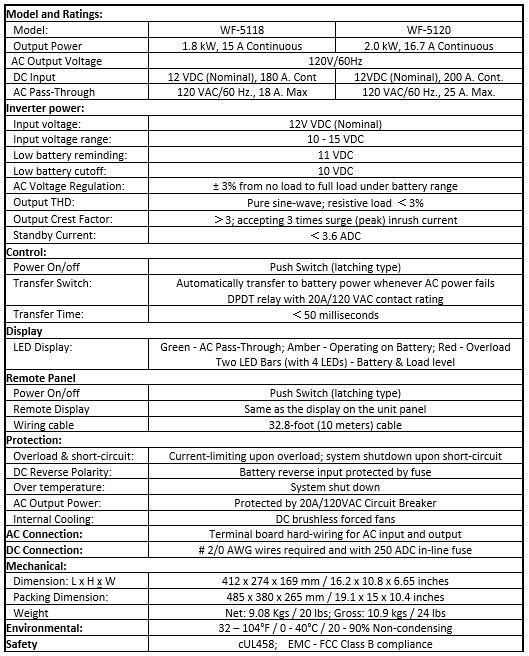
16 SPECIFICATIONS 16 16
17 CONSUMER LIMITED WARRANTY for WFCO Electronic Products WFCO extends, to the original owner, a Two Year Limited Product Warranty. This warranty is in effect from the date of original purchase for a period of two (2) years. This limited warranty is extended specifically for and is limited to Recreational Vehicle application and is only valid within the continental United States, Alaska, Hawaii and the Provinces of Canada. WFCO warrants, to the owner, that its products are free from defects in material and workmanship under normal use and service based on its intended use and function. This warranty is limited to the repair or replacement, at WFCO s discretion, of any defective parts or defective assembly. Any implied warranties of merchantability or fitness for intended use are limited in duration unless applicable State Law provides otherwise. You may have other rights as specified by each individual state. EXCLUSIONS and LIMITATIONS The OEM warranty specifically does not apply to the following: Any WFCO product that has been repaired or altered by an unauthorized person; Any damage caused by misuse, faulty installation, testing, negligence, accident or any WFCO product installed in a commercial vehicle; Any WFCO product, whose serial number has been defaced, altered or removed; Any WFCO product, whose installation has not been in accordance to the WFCO written instructions; Any consequential damages arising from the loss of use of the product including but not limited to: inconvenience, loss of service, loss of revenue, loss or damage to personal property, cost of all services performed in removing or replacing the WFCO product. Specifications are subject to change without notice or obligation. Any WFCO Electronics products sold through unauthorized Internet sources (Example: ebay) will be excluded from all warranty coverage offered by Arterra Distribution / WFCO. 17
18 CONSUMER WARRANTY CLAIM PROCEDURE Upon determination and validation by an authorized OEM dealer that a WFCO product has a defect, a Return Goods Authorization (RGA) number will be required before the product can be returned. The RGA number can be requested by completing the Warranty Information Fax Sheet and appropriate Troubleshooting Form found at com. Once these forms have been completed, the forms along with Proof of Purchase to warranty@wfcoelectronics.com or fax the three documents to the Warranty Department at (574) After receipt of the forms, an RGA number will be issued. This number shall appear on all correspondence with warranty service. Upon validation of the warranty, WFCO shall replace the product with a like product. The RGA number shall be placed on the outside of the carton used to return the product for ease of identification. Do not mark directly on the product. The product must be packaged properly to avoid further product damage which could cause a non-warrantable condition. WARRANTY ASSISTANCE The consumer may contact the selling Dealer or OEM for warranty assistance. The consumer may also contact Arterra Distribution, at: (574) or Fax (574)
19 DIMENSIONAL DRAWING 19
20 20 WFCOELECTRONICS.COM
WF-5110R True Sine Wave Inverter
 Operator s Manual WF-5110R True Sine Wave Inverter WF-9900 Series WF-5110R ( The Inverter model number is located on the label on top of the enclosure) Distributed in the U.S.A. and Canada by ARTERRA DISTRIBUTION
WF-5110R True Sine Wave Inverter
 Operator s Manual WF-5110R True Sine Wave Inverter WF-9900 Series WF-5110R ( The Inverter model number is located on the label on top of the enclosure) Distributed in the U.S.A. and Canada by ARTERRA DISTRIBUTION
Operator Manual For use with WFCO ULTRA III Deckmount Converter WF-9800 Series (model number located on the cover of the unit)
") Operator Manual For use with WFCO ULTRA III Deckmount Converter WF-9800 Series (model number located on the cover of the unit) Distributed in the U.S.A. and Canada by ARTERRA DISTRIBUTION Warranty Service
Operator Manual For use with WFCO ULTRA III Deckmount Converter WF-9800 Series (model number located on the cover of the unit) Distributed in the U.S.A. and Canada by ARTERRA DISTRIBUTION Warranty Service
Operator Manual For use with WFCO ULTRA III Power Center WF-9900 Series (model number located on the door assembly label)
") Operator Manual For use with WFCO ULTRA III Power Center WF-9900 Series (model number located on the door assembly label) Distributed in the U.S.A. and Canada by ARTERRA Distribution Warranty Service (877)
Operator Manual For use with WFCO ULTRA III Power Center WF-9900 Series (model number located on the door assembly label) Distributed in the U.S.A. and Canada by ARTERRA Distribution Warranty Service (877)
Operator Manual For use with WFCO ULTRA III Distribution Center WF-8900 Series (model number located on the door assembly label)
") Operator Manual For use with WFCO ULTRA III Distribution Center WF-8900 Series (model number located on the door assembly label) Distributed in the U.S.A. and Canada by ARTERRA DISTRIBUTION Warranty Service
Operator Manual For use with WFCO ULTRA III Distribution Center WF-8900 Series (model number located on the door assembly label) Distributed in the U.S.A. and Canada by ARTERRA DISTRIBUTION Warranty Service
1000 Watt Pure Sine Wave Power Inverter, Users Manual
 WF-5100 Series 1000 Watt Pure Sine Wave Power Inverter, Users Manual Distributed in the USA and Canada by Arterra Distribution 2021 Aeroplex Drive North. Elkhart, IN. 46514 Phone: 877-294-8997, Fax: 547-294-8698
WF-9500 Series Power Centers
 Operator s Manual WF-9500 Series Power Centers WF-9900 Series WF-9540 WF-9560 WF-9580 ( The Power Center model number is located on the door assembly label ) Distributed in the U.S.A. and Canada by ARTERRA
WF-8500 Series Power Centers
 Operator s Manual WF-8500 Series Power Centers WF-9900 Series WF-8540 WF-8550 WF-8560 ( The Power Center model number is located on the door assembly label ) Distributed in the U.S.A. and Canada by ARTERRA
Operator Manual For use with WFCO ULTRA III Power Center Model WF-8712P and WF-8725P
 Operator Manual For use with WFCO ULTRA III Power Center Model WF-8712P and WF-8725P Distributed in the U.S.A. and Canada by Arterra Distribution Sales (574) 294-8997 Warranty Service (877) 294-8997 Fax
WARNINGS, CAUTIONS AND NOTES
 Welcome Please read this manual thoroughly before installing and operating your new Power Bright Power Inverter. This manual contains information you need to obtain the performance required for your application.
IV. PROOF OF PURCHASE: A warranty claim must be accompanied by proof of the date of purchase.
 PD9100 / 9200 SERIES POWER CONVERTER OWNERS MANUAL PROGRESSIVE DYNAMICS, INC. POWER CONVERTER LIMITED WARRANTY I. LIMITED WARRANTY: Progressive Dynamics, Inc. warrants its power converter to be free from
Go Power! Manual. GP-1750HD Inverter GP-2500 Inverter
 Go Power! Manual GP-1750HD Inverter GP-2500 Inverter Go Power! Electric Inc. PO Box 6033 Victoria, BC V8P 5L4 Tel: 866-247-6527 Fax: 866-607-6527 Email: info@gpelectric.com Table of Contents 1. INTRODUCTION...
The Power of Reliability INSTRUCTION MANUAL
 The Power of Reliability INSTRUCTION MANUAL SAFETY & WARNINGS Read this manual carefully and understand all Warnings and Cautions before connections are made to the Inverter. If unsure about any aspects
GP-1000 Inverter. Go Power! Electric Inc. PO Box 6033 Victoria, BC V8P 5L4 Tel: Fax:
 Go Power! Manual GP-1000 Inverter Go Power! Electric Inc. PO Box 6033 Victoria, BC V8P 5L4 Tel: 866-247-6527 Fax: 866-607-6527 Email: info@gpelectric.com Table of Contents 1. INTRODUCTION 3 2. SPECIFICATIONS
S150,S300 Series Pure Sine Wave Inverter User s Manual
 S150,S300 Series Pure Sine Wave Inverter User s Manual List of contents 1. Important Safety Instructions 3 1-1 General Safety Precautions 3 1-2 Precautions When Working With Batteries.. 3 2. Features...
ADI-125/750 ADI-125/1500 ADI-125/2500
 Manufacturer of Dimensions TM Inverters 4467 White Bear Parkway St. Paul, MN 55110 Phone: 651-653-7000 Fax: 651-653-7600 E-mail: inverterinfo@sensata.com Web: www.dimensions.sensata.com 121094B OWNERS
OWNERS MANUAL JANUARY 2007 ISO
 Manufacturer of Dimensions TM Inverters 4467 White Bear Parkway St. Paul, MN 55110 Phone: 651-653-7000 Fax: 651-653-7600 E-mail: inverterinfo@sensata.com Web: www.dimensions.sensata.com 121231B OWNERS
Power InverterTM Watt. Continuous. User's Manual. WAGAN Corp. Limited Warranty Registration Form. Item no
 WAGAN Corp. Limited Warranty Registration Form All WAGAN Corporation products are warranted to the original purchaser of this product. Warranty Duration: This product is warranted to the original purchaser
DC to AC Power Inverters
 Manufacturer of Dimensions TM Inverters 4467 White Bear Parkway St. Paul, MN 55110 Phone: 651-653-7000 Fax: 651-653-7600 E-mail: inverterinfo@sensata.com Web: www.dimensions.sensata.com ISO 9001:2000 Certified
Table of Contents 文管中心 發行章
 ST600-XXX Series Pure Sine Wave Power Inverter User s Manual Table of Contents 1. Important Safety Instructions 1-1 General Safety Precautions 1 1-2 Battery Precautions. 1 2. Basic Descriptions 2-1 Mechanical
DC to AC Power Inverters
 Manufacturer of Dimensions TM Inverters 4467 White Bear Parkway St. Paul, MN 55110 Phone: 651-653-7000 Fax: 651-653-7600 E-mail: inverterinfo@sensata.com Web: www.dimensions.sensata.com 121114C OWNERS
Dimensions 12/800N 12/1200N D. DC to AC Power Inverters. OWNERS MANUAL for Models: OWNERS MANUAL April ISO 9001:2000 Certified Company
 Manufacturer of Dimensions Inverters 4467 White Bear Parkway St. Paul, MN 55110 Phone: 651-653-7000 Fax: 651-653-7600 E-mail: inverterinfo@sensata.com Web: www.dimensions.sensata.com OWNERS MANUAL April
Pure Sine Wave Inverter GP-HS1500. Owner s Manual
 Pure Sine Wave Inverter GP-HS1500 Owner s Manual 2 Table of Contents Introduction 3 Specifications 4 Name and Main Function 5 Installation 7 Operation 9 Operating Limits 13 Troubleshooting 13 Maintenance
24/3000H-3PH 24/4500H-3PH 24/6000H-3PH
 Manufacturer of Dimensions TM Inverters 4467 White Bear Parkway St. Paul, MN 55110 Phone: 651-653-7000 Fax: 651-653-7600 E-mail: inverterinfo@sensata.com Web: www.dimensions.sensata.com 120015D OWNERS
Cruising Charger Series OWNER S MANUAL
 R Cruising Charger Series OWNER S MANUAL ON BOARD BATTERY CHARGERS Models DC Amperage No. Of Banks Volts 2614A 5,10 Amps 2 Bank 12/12 2614A-230 2621A 5,5,10 Amps 3 Banks 12/12/12 2621A-230 2622A 10,10
Installation and Operation Guide for PD5200 and PD5300 Automatic Transfer Switch
 Installation and Operation Guide for PD5200 and PD5300 Automatic Transfer Switch PD5200 SERIES PD5300 SERIES Member Progressive Dynamics, Inc. 507 Industrial Rd Marshall, MI 49068 www.progressivedyn.com
MIL-24/2600Q MIL-24/3200DQ
 Manufacturer of Dimensions TM Inverters 4467 White Bear Parkway St. Paul, MN 55110 Phone: 651-653-7000 Fax: 651-653-7600 E-mail: inverterinfo@sensata.com Web: www.dimensions.sensata.com 121473B OWNER'S
Installation and Operation Guide for PD4100 Series Power Control Centers
 Installation and Operation Guide for PD4100 Series Power Control Centers Extended warranties are available for purchase at www.progressivedyn.com Member Thank you for selecting Progressive Dynamics as
Go Power! Manual. GP-SW1500 Inverter. Table of Contents. Go Power! Electric Inc. PO Box 6033 Victoria, BC V8P 5L4
 Table of Contents 1. INTRODUCTION... 3 Go Power! Manual GP-SW1500 Inverter 2. SPECIFICATIONS... 3 3. NAME AND MAIN FUNCTION... 3 4. INSTALLATION... 5 5. OPERATION... 7 6. OPERATING LIMITS... 9 7. TROUBLESHOOTING...
Nature Power Inverters. True Sinewave Inverter Modified Sinewave Inverter. Owner s Manual
 Version 1.1 Version 2 Nature Power Inverters True Sinewave Inverter Modified Sinewave Inverter Owner s Manual!!!!!!!!!!! 38304 38204 For safe and optimum performance, the Power Inverter must be used properly.
BRAVO Inverter/Battery Charger. Table of Contents
 BRAVO 1050 Inverter/Battery Charger Table of Contents Introduction... 2 General Description... 2 Specifications... 3 Installation: Hardwire Units... 4 Operation: Hardwire Units... 5-6 Installation: GFCI
Nature Power Inverters. Modified Sinewave 1000w/1500w True Sinewave 1000w/2000w. Owner s Manual
 V1.1 Nature Power Inverters Modified Sinewave 1000w/1500w True Sinewave 1000w/2000w Owner s Manual Modified Sinewave Series True Sinewave Series For safe and optimum performance, the Power Inverter must
OWNERS MANUAL JANUARY 2007 ISO
 Manufacturer of Dimensions TM Inverters 4467 White Bear Parkway St. Paul, MN 55110 Phone: 651-653-7000 Fax: 651-653-7600 E-mail: inverterinfo@sensata.com Web: www.dimensions.sensata.com OWNERS MANUAL JANUARY
O W N E R ' S M A N U A L
 1500 Watt DC to AC Power Inverter C o n v e r t s 1 2 V D C B a t t e r y P o w e r t o 1 1 0 V A C H o m e P o w e r O W N E R ' S M A N U A L SAVE THESE INSTRUCTIONS The recommended source of power is
installation kit Ask your retailer!
 Owner s guide: HD1224 / HD1824 / HD2524 HDI1824 / HDI3024 Install using Tundra CM Series installation kit Ask your retailer! www.tundrainternational.com Table of contents 1 INTRODUCTION... 3 1.1 Disclaimer...
DC-AC Power Inverter SAM Manual. Please read this manual before installing your inverter
 DC-AC Power Inverter SAM-100-12 Owner's Manual Please read this manual before installing your inverter WARNINGS TO REDUCE THE RISK OF FIRE, ELECTRIC SHOCK, EXPLOSION OR INJURY 1. Do not connect to AC distribution
V 2.0 DC TO AC POWER INVERTER PWRINV500012W PWRINV500024W PWRINV500036W PWRINV500048W. Instruction Manual
 DC TO AC POWER INVERTER PWRINV500012W PWRINV500024W PWRINV500036W PWRINV500048W Instruction Manual Introduction The AIMS Power 5000 Watt series inverters are the most advanced line of mobile DC to AC power
PureSine 150/300 Pure Sine Wave Inverter User s Manual
 PureSine 150/300 Pure Sine Wave Inverter User s Manual 1. Important Safety Instructions WARNING! Before you install and use your Inverter, please read and follow these safety instructions. 1-1. General
Installation and Operation Guide. Tundra HD 2500 Power Inverter. for the. Webasto BlueCool Truck System
 Installation and Operation Guide Tundra HD 2500 Power Inverter for the Webasto BlueCool Truck System www.tundrainternational.com www.techwebasto.com BCTSP0063A Table of Contents 1. Introduction 4 1.1 Disclaimer.................................................................................
DC AC POWER INVERTER. LIV 10 / LIV 20 / LIV 30 User Manual
 DC AC POWER INVERTER LIV 10 / LIV 20 / LIV 30 User Manual Save This Manual Please read this manual carefully prior to storage, installation, wiring, operation and maintenance of the Power Inverter. This
Battery Power Inverters
 Battery Power Inverters Renogy 500W 1000W 2000W Pure Sine Wave Inverter Manual 2775 E. Philadelphia St., Ontario, CA 91761 1-800-330-8678 1 Version 1.4 Important Safety Instructions Please save these instructions.
CUL INVERTER/CHARGER OWNER'S MANUAL
 Table of Contents Section 1 Introduction...1 Section 2 Installing the 20-1050CUL... 4 Section 3 Installing the IFM1 Interface Module...6 Section 4-- Installing the Inverter & Charger Remote Panels... 8
MASTERsine Inverter PXA Series Installation Guide
 Backup Power System Expert TM MASTERsine Inverter PXA Series Installation Guide Important Safety Instructions IMPORTANT: Read and save this Installation Guide for future reference. This chapter contains
Operating Instructions for Your Cobra 300 Watt POWER INVERTER M ODEL CPI 300. Nothing comes close to a Cobra
 Operating Instructions for Your Cobra 300 Watt POWER INVERTER M ODEL CPI 300 Nothing comes close to a Cobra 00 300 Watt POWER INVERTER MODEL CPI 300 Congratulations Thank you for purchasing the CPI 300
DC TO AC POWER INVERTER PWRIC150012W INSTRUCTION MANUAL
 DC TO AC POWER INVERTER PWRIC150012W INSTRUCTION MANUAL SAVE THIS MANUAL You will need the manual for the safety warnings and precautions, assembly instructions, operating and maintenance procedures, parts
EN120 EN180. Owner's Guide Conforms to / Conforme à UL std. 458, Toll Free
 WARNING: This Unit employs Components that tend to produce arcs or sparks To prevent fire or explosion, do not install in compartments containing batteries or flammable materials - SHOCK HAZARD. DO NOT
Installation and Operation Guide for PD5100 Automatic Transfer Switch
 Installation and Operation Guide for PD5100 Automatic Transfer Switch Member Progressive Dynamics, Inc. 507 Industrial Rd Marshall, MI 49068 www.progressivedyn.com 2015 Progressive Dynamics, Inc. All rights
Power Inverter 400 MW Owner s Manual
 Power Inverter 400 MW 1204 Owner s Manual For safe and optimum performance, the Power Inverter must be used properly. Carefully read and follow all instructions and guidelines in this manual and give special
VLT SERIES. True Sine Wave AC Power Inverter. Owner s Manual. Owner s Manual D Rev.B
 Owner s Manual VLT SERIES True Sine Wave AC Power Inverter 60Hz Models VLT12-600 VLT12-1000 VLT12-1500 VLT24-600 VLT24-1000 VLT24-1500 VLT48-1000 VLT48-1500 50Hz Models VLTE12-600 VLTE12-1000 VLTE12-1500
IQS300 Series Quasi-Sine Inverter. Installation & Operation Manual
 IQS300 Series Quasi-Sine Inverter Installation & Operation Manual INTRODUCTION State of the Art MOSFET technology coupled with unique Soft-Start circuitry guarantees reliable operation. The ON-OFF switch
230VAC Power Inverter 400W Owner s Manual
 400W 230VAC Power Inverter 400W Owner s Manual For safe and optimum performance, the Enerdrive epower Inverter must be used properly. Carefully read and follow all instructions and guidelines in this manual
Power. On Your Terms.
 Power. On Your Terms. 10 YEAR LIMITED WARRANTY PHI 1310 TM 1 SIMPLIPHI POWER, INC. REV102016 10 YEAR LIMITED WARRANTY: PHI 1310 TM LIMITED PRO-RATED WARRANTY COVERAGE The SimpliPhi Power PHI 1310 as supplied
VP-4124/VP-4124-E 24/48 VOLT DC SWITCHING POWER SUPPLY
 Issue 5 24/48 VOLT DC SWITCHING POWER SUPPLY INTRODUCTION These instructions provide the specifications, installation and maintenance information for the VP-4124 and VP-4124-E, 24/48 Volt Power Supplies.
10 AMP ON BOARD BATTERY CHARGER
 R A Valley Forge Company MODEL 2611A-1-B 10 AMP ON BOARD BATTERY CHARGER One Output OWNER S MANUAL IMPORTANT! READ THESE INSTRUCTIONS BEFORE INSTALLING AND USING THIS PRODUCT. Keep these instructions for
DC TO AC PURE SINE POWER INVERTER PWRI18012S INSTRUCTION MANUAL
 DC TO AC PURE SINE POWER INVERTER PWRI18012S INSTRUCTION MANUAL 1 A. INTRODUCTION The AIMS Power pure sine inverter product line is used for back-up power. The pure sine product line is ideal for sensitive
DX100. Owner's Guide Conforms to UL Std Toll Free
 WARNING: This Unit employs Components that tend to produce arcs or sparks To prevent fire or explosion, do not install in compartments containing batteries or flammable materials- SHOCK HAZARD. DO NOT
Table of Contents. Introduction. How Your Cobra Power Inverter Works. Rechargeable Appliances 1. Quick Checkout 2-3. Operation 4
 Table of Contents Introduction A1 1 2 3 4 5 5 6 7 8 9 10 How Your Cobra Power Inverter Works A3 Rechargeable Appliances 1 Quick Checkout 2-3 Operation 4 Controls and Indicators 5 Operating Limits 6 Input
Pure Sine Wave Inverter Charger
 Pure Sine Wave Inverter Charger Renogy 1000W 2000W Pure Sine Wave Inverter Charger Manual 2775 E. Philadelphia St., Ontario, CA 91761 1-800-330-8678 Version 1.6 1 Important Safety Instructions Please save
PSX-240 Enclosed Autotransformer Installation Manual
 PSX-240 Enclosed Autotransformer Installation Manual IMPORTANT SAFETY INSTRUCTIONS SAVE THESE INSTRUCTIONS! This manual contains important instructions for the OutBack PSX-240 Autotransformer. All of the
WARNING: CAUTION: Notice : XR175 Owner's Guide
 WARNING: This Unit employs Components that tend to produce arcs or sparks To prevent fire or explosion, do not install in compartments containing batteries or flammable materials - SHOCK HAZARD. DO NOT
Pure Sine Wave Inverter User Manual
 48-3000RM 2U 19, 2 Post Rack Mount & 4 Post Open Frame Cabinet Mount Pure Sine Wave Inverter User Manual Newmar PO Box 1306 Newport Beach, CA 92663 www.poweringthenetwork.com Tel: 714-751-0488 M-483000RM
MODEL 2602A-12 3 STAGE AUTOMATIC BATTERY CHARGER OWNER S MANUAL SAVE THESE INSTRUCTIONS
 R A Valley Forge Company MODEL 2602A-12 3 STAGE AUTOMATIC BATTERY CHARGER OWNER S MANUAL SAVE THESE INSTRUCTIONS 1. INTRODUCING THE CHARGER The 2602A-12 is a 3-stage electronic battery charger. Rainproof,
Intelligent Charging System Series
 R Intelligent Charging System Series OWNER S MANUAL ON BOARD BATTERY CHARGERS Models Amperage No. Of Banks Volts 16061 s 1 Bank 12 16102 6,s 2 Banks 12 or 24 16153 6,6,s 3 Banks 12 or 24 or 36 16202 10,10
VP-6124/VP-6124-E 24 VOLT DC SWITCHING POWER SUPPLY
 Issue 6 VP-6124/VP-6124-E 24 VOLT DC SWITCHING POWER SUPPLY INTRODUCTION These instructions provide the specifications, installation and maintenance information for the VP-6124 and VP-6124-E, 24Volt Power
3000W Pure Sine Inverter (38330) Owner s Manual
 Owner s Manual") 3000W Pure Sine Inverter (38330) Owner s Manual For safe and optimum performance, the Nature Power 3000W Pure Sine Inverter must be used properly. Carefully read and follow all instructions and guidelines
3000W Pure Sine Inverter (38330) Owner s Manual For safe and optimum performance, the Nature Power 3000W Pure Sine Inverter must be used properly. Carefully read and follow all instructions and guidelines
ITS-50R TRANSFER SWITCH OWNER S MANUAL
 ITS-50R OWNER S MANUAL IOTA Engineering Transfer Switches provide automatic power switching between two or three separate 120/240 volt AC input sources, including powercords, onboard generators, onboard
SAVE THESE INSTRUCTIONS
 R MODEL 2611 10 AMP ON BOARD BATTERY CHARGER Two Outputs OWNER S MANUAL Connections at a glance: For the best charging results both 12 Volt independent batteries should be equally discharged. The charger
Toll Free DX100. Owner's Guide. Printed in China
 Toll Free 1 866 295 6775 www.powerbright.com DX100 Owner's Guide Printed in China 1 Introduction Thank you for purchasing thepowerbright DX100. Connected to the 12 volt outlet in your vehicle, the DX100
INSTRUCTIONS FOR OUTDOOR WALL LANTERN, MODEL LPT-1107
 INSTRUCTIONS FOR OUTDOOR WALL LANTERN, MODEL LPT-1107 Page 1 Thank you for purchasing this Langport Lighting outdoor wall lantern. This product has been manufactured with the highest standards of safety
10 Year Limited Warranty
 Power. On Your Terms. 10 Year Limited Warranty PHI 2.7 TM PHI 3.5 TM 60A SIMPLIPHI POWER, INC. REV020618 10 Year Limited Warranty: PHI 2.7 TM PHI 3.5 TM 60A 24V 48V Limited Pro-Rated Warranty Coverage
1200+ WITH LVD (LOW VOLTAGE DISCONNECT) USER GUIDE
 USER GUIDE") 1200+ WITH LVD (LOW VOLTAGE DISCONNECT) USER GUIDE INST045 Doc 2.00 CONTENTS General Information...2 Operating Environment...6 Features...7 Installation Instructions...8 Inverter Ground and Remote Sense
1200+ WITH LVD (LOW VOLTAGE DISCONNECT) USER GUIDE INST045 Doc 2.00 CONTENTS General Information...2 Operating Environment...6 Features...7 Installation Instructions...8 Inverter Ground and Remote Sense
Table of Contents. Introduction. How Your Cobra Power Inverter Works. Rechargeable Appliances 1. Quick Checkout 2-3. Operation 4
 Table of Contents Introduction A1 1 2 3 4 5 5 6 7 8 9 10 How Your Cobra Power Inverter Works A3 Rechargeable Appliances 1 Quick Checkout 2-3 Operation 4 Controls and Indicators 5 Operating Limits 6 Input
S600,S600R Series Pure Sine Wave Inverter User s Manual
 S600,S600R Series Pure Sine Wave Inverter User s Manual List of contents 1. Important Safety Instructions 1 1-1 General Safety Precautions 1 1-2 Precautions When Working With Batteries.. 1 2. Features...
GSL Electronics Modified Sine Wave Power Inverters
 GSL Electronics Modified Sine Wave Power Inverters Congratulations on choosing one of our Modified Sine Wave Inverters for your application. There are 6 models in the range, which will meet most of your
Product Overview. Product Identification. Amps One CT Two CTs Three CTs
 AH06 (optional mounting bracket for small, medium, and large CTs) DANGER HAZARD OF ELECTRIC SHOCK, EXPLOSION, OR ARC FLASH Follow safe electrical work practices. See NFPA 70E in the USA, or applicable
Transfer Switch TS-50. Owner s Manual
 Transfer Switch TS-50 Owner s Manual Table of Contents Introduction 2 Installation 2 Operational Testing 7 Troubleshooting 7 Hi-Pot Testing 8 Generator Note 9 Medical Appliances 10 Caution 10 Disclaimer
HG PI2000. How Your HG PI2000 Power Inverter Works Watt Power Inverter. Nothing comes close to a Cobra TM
 Operating Instructions for Your HighGear by Cobra 2000 Watt Power Inverter HG PI2000 How Your HG PI2000 Power Inverter Works How Your Cobra Power Inverter Works The Cobra Power Inverter is an electronic
Installing Power Components
 This chapter provides instructions on how to install and reinstall power components in the Cisco NCS 4016 chassis. It also covers connecting and disconnecting power and powering on the chassis. The Cisco
REDI-LINE. Rugged, Reliable, DC to AC Power Conversion ELECTRIC GENERATORS USER'S GUIDE. KARAM A.L.
 REDI-LINE ELECTRIC GENERATORS USER'S GUIDE Rugged, Reliable, DC to AC Power Conversion KARAM A.L. www.alternatorstarter.com 1-888-515-2726 REDI-LINE ELECTRIC GENERATOR MODEL INPUT ACTUAL OUTPUT ACTUAL
DC to AC Power Inverter Pure Sine Wave Output. Owner s Manual. Models: 12LP10 12LP10H 12LP10R
 DC to AC Power Inverter Pure Sine Wave Output Owner s Manual Models: 12LP10 12LP10H 12LP10R INTRODUCTION Thank you for purchasing a Magnum-Dimensions Inverter from Sensata Technologies! We think that you
OWNER S MANUAL AND INSTALLATION INSTRUCTIONS
 EmerGen Switch Manual Transfer Switch OWNER S MANUAL AND INSTALLATION INSTRUCTIONS For A Series Models 6-5001, 6-7501, 10-7501, 10-12K1 PLEASE READ THIS MANUAL IN ITS ENTIRETY BEFORE INSTALLING AND/OR
Installation & Operation Instructions. Deluxe LED Spot Light
 Installation & Operation Instructions Deluxe LED Spot Light 405626-3 To avoid the risk of accidents or damage to this product, it is essential to read these instructions thoroughly SDG Edition before this
Pure Sine Wave Inverter 600W-24V User Manual
 Pure Sine Wave Inverter 600W-24V User Manual Manual Version:INV-600W-2016-1 Table of Contents 1. INTRODUCTION... 1 1.1 General Description... 1 1.2 Key Features... 2 2. SAFETY INSTRUCTIONS... 2 2.1 Installation
HPP1 MK5 Owner s Manual
 J Wolmarans Page 1 2017/03/07 Page 1 of 10 TABLE OF CONTENTS Page 1 Introduction...2 2 Models...2 3 Safety warnings...3 4 Features...3 5 Contents...3 6 Installation...3 6.1 Mounting the unit:...3 6.2 Connecting
Matson Jump Starter Operator s Manual
 Matson Jump Starter Operator s Manual RA3800 SAVE THESE INSTRUCTIONS: This manual contains important safety and operating instructions for the RA3800 Jumpstart. Read through this owner s manual carefully
PURE SINE WAVE DC-AC INVERTERS
 AC POWER SOURCE PURE SINE WAVE DC-AC INVERTERS MODEL: PST-60S-24A OWNER S MANUAL Please read this manual before operating your inverter. INDEX Contents General Safety & Installation... 3 Warning... 4 Description
Operating Instructions
 FUSE 028028 Operating Instructions Monarch 9876 and 9878 Mobile Work Station (MWS ) TC987xOI Rev. AC 12/15 2007 Avery Dennison Corp. All rights reserved. Each product and program carries a respective
RU BMS Power Supply and Battery Management System Owners Guide
 RU2-4012- BMS Power Supply and Battery Management System Owners Guide (These instructions are intended for use by a technician familiar with electronic products) RU2-4012- BMS is a continuous duty power
Smart Battery Charger GPC-35-MAX GPC-45-MAX GPC-55-MAX GPC-75-MAX GPC-100-MAX. Owner s Manual
 Smart Battery Charger GPC-35-MAX GPC-45-MAX GPC-55-MAX GPC-75-MAX GPC-100-MAX Owner s Manual Table of Contents Important Safety Instructions 2 Features 3 Installation Guidelines 5 Warranty 8 1.0 Important
HPP1 MK6-15A/20A R00 Owners Manual
 J Wolmarans Page 1 2018/10/23 Page 1 of 7 TABLE OF CONTENTS Page 1 Introduction...2 2 Model...2 3 Safety warnings...2 4 Contents...2 5 Features...2 6 Installation...3 6.1 Mounting the unit:...3 6.2 Connecting
Inverter User Manual
 Inverter User Manual -------------for standard model DC TO AC Power Inverter CONTENTS Safety First 1. Introduction 2. Installation Guidelines 3. Using the inverter 4. Troubleshooting 5. Specifications
Select II Portable Braking System
 39523 Select II Portable Braking System Inventor and Leader in Portable Technology! INSTRUCTIONS NEED HELP? CALL - 1-800-470-2287 (MONDAY - FRIDAY 8AM - 5PM CST) WARNING Read all instructions before installing
User Guide IGD Series
 US User Guide IGD Series DANGER PRIOR TO USE, READ AND UNDERSTAND PRODUCT SAFETY INFORMATION. Failure to follow the instructions may result in ELECTRICAL SHOCK, EXPLOSION, or FIRE, which may result in
Digital echo-charge. Owner s Manual. Xantrex Digital echo-charge Battery Charger
 Digital echo-charge Owner s Manual Xantrex Digital echo-charge Battery Charger INTRODUCTION The Xantrex Digital echo-charge is specially developed for charging an auxiliary battery with Freedom TM or Fleet
JUMP STARTER OPERATOR S MANUAL RA1900
 JUMP STARTER OPERATOR S MANUAL RA1900 SAVE THESE INSTRUCTIONS: This manual contains important safety and operating instructions for the RA1700 jump start. Read through this owner s manual carefully before
FOR YOUR SAFETY The use of the appropriate Tundra CM Series installation kit is highly recommended
 8 Owner Manual POWER INVERTERS Model: S300 / S600 / S1200 FOR YOUR SAFETY The use of the appropriate Tundra CM Series installation kit is highly recommended www.tundrainternational.com PN. Table of contents
DC TO AC POWER INVERTER PWRINV150W INSTRUCTION MANUAL
 DC TO AC POWER INVERTER PWRINV150W INSTRUCTION MANUAL SAVE THIS MANUAL You will need the manual for the safety warnings and precautions, assembly instructions, operating and maintenance procedures, parts
INSTRUCTION MANUAL. 12-Station HD Shop 12V Portable Battery Charger
 INSTRUCTION MANUAL 12-Station HD Shop 12V Portable Battery Charger IMPORTANT SAFETY INSTRUCTIONS 1. SAVE THESE INSTRUCTIONS This manual contains important safety and operating instructions for your HD
CLASSIC II Portable Braking System
 39495 CLASSIC II Portable Braking System Inventor and Leader in Portable Technology! INSTRUCTIONS NEED HELP? CALL - 1-800-470-2287 (MONDAY - FRIDAY 8AM - 5PM CST) WARNING Read all instructions before installing
Eclipse Plus VA UPS and Surge Suppressor User s Manual
 Eclipse Plus 250 250VA UPS and Surge Suppressor User s Manual Compact UPS/Surge Suppressor for Home Office or Small Office Use www.mgeups.com Notes Contents Thank You!.....................................................