WF-9500 Series Power Centers
|
|
|
- Darrell Black
- 5 years ago
- Views:
Transcription
 294-8997 Warranty: warranty@wfcoelectronics.com Fax (574) 294-8698 www.wfcoelectronics.com Power PROs Technical Support (877) 294-8997")
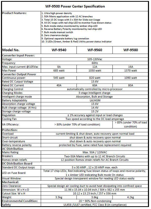
1 Operator s Manual WF-9500 Series Power Centers WF-9900 Series WF-9540 WF-9560 WF-9580 ( The Power Center model number is located on the door assembly label ) Distributed in the U.S.A. and Canada by ARTERRA DISTRIBUTION (877) Warranty: warranty@wfcoelectronics.com Fax (574) Power PROs Technical Support (877)
2 TABLE OF CONTENTS SAFETY INFORMATION... 3 GENERAL INFORMATION Reverse Battery Protection... 3 Blown Fuse Indicators... 4 Automatic Cooling Fan... 4 AC Voltage Indicators... 4 Over-Temperature Protection... 5 Electronic Current Limiting... 5 Short Circuit Protection... 5 CIRCUIT PROTECTION DC Fuses... 5 AC Circuit Breakers... 5 OPERATIONAL FEATURES 3-Stage Smart Charging... 7 Absorption Mode... 7 Bulk Mode... 8 Float Mode... 8 TROUBLESHOOTING INSTRUCTIONS Converter Output Voltage... 9 Reverse Polarity Fuses... 9 Troubleshooting Flow Chart GENERAL COMPLIANCE INFORMATION Agency Listings INSTALLATION INSTRUCTIONS Mounting the Enclosure Wiring the AC Breakers Wiring the DC Fuse Board SPECIFICATIONS WARRANTY INFORMATION
3 !WARNING! Risk of Electrical Shock. Disconnect or isolate all power supplies before making electrical connections. More than one disconnection or isolation may be required to completely de-energize equipment. Contact with components carrying hazardous voltage can cause electric shock and may result in severe personal injury or death.!important! All wiring must conform to local, national, and regional regulations. Use copper conductors only for all wire connections. Do not exceed the electrical ratings for the WF-9500 or the equipment connected to it.!caution! This product should be installed by an experienced technician. CAUTION and care must be taken when servicing this equipment. To prevent severe shock or electrocution, consult your servicing dealer.!warning! This unit employs components that can produce arcs or sparks. To prevent fire or explosion, do not install in compartments containing batteries or flammable materials (LP gas). This product is NOT ignition protected.!caution! To prevent fire, do not cover or obstruct front cover ventilation openings. For continued protection against risk of fire or electric shock, replace faulty DC fuses and AC breakers with ones of the same type and ratings as are installed.!caution! When using a battery with the WF-9500 Series, follow battery maintenance procedures. Check the fluid level in any battery connected to RV charging system on a monthly basis. GENERAL INFORMATION WF-9500 Series Safety Features Reverse Battery Protection The WF-9500 Series Power Centers will charge the 12-volt House battery if installed. A battery does not have to be installed for WF-9500 Series Power Center converter operation. When a battery is installed, two reverse polarity fuses are installed to protect the converter circuitry. The fuses are located along the bottom edge of the DC fuse board near the VCC+ lug (refer to Figure 1 below). This feature prevents permanent damage to the converter from a battery connected into the circuit backwards. Blown polarity fuses are indicated by an illuminated Red LED near the lugs. In addition to protecting the converter section, the reverse polarity fuses are the main connection between the converter and the DC fuse board. 3
4 Blown Fuse Indicators on DC Fuse Board The DC Fuse Board has individual blown fuse indicators as standard equipment. Each of the 17 DC fuse circuits contain a Red LED to indicate a blown fuse. If one of the circuits draws more current than the rating of the fuse, the fuse will blow. When this occurs, the Red LED for that circuit will illuminate. Replace the blown fuse with a known good fuse of the same rating. NOTE: If the replacement fuse blows again, check that circuit for a short or an overload condition. Figure 1 Automatic Cooling Fan The cooling fan in the WF-9500 Series Power Center is incremental and is controlled by the current drawn out of the converter to the applied load. The on-board microprocessor increases fan speed as the total load increases, and decreases fan speed as the load decreases. Unlike traditional temperature-controlled fans, the load-controlled fan provides better component cooling by avoiding temperature spikes which can lead to premature component failure. AC Voltage Input Indicators The WF-9500 Series Power Centers have built-in indication of the incoming AC voltage. Three LEDs give at-a-glance status of Low, Normal or High voltage (see Figure 2 below). If the incoming voltage is within the normal operating range of 105 to 130 VAC, the Green LED will be illuminated. However, if the incoming voltage is less than 105 VAC, the Yellow LED will illuminate. If the incoming voltage is greater than 130 VAC, the Red LED will illuminate. If either the Red or Yellow LED is illuminated, shut down the WF-9500 Series Power Center and investigate the cause of the problem. Figure 2 4
5 Over-Temperature Protection If the internal temperature of the converter exceeds a critical point, it will shut down. This protects the unit from excessive heat that may damage sensitive components. The unit will restart once the temperature inside has dropped. Electronic Current Limiting In the event that the output current exceeds the maximum rating for the WF-9500 Series Power Center, the output current will remain constant but the output voltage will begin to drop. If this occurs, the unit will recover once loads are reduced. Short-Circuit Protection Should a short circuit occur in the RV, the WF-9500 Series Power Center will drop the voltage output to zero volts. If the short-circuit condition is removed and no other fault conditions are detected, the converter will resume normal operation. However, short-circuit conditions are dangerous, and the RV will require inspection by a qualified service technician. CIRCUIT PROTECTION WF-9500 Series Power Center Fuses and Breakers DC Fuses (12 Volts) The DC fuse board has spaces for seventeen (17) DC circuits. This includes three (3) 30 Amp circuits which may be used for any load requiring up to 30 Amps of current draw (Example: Slide-Outs). These three (3) circuits have a maximum rating of 30 Amps. The remaining fourteen (14) circuits have a maximum 20 Amp rating. The circuit fuses and the Reverse Battery Protection fuses should be replaced with ATC or ATO automotive type fuses such as: Littelfuse type 257 Bussmann type ATC AC Circuit Breakers (120/240 Volts) The AC Breaker side of the WF-9500 Series Power Center is located on the upper left side. The WF-9500 Series Power Center accepts standard residential breakers. A total of fourteen (14) breakers can be installed: two (2) 50 Amp Main breaker and up to a maximum of twelve (12) AC Branch circuits when using duplex breakers. A list of factory tested and approved breakers follows. UL-Listed Main Circuit Breakers, rated for 30/50 Amp, 120/240 VAC The following breakers have been factory tested and approved for use as 50 Amp Main breakers in the WF-9500 Series Power Centers: Manufacturer Eaton ITE/Siemens Square D Murray General Electric Model/Cat. No./Type Type BR Type QP or QT Type HOM Type MP or MH Type THQL 5

6 UL-Listed Branch Circuit Breakers, Rated for 120 V, Maximum 20 A The following breakers have been factory tested and approved for use as Branch Breakers in the WF-9500 Series Power Centers: Manufacturer Eaton ITE/Siemens Square D Murray General Electric Model/Cat. No./Type Type BRD Type QP or QT Type HOMT Type MPT or MHT Type THQL When replacing any of the installed circuit breakers, the replacement should be of the same manufacturer, type designation, and equal or greater interrupting rating, not to exceed 50 A. The Short-Circuit-Current rating for the breaker should be 10,000 Amps at 120/240 VAC. Breaker Filler Plates: Model FP-01 or FP-01B (Black) Figure 3 6

7 OPERATIONAL FEATURES Converter Operation Modes Three-Stage Smart Charging In order to maximize battery life, it is best to charge batteries slowly, keeping them topped off with a trickle-charge when the RV is not being used. The Three-Stage smart charger continuously measures the battery voltage output and regulates the amount of charge using three modes of operation: Absorption, Bulk and Float modes. Converter Modes of Operation Understanding output voltages of a three stage converter Figure 4 All WFCO power converters are automatic three-stage switching power supplies. The converter senses which mode it needs to be in by checking the RV system voltage. Absorption Mode This is the default or normal mode of operation. This mode provides an output of 13.6 VDC to the DC circuits in the RV. Because RVs today are designed with converters sized to provide ample DC output power for all DC loads in normal usage, an RV will rarely require anything other than Absorption Mode. When a WF-9500 Power Center is connected to a battery and is operating in Absorption Mode, it is constantly charging that battery any time the converter output is greater than the voltage level of the battery. If the battery is at or near fully charged, the current draw from the converter to the battery may be very small. If the battery were to be fully discharged, the current draw from the converter to the battery may be quite high. The WF-9500 Series Power Center can charge most properly-functioning, fully-discharged batteries (measured at 11.9 VDC) to a fully-charged level of 12.7 VDC in less than three hours when the converter output is in Absorption Mode (13.6 VDC) and a 20 Amp lighting load is connected. Please note that adding more DC loads to the circuits will decrease the amount of current available to charge the battery, and thus will increase the time required for the battery to reach a full charge. Batteries with damaged cells or sulfation will also require additional time to charge, and may never reach a full charge voltage. 7
8 Because of the relationship between voltage and amperage, once the converter reaches its maximum rated operating current level, any increase in the DC load will start to decrease the voltage output level. The converter will go into Bulk Mode when the measured output from the converter reaches approximately 12.5 VDC. Bulk Mode This mode is designed to charge a significantly discharged battery in a little less time than Absorption Mode. The microprocessor in WF-9500 Power Center continuously monitors the DC output voltage. When the microprocessor senses that the output voltage has dropped to a preset level, it will boost the output voltage from 13.6 VDC to approximately 14.4 VDC. The increased voltage will help the battery charge a little faster, while still providing power to the DC lighting and appliances in the RV. In Bulk Mode, it may not be possible to observe the 14.4 VDC output because of the voltagecurrent relationship. To measure the 14.4 VDC output with a voltmeter, reduce some DC loads while monitoring the voltage at the converter output. As the DC loads are removed, the voltage will begin to climb until 14.4 VDC (nominal) is shown on the meter. As the battery continues to charge, the current drawn by the battery will gradually decrease. WFCO Converters are designed to drop out of Bulk Mode when the total amperage draw from the converter reaches a preset point, indicating the battery is charged. If the amperage draw stays above the preset point, the converter will stay in Bulk Mode for a maximum of four hours. These features have been implemented to protect and extend the life of the battery. Float Mode This mode is the third stage of converter operation. It is designed to provide a trickle charge to the battery. If the converter observes no significant variations in current draw for approximately 44 continuous hours, it will drop the output of the converter from 13.6 VDC to 13.2 VDC. This lower voltage will keep the battery charged while the RV is not in use. This also helps preserve the life of the battery, while keeping it charged and ready for use. A small change in DC current, such as turning on a light or DC appliance, will cause the converter to exit Float Mode and return to the Absorption Mode. Note: While in the float mode, the converter will continue to supply a trickle charge to the battery. If the RV is in storage for thirty (30) days or more, it is good practice to check the battery and its fluid levels on a monthly basis. NOTE: for a detailed explanation of the charging modes, please refer to our publication Theory of Operation, located under the Support heading on 8
9 TROUBLESHOOTING INSTRUCTIONS Troubleshooting the WF-9500 Series Power Center Refer to the Troubleshooting Guide for the WF-9500 Series Power Center (Figure 5) on the next page. Converter Output Voltage Before checking the WF-9500 Series Power Center output voltage, disconnect the battery cables at the battery. Make sure the converter is plugged into an AC source ( Volts). Check the converter output voltage at the battery with a voltmeter. Place the meter probes on the disconnected battery cables; place the Positive (red) meter probe on the + Positive red battery wire and place the Negative (black) meter probe on the Negative black wire on the battery cable. Be sure you have good connections at the cables. If the voltage reads 13.6 VDC (+/- 0.2) with no load, the converter is functioning properly. If the converter output voltage at the battery reads 0.0 VDC, or if the battery is not charging, check for an open inline fuse in the battery wire circuit. One may have been installed by the RV manufacturer. Also check for loose wiring connections. Reverse-Polarity Fuses If there is no DC output coming from the WF-9500 Series Power Center converter section, first check the reverse polarity fuses on the fuse board. Then, visually inspect the fuses for any breaks in the fuse element. If no breaks are found, use a continuity tester to check for continuity. If the reverse polarity fuses are blown, it means the RV battery was accidentally connected in reverse, either at the battery or at the converter. Investigate the connections and reconnect the cables properly. Replace the fuse with the same type and amperage rating as the original. IMPORTANT: These fuses protect the converter from damage in the event that the RV battery is accidentally connected in reverse. A reversed battery connection, even if for only a second, will cause these fuses to blow. If the above checks have been made but the converter output still reads 0.0 VDC, the converter is not functioning properly. Contact the Arterra Distribution Power PROs at 1 (877)
10 Troubleshooting Guide for WF-9500 Series Power Center Figure 5 10
11 GENERAL COMPLIANCE INFORMATION Agency Listings UL The WF-9500 Series Power Centers are UL-Listed, and cul-listed (Canadian). FCC Compliance Class B NOTE: This equipment has been tested and found to comply with the limits for a Class B digital device, pursuant to Part 15 of the FCC Rules. These limits are designed to provide reasonable protection against harmful interference when the equipment is operated in a commercial environment. This equipment generates, uses, and can radiate radio frequency energy, and if not installed and used in accordance with the instruction manual, may cause harmful interference to radio communications. Operation of this equipment in a residential area is likely to cause harmful interference in which case the user will be required to correct the interference at his own expense. INSTALLATION INSTRUCTIONS Installing the WF-9500 Series Power Center Mounting the Enclosure The WF-9500 Series Power Center enclosure should be mounted in an accessible area such as a wall or in the side of a cabinet. The front of the enclosure should not be obstructed to allow free air flow for the cooling fan. The enclosure will slide into a rough opening of (in) H x (in) W. The enclosure depth is (in). After wiring is completed, the enclosure fastens to the wall or cabinet using 4 wood screws, not supplied. Wiring the AC Breakers ** Make sure no AC power is coming into the RV from either the Shore Power cord or an on-board generator. Determine the proper size breakers for the loads the WF-9500 Series will be powering. You can use either single or duplex breakers, or a combination of both. We recommend that all the breakers used be of the same brand. When using duplex style circuit breakers, a total of fourteen (14) breakers can be mounted in the WF-9500 Series Power Center, two (2) Main breakers and twelve (12) Branch breakers. Refer to the tables on pages 5 and 6 for a selection of approved breakers. The Main breaker should be a 2-pole, 50 Amp type and should be installed in the center position (See Figure 6 on page 13). A hold down clip is provided to keep the breaker securely in place. The 50 Amp power cord is routed through the largest knockout in the wiring compartment and secured with a listed strain relief clamp. A 50 Amp power cord has 4 leads; Black (HOT1), Red (HOT2), Neutral (White), and Ground (Green). The Black (HOT1) wire is connected to one side of the 2-pole 50 Amp Main breaker as shown in Figure 6 on page 13. The Red (HOT2) is connected to the other side. The White (Neutral) wire is connected to the Neutral Terminal bar at the bottom left of the wiring compartment. The Green (Ground) wire is connected to the Ground Terminal bar located at the top left of the compartment. 11
12 An 8AWG copper conductor shall be used to bond the WF-9500 Series Power Center to the vehicle frame. Route the Romex leads for the Branch circuits through the Strain Reliefs in the back of the wiring compartment. In a similar fashion, connect the Black wire to the Branch breaker, and the White and Green wires to the appropriate Terminal bar. The Black power wire for the converter has a pigtail connection. The metal pin is inserted in the Branch breaker designated for converter power. The end with the wire nut can be used to power another circuit if necessary. If not used, leave the wire nut installed and push the wire to the side. Make sure all terminals are torqued to the specifications listed on the back of the enclosure. Wiring the DC Fuse Board ** Make sure the house battery is disconnected and there is no AC Power connected to the system before beginning the DC wiring. Determine what DC loads are to be connected to the fuse board and what position they will occupy. The 3 circuits closest to the battery lugs may be used for 30 Amp Max loads, and can accept a maximum 30 Amp ATO or ATC fuses installed. The remaining fourteen circuits are general purpose and can accept up to 20 Amp ATO or ATC fuses installed. Make sure the fuses are seated properly. Depending on the WF-9500 Series Power Center model, there are 3 different methods of connecting the DC loads to the fuse board. -S Models. These models have screw terminal connections. Strip approximately.25 of insulation from the load s wire and insert into the screw terminal. Tighten the terminal to the torque specified on the back of the enclosure. -Q Models. These models have a male Quick Connect tab on the fuse board and mate with a female Quick Connect on the load wire. When installing this terminal, be sure the female terminal is fully seated on the fuse board. -W Models. These models have a 12 wire for each circuit extending from the back of the enclosure. Strip approximately.50 insulation from the load s wire, twist the bare wire from the appropriate fuse position together with the load wire, and securely fasten with a suitably listed connector. Connect the heavy wire (Red) coming from the battery to the BAT+ lug located directly above the VCC lug on the fuse board. Make sure this lug is torqued properly. As a last step, install a separate bus bar in a location behind the converter. Run a 6 AWG wire from the NEG- lug on the bottom left of the DC fuse board to this bus bar. Connect the battery negative wire to this bus bar along with all the negative DC load wires. Also, run a wire from the bus bar to chassis ground. 12

13 Figure 6 13
14 14
15 CONSUMER LIMITED WARRANTY for WFCO Electronic Products WFCO extends, to the original owner, a Two Year Limited Product Warranty. This warranty is in effect from the date of original purchase for a period of two (2) years. This limited warranty is extended specifically for and is limited to Recreational Vehicle application and is only valid within the continental United States, Alaska, Hawaii and the Provinces of Canada. WFCO warrants, to the owner, that its products are free from defects in material and workmanship under normal use and service based on its intended use and function. This warranty is limited to the repair or replacement, at WFCO s discretion, of any defective parts or defective assembly. Any implied warranties of merchantability or fitness for intended use are limited in duration unless applicable State Law provides otherwise. You may have other rights as specified by each individual state. EXCLUSIONS and LIMITATIONS The OEM warranty specifically does not apply to the following: Any WFCO product that has been repaired or altered by an unauthorized person; Any damage caused by misuse, faulty installation, testing, negligence, accident or any WFCO product installed in a commercial vehicle; Any WFCO product, whose serial number has been defaced, altered or removed; Any WFCO product, whose installation has not been in accordance to the WFCO written instructions; Any consequential damages arising from the loss of use of the product including but not limited to: inconvenience, loss of service, loss of revenue, loss or damage to personal property, cost of all services performed in removing or replacing the WFCO product. Specifications are subject to change without notice or obligation. Any WFCO Electronics products sold through unauthorized Internet sources (Example: ebay) will be excluded from all warranty coverage offered by Arterra Distribution / WFCO. CONSUMER WARRANTY CLAIM PROCEDURE Upon determination and validation by an authorized OEM dealer that a WFCO product has a defect, a Return Goods Authorization (RGA) number will be required before the product can be returned. The RGA number can be requested by completing the Warranty Information Fax Sheet and appropriate Troubleshooting Form found at Once these forms have been completed, the forms along with Proof of Purchase to warranty@wfcoelectronics.com or fax the three documents to the Warranty Department at (574) After receipt of the forms, an RGA number will be issued. This number shall appear on all correspondence with warranty service. Upon validation of the warranty, WFCO shall replace the product with a like product. The RGA number shall be placed on the outside of the carton used to return the product for ease of identification. Do not mark directly on the product. The product must be packaged properly to avoid further product damage which could cause a non-warrantable condition. WARRANTY ASSISTANCE The consumer may contact the selling Dealer or OEM for warranty assistance. The consumer may also contact Arterra Distribution at: (574) or Fax (574)
16 WFCOELECTRONICS.COM
WF-8500 Series Power Centers
 Operator s Manual WF-8500 Series Power Centers WF-9900 Series WF-8540 WF-8550 WF-8560 ( The Power Center model number is located on the door assembly label ) Distributed in the U.S.A. and Canada by ARTERRA
Operator Manual For use with WFCO ULTRA III Power Center WF-9900 Series (model number located on the door assembly label)
") Operator Manual For use with WFCO ULTRA III Power Center WF-9900 Series (model number located on the door assembly label) Distributed in the U.S.A. and Canada by ARTERRA Distribution Warranty Service (877)
Operator Manual For use with WFCO ULTRA III Power Center WF-9900 Series (model number located on the door assembly label) Distributed in the U.S.A. and Canada by ARTERRA Distribution Warranty Service (877)
Operator Manual For use with WFCO ULTRA III Distribution Center WF-8900 Series (model number located on the door assembly label)
") Operator Manual For use with WFCO ULTRA III Distribution Center WF-8900 Series (model number located on the door assembly label) Distributed in the U.S.A. and Canada by ARTERRA DISTRIBUTION Warranty Service
Operator Manual For use with WFCO ULTRA III Distribution Center WF-8900 Series (model number located on the door assembly label) Distributed in the U.S.A. and Canada by ARTERRA DISTRIBUTION Warranty Service
Operator Manual For use with WFCO ULTRA III Power Center Model WF-8712P and WF-8725P
 Operator Manual For use with WFCO ULTRA III Power Center Model WF-8712P and WF-8725P Distributed in the U.S.A. and Canada by Arterra Distribution Sales (574) 294-8997 Warranty Service (877) 294-8997 Fax
Operator Manual For use with WFCO ULTRA III Deckmount Converter WF-9800 Series (model number located on the cover of the unit)
") Operator Manual For use with WFCO ULTRA III Deckmount Converter WF-9800 Series (model number located on the cover of the unit) Distributed in the U.S.A. and Canada by ARTERRA DISTRIBUTION Warranty Service
Operator Manual For use with WFCO ULTRA III Deckmount Converter WF-9800 Series (model number located on the cover of the unit) Distributed in the U.S.A. and Canada by ARTERRA DISTRIBUTION Warranty Service
WF-5100 Series True Sine Wave Inverters
 Operator s Manual WF-5100 Series True Sine Wave Inverters WF-9900 Series WF-5118 WF-5120 ( The Inverter model number is located on the label on top of the enclosure) Distributed in the U.S.A. and Canada
WF-5110R True Sine Wave Inverter
 Operator s Manual WF-5110R True Sine Wave Inverter WF-9900 Series WF-5110R ( The Inverter model number is located on the label on top of the enclosure) Distributed in the U.S.A. and Canada by ARTERRA DISTRIBUTION
WF-5110R True Sine Wave Inverter
 Operator s Manual WF-5110R True Sine Wave Inverter WF-9900 Series WF-5110R ( The Inverter model number is located on the label on top of the enclosure) Distributed in the U.S.A. and Canada by ARTERRA DISTRIBUTION
1000 Watt Pure Sine Wave Power Inverter, Users Manual
 WF-5100 Series 1000 Watt Pure Sine Wave Power Inverter, Users Manual Distributed in the USA and Canada by Arterra Distribution 2021 Aeroplex Drive North. Elkhart, IN. 46514 Phone: 877-294-8997, Fax: 547-294-8698
IV. PROOF OF PURCHASE: A warranty claim must be accompanied by proof of the date of purchase.
 PD9100 / 9200 SERIES POWER CONVERTER OWNERS MANUAL PROGRESSIVE DYNAMICS, INC. POWER CONVERTER LIMITED WARRANTY I. LIMITED WARRANTY: Progressive Dynamics, Inc. warrants its power converter to be free from
Installation and Operation Guide for PD4100 Series Power Control Centers
 Installation and Operation Guide for PD4100 Series Power Control Centers Extended warranties are available for purchase at www.progressivedyn.com Member Thank you for selecting Progressive Dynamics as
SAVE THESE INSTRUCTIONS
 R MODEL 2611 10 AMP ON BOARD BATTERY CHARGER Two Outputs OWNER S MANUAL Connections at a glance: For the best charging results both 12 Volt independent batteries should be equally discharged. The charger
Cruising Charger Series OWNER S MANUAL
 R Cruising Charger Series OWNER S MANUAL ON BOARD BATTERY CHARGERS Models DC Amperage No. Of Banks Volts 2614A 5,10 Amps 2 Bank 12/12 2614A-230 2621A 5,5,10 Amps 3 Banks 12/12/12 2621A-230 2622A 10,10
Smart Battery Charger GPC-35-MAX GPC-45-MAX GPC-55-MAX GPC-75-MAX GPC-100-MAX. Owner s Manual
 Smart Battery Charger GPC-35-MAX GPC-45-MAX GPC-55-MAX GPC-75-MAX GPC-100-MAX Owner s Manual Table of Contents Important Safety Instructions 2 Features 3 Installation Guidelines 5 Warranty 8 1.0 Important
MODEL 2602A-12 3 STAGE AUTOMATIC BATTERY CHARGER OWNER S MANUAL SAVE THESE INSTRUCTIONS
 R A Valley Forge Company MODEL 2602A-12 3 STAGE AUTOMATIC BATTERY CHARGER OWNER S MANUAL SAVE THESE INSTRUCTIONS 1. INTRODUCING THE CHARGER The 2602A-12 is a 3-stage electronic battery charger. Rainproof,
10 AMP ON BOARD BATTERY CHARGER
 R A Valley Forge Company MODEL 2611A-1-B 10 AMP ON BOARD BATTERY CHARGER One Output OWNER S MANUAL IMPORTANT! READ THESE INSTRUCTIONS BEFORE INSTALLING AND USING THIS PRODUCT. Keep these instructions for
Intelligent Charging System Series
 R Intelligent Charging System Series OWNER S MANUAL ON BOARD BATTERY CHARGERS Models Amperage No. Of Banks Volts 16061 s 1 Bank 12 16102 6,s 2 Banks 12 or 24 16153 6,6,s 3 Banks 12 or 24 or 36 16202 10,10
2603 Battery Pal 3 AMP, 1 2 VOLT BATTERY CHARGER
 R 2603 Battery Pal 3 AMP, 1 2 VOLT BATTERY CHARGER Connections at a glance: The GUEST Battery Pal 2603 is designed to recharge your battery, and extend your battery s life in applications where it is stored
ST - II Series POWER SUPPLIES USER INSTRUCTIONS
 Introduction ST - II Series POWER SUPPLIES These instructions detail the installation and operation requirements for the ST20-II & ST35-II power supplies. These have been designed for operation in RV s
RU BMS Power Supply and Battery Management System Owners Guide
 RU2-4012- BMS Power Supply and Battery Management System Owners Guide (These instructions are intended for use by a technician familiar with electronic products) RU2-4012- BMS is a continuous duty power
BRAVO Inverter/Battery Charger. Table of Contents
 BRAVO 1050 Inverter/Battery Charger Table of Contents Introduction... 2 General Description... 2 Specifications... 3 Installation: Hardwire Units... 4 Operation: Hardwire Units... 5-6 Installation: GFCI
WARNINGS, CAUTIONS AND NOTES
 Welcome Please read this manual thoroughly before installing and operating your new Power Bright Power Inverter. This manual contains information you need to obtain the performance required for your application.
Go Power! Manual. GP-1750HD Inverter GP-2500 Inverter
 Go Power! Manual GP-1750HD Inverter GP-2500 Inverter Go Power! Electric Inc. PO Box 6033 Victoria, BC V8P 5L4 Tel: 866-247-6527 Fax: 866-607-6527 Email: info@gpelectric.com Table of Contents 1. INTRODUCTION...
6300 Series Owner/Operator Manual
 6300 Series Owner/Operator Manual AC PANELBOARD When 120 VAC is connected to Power Center via commercial power or AC generator, the 120 VAC circuits are protected by the breakers contained in the AC PANELBOARD.
DC to AC Power Inverters
 Manufacturer of Dimensions TM Inverters 4467 White Bear Parkway St. Paul, MN 55110 Phone: 651-653-7000 Fax: 651-653-7600 E-mail: inverterinfo@sensata.com Web: www.dimensions.sensata.com ISO 9001:2000 Certified
INSTALLATION MANUAL MODEL #100947, AMP MODEL #100949, AMP RELIANCE CONTROLS ARL SERIES AUTOMATIC TRANSFER SWITCH
 INSTALLATION MANUAL MODEL #100947, 100950 50 AMP MODEL #100949, 100952 100 AMP RELIANCE CONTROLS ARL SERIES AUTOMATIC TRANSFER SWITCH REGISTER YOUR PRODUCT ONLINE at championpowerequipment.com or visit
DC to AC Power Inverters
 Manufacturer of Dimensions TM Inverters 4467 White Bear Parkway St. Paul, MN 55110 Phone: 651-653-7000 Fax: 651-653-7600 E-mail: inverterinfo@sensata.com Web: www.dimensions.sensata.com 121114C OWNERS
Installation and Operation Guide for PD5200 and PD5300 Automatic Transfer Switch
 Installation and Operation Guide for PD5200 and PD5300 Automatic Transfer Switch PD5200 SERIES PD5300 SERIES Member Progressive Dynamics, Inc. 507 Industrial Rd Marshall, MI 49068 www.progressivedyn.com
50 AMP Smart Energy Management System Model 800 SERVICE MANUAL 50 AMP SMART EMS. 50 Amp EMS Display Panel P/N A I N A I N
 R SERVICE MANUAL 50 AMP SMART EMS 50 Amp EMS Display Panel P/N 00-00684-000 LINE 1 LINE 2 6 5 4 3 2 1 6 5 4 3 2 1 M M 1 2 3 4 5 6 A I N A I N INVERTER LOADS SUBPANEL DANGER: HAZARD OF ELECTRICAL SHOCK
ELECTRONIC MARINE CONVERTER/CHARGER Owners Manual Models PD2020, PD2030, PD2040, PD2050, PD2060, PD2080
 Table Of Contents ELECTRONIC MARINE CONVERTER/CHARGER Owners Manual Models PD2020, PD2030, PD2040, PD2050, PD2060, PD2080 Thank you for purchasing the INTELI-POWER MARINE converter/charger. The INTELI-POWER
Matson Jump Starter Operator s Manual
 Matson Jump Starter Operator s Manual RA3800 SAVE THESE INSTRUCTIONS: This manual contains important safety and operating instructions for the RA3800 Jumpstart. Read through this owner s manual carefully
INSTRUCTION MANUAL. 12-Station HD Shop 12V Portable Battery Charger
 INSTRUCTION MANUAL 12-Station HD Shop 12V Portable Battery Charger IMPORTANT SAFETY INSTRUCTIONS 1. SAVE THESE INSTRUCTIONS This manual contains important safety and operating instructions for your HD
Art. No. EC-315. Art. No. EC-330. Art. No. EC-340 SWITCH-MODE BATTTERY CHARGER CONTENTS IMPORTANT SAFETY PRECAUTIONS... 2
 SWITCH-MODE BATTTERY CHARGER CONTENTS IMPORTANT SAFETY PRECAUTIONS... 2 DESCRIPTION AND FEATURES... 3 CHARGING STAGES... 4 Art. No. EC-315 Art. No. EC-330 Art. No. EC-340 PROTECTIONS... 5 INSTALLATION...
30A SMART ENERGY MANAGEMENT SYSTEM TM
 30 Amp EMS Display Panel P/N 00-00903-030 (Black) 30 Amp EMS Distribution Panel P/N 00-0091-000 CAUTION The 30A SMART EMS is a centralized power switching, fusing, and distribution center. Power from the
Power InverterTM Watt. Continuous. User's Manual. WAGAN Corp. Limited Warranty Registration Form. Item no
 WAGAN Corp. Limited Warranty Registration Form All WAGAN Corporation products are warranted to the original purchaser of this product. Warranty Duration: This product is warranted to the original purchaser
Pure Sine Wave Inverter Charger
 Pure Sine Wave Inverter Charger Renogy 1000W 2000W Pure Sine Wave Inverter Charger Manual 2775 E. Philadelphia St., Ontario, CA 91761 1-800-330-8678 Version 1.6 1 Important Safety Instructions Please save
Nature Power Inverters. True Sinewave Inverter Modified Sinewave Inverter. Owner s Manual
 Version 1.1 Version 2 Nature Power Inverters True Sinewave Inverter Modified Sinewave Inverter Owner s Manual!!!!!!!!!!! 38304 38204 For safe and optimum performance, the Power Inverter must be used properly.
ITS-50R TRANSFER SWITCH OWNER S MANUAL
 ITS-50R OWNER S MANUAL IOTA Engineering Transfer Switches provide automatic power switching between two or three separate 120/240 volt AC input sources, including powercords, onboard generators, onboard
GP-1000 Inverter. Go Power! Electric Inc. PO Box 6033 Victoria, BC V8P 5L4 Tel: Fax:
 Go Power! Manual GP-1000 Inverter Go Power! Electric Inc. PO Box 6033 Victoria, BC V8P 5L4 Tel: 866-247-6527 Fax: 866-607-6527 Email: info@gpelectric.com Table of Contents 1. INTRODUCTION 3 2. SPECIFICATIONS
CLEAN POWER TM CPS Series Operator s Manual
 12 Test Equipment CLEAN POWER TM CPS Series Operator s Manual Power Supply / Maintenance Charger for 12 Volt Systems The CPS series of power supplies / maintenance chargers are the ultimate in supplying
24/3000H-3PH 24/4500H-3PH 24/6000H-3PH
 Manufacturer of Dimensions TM Inverters 4467 White Bear Parkway St. Paul, MN 55110 Phone: 651-653-7000 Fax: 651-653-7600 E-mail: inverterinfo@sensata.com Web: www.dimensions.sensata.com 120015D OWNERS
Transfer Switch TS-50. Owner s Manual
 Transfer Switch TS-50 Owner s Manual Table of Contents Introduction 2 Installation 2 Operational Testing 7 Troubleshooting 7 Hi-Pot Testing 8 Generator Note 9 Medical Appliances 10 Caution 10 Disclaimer
OWNERS MANUAL JANUARY 2007 ISO
 Manufacturer of Dimensions TM Inverters 4467 White Bear Parkway St. Paul, MN 55110 Phone: 651-653-7000 Fax: 651-653-7600 E-mail: inverterinfo@sensata.com Web: www.dimensions.sensata.com 121231B OWNERS
MASTERsine Inverter PXA Series Installation Guide
 Backup Power System Expert TM MASTERsine Inverter PXA Series Installation Guide Important Safety Instructions IMPORTANT: Read and save this Installation Guide for future reference. This chapter contains
JUMP STARTER OPERATOR S MANUAL RA1900
 JUMP STARTER OPERATOR S MANUAL RA1900 SAVE THESE INSTRUCTIONS: This manual contains important safety and operating instructions for the RA1700 jump start. Read through this owner s manual carefully before
Table of Contents 文管中心 發行章
 ST600-XXX Series Pure Sine Wave Power Inverter User s Manual Table of Contents 1. Important Safety Instructions 1-1 General Safety Precautions 1 1-2 Battery Precautions. 1 2. Basic Descriptions 2-1 Mechanical
INSTRUCTIONS FOR THE RELIANCE Fast/Tran TM ARL0909 & ARL0909R
 INSTRUCTIONS FOR THE RELIANCE Fast/Tran TM ARL0909 & ARL0909R THE RELIANCE Fast/Tran IS NOT FOR "DO-IT-YOURSELF" INSTALLATION. It must be installed by a qualified electrician thoroughly familiar with all
Dimensions 12/800N 12/1200N D. DC to AC Power Inverters. OWNERS MANUAL for Models: OWNERS MANUAL April ISO 9001:2000 Certified Company
 Manufacturer of Dimensions Inverters 4467 White Bear Parkway St. Paul, MN 55110 Phone: 651-653-7000 Fax: 651-653-7600 E-mail: inverterinfo@sensata.com Web: www.dimensions.sensata.com OWNERS MANUAL April
OWNER S MANUAL AND INSTALLATION INSTRUCTIONS
 EmerGen Switch Manual Transfer Switch OWNER S MANUAL AND INSTALLATION INSTRUCTIONS For A Series Models 6-5001, 6-7501, 10-7501, 10-12K1 PLEASE READ THIS MANUAL IN ITS ENTIRETY BEFORE INSTALLING AND/OR
Deltran Battery Tender 6V/12V 4Amp 5 & 10 Bank Battery Management System TABLE 1. Length of Cord, Feet AWG Size of Cord
 Deltran Battery Tender 6V/12V 4Amp 5 & 10 Bank Battery Management System Designed for Six-cell and three-cell Flooded/AGM/GEL Lead-Acid Batteries and Four-Cell Lithium Iron Phosphate (LiFePO4) Batteries
ADI-125/750 ADI-125/1500 ADI-125/2500
 Manufacturer of Dimensions TM Inverters 4467 White Bear Parkway St. Paul, MN 55110 Phone: 651-653-7000 Fax: 651-653-7600 E-mail: inverterinfo@sensata.com Web: www.dimensions.sensata.com 121094B OWNERS
MIL-24/2600Q MIL-24/3200DQ
 Manufacturer of Dimensions TM Inverters 4467 White Bear Parkway St. Paul, MN 55110 Phone: 651-653-7000 Fax: 651-653-7600 E-mail: inverterinfo@sensata.com Web: www.dimensions.sensata.com 121473B OWNER'S
User s Manual. Automatic Switch-Mode Battery Charger
 User s Manual Automatic Switch-Mode Battery Charger IMPORTANT Read, understand, and follow these safety rules and operating instructions before using this battery charger. Only authorized and trained service
ACC Series Power Conditioner OPERATION & INSTALLATION MANUAL
 ACC Series Power Conditioner OPERATION & INSTALLATION MANUAL PHASETEC digital power conditioners are designed to safely operate electrical equipment in the harshest power quality environments. With a wide
12V 1 AMP (1000 ma) Automatic Battery Charger & Maintainer
 Automatic Battery Charger & Maintainer") 12V 1 AMP (1000 ma) Automatic Battery Charger & Maintainer For lead-acid batteries THIS MANUAL CONTAINS IMPORTANT SAFETY AND OPERATING INSTRUCTIONS FOR 12V BATTERY CHARGER: YUA1201000 / INT1201000 KEEP
12V 1 AMP (1000 ma) Automatic Battery Charger & Maintainer For lead-acid batteries THIS MANUAL CONTAINS IMPORTANT SAFETY AND OPERATING INSTRUCTIONS FOR 12V BATTERY CHARGER: YUA1201000 / INT1201000 KEEP
HE1U 1248 BMS High Efficiency 1U AC to DC Power Supply Owners Guide SPECIFICATIONS
 HE1U 1248 BMS High Efficiency 1U AC to DC Power Supply Owners Guide (These instructions are intended for use by a technician familiar with electronic products) Integrated Smart Charger Integrated Low Voltage
8 Step Fully Automatic Intelligent BATTERY CHARGER 12V 5A USER S MANUAL. Charges & Maintains. Flooded (WET), MF, VRLA, AGM, GEL & Calcium batteries
, MF, VRLA, AGM, GEL & Calcium batteries") 8 Step Fully Automatic Intelligent BATTERY CHARGER 12V 5A Charges & Maintains Flooded (WET), MF, VRLA, AGM, GEL & Calcium batteries USER S MANUAL 5 User s Manual And Guide To Professional Battery Charging
8 Step Fully Automatic Intelligent BATTERY CHARGER 12V 5A Charges & Maintains Flooded (WET), MF, VRLA, AGM, GEL & Calcium batteries USER S MANUAL 5 User s Manual And Guide To Professional Battery Charging
Power Inverter 400 MW Owner s Manual
 Power Inverter 400 MW 1204 Owner s Manual For safe and optimum performance, the Power Inverter must be used properly. Carefully read and follow all instructions and guidelines in this manual and give special
5300 Series Installation Guidelines
 1-800-443-4859 5300 Series Installation Guidelines WARNING: RISK OF ELECTRICAL SHOCK OR BURNS. THIS CONVERTER ASSEMBLY SHOULD BE INSTALLED BY A QUALIFIED ELECTRICIAN OR CERTIFIED RV TECHNICIAN. IMPROPER
AUTO CHARGE 12 AUTOMATIC BATTERY CHARGER
 INSTRUCTION MANUAL FILE: 091-165-12 reve Rev: E, page 8 DATE: 7-02-15 AUTO CHARGE 12 AUTOMATIC BATTERY CHARGER MODEL #091-165-12 NOTE : This charger is designed for vehicles with a single battery and negative
Sylvania 9 Color Changing One Plug Tree Tree ID # T5, Item # V
 Sylvania 9 Color Changing One Plug Tree Tree ID # T5, Item # V66354-13 Thank you for purchasing this tree. This tree assembles in minutes and is decorated with 600 LED lights. This tree has 8 lighting
Power. On Your Terms.
 Power. On Your Terms. 10 YEAR LIMITED WARRANTY PHI 1310 TM 1 SIMPLIPHI POWER, INC. REV102016 10 YEAR LIMITED WARRANTY: PHI 1310 TM LIMITED PRO-RATED WARRANTY COVERAGE The SimpliPhi Power PHI 1310 as supplied
VP-4124/VP-4124-E 24/48 VOLT DC SWITCHING POWER SUPPLY
 Issue 5 24/48 VOLT DC SWITCHING POWER SUPPLY INTRODUCTION These instructions provide the specifications, installation and maintenance information for the VP-4124 and VP-4124-E, 24/48 Volt Power Supplies.
AUTO CHARGE LPC SERIES
 INSTRUCTION MANUAL FILE: IM_091-206-12_revB REV: B REVISED BY: THN DATE: 09-17-2012 AUTO CHARGE LPC SERIES MODEL #091-206-12 LPC STANDARD DISPLAY INPUT: 115 volt, 50/60 Hz, 13 amps OUTPUT: 80 AMPERES 3
Installation and Operation Guide for PD5100 Automatic Transfer Switch
 Installation and Operation Guide for PD5100 Automatic Transfer Switch Member Progressive Dynamics, Inc. 507 Industrial Rd Marshall, MI 49068 www.progressivedyn.com 2015 Progressive Dynamics, Inc. All rights
IQS300 Series Quasi-Sine Inverter. Installation & Operation Manual
 IQS300 Series Quasi-Sine Inverter Installation & Operation Manual INTRODUCTION State of the Art MOSFET technology coupled with unique Soft-Start circuitry guarantees reliable operation. The ON-OFF switch
1200+ WITH LVD (LOW VOLTAGE DISCONNECT) USER GUIDE
 USER GUIDE") 1200+ WITH LVD (LOW VOLTAGE DISCONNECT) USER GUIDE INST045 Doc 2.00 CONTENTS General Information...2 Operating Environment...6 Features...7 Installation Instructions...8 Inverter Ground and Remote Sense
1200+ WITH LVD (LOW VOLTAGE DISCONNECT) USER GUIDE INST045 Doc 2.00 CONTENTS General Information...2 Operating Environment...6 Features...7 Installation Instructions...8 Inverter Ground and Remote Sense
Battery Power Inverters
 Battery Power Inverters Renogy 500W 1000W 2000W Pure Sine Wave Inverter Manual 2775 E. Philadelphia St., Ontario, CA 91761 1-800-330-8678 1 Version 1.4 Important Safety Instructions Please save these instructions.
Installation Instructions
 AQU244 & AQU128 Series Installation Instructions Installation Instructions AQU244 24vdc 5A Supervised Power Supply/Charger module AQU128 12vdc 10A Supervised Power Supply/Charger module Both Mounted in
S150,S300 Series Pure Sine Wave Inverter User s Manual
 S150,S300 Series Pure Sine Wave Inverter User s Manual List of contents 1. Important Safety Instructions 3 1-1 General Safety Precautions 3 1-2 Precautions When Working With Batteries.. 3 2. Features...
EN120 EN180. Owner's Guide Conforms to / Conforme à UL std. 458, Toll Free
 WARNING: This Unit employs Components that tend to produce arcs or sparks To prevent fire or explosion, do not install in compartments containing batteries or flammable materials - SHOCK HAZARD. DO NOT
Turbo M Series onboard charger
 Turbo M Series onboard charger Operation Manual Model # Output Bank Max. Output Turbo M106 1 6 Amps Turbo M108 1 8 Amps Turbo M208 2 8 Amps Turbo M212 2 12 Amps Turbo M220 2 20 Amps Turbo M230 2 30 Amps
Transfer Switch GPTS 30
 Transfer Switch GPTS 30 Owner s Manual Table of Contents Introduction 2 Installation 3 Operational Testing 7 Troubleshooting 8 Hi-Pot Testing 9 Generator Note 10 Medical Appliances 10 Caution 10 Warranty
A2P Single Phase Automatic Industrial Battery Charger
 A2P Single Phase Automatic Industrial Battery Charger Featuring 205B Konrad Cres., Markham, ON, L3R 8T9 www.chargers.ca Building Canada s toughest battery chargers for over a century. Congratulations on
VP-6124/VP-6124-E 24 VOLT DC SWITCHING POWER SUPPLY
 Issue 6 VP-6124/VP-6124-E 24 VOLT DC SWITCHING POWER SUPPLY INTRODUCTION These instructions provide the specifications, installation and maintenance information for the VP-6124 and VP-6124-E, 24Volt Power
24 VOLT AUTOMATIC BATTERY CHARGER PART NO
 24 VOLT AUTOMATIC BATTERY CHARGER PART NO. 957732 AC Input: DC Output: Battery Type: Specifications 230 volts, 50 hertz, 3.5 amps, single-phase 24 volts, 20 amps initially tapering to 6 amps 24 volt, 12
Innovative Circuit Technology Ltd.
 Innovative Circuit Technology Ltd. IntelliCharge Battery Charger Series INSTRUCTION MANUAL 855-342-000 Models: ICT24012-30BC2, ICT24012-30BC2M ICT24012-15BC2, ICT24012-15BC2M ICT24024-15BC2, ICT24024-15BC2M
Hazardous Location Direct-Drive Exhaust Fans. Operating Instructions & Parts Manual
 Operating Instructions & Parts Manual EN Hazardous Location Direct-Drive Exhaust Fans Models 10D996 thru 10D999, 10E001 thru 10E007, 10E009 thru 10E020, 32ZN53 and 32ZN54 474904 PLEASE READ AND SAVE THESE
AUTO CHARGE 4000 MODEL #: LOW PROFILE CHARGER AUTOMATIC DUAL OUTPUT BATTERY CHARGER INSTRUCTION MANUAL
 INSTRUCTION MANUAL AUTO CHARGE 4000 LOW PROFILE CHARGER AUTOMATIC DUAL OUTPUT BATTERY CHARGER Unit supplied with this display MODEL #: 091-89-12 INPUT: 120 Volt, 50/60 Hz, 5 Amps OUTPUT: 45 Amps File:
DIN Rail UPS Model: DIN-UPS Installation/Operation Manual
 DIN Rail UPS Model: DIN-UPS 24-10 Installation/Operation Manual Table of Contents Section Page Section Page Quick Start 2 1) General Information 4 Materials Provided 4 Optional Equipment 4 2) Safety Information
10 Year Limited Warranty
 Power. On Your Terms. 10 Year Limited Warranty PHI 2.7 TM PHI 3.5 TM 60A SIMPLIPHI POWER, INC. REV020618 10 Year Limited Warranty: PHI 2.7 TM PHI 3.5 TM 60A 24V 48V Limited Pro-Rated Warranty Coverage
V 2.0 DC TO AC POWER INVERTER PWRINV500012W PWRINV500024W PWRINV500036W PWRINV500048W. Instruction Manual
 DC TO AC POWER INVERTER PWRINV500012W PWRINV500024W PWRINV500036W PWRINV500048W Instruction Manual Introduction The AIMS Power 5000 Watt series inverters are the most advanced line of mobile DC to AC power
DIN Rail UPS DC UPS/Battery Detection System Model: BDS-DIN-UPS Installation/Operation Manual
 DIN Rail UPS DC UPS/Battery Detection System Model: BDS-DIN-UPS 24-10 Installation/Operation Manual Table of Contents Section Page Section Page Quick Start 2 1) General Information 4 Materials Provided
CAPACITOR ACTUATED PORTABLE STARTER CAPS USER GUIDE. INST048 Doc 3.01
 CAPACITOR ACTUATED PORTABLE STARTER CAPS USER GUIDE INST048 Doc 3.01 CONTENTS General Information...2 Charts...3 Before First Use...4 Safety Requirements...5 What to Expect from the CAPS...5 CAPS Diagram...6
model ps600 Address all communications and shipments to: FEDERAL SIGNAL CORPORATION
 MODEL: PS600 HZ: 60 A model ps600 installation and service manual for federal model ps600 FEDERAL SIGNAL CORPORATION POWER SUPPLY VOLTS: SERIES: 120VAC FEDERAL SIGNAL CORPORATION UNIVERSITY PARK, IL. U.S.A.
BroadBand PowerShield. 20 AHr Battery. User Manual
 BroadBand PowerShield 20 AHr Battery User Manual 990-1316A 10/2004 Chapter 1 General Information The PowerShield provides a power source for broadband telephony applications. Important Safety Instructions
Installation and Operating Instructions (for chargers shown below)
") Installation and Operating Instructions (for chargers shown below) For additional information please call our Technical Support Group 800.742.2740 PRO CHARGING SYSTEMS, LLC 1551 Heil Quaker Boulevard,
Installation and Operating Instructions (for chargers shown below) For additional information please call our Technical Support Group 800.742.2740 PRO CHARGING SYSTEMS, LLC 1551 Heil Quaker Boulevard,
O W N E R ' S M A N U A L
 1500 Watt DC to AC Power Inverter C o n v e r t s 1 2 V D C B a t t e r y P o w e r t o 1 1 0 V A C H o m e P o w e r O W N E R ' S M A N U A L SAVE THESE INSTRUCTIONS The recommended source of power is
DX100. Owner's Guide Conforms to UL Std Toll Free
 WARNING: This Unit employs Components that tend to produce arcs or sparks To prevent fire or explosion, do not install in compartments containing batteries or flammable materials- SHOCK HAZARD. DO NOT
QSSE, QSSEX INDUSTRIAL Battery Chargers
 C O R P O R A T IO N O P E R A T I N G I N S T R U C T I O N S QSSE, QSSEX INDUSTRIAL Battery Chargers INTRODUCTION The QSE line are electronically controlled float chargers. The batteries are brought
Power Distribution System User s Manual. Model: PDS-100
 Power Distribution System User s Manual Model: PDS-0 Section Page Product Overview... 1 I) General Information... 2 II) Important Safety Information... 2 III) Installation... 3 A) Materials Provided...
User Guide IGD Series
 US User Guide IGD Series DANGER PRIOR TO USE, READ AND UNDERSTAND PRODUCT SAFETY INFORMATION. Failure to follow the instructions may result in ELECTRICAL SHOCK, EXPLOSION, or FIRE, which may result in
Manual Installation & Operation
 Manual Installation & Operation Model: NCxxLxx 12A or 30A Solid State Solar Charging Regulator and 12A Load Controller. 231 Patent #: 5,642,030 Applies Page 1 Warnings When Installing, connect grounds,
3000W Pure Sine Inverter (38330) Owner s Manual
 Owner s Manual") 3000W Pure Sine Inverter (38330) Owner s Manual For safe and optimum performance, the Nature Power 3000W Pure Sine Inverter must be used properly. Carefully read and follow all instructions and guidelines
3000W Pure Sine Inverter (38330) Owner s Manual For safe and optimum performance, the Nature Power 3000W Pure Sine Inverter must be used properly. Carefully read and follow all instructions and guidelines
Operating Instructions for Your Cobra 300 Watt POWER INVERTER M ODEL CPI 300. Nothing comes close to a Cobra
 Operating Instructions for Your Cobra 300 Watt POWER INVERTER M ODEL CPI 300 Nothing comes close to a Cobra 00 300 Watt POWER INVERTER MODEL CPI 300 Congratulations Thank you for purchasing the CPI 300
FLO Home TM G5 Model. Installation guide
 FLO Home TM G5 Model Installation guide Table of Contents Safety Instructions 3 Planning your Installation 4 Box Contents 5 Installing the Station 6 Setting the Current Limit 9 Light Indicator 11 Compliance
GSL Electronics Modified Sine Wave Power Inverters
 GSL Electronics Modified Sine Wave Power Inverters Congratulations on choosing one of our Modified Sine Wave Inverters for your application. There are 6 models in the range, which will meet most of your
36 VOLT AUTOMATIC BATTERY CHARGER PART NO
 36 VOLT AUTOMATIC BATTERY CHARGER PART NO. 957727 AC Supply: DC Output: Battery Type: Specifications 120 volts, 60 Hertz, 10 amps, single-phase 36 volts, 20 amps initially tapering to 6 amps 36 volt, 18
WARNING: CAUTION: Notice : XR175 Owner's Guide
 WARNING: This Unit employs Components that tend to produce arcs or sparks To prevent fire or explosion, do not install in compartments containing batteries or flammable materials - SHOCK HAZARD. DO NOT
SOS SERIES SOS1 SOS2. Spares On Site Battery Cabinet Installation Guide rEV3
 Atlantic Battery Systems 1065 Market Street Paterson, NJ 07513 Phone: (800) 875-0073 Fax: (973) 523-2344 sales@atbatsys.com www.atbatsys.com SOS1 SOS2 SOS SERIES Spares On Site Battery Cabinet Installation