Note: Replace the washer and the spacer above the turgo or the shaft adapter with the spacer above the washer as shown in the following pictures.
|
|
|
- Giles Ball
- 6 years ago
- Views:
Transcription
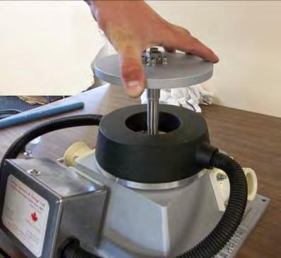
1 BEARINGS, SERVICE & ASSEMBLY IMPORTANT Bearing maintenance is important. You should replace bearings ONCE PER YEAR or as soon as you notice any looseness from wear. If they are too loose, severe damage to both the rotor and the stator can result. Check the clearance often making sure you can insert two business cards (or something the same thickness) between the rotor magnets and the stator if the machine is adjusted for maximum power. You can also raise the stator all the way which reduces the downward attraction of the magnets to make it easier to feel roughness or looseness in the bearings when turning the rotor by hand. Even if the bearings are not worn, changing them once per year will help keep the area free of corrosion and make future bearing changes easier. This machine uses three stainless steel 6203 ball bearings with contact seals. Bearing changes will be easier if the rotor is first raised as far as it will go as this will reduce the magnetic attraction. See the section on output adjustment for this. First, the turbine runner must be removed. The Stream Engine can be equipped with either of two types of turbine runner, the standard turgo or the low-flow runner. The turgo is removed from the shaft by first securing the magnet rotor on the top of the machine from rotating using the supplied ¼ diameter steel pin inserted into one of the holes in the edge of the rotor. Then the turgo runner can be unscrewed from the shaft by turning it in a counter-clockwise direction, just like a nut would be. If you cannot hold the runner securely with your hands, you may have to drive wooden wedges between the runner edge and the housing to keep it from moving and then turn the rotor. The low-flow runner can be removed by unscrewing the center bolt using a 5/16 (8mm) Allen wrench. With either runner removed, you will now have access to the four 7/16 (11 mm) nuts that secure the generator to the housing. Once the generator is removed, you will need to unscrew the stainless steel shaft adapter in the case of the low flow runner by turning it with the supplied longer pin. Now you can proceed to remove the shaft and magnet rotor of either type of machine by following these directions: 1. Lift the shaft and rotor assembly out of the generator stator (the black plastic part). This may require extra force like the use of a press if there is corrosion. 2. Unscrew two 7/16 (11 mm) bolts and washers that retain the bearings (older machines have 4 Phillip head screws). 3. With the Stream Engine sitting inverted, push out the bearings from the housing or tap the bearings out with a block of wood. This may require a press in some situations. 4. Insert new 6203 bearings. Using stainless steel bearings will keep corrosion to a minimum, extend bearing life, and make future bearing changes easier. 5. Reassemble. Note: Replace the washer and the spacer above the turgo or the shaft adapter with the spacer above the washer as shown in the following pictures. NOTE: BE VERY CAREFUL HANDLING THE ROTOR ASSEMBLY. THE MAGNETS ARE EXTREMELY POWERFUL AND WILL ATTRACT ANY NEARBY STEEL OR IRON OBJECTS. AVOID PUTTING FINGERS WHERE THEY COULD BE PINNED BETWEEN THE MAGNETS AND ANY STEEL OR IRON.


2 Pin inserted to hold rotor Unscrew turgo wheel Turgo removed Turgo with its washer and spacer Low flow wheel with center bolt Unscrew center bolt with 9/16 (14mm) socket or wrench Shaft adaptor of low flow wheel Remove generator mounting nuts and washers


 head bolt is loosened while using the pin to keep the rotor from turning.")
3 Generator removed for low flow version Remove low flow wheel shaft adaptor Shaft adaptor, washer, and spacer Once either style of wheel is removed the rotor should be raised until the magnetic attraction is low enough to separate the rotor from the stator. This is more easily done if the generator is placed back on the housing. To increase this distance and reduce the magnetic flux level, first insert the 1/4" pin supplied in one of the holes in the edge of the rotor. Then the smaller 7/16"(11 mm) head bolt is loosened while using the pin to keep the rotor from turning. Now you can turn the larger 3/4 bolt, which will force the rotor up. Each full turn of the bolt will move the rotor vertically (1.25 mm).


4 Rotor raised Carefully lift rotor Magnetic rotor shaft hub assembly removed Two 7/16 (11mm) bolts Remove bearing retaining bolts Invert stator to remove bearings Carefully tap with a piece of wood if needed


5 Bearings removed Top side of stator with bearings removed Clean bearing carrier Press in 3 new bearings Bearings inserted, reassemble


6 If low flow version, replace shaft adaptor Be sure to replace spacer first, then washer Spacer and washer placed Shaft adaptor replaced Tighten shaft adaptor Readjust height of rotor


 Generator replaced, ready for runner Replace")


7 Lowering rotor height and locking in place. Final adjustment for power output should be done after the turbine is reinstalled and the power output is read with the digital multi meter. Minimum rotor height air gap at least (0.5mm) Generator replaced, ready for runner Replace turgo runner, hand tighten Replace low flow runner with center bolt, tighten bolt ** Always turn the rotor by hand before starting the machine to check for rubbing**. Remove the pin in the rotor edge before starting the machine.
Subaru 5-Speed Double Adjustable Short Throw Shifter
 Subaru 5-Speed Double Adjustable Short Throw Shifter 1999+ Subaru Impreza 5-Speed 2004-2005 Subaru Forester XT 5-Speed Congratulations on your purchase of the COBB Tuning Double Adjustable Short Throw
LINDGREN-PITMAN General Maintenance of Lindgren-Pitman Hydraulic Systems & Equipment
 LINDGREN-PITMAN General Maintenance of Lindgren-Pitman Hydraulic Systems & Equipment Page 1 Lindgren-Pitman hydraulic driven equipment is designed to give long reliable service with a minimum of repairs
920 Remote Control Switches
 920 Remote Control Switches REMOTE CONTROL SWITCHES Service Bulletin This service bulletin for ASCO 920 Remote Control Switches explains how to replace the main s, operator coil, control s, and how to
Rugged Ridge Spartacus HD Tire Carrier Kit Install
 Rugged Ridge Spartacus HD Tire Carrier Kit Install Installation Time: 2 hours Tools Required: Ratchet ¾ socket 19 mm socket 13 mm socket 10 mm socket 19 mm Wrench 10 mm wrench 6mm Allen Wrench T50 torx
EZ-Glide Wheels Installation Patent Pending Revised 8/23/2011
 EZ-Glide Wheels Installation Patent Pending Revised 8/23/2011 Questions: Lakeside Quilt Co. Jack Boersma Toll Free (888) 361-4806 www.lovetoquilt.com Cell (406) 270-4715 sales@lovetoquilt.com Toll Free
The LH1000. Low Head Propeller Turbine. Personal Hydropower. Owner s Manual PLEASE READ CAREFULLY. Made in Canada
 The LH1000 Low Head Propeller Turbine Personal Hydropower Owner s Manual PLEASE READ CAREFULLY Made in Canada by Energy Systems and Design Ltd. PO Box 4557 Sussex NB Canada E4E 5L7 Phone +1 (506) 433-3151
Q-04: Replace Brake Shoes/Adjust Brakes
 Page 1 of 12 Q-04: Replace Brake Shoes/Adjust Brakes SAFETY FIRST Follow all Caterpillar facility safety standards when performing this task. The Electrician performs a lock and tag after the block has
LINDGREN-PITMAN General Maintenance of Lindgren-Pitman Hydraulic Systems & Equipment
 LINDGREN-PITMAN General Maintenance of Lindgren-Pitman Hydraulic Systems & Equipment Page 1 Lindgren Pitman hydraulic driven equipment is designed to give long reliable service with a minimum of repairs
MAINTENANCE ROAD 2013 WHEELS TECHNICAL MANUAL
 2013 WHEELS TECHNICAL MANUAL ROAD CYCLOCROSS PISTA GROUPSET TYPE OPERATION REVISION DESCRIPTION ROAD GROUPSETS CONE / CUP MOVEMENT 002 1/2011 SERVICING FRONT HUB ASSEMBLY PRODUCTS ON WHICH THE PROCEDURE
This suspension system was developed using a Maximum tire size of 33 X 12.5 with a 17 x 9 aftermarket wheel with 4 1/2-5 backspacing..
 92174700 Thank you for choosing Rough Country for your suspension needs. 2005-15 TACOMA 6 Kit Rough Country recommends a certified technician install this system. In addition to these instructions, professional
 This document provides instructions for removing and installing a Front Wheel / Rotor on a Ducati Superbike. The torque values used are for the 748/916/996 from 1994 to 2001 and may be applicable for later
EVO-1162 EVO Tailgate Tire Carrier
 EVO-1162 EVO Tailgate Tire Carrier Bill of Materials EVO-1162 Tailgate Tire Carrier Part number Description Quantity EVO-12161 EVO Tailgate Tire Carrier 1 EVO-12162 Bolt Plate 1 EVO-12163 Wheel Mount 1
STEP 1 Clutch Slave Cylinder Piston Removal and Installation
 STEP 1 Clutch Slave Cylinder Piston Removal and Installation This step is mandatory as the Clutch Adjustment Screw will remain bolted in place and you will not be able to remove the Primary Drive Cover
Universal Tall HoneyBadger Chase Rack Installation Instructions
 PREPARATION Universal Tall HoneyBadger Chase Rack Installation Instructions 1. Disconnect the negative terminal on the battery. Park the vehicle on level ground and set the emergency brake. 2. We recommend
Wheel Bearing Replacement Passat TDI
 Rear Bearing/hub assembly replacement This is a fairly straight forward process. Pictures are not necessary for most of this procedure for a person with skills to do this repair. Anyone who thinks they
2014 F /6 LIFT KIT
 92157500 2014 F-150 4 /6 LIFT KIT THANK YOU FOR CHOOSING ROUGH COUNTRY FOR YOUR SUSPENSION NEEDS. Rough Country recommends a certified technician install this system. In addition to these instructions,
632 Western Avenue Henniker, New Hampshire Tel. (603) Fax (603) POSITION OF THE ROLLER PLATES
 Fax (603) POSITION OF THE ROLLER PLATES") POSITION OF THE ROLLER PLATES The roller plate must be positioned as shown. The measurement to both of the roller plates is taken from the face of the kingpin shaft to the inside edge of the roller wheel
POSITION OF THE ROLLER PLATES The roller plate must be positioned as shown. The measurement to both of the roller plates is taken from the face of the kingpin shaft to the inside edge of the roller wheel
TOYOTA TUNDRA BIG BRAKE KIT Section I - Installation Preparation
 TOYOTA TUNDRA 2007- BIG BRAKE KIT Section I - Installation Preparation Part Number: PTR09-34070 Kit Contents Item # Quantity Reqd. Description 1 1 Brake Rotor, LH Front 2 1 Brake Rotor, RH Front 3 1 Brake
Steeda Bumpsteer Kit (94-04) - Installation Instructions
 - Installation Instructions") Steeda Bumpsteer Kit (94-04) - Installation Instructions The below installation instructions work for the following products: Steeda Bumpsteer Kit (94-04) Please read through the instructions carefully
Steeda Bumpsteer Kit (94-04) - Installation Instructions The below installation instructions work for the following products: Steeda Bumpsteer Kit (94-04) Please read through the instructions carefully
09-UP FORD F150 6 LIFT KIT
 92159800 09-UP FORD F150 6 LIFT KIT THANK YOU FOR CHOOSING ROUGH COUNTRY FOR YOUR SUSPENSION NEEDS. Rough Country recommends a certified technician install this system. In addition to these instructions,
3/8 Universal Joint Phillips Head Screwdriver
 Magnetic retrieval tool Pliers 1/4 Ratchet Drive T-35 Torx Socket 3/8 Ratchet Drive 5mm Allen Head Socket Torque Wrench 7-3/8 Drive Extension Flat Head Screwdriver 10mm Socket 8mm Socket 3/8 Universal
The Stream Engine. Personal Hydropower. Owner s Manual PLEASE READ CAREFULLY. Made in Canada
 The Stream Engine Personal Hydropower Owner s Manual PLEASE READ CAREFULLY Made in Canada by Energy Systems and Design Ltd. PO Box 4557 Sussex NB Canada E4E 5L7 Phone +1 (506) 433-3151 Fax +1 (506) 433-6151
*1553BAG3* F-150 2WD 4 /5 /6 LIFT KIT 1553BAG3
 *1553BAG3* 1553BAG3 921553220 2015-16 F-150 2WD 4 /5 /6 LIFT KIT THANK YOU FOR CHOOSING ROUGH COUNTRY FOR YOUR SUSPENSION NEEDS. Rough Country recommends a certified technician install this system. In
Installation Manual TWM Performance Short Shift Kit Stage 1 and Stage 2 MazdaSpeed 6
 Page 1 Installation Manual TWM Performance Short Shift Kit Stage 1 and Stage 2 MazdaSpeed 6 Please Note: It is preferable to park on a flat surface, as you will have to engage and disengage the hand brake
Maintenance Information
 16572679 Edition 2 May 2014 Air Drill QP Series Maintenance Information Save These Instructions Product Safety Information WARNING Failure to observe the following warnings, and to avoid these potentially
Spikes-Spider Hub Installation
 Spikes-Spider Hub Installation The instructions that are provided with the Spikes Spiders are pretty good. I've created this page for two reasons: to show those that are thinking of buying a set exactly
3.2 DRIVE TORQUE HUB. Roll, Leak and Brake Testing SECTION 3 - CHASSIS & TURNTABLE. 3-2 JLG Lift
 3.2 DRIVE TORQUE HUB Roll, Leak and Brake Testing 10 LUG PATTERN Torque-Hub units should always be roll and leak tested before disassembly and after assembly to make sure that the unit's gears, bearings
09-12 Dodge 4WD Leveling Kit
 9235900 09-12 Dodge 4WD 1500 2.5 Leveling Kit Thank you for choosing Rough Country for all your suspension needs. DOES NOT FIT TRX PACKAGE VEHICLES!! Rough Country recommends a certified technician install
Slave Cylinder Weep Hole Drilling Procedure
 Slave Cylinder Weep Hole Drilling Procedure Tools Required: T20 Torx Driver T25 Torx Driver T25 Torx Bit with ¼ Ratchet Wrench 4mm Hex Key (Allen wrench) 5mm Hex Key 6mm Hex Key 8mm Hex Key 12mm Hex Key
Rekluse Motor Sports. The e-axle KTM. Installation Guide Copyright 2006 Rekluse Motor Sports e-axle Revision 1.
 Rekluse Motor Sports The e-axle 2003 2007 KTM Installation Guide Copyright 2006 Rekluse Motor Sports e-axle Revision 1.000 RMS 2733 195-2733C Manual Revision: 032207 Rekluse Motor Sports, Inc. 110 E. 43
The Driveshaft Shop One Piece Aluminum Driveshaft Install for GT/BOSS
 The Driveshaft Shop One Piece Aluminum Driveshaft Install for 2011-14 GT/BOSS Tools and Equipment needed: Install time: approximately 2-3 hours Ratcheting socket wrench socket extensions 1/2 drive breaker
Operation and Maintenance Instructions
 Operation and Maintenance Instructions One Research Drive Stratford, CT 06615 (203) 375-0063 www.sonicmixing.com 1 Installation and Start-up Do not perform following adjustments without disconnecting power
The Stream Engine. Owner s Manual Please Read Carefully. PO Box 4557 Sussex NB Canada E4E 5L7
 The Stream Engine Owner s Manual Please Read Carefully PO Box 4557 Sussex NB Canada E4E 5L7 Phone +1 (506) 433-3151 Fax +1 (506) 433-6151 Email: support@microhydropower.com Website: www.microhydropower.com
Front Suspension Redo
 Front Suspension Redo Message: First, thanks to all the previous posters for guidance in my doing the suspension. As thanks, here s the updated document for doing the front suspension. Procedure: While
Compressor - Install (E.40.C.31 - F.10.A.15)
") Compressor - Install (E.40.C.31 - F.10.A.15) 1. Set the compressor on its mount and secure into place using the four bolts. Connect the refrigerant suction line (5) and the discharge line (4). Install
Compressor - Install (E.40.C.31 - F.10.A.15) 1. Set the compressor on its mount and secure into place using the four bolts. Connect the refrigerant suction line (5) and the discharge line (4). Install
Instructions for changing bearings on all B&C Technologies SP and HP models
 Instructions for changing bearings on all B&C Technologies SP and HP models Tools and material required: 30 mm socket Socket handle with extension or air impact wrench Regular Screwdriver Phillips head
POWER STEERING PUMP REBUILDING SPK101 Read instructions completely before removal & disassembly
 POWER STEERING PUMP REBUILDING SPK101 Read instructions completely before removal & disassembly DISASSEMBLY: 1. Remove pump from car and allow to drain. 2. Remove pulley from front of pump. This requires
Service Bulletin. HIITMill (X) Brake Lever Drift
 Brake Lever Drift") HIITMill (X) Brake Lever Drift Applies to: HIITMill (9-4590) + HIITMIll X (9-4640) On some HIITMill and HIITMill X units, the brake lever can drift when the user is Rev. A applying load to the belt. This
HIITMill (X) Brake Lever Drift Applies to: HIITMill (9-4590) + HIITMIll X (9-4640) On some HIITMill and HIITMill X units, the brake lever can drift when the user is Rev. A applying load to the belt. This
Start Up & Troubleshooting Manual. Resfab Equipment Inc. St Jean Sur Richelieu Website: resfab.com
 Start Up & Troubleshooting Manual Resfab Equipment Inc. 725 Rossiter St Jean Sur Richelieu 1 450 359 0800 Website: resfab.com Yogurt Blender Service Manual Page SECTION 1: Start Up and Repair... 3 thru
Maintenance Information
 16584062 Edition 3 December 2013 High Torque Reversible Angle Screwdrivers and Angle Wrenches QA1L High Torque Series Maintenance Information Save These Instructions Product Safety Information WARNING
Maintenance Information
 16575219 Edition 4 October 2013 Air Screwdrivers QP1P, QP1S and QP1T Series Maintenance Information Save These Instructions Product Safety Information WARNING Failure to observe the following warnings,
ALLOY USA AXLE INSTALLATION (99-04 GT, Mach 1)
") ALLOY USA AXLE INSTALLATION (99-04 GT, Mach 1) Time Necessary: Approximately 4 hours Tools Required: Wrenches: 8mm, 13mm, 15mm, 5.5 mm allen, 6mm allen Sockets: 5/8, 3/4 Ratchet Floor Jack Jack Stands
ALLOY USA AXLE INSTALLATION (99-04 GT, Mach 1) Time Necessary: Approximately 4 hours Tools Required: Wrenches: 8mm, 13mm, 15mm, 5.5 mm allen, 6mm allen Sockets: 5/8, 3/4 Ratchet Floor Jack Jack Stands
CHASSIS CONTENTS FRONT WHEEL 6-1 FRONT BRAKE 6-6 FRONT FORK 6-14 STEERING STEM 6-20 REAR WHEEL AND REAR BRAKE 6-25 SUSPENSION 6-31 REAR SWING ARM 6-36
 CHASSIS CONTENTS FRONT WHEEL 6-1 FRONT BRAKE 6-6 FRONT FORK 6-14 STEERING STEM 6-20 REAR WHEEL AND REAR BRAKE 6-25 SUSPENSION 6-31 REAR SWING ARM 6-36 6 6-1 CHASSIS FRONT WHEEL REMOVAL Support the machine
SERVICE MANUAL 200 SERIES MOTORIZED 20352, 20452, 20551, 20552, AND MODELS
 Section: MOYNO 500 PUMPS Page:1 of 4 Date: March 1, 1998 SERVICE MANUAL MOYNO 500 PUMPS 200 SERIES MOTORIZED 20352, 20452, 20551, 20552, 22051 AND 22052 MODELS DESIGN FEATURES Housing: AISI 316 stainless
BELT DRIVE SYSTEM TROUBLESHOOTING CHART CAUSES CORRECTIVE ACTION ENGINE RUNS BUT PADDLES DO NOT TURN
 ELT DRIVE SYSTEM TROULESHOOTING HRT USES ORRETIVE TION ENGINE RUNS UT PDDLES DO NOT TURN elt jumps off the drive pulleys. Inspect the belt for damage. Replace belt if needed. heck belt alignment. Idler
COYOTE ENTERPRISES, INC. 9/10 BLAST WHEEL MAINTENANCE & ASSEMBLY MANUAL
 COYOTE ENTERPRISES, INC. 9/10 BLAST WHEEL MAINTENANCE & ASSEMBLY MANUAL Parts & Machinery for the Abrasive Blast Industry 27301 East 121st Street Coweta, Oklahoma 74429 (918) 486-8411 Fax (918) 486-8412
09-13 FORD F150 4 LIFT KIT
 92159900 09-13 FORD F150 4 LIFT KIT THANK YOU FOR CHOOSING ROUGH COUNTRY FOR YOUR SUSPENSION NEEDS. Rough Country recommends a certified technician install this system. In addition to these instructions,
POWERSHIFT TRANSMISSION
 1. Specifications... 5-3 2. Structure... 5-4 2.1 Torque converter... 5-4 2.2 Transmission... 5-5 2.3 Power Train Line... 5-6 2.4 Control Valve... 5-7 2.5 Main Regulator Valve... 5-7 2.6 Torque Converter
Turner M50 Manifold Adapter Install. April 26, 2012
 April 26, 2012 Models: 1996-99 E36 328i/M3; 1997-98 E39 528i, 1997-98 Z3 2.8, 1998-2000 MZ3 S52 Product(s): Turner M50 Manifold Adapter Kit Subject: Installation Guidelines and Tips This guide will aid
Repair Instructions. Replacing and Installing a New Elevation Motor. Elite Models that Apply: EL01-3. Step Description Tools Picture Removing The Case
 Elite Models that Apply: EL01-3 Step Description Tools Picture Removing The Case Step 1.) Unscrew the (6) phillips-head screws along the bottom of the red case where it attaches to the chassis of the machine.
Installation Instructions
 Instructions Created by an: 1986-1995 Toyota Pickup 4Runner Hilux Front Ball Joint Spacer Kit - 2.5" 64mm Lift by Low Range Off-Road (SKU# TSP-BJS-1.5 & TSP-BJS-1.5-W/Shocks) Installation Instructions
2014 F /6 LIFT KIT
 92157500 2014 F-150 4 /6 LIFT KIT THANK YOU FOR CHOOSING ROUGH COUNTRY FOR YOUR SUSPENSION NEEDS. Rough Country recommends a certified technician install this system. In addition to these instructions,
SUSP-09, Rear Wheel Bearing Replacement - Steel Trailing Arm. Acrobat Printable Version
 SUSP-09, Rear Wheel Bearing Replacement - Steel Trailing Arm Introduction Acrobat Printable Version I'd like to thank Ben Davis for providing the pictures for this procedure. Ben took the time to take
REMOVAL OF ALTERNATOR
 CH6 CHARGING SYSTEM ALTERNATOR REMOVAL OF ALTERNATOR 1. DISCONNECT CABLE FROM NEGATIVE TERMINAL OF BATTERY CAUTION: Work must be started after approx. 20 seconds or longer from the time the ignition switch
2015 F /5 /6 LIFT KIT
 92155700 2015 F-150 4 /5 /6 LIFT KIT THANK YOU FOR CHOOSING ROUGH COUNTRY FOR YOUR SUSPENSION NEEDS. Rough Country recommends a certified technician install this system. In addition to these instructions,
Rekluse Motor Sports. The z-start Clutch LTR 450. Installation Guide Copyright 2002 Rekluse Motor Sports z-start Revision 3.
 Rekluse Motor Sports The z-start Clutch LTR 450 Installation Guide Copyright 2002 Rekluse Motor Sports z-start Revision 3.000 RMS166 LTR 450 191-266 Manual Revision: 032306 Rekluse Motor Sports, inc. 110
Maintenance Information
 04581245 Edition 2 May 2014 Air Grinder, Die Grinder and Sander Series G2 (Angle) Maintenance Information Save These Instructions Product Safety Information WARNING Failure to observe the following warnings,
SERVICE MANUAL for. Engine-to-Generator. Part Number used on. John Deere Engine Driven Aircraft Ground Power Single-Bearing Generator Sets
 TO-216 SERVICE MANUAL for Engine-to-Generator FLEXIBLE COUPLING Part Number 181267 used on John Deere Engine Driven Aircraft Ground Power Single-Bearing Generator Sets manufactured by HOBART BROTHERS COMPANY
Installation Manual TWM Performance Short Shifter Subaru Forester up to 2005
 - 1 - Installation Manual TWM Performance Short Shifter Subaru Forester up to 2005 Please Note: It is preferable to park on a flat surface, as you will have to engage and disengage the hand brake and shift
COLD AIR INTAKE INSTALLATION INSTRUCTIONS PART NUMBER D A. APPLICATION: E36/7 M-Roadster or M-Coupe 3.
 COLD AIR INTAKE INSTALLATION INSTRUCTIONS PART NUMBER D760-0323A APPLICATION: 1998-00 E36/7 M-Roadster or M-Coupe 3.2 Liter PARTS LIST Air Filter Assembly 3 1/2" Tube Intake Shield Silicone Hose Airflow
Lowering Spring Installation on a Mustang GT
 Lowering Spring Installation on a 99-04 Mustang GT This installation is very the same installation that many of the 79-04 Mustangs excluding Cobra require. Time to install: 2-3 hours to do alone with a
5.7 BigBully CAI Installation Instruction Sheet
 5.7 BigBully CAI Installation Instruction Sheet Please Read Carefully Our 5.7 BigBully CAI is designed to fit in the stock air box area. If you have altered this area in any way then it is your responsibility
Gearbox Assembly 101. Introduction. Before Beginning. By Mark Schutzer 4/13/06
 Gearbox Assembly 101 By Mark Schutzer 4/13/06 Introduction If you are planning to re-motor an old brass locomotive you may want to upgrade to a new gearbox at the same time. The early 60 s and 70 s gearboxes
Installation Instructions
 Installation Instructions Rear Disc Brake Conversion Kit Item # RC4001, RC4001X Applications: Mopar 7.25, 8.25, 9.25 Axles Thank you for choosing Leed Brakes for your automotive product needs. Before you
Maintenance Information
 16575243 Edition 2 October 2013 Air Screwdrivers 1R Series Maintenance Information Save These Instructions Product Safety Information WARNING Failure to observe the following warnings, and to avoid these
Procedure Replacing a Cover
 Procedure 7.1 - Replacing a Cover Cover Removal 1. Remove two screws, one each side, from the front of the top cover. Remove the top cover. See Diagram 7.1. Diagram 7.1 - RBK 815 Covers Top Cover Left
EGR Performance Brakes Assembly Instructions DODGE DANA 70 '87 - '93 (Will not fit stock sized dual rear wheels)
") EGR Performance Brakes Assembly Instructions DODGE DANA 70 '87 - '93 (Will not fit stock sized dual rear wheels) Got Brakes? Parts List (2) Vented Rotors (2) Multi hole Cable Mount & L Brkt (2) Axle Tube
EGR Performance Brakes Assembly Instructions DODGE DANA 70 '87 - '93 (Will not fit stock sized dual rear wheels) Got Brakes? Parts List (2) Vented Rotors (2) Multi hole Cable Mount & L Brkt (2) Axle Tube
Maintenance Information
 80234313 Edition 1 June 2006 Air Grinder, Die Grinder, Sander and Belt Sander Series G1 (Angle) Maintenance Information Save These Instructions WARNING Always wear eye protection when operating or performing
Rear Bumper Installation Instructions
 KEY TO COMPONETS A. 1 ea. Rear bumper B. 2 ea. Mounting L bracket C. 11 ea. M12x1.75 hex head bolt D. 4 ea. M12x1.75 hex head bolt E. 6 ea. M12 Hex head lock nut F. 9 ea. Pressure washer G. 19 ea. M12
SUPERCHARGER. ON-VEHICLE INSPECTION 1. INSPECT SUPERCHARGER OIL LEVEL HINT: With the engine cold, check the oil level on the dipstick.
 EG45 ONVEHICLE INSPECTION 1. INSPECT OIL LEVEL HINT: With the engine cold, check the oil level on the dipstick. (a) Park the vehicle on a level spot and turn the engine off. (b) 4WD: Remove the LH front
Maintenance Information
 80234313 Edition 2 May 2014 Air Grinder, Die Grinder, Sander and Belt Sander Series G1 (Angle) Maintenance Information Save These Instructions Product Safety Information WARNING Failure to observe the
Assault Air Bike Assembly Instructions
 Assault Air Bike Assembly Instructions Tools Needed: Box Cutter 6mm Hex Wrench Phillips Screw Driver 13mm Wrench 22mm Wrench 15mm Wrench Step 1: Lay the Assault Airbike Bike box on the ground. Step 3:
Version 1.4 Operating instructions Czech Republic
 Version 1.4 Operating instructions Czech Republic Please check updates of operating instructions at www.rotomotor.cz, that your engine has still the best care. (can happen important changes that will lead
2. With the rear door open remove pull-style clip from the passenger side just below the door latch.
 LoD Offroad FJ Cruiser Rear Bumper with Tire Carrier Installation Instructions 1. Begin with removing factory spare from the rear door. 2. With the rear door open remove pull-style clip from the passenger
FlexJet Carriage Circuit Board (PCB) Replacement
 Replacement") P/N: 111484 R0 14140 NE 200th St. Woodinville, WA. 98072 PH: (425) 398-8282 FX: (425) 398-8383 ioline.com FlexJet Carriage Circuit Board (PCB) Replacement Notices: Warning! Ensure that all AC power cables
P/N: 111484 R0 14140 NE 200th St. Woodinville, WA. 98072 PH: (425) 398-8282 FX: (425) 398-8383 ioline.com FlexJet Carriage Circuit Board (PCB) Replacement Notices: Warning! Ensure that all AC power cables
SISU DP-330 DRIVE GEAR. Maintenance Manual
 SISU DP-330 DRIVE GEAR Maintenance Manual Sisu Axles, Inc. Autotehtaantie 1 PO Box 189 Fin-13101 Hameenlinna Finland Phone +358 204 55 2999 Fax +358 204 55 2900 DP330DG.PDF (3/2007) TABLE OF CONTENTS
Step-by-Step Instructions for ieq45 R.A. Worm Installation/Replacing September 2013
 Step-by-Step Instructions for ieq45 R.A. Worm Installation/Replacing September 2013 These instructions serve to explain how to Replace a R.A. worm; Adjust a RA worm/wheel meshing; Inspect and clean a RA
Geared Drives 200Z PSRU Zero Offset Gearbox with Centrifugal Clutch Assembly
 Instructions for Removing and replacing Gen X Gearbox with Geared Drives 200Z Prior to your gear box arriving: Using a strap or chain and an engine hoist to hold your engine up in the mount, remove your
RockyHydro. System Assembly Info Packet
 RockyHydro System Assembly Info Packet RockyHydro sells a wide degree of micro-hydro components for various kits. Our customers enjoy the benefit of being able to carefully match a turbine and generator
Installation Manual TWM Performance Short Shift Kit Estimated Installation Time: Tools required:
 Page 1 Installation Manual TWM Performance Short Shift Kit 1993-2001 Nissan Altima 1991-2001 Infiniti G20 1991-2001 Nissan Sentra- 200SX 1991-1993 Nissan NX 1986-1989 Nissan Stanza 1995-2001 Nissan Maxima
Stowe Cargo Management System
 Installation Guide Stowe Cargo Management System Table of Contents 1. Pre-Installation (Page 2) a. Notes, Installation Kit contents & Tools needed 2. How to Install the Stowe Cargo Management System (Pages
Ford F150 2 Suspension Kit
 92569000B Thank you for choosing Rough Country for all your suspension needs. 2014-17 Ford F150 2 Suspension Kit Rough Country recommends a certified technician install this system. In addition to these
C6 (includingg Z06) Catalog # 45034
 Catalog # 45034") Installation Instructionss Precision Sport Shifter Fits: 2008-20133 Corvette C6 (includingg Z06) Catalog # 45034 WORK SAFELY! For maximum safety, perform this installation on a clean, level surface and
Installation Instructionss Precision Sport Shifter Fits: 2008-20133 Corvette C6 (includingg Z06) Catalog # 45034 WORK SAFELY! For maximum safety, perform this installation on a clean, level surface and
Rear Strong-Strut. Installation Instructions
 Rear Strong-Strut Installation Instructions Please read instructions completely before installing the rear Strong-Strut Forward Installation of the rear Strong-Strut is quite simple and involves the removal
The Ford Model A Water Pump
 The Ford Model A Water Pump George Washington Chapter, Inc. 3903 Old Lee Highway Fairfax, VA 22030 1 Table of Contents Introduction/Specifications.. 3 1. Water Pump Inspection and Removal. 4 a. Removal..
SACHS Clutches The Intelligent Choice for the Long Haul
 SACHS Clutches The Intelligent Choice for the Long Haul Twin XTend Clutch Installation Objectives: Identification Operation Tools Installation Troubleshooting Identification 15.5 Self Adjusting Clutch
SERVICE MANUAL OF SERVOMOTORS HD/HR RANGE
 SERVICE MANUAL HD/HR RANGE OF SERVOMOTORS ISSUE 2 WARNING Servomotors contain magnetic material which will attract metal particles. Care should be taken when dismantling motors to avoid this. All D.C.
Installation Instructions
 Preparing your vehicle to install your brake system upgrade 1. Rack the vehicle. 2. If you don t have a rack, then you must take extra safety precautions. 3. Choose a firmly packed and level ground to
WORK INSTRUCTION READ FIRST. IF IN DOUBT
 WORK INSTRUCTION PAGE 1 OF 9 FIELD CHANGE INSTRUCTION : TO CHANGE A BACK DOOR AND SIDE LIFT PROCEDURE: Step 1. How to remove and replace the rear door of a canopy. Step 2. How to remove the side lift up
Rear End Installation and Bearing Kit - 8.8in (86-12 V8; V6)
") Rear End Installation and Bearing Kit - 8.8in (86-12 V8; 11-13 V6) Tools Required: Jack Stands 5 Floor Jack 2 Oil Pans 1 Wheel Blocks 2 Differential Oil 3 qts Friction Modifier 3 bottles Tube of Black
Rear End Installation and Bearing Kit - 8.8in (86-12 V8; 11-13 V6) Tools Required: Jack Stands 5 Floor Jack 2 Oil Pans 1 Wheel Blocks 2 Differential Oil 3 qts Friction Modifier 3 bottles Tube of Black
PRODUCT USE INFORMATION
 921522000A *52200BAG3* 52200BAG3 Thank you for choosing Rough Country for all your suspension needs. 2009-18 Ford F150 2 Leveling Kit Rough Country recommends a certified technician install this system.
PRODUCT USE INFORMATION
 9RC61000 Jeep YJ Body Lift Thank you for choosing Rough Country for all your suspension needs. This body lift fits both manual and Automatic equipped vehicles!!! Refer to last page of this Instruction
SE206 Installation & Removal Guide
 SE206 Installation & Removal Guide Tools Needed: Sockets 5/8" socket 9/16" socket 1/2 socket 18mm 3/8 socket 1-1/16 socket Wrenches 5/8" wrench 1/2" wrench Sealers/ Lubricants Grease Silicone sealant Gear
Wren Inverted Suspension Forks with Keyed Stanchions and TwinAir System
 Owner s Manual Wren Inverted Suspension Forks with Keyed Stanchions and TwinAir System Congratulations You have just purchased a Wren Inverted Suspension Fork. The culmination of years of design, testing
A/C COMPRESSOR SERVICING Article Text 1991 Saab 9000 For Copyright 1997 Mitchell International Friday, October 15, :22PM
 Article Text ARTICLE BEGINNING 1991 GENERAL SERVICING Compressor Service * PLEASE READ THIS FIRST * CAUTION: When discharging air conditioning system, use only approved refrigerant recovery/recycling equipment.
09-UP F150 2WD 6 LIFT KIT
 92157300 09-UP F150 2WD 6 LIFT KIT THANK YOU FOR CHOOSING ROUGH COUNTRY FOR YOUR SUSPENSION NEEDS. Rough Country recommends a certified technician install this system. In addition to these instructions,
Z TECHNICAL INSTRUCTIONS
 ÍNDICE: Z40 2.0 TECHNICAL INSTRUCTIONS 1.- Error list 2.- Replace the control board 3.- Opening the machine 4.- Replace the power board 5.- Dismantling motor and gear box 6.- Assembly of gear box 7.- Pushing
AUTOMATIC TRANSAXLE AUTOMATIC TRANSAXLE SYSTEM... COMPONENT PARTS...
 SYSTEM....... COMPONENT PARTS.................... OIL PUMP.............................. DIRECT CLUTCH........................ FORWARD CLUTCH..................... SECOND BRAKE........................ UNDERDRIVE
Installation Guide for Rough Country 30 in. Chrome Series LED Light Bar w/ Hood Mounting Brackets
 Installation Guide for Rough Country 30 in. Chrome Series LED Light Bar w/ Hood Mounting Brackets Installation Time: 1 Hour Tools Required Trim removal tool (plastic or wood to prevent scratches on the
Dethatcher Kit Greensmaster 3000 Series
 Form No. 338 944 Dethatcher Kit Greensmaster 3000 Series Model No. 04493 Serial No. 3000000 and Up Operator s Manual English (EN) Contents Page Specifications............................... General Specifications.....................