AUTOMATIC SLACK ADJUSTER ECO MASTER
|
|
|
- Dinah Bell
- 6 years ago
- Views:
Transcription


1 AUTOMATIC SLACK ADJUSTER ECO MASTER
2 WORKING PRINCIPLE WORKING PRINCIPLE Braking process H E V Adjustment point SB Sequence of of the braking process H = Free stroke of the brake cylinder to cover the clearance (SB) between the brake lining and the brake drum. E = Elasticity of the wheel brake and its transmission elements. V = Increase in stroke due to wear and heating. SB = Clearance. Brake linings and brake drums are parts subject to wear. As the thickness of the material is reduced, the brake cylinder stroke increases by the value (V), meaning that the brake camshaft has to rotate further. At a maximum rotation of 17.5, depending on the version, the automatic adjustment mechanism of the ECO Master automatic slack adjuster makes the appropriate adjustment. As a result, the brake cyclinder stroke is always kept within the same optimum zone of action. The adjustment stroke is designed so there will always be a sufficient air gap even at higher levels of elasticity and thermal expansion.
3 WORKING PRINCIPLE WORKING PRINCIPLE 4 V 4 Brake camshaft torque Be rake camshaft tor q u Brake application H = Free stroke. H = Free stroke when the stroke is increased. E = Elasticity. V = Increase in stroke due to wear and heating. N = Adjustment corresponding to V. NB = Adjustment range. MA = Contact torque MA N NB H 5 E Hub Stroke Course 5 H E 1 Initial position (internal springs of the brake produce a negative cam torque. 2 Brake threshold overcome. 3 Clearance )mm = brake lining is in contact with the brake drum. 4 Maximum braking torque. 5 Initial position reached by releasing the brake. 4 Maximum braking torque, adjustment point is reached, the coupling sleeve engages in the next tooth space in the worm shaft. 5 Start of the adjustment range. N.B. In the adjustment range, the coupling sleeve rotates the worm shaft and with it, the worm gear and the brake camshaft. This reduces the clearance between the braking lining and the brake drum. The BPW ECO Master slack adjuster is designed to ensure there is always a sufficient amount of clearance even with large strokes, e.g. thermal expansion of the brake drum, brake lining wear, elasticity.


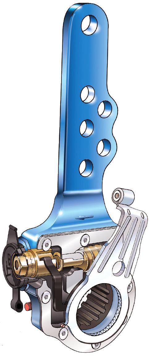
4 FUNCTIONAL DESCRIPTION DESCRIPTION Initial position Worm shaft Brake lever Coupling sleeve Reaction bracket Control level Adjustment lever Limit stop Initial Description The BPW ECO Master automatic slack adjuster is connected to the axle beam via the control lever and the reaction bracket. The inner stop of the control unit permits a lever travel of 30. This protects the adjusting device contained within against damage in the event of extreme strokes. The control lever is in a positive engagement with the adjustment lever. The latter engages in the coupling sleeve. The adjustment lever and the coupling sleeve are designed so the clearance is always optimum. The coupling sleeve has a special tooth profile on its end. The force of a compression spring causes this to engage in the gearing on the head of the worm shaft. Independent rotation of the worm shaft is prevented by the compression spring on the one hand and by the holding bracket on the other hand. The worm shaft head has a hexagonal profile and can be adjusted using a size 19 ring spanner. The plastic cap seals the entire coupling space. All adjustment parts are therefore accommodated in the protected interior of the slack adjuster. Its function cannot be affected by dirt, mositure, ice or snow. The internal springs in the brake exert a negative torque in the initital position. The coupling and adjustment are in the initial position.


5 FUNCTIONAL DESCRIPTION FUNCTIONAL DESCRIPTION Brake application The brake threshold is overcome when the automatic slack adjuster is operated. The brake lining is brought into contact with the brake drum. The adjustment lever moves against the upper grooved side of the coupling sleeve. Brake application Adjustment lever Coupling sleeve The coupling sleeve is turned by the adjustment lever as the cyclinder stroke increases. If the adjustment point is not reached, the teeth do not move on one position. The stroke to the adjustment point is set by the groove width and the length of the teeth on the coupling. Braking strokes within this range do not cause the automatic slack adjuster to reposition. Brake application If the adjustment point is reached during a braking process, the teeth on the coupling sleeve engage in the next tooth gap of the worm shaft Brake release Worm shaft Adjustment takes place when the brake is released during the last portion of the return stroke. The adjustment lever moves back and, once the clearance within the coupling has been overcome, applies a tractive force to the lower grooved side of the coupling sleeve.
6 FUNCTIONAL DESCRIPTION Adjustment In the adjustment range, the coupling sleeve is rotated by the engaged teeth, the worm shaft and with it, the worm gear and brake camshaft. This reduces the clearance between the brake lining and the brake drum. The adjusting device is designed to ensure there is always a sufficient amount of clearance even with large strokes (e.g. thermal expansion of the brake drum, brake lining wear, elasticity.) Adjustment The initial position is reached at the end of adjustment. The toothed coupling only adjusts in small, positive engagement steps from one position to the next. Its adjustment is not infinitely variable using static friction. This means the adjustment distance is always exact.


7 SET UP PROCEDURES Wear indicator All BPW drum brake axles are fitted with a brake lining wear indicator that is bolted directly to the camshaft adjacent to the slack adjuster. These are made of plastic material and coloured either black, or in the case of later versions, orange. When new linings are fitted, the indicator is set to the vertical position. As the lining wear takes place, and adjustment is taken up, the indicator will rotate with the camshaft. When the indicator has rotated 90 to the horizontal position the linings are due for replacement.


8 SET UP PROCEDURES ECO Master - Brake push rod length SET UP PROCEDURES The brake cylinder push rod length needs to be set correctly. In the example, a BPW standard air chamber bracket is shown on an H series axle. The correct effective push rod length for this axle is 227mm. The 227mm dimension is measured from the brake cylinder mounting interface to the centre line of the clevis pin hole with the brake in the OFF position. Other types may have different requirements for the effective push rod length dimension. If you are unsure about this dimension, contact BPW Technical Services with the axle code and this information can be verified. Brake cylinder installation BPW brake chambers Tighten alternate side lock nuts to 180Nm (180Nm-210Nm) (1) Tighten yoke lock nut to 80Nm Other chamber makes: Consult manufacturers mounting instructions The air chamber brackets are designed in such a way that the fixing holes for the cylinder are offset so as to allow the brake cylinder push rod to align to the appropriate lever hole position without having to use the +/-3 of deflection allowed by the cylinder manufacturer. Provision is made in the air chamber bracket to locate the external cylinder pull off spring. 120, 135, 150, 165 and 180mm hole positions are available in the bracket but in practice the 180mm position is seldom used. The 8mm thick brackets will accept both diaphragm and piston spring brake units without any additional reinforcement. Many different types of air chamber brackets are available across the BPW range of axles but all encompass the features listed. Always consult the cylinder manufacturer for mounting details.


9 SET UP PROCEDURES 2. Installation - ECO Master - The slack adjusters are secured with a nut and washer to give a positive location on the camshaft. This method prevents undue wear to the splines. The camshaft also falls short of full engagement into the slack adjuster splined boss preventing a step wearing into the splines. The slack adjuster is drawn up to either a shouldered end of the splines or to a snap ring, depending on the design of the camshaft. The splines are coated with BPW ECO Li Plus grease prior to assembly. Final tightening of the camshaft nut and positioning of the wear indicator is best left until all set up adjustments are made. The reaction bracket bolts should be loose at this stage.


10 SET UP PROCEDURES 2. Installation - ECO Master Brake off. Push rod length set. Remove rubber closure cap. 1. Adjust the auto slack into position so that the clevis pin can be engaged and secured. 2. The pin should pass freely into position and be lubricated prior to assembly. The adjustment bolt of the auto slack is a 19mm hexagon profile. By fully engaging a standard socket onto the adjustment bolt, the dog clutch is disengaged allowing the whole unit to be manipulated

11 SET UP PROCEDURES 3. Installation ECO Master With the 19mm socket fully engaged onto the adjusting bolt, align the pointer on the reaction bracket with the pin on the side of the slack adjuster. No more than hand pressure in the direction of the arrow should be required for this operation. REMEMBER: Brake off - pin and pointer aligned. ECO Master - pointer aligned Pin and pointer aligned correctly. Automatic adjustment function enabled.


12 SET UP PROCEDURES 4. Installation - ECO Master Double check that the brake is off and the pin and pointers are still aligned. Secure the reaction bracket to the inner camshaft bearing support plate. Setting free play a The objective is to set the lining to drum clearance to 0.7mm - 1.0mm. This is achieved by rotating the 19mm adjustment bolt of the auto slack until the free play equals 10-15% of the effective lever length dimension. Remember to fully engage the 19mm socket to disengage the internal clutch mechanism. Position the brake lining wear indicator and tighten the camshaft nut. Example: A set up with a 150mm brake lever length will have an initial free play of 15-22mm.
 Measure from the brake chamber front to centre of clevis pin. (standard overslung measurement = 227mm).")

 With a fully engaged 19mm socket and the wheel free to rotate, adjust the automatic slack adjuster until the brake is Just On -")
13 SET UP PROCEDURES ECO Master - Setting free play Adjustment procedures 1. Measurement method: a) Measure from the brake chamber front to centre of clevis pin. (standard overslung measurement = 227mm). b) Adjust until measurements is 10-15% greater. (Example: A set up with a 150mm brake lever length will have a final measurement of between 242mm and 249mm. ECO Master - Setting free play Adjustment procedures 2. Measurement method: a) With a fully engaged 19mm socket and the wheel free to rotate, adjust the automatic slack adjuster until the brake is Just On - DO NOT OVERTIGHTEN. b) Rotate the adjuster mechanism by a Half Turn (180 ). The free play should then be at least 12%. ECO Master - Fitting pull-off spring Lubricate the slack adjuster with BPW ECO Li Plus grease until clear grease emits from the adjustment bolt housing. Refit the rubber protective cover. Fit the external pull-off spring.
116 281 6100 info@bpw.co.uk")
14 BPW Limited Centurion Way, Meridian Business Park, Leicester LE19 1WH Phone + 44 (0) info@bpw.co.uk -
BPW Trailer axle HZF ECO Plus
 BPW Trailer axle HZF 900-5 ECO Plus L ( form closure ( square ) ) Brake SN 428 for ABS, with sensors Track 840 mm, Spring centre 950 mm, Booster bracket centre 4 mm for diaphragm cylinder, AGS ECO-Master,
Sisu S-Cam Drum Brakes
 Sisu S-Cam Drum Brakes (For hub reduction rear axles since 1992) Maintenance Manual Sisu Axles, Inc. Autotehtaantie 1 P.O. Box 189 FIN-13101 Hämeenlinna Finland Phone int + 358 204 55 2999 Fax int + 358
L LL. Workshop manual. BPW steering axles. BPW-WH-LL-L e
 L LL Workshop manual BPW steering axles BPW-WH-LL-L 35351701e Page 2 BPW-WH-LL-L 35351701e Valid: 01.02.2017 Subject to change without notice. Current versions and additional information can be found online
Operating and Installation Instruction. BPW Brake Components. BPW-EA-BK e - Version 2.0
 Operating and Installation Instruction BPW Brake Components BPW-EA-BK 37401801e - Version 2.0 Page 2 BPW-EA-BK 37401801e BPW Trailer Disc Brake - ECO Disc - Installation instructions for vehicle manufacturers!!
ASSEMBLY GUIDELINES AIR SUSPENSIONS. with Weld-on Axle Seats Series O/OM/OT
 ASSEMBLY GUIDELINES AIR SUSPENSIONS with Weld-on Axle Seats Series O/OM/OT PW Air Suspensions are available for installation in either B single or multi-axle configurations. The axles are connected to
Module 6: Air Foundation Brakes
 Air Brakes Terms and Definitions Basic Components That Make Up Air Foundation Brakes Types of Air Foundation Brakes Parts of a Cam Foundation Brake Parts of a Wedge Foundation Brake Parts of a Disc Foundation
ECO Plus 2 - The new generation of the proven BPW ECO Unit
 BPW-NEWS Allg 7125703e BPW NEWS BPW BERGISCHE ACHSEN ECO Plus 2 - The new generation of the proven BPW ECO Unit The BPW ECO Unit has proven itself millions of time over, and its ECO Plus version will be
1999 Honda Accord DX
 Installation 1. Clean tensioner pulleys. Ensure cylinder No. 1 is at TDC by aligning dimple on timing belt drive pulley with pointer on oil pump housing. See Fig. 4. Ensure camshaft pulley TDC marks are
Once properly aligned weld axle saddles to axle using welding practice as below.
 INSTALLATION & MAINTENANCE GUIDE 50 Series Suspensions Shackle bolts and rocker pivot bolts fitted with Nyloc type nuts must be tightened firmly allowing for rotational movement of bushed components. All
H K N. BPW Original spare parts. BPW trailer axles series H.. / K.. / N.. with drum brakes. BPW-EL-HKN e
 BPW Original spare parts BPW trailer axles series.. /.. /.. with drum brakes BPW-EL- 31021401e BPW-EL- 31021401e Your partner on the path to economic viability BPW Bergische Achsen ommanditgesellschaft
ASSEMBLY GUIDELINES AIR SUSPENSIONS. with Weld-on Axle Seats Series AL II
 ASSEMBLY GUIDELINES AIR SUSPENSIONS with Weld-on Axle Seats Series AL II PW Air Suspensions are available for installation in either B single or multi-axle configurations. The axles are connected to the
SD Bendix Manual Slack Adjusters DESCRIPTION ADJUSTING MECHANISM OPERATION
 SD-05-1200 Bendix Manual Slack Adjusters WORM SHAFT (LOCK SCREW) FIGURE 1 - POSITIVE LOCK TYPE SLACK ADJUSTER DESCRIPTION In an s-cam type foundation brake, the final link between the pneumatic system
Slack Adjuster. Table of Contents
 Slack Adjuster Table of Contents Sub-Headings Automatic Slack Adjuster Service 2 PayMaster Automatic Slack Adjuster 2 How the Automatic Slack Adjuster Works 2 Pressed-In, Sealed Actuator Boot 3 Handed
3 Axles and brakes. 3.1 Function and construction of the axles Construction Function
 3 Axles and brakes 3.1 Function and construction of the axles 3.1.1 Function Each wheel has an independent suspension system in the axle body (1), so that individual wheel suspension is provided. The swinging
URGENT : Ensure that the precautions relating to safety and cleanliness are adhered to (refer to the brochure: RECOMMENDATIONS - PRECAUTIONS).
.") PAGE 1 - b1eg1xp0 - removing - refitting timing belt removing - refitting timing belt INJECTION ES9J4S URGENT Ensure that the precautions relating to safety and cleanliness are adhered to (refer to the
PAGE 1 - b1eg1xp0 - removing - refitting timing belt removing - refitting timing belt INJECTION ES9J4S URGENT Ensure that the precautions relating to safety and cleanliness are adhered to (refer to the
Tech Note Truck 14 & 15.5 Twin Plate Cast Iron Type Installation Guidelines
 1. (14 & 15.5 ) Check condition of the flywheel. Grind to resurface or replace flywheel. Surface MUST BE machined or premature clutch failure can occur. Flywheel depth must be 2.938 (74.62mm) for 14 (350mm)
Workshop manual. BPW axle stub MVBF ST BPW-WH-MVBF ST e
 Workshop manual BPW axle stub MVBF ST 35.50.743.013-028 BPW-WH-MVBF ST 35221401e Page 2 BPW-WH-MVBF ST 35221401e BPW-WH-MVBF ST 35221401e Page 3 Contents BPW axles stub with drum brake S-camshaft SN 4218
Self-Adjust Clutch Installation Guide
 Self-Adjust Clutch Installation Guide 0 STOP! READ CAREFULLY BEFORE INSTALLING CLUTCH This clutch must be installed by a qualified installer. Improper installation or failure to replace or resurface the
SACHS Clutches The Intelligent Choice for the Long Haul
 SACHS Clutches The Intelligent Choice for the Long Haul Twin XTend Clutch Installation Objectives: Identification Operation Tools Installation Troubleshooting Identification 15.5 Self Adjusting Clutch
Tech Talk. Timing Belt 6VD1/6VE1
 Holden DOHC V6 Frontera 6VD1 3.2L 1999 2004 Jackaroo 6VE1 3.5L 1998 2004 Rodeo TF 6VD1 3.2L 1998 2003 Rodeo RA 6VE1 3.5L 2003 2005 Important: Read through all the instructions before proceeding with the
1989 Jeep Cherokee. STEERING COLUMN' '1989 STEERING Jeep Steering Columns STEERING COLUMN STEERING Jeep Steering Columns
 STEERING COLUMN 1989 STEERING Jeep Steering Columns DESCRIPTION All models use collapsible steering columns. All columns have integral ignition switch and locking device. Optional tilt wheel is available
 Page 1 of 22 SECTION 307-01: Automatic Transaxle/Transmission 4R70E/4R75E ASSEMBLY Procedure revision date: 05/29/2009 Transmission Printable View (1554 KB) Special Tool(s) Air Test Plate, Transmission
S-ABA Service Manual. Self-Setting Automatic Brake Adjusters
 S-ABA Service Manual Self-Setting Automatic Brake Adjusters Warning: Haldex strongly recommends routine visual checks be performed at EACH maintenance service interval. Foundation brake operational checks
CHASSIS CONTENTS EXTERIOR PARTS 6-1 FRAME COVER 6-2 REAR FRAME COVER 6-4 FRONT WHEEL 6-6 FRONT BRAKE 6-10 HANDLEBARS 6-17 FRONT FORK 6-19
 CHASSIS CONTENTS EXTERIOR PARTS 6- FRAME COVER 6- REAR FRAME COVER 6-4 FRONT WHEEL 6-6 FRONT BRAKE 6-0 HANDLEBARS 6-7 FRONT FORK 6-9 STEERING 6-6 REAR WHEEL 6-3 REAR BRAKE 6-39 6 REAR SHOCK ABSORBER 6-43
TMC TRAILER AXLE SERVICE MANUAL DRUM BRAKE AXLES
 8 8 TMC Australia a Pty Ltd TMC TRAILER AXLE SERVICE MANUAL DRUM BRAKE AXLES TMC 0 59 TMC TRAILER AXLE TMC TRAILER AXLE TMC TRAILER AXLE TM 0 5 9 TMC Australia Pty Ltd Telephone: + 6 3 8786 3688 78 Star
Type 1051 and 1052 Size 33 Diaphragm Rotary Actuator
 Instruction Manual Type 1051 and 1052 Size 33 Diaphragm Rotary Actuator 1051 & 1052 Actuator Contents Introduction............................. 1 Scope of Manual........................... 1 Description................................
L Rev. 10/04. CSI Midland/Gunite Automatic Brake Adjuster Service Manual
 L30006 Rev. 10/04 CSI Midland/Gunite Automatic Brake Adjuster Service Manual TABLE OF CONTENTS Overview...3 Installation Procedures...4 Brake Adjustment...10 Installation Procedures...11 Brake Adjustment...13
CHASSIS CONTENTS EXTERIOR PARTS 6-1 FRONT WHEEL 6-2 FRONT BRAKE 6-6 HANDLEBARS 6-12 REAR WHEEL 6-30 REAR BRAKE 6-34 REAR SHOCK ABSORBER 6-36
 CHASSIS CONTENTS EXTERIOR PARTS 6-1 FRONT WHEEL 6-2 FRONT BRAKE 6-6 HANDLEBARS 6-12 FRONT FORK ( ) 6-14 FRONT FORK ( ) 6-20 STEERING 6-27 REAR WHEEL 6-30 REAR BRAKE 6-34 REAR SHOCK ABSORBER 6-36 6 SWING
BRAKE E
 8-1 GENERAL...8-2 SPECIFICATIONS...8-6 COMPONENTS...8-7 FRONT BRAKE...8-12 DISASSEMBLY INSPECTION REASSEMBLY (Pn1, Cu2 3 TON SERIES)...8-12 DISASSEMBLY INSPECTION REASSEMBLY (Pn2 3 TON SERIES)...8-17 BRAKE
BRAKE SYSTEM Article Text 1992 Mitsubishi Mirage For a a a a a Copyright 1998 Mitchell Repair Information Company, LLC Monday, April 01, :05AM
 Article Text ARTICLE BEGINNING 1992 BRAKES Chrysler Motors/Mitsubishi - Disc & Drum Chrysler Motors: Colt, Colt 200, Colt Vista, Ram-50, Stealth, Summit, Summit Wagon; Mitsubishi: Diamante, Eclipse, Expo/Expo
Premium wheel-end brake products
 Premium wheel-end brake products Spicer Automatic Slack Adjuster Service Manual Self Adjusting Brake Adjuster The description and specifications contained in this service publication are current at the
MailStar Maintenance and Adjustment March 2002
 MailStar Maintenance and Adjustment March 2002 The MailStar bicycle incorporates many new features to ease maintenance and improve handling and performance. The majority of components are similar to those
SuperTrac. Axle. Service & Maintenance. Manual
 SuperTrac Axle Service & Maintenance Manual Table of Contents Page Exploded Views Section 1: General Information General Warnings Description of Axle Models Identifications Section 2: Installation Axle
ACTAIR 400 to MAINTENANCE
 Maintenance 8510.84/2--EN ACTAIR 400 to 1600 - MAINTENANCE INSTALLATION MAINTENANCE - General over view - Tooling - Installation - Adjustement of opening or closing adjustable end stops - Actuator dysassembly
Air Brake Adjustment. What You ll Learn After reading this chapter you will be able to:
 8 Air Brake Adjustment Fast Fact Your company may have a maintenance crew to keep vehicles safely running. But one person alone is ultimately responsible to ensure that the brakes are operating properly
BRAKE INFORMATION FOR FKH AXLES
 BRAKE INFORMATION FOR FKH AXLES S-CAM ROTATION ON DRUM BRAKE AXLES It is our recommendation (it is also a general industry recommendation) to install Drum Brake Axles so that the S-Cams rotate in the same
BPW height-adjustable drawbars
 Maintenance instructions ZAV BPW BERGISCHE ACHSEN BPW height-adjustable drawbars Series ZAV REPAIR, MAINTENANCE AND OPERATING INSTRUCTIONS Maintenance and Operating Instructions ZAV Table of contents:
SECTION 4A BRAKE SYSTEM TABLE OF CONTENTS
 SECTION 4A BRAKE SYSTEM TABLE OF CONTENTS Description and Operation... 4A-2 Braking System Testing... 4A-2 Hydraulic Brake System... 4A-2 Brake Pedal... 4A-2 Master Cylinder... 4A-2 Brake Booster... 4A-3
442/489 Series Conversions
 442/489 Series Conversions October 31, 2014 Left Side of Trans. 5 6 Right Side of Trans. 3 4 2 Rules of Conversion 3 Arrangement 5 Arrangement 3 Rules of Conversion 4 Observe and make notes. Observe and
Crankshaft, Remove and Install (Engine Removed) (Z 22 SE)
 (Z 22 SE)") Page 1 of 36 Crankshaft, Remove and Install (Engine Removed) (Z 22 SE) Remove 1. Remove the engine Note: See operation "Engine, Remove and Install". 2. Separate the manual transmission from the engine.
Page 1 of 36 Crankshaft, Remove and Install (Engine Removed) (Z 22 SE) Remove 1. Remove the engine Note: See operation "Engine, Remove and Install". 2. Separate the manual transmission from the engine.
LL SerieS SeLf Steer AxLe Kingpin BeAringS removal & replacement
 LL Series Self steer Axle Kingpin Be a r i n g s Removal & Replacement December 2010 Remove the axle. Take off the hubs and brake parts, see the handbooks for the corresponding rigid axles. Take off the
70001 and Clutch Rebuild Instructions
 70001 and 70010 Clutch Rebuild Instructions Brinn, Incorporated 1615 Tech Drive Bay City, MI 48706 Telephone 989.686.8920 Fax 989.686.6520 www.brinninc.com Notice Use these instructions if you only want
BRAKE SYSTEM Toyota Celica DESCRIPTION DRUM BRAKES ADJUSTMENTS BRAKE PEDAL HEIGHT ADJUSTMENTS BRAKE PEDAL FREE PLAY ADJUSTMENTS
 BRAKE SYSTEM 1988 Toyota Celica 1988-89 BRAKES Toyota Celica, Corolla, MR2, Tercel DESCRIPTION The hydraulic brake system uses a tandem master cylinder with a vacuum power assist servo. MR2 and some Celica
H K N. Workshop manual. BPW trailer axles with drum brakes. BPW-WH-HKN e
 H K N Workshop manual BPW trailer axles with drum brakes BPW-WH-HKN 35191601e Page 2 BPW-WH-HKN 35191601e BPW trailer axles with drum brake S-camshaft SN 420 / SN 360 / SN 300 ECO Plus 3, ECO Plus 2, ECO
6-speed manual gearbox 0A5
 Service Training Self-study programme 320 6-speed manual gearbox 0A5 Design and function S320_002 In addition to meeting increasing technical demands, modern cars also have to represent effective space
SECTION H STEERING. Section Description Page No. H.1 GENERAL DESCRIPTION 3 H.2 STEERING WHEEL 3 H.3 INNER COLUMN 5 H.
 SECTION H STEERING Section Description Page No. H.1 GENERAL DESCRIPTION 3 H.2 STEERING WHEEL 3 H.3 INNER COLUMN 5 H.4 OUTER COLUMN 5 H.5 STEERING UNIT LOCK STOPS 6 H.6 STEERING UNIT 6 H.7 STEERING ARMS
4. Rear Axle REAR AXLE
 REAR AXLE DRIVE SHAFT SYSTEM 4. Rear Axle A: REMOVAL 1) Disconnect the ground cable from battery. 2) Lift-up the vehicle, and remove the rear wheel. 3) Unlock the axle nut. 4) Remove the axle nut using
Magnesium Option, Late Model Front Seal, Viton, P/N 67256V Rear Seal, Viton, P/N 67257V Shifter Installed Heat Treated Yoke, P/N
 DESCRIPTION OPTION Magnesium Option, Late Model 80100L Front Seal, Viton, P/N 67256V 80109 Rear Seal, Viton, P/N 67257V 80110L Shifter Installed 80112L Heat Treated Yoke, P/N 62946-6 80119-6 Heat Treated
GMR-S and GMR40-S Disc Brake Caliper - Spring Applied, Air Released
 (GMR) 9 (GMR) ø GMR-S and GMR-S Disc Brake Caliper - Spring Applied, Air Released DB Nominal dimensions given. For specific dimensions please contact Twiflex Limited. For GMR Mk caliper details see DB
SERVICE BULLETIN No. 1088
 SERVICE BULLETIN No. 1088 Circulate to listed addressees COACH MODEL BULLETIN TYPE MANUAL & SECTION : T800 Series; T900 Series; T 2100 Series; C2045 : Service Information : Maintenance Manual: Chapter
Transmission Overhaul Procedures-Bench Service
 How to Assemble the Lower Reverse Idler Gear Assembly Special Instructions In 1996 Eaton changed the reverse idler system design. In the nut design, the reverse idler bearing was lubricated through a hole
Operating Instructions Thread Rolling Heads F 001, F 01, K 01-1
 Head in fixed application (for F and K types): The front part of the head is turned by using the handle (25) with the ball (23) (if used on automatics, closing is accomplished by using closing roller over
Models 642E, 642F, 662E, 644E, 664F, & 6A4E
 Models E, F, E, E, F, & AE 0 0 0 0 Models E, F, E, E, F, & AE. -0 Lock Jam Nut /-. -0 Flat Idler. -B Auger Idler Arm. 0-0A Hex Cap Screw /- x.0. -0 Bushing. -0 Bell Washer. -00 Hex Nut /-. -0 Hex Lock
2003 Saturn Vue. SATURN 3.0L V6 DOHC - L-Series After VIN & Vue
 TIMING BELT Removal 1. Disconnect negative battery cable. Remove air cleaner assembly. 2. Raise and support vehicle. Remove right front wheel. Remove lower front splash shield. 3. Lower vehicle. Loosen,
CHASSIS CONTENTS EXTERIOR PARTS 7-1 FRONT WHEEL 7-2 FRONT BRAKE 7-6 HANDLEBARS 7-13 FRONT FORK 7-15 STEERING 7-23 REAR WHEEL 7-26 REAR BRAKE 7-30
 CHASSIS CONTENTS EXTERIOR PARTS 7- FRONT WHEEL 7-2 FRONT BRAKE 7-6 HANDLEBARS 7-3 FRONT FORK 7-5 STEERING 7-23 REAR WHEEL 7-26 REAR BRAKE 7-30 REAR SHOCK ABSORBER 7-32 SWING ARM 7-33 7 7- CHASSIS EXTERIOR
2002 F-Super Duty /Excursion Workshop Manual
 Page 1 of 25 SECTION 307-01: Automatic Transaxle/Transmission 2002 F-Super Duty 250-550/Excursion Workshop Manual ASSEMBLY Procedure revision date: 05/23/2001 Transmission Special Tool(s) Remover, O-Ring
PAN 17 MECHANICAL SLIDING CALLIPER DISC BRAKE ASSEMBLY AND MAINTENANCE INSTRUCTIONS
 PAN 17 MECHANICAL SLIDING CALLIPER DISC BRAKE ASSEMBLY AND MAINTENANCE INSTRUCTIONS PAN 17 MECHANICAL SLIDING CALLIPER DISC BRAKE Assembly and Maintenance Instructions 2nd edition This publication is
FRONT DRIVE SHAFT COMPONENTS DS 1 DRIVE SHAFT FRONT DRIVE SHAFT FRONT DRIVE SHAFT HOLE SNAP RING. w/o ABS: AUTOMATIC TRANSMISSION CASE PROTECTOR
 FRONT DRIVE SHAFT DRIVE LINE SHAFT COMPONENTS 1 FRONT DRIVE SHAFT HOLE SNAP RING 23 (235, 17) FRONT DRIVE SHAFT ASSEMBLY RH w/o ABS: AUTOMATIC TRANSMISSION CASE PROTECTOR FRONT DRIVE SHAFT ASSEMBLY LH
Removing and installing toothed belt
 Page 1 of 10 Special tools and workshop equipment required Diesel injection pump locking pin -3359- (2x) Pin wrench -T10020- Crankshaft stop -T10050- for engines with circular crankshaft sprocket Locking
Models E640F, E660F, E6C0F & E660G
 Models E0F, E0F, EC0F & E0G 0 0 0 0 0-0 Lock Jam Nut /- -0 Flat Idler -B Auger Idler Arm 0-0A Hex Cap Screw /- x.0-0 Shoulder Screw -0 Flat Washer,. x. x.0-0 Extension Spring -0 Hex Nut /- -00 Hex Nut
Yukon Gear & Axle D30, D44 & GM 8.5" Hardcore Locking Hub Installation Guide
 Yukon Gear & Axle D30, D44 & GM 8.5" Hardcore Locking Hub Installation Guide PLEASE READ COMPLETELY BEFORE INSTALLATION Application Guide: YHC70005 D30 & D44 30spl - YA WU-08 Spin Free - D30, 30 spline
Clutch Installation Guide
 Clutch Installation Guide 0 STOP! READ CAREFULLY BEFORE INSTALLING CLUTCH This clutch must be installed by a qualified installer. Improper installation or failure to replace or resurface the flywheel,
ORIGA SYSTEM PLUS Guides, Brakes and Valves for Modular Linear Drive Systems OSP Appendix to the Operating Instructions
 ORIGA SYSTEM PLUS Guides, Brakes and Valves for Modular Linear Drive Systems OSP Appendix to the Operating Instructions TAll personnel who have anything to do with the OSP fitted with guides, brakes or
Model Series E6A5E, E645E & E665E
 Model Series EAE, EE & EE 0. -0 Housing R.H. -0 Housing L.H.. 0-0 Hex Screw /- x.. -0A Spiral Axle -00A Spiral Axle. -0 Key. -0 Pin-Spiral. -0 Shaft-Worm. -0 Gear-Worm. -0 Collar-Thrust. -0 Plug 0. -0
1991 TRANSMISSION SERVICING Automatic Transmission. Mitsubishi: Eclipse, Galant, Mirage, Montero, Pickup, Precis, 3000GT
 Article Text ARTICLE BEGINNING 1991 TRANSMISSION SERVICING Automatic Transmission Mitsubishi: Eclipse, Galant, Mirage, Montero, Pickup, Precis, 3000GT IDENTIFICATION MITSUBISHI AUTOMATIC TRANSMISSION APPLICATIONS
Fig Variable Speed Valve Parts
 5 DISASSEMBLY OF VARIABLE SPEED CONTROL VALVE (Seal Replacement with Control Valve in the Bobcat). Remove seat and seat plate (Fig. ).. Remove variable speed control lever linkage rod. 3. Remove temperature
Quick Reference Guide: Technical Data SAF-axles with air suspension system. IMS Limited
 Quick Reference Guide: Technical Data SAF-axles with air suspension system IMS Limited IMS Limited is a key distributor for a range of premium products aimed at the commercial vehicle market and is the
ATS metal clutch (twin / triple) instruction manual for Nissan 350Z w/ HR motor 12 pages
 instruction manual for Nissan 350Z w/ HR motor 12 pages") ATS metal clutch (twin / triple) instruction manual for Nissan 350Z w/ HR motor 12 pages This instruction is provided by Performance Partners Intl 1 ATS Clutch operating instructions Thank you very much
ATS metal clutch (twin / triple) instruction manual for Nissan 350Z w/ HR motor 12 pages This instruction is provided by Performance Partners Intl 1 ATS Clutch operating instructions Thank you very much
2. Rear Axle 4-2 [W2A1] SERVICE PROCEDURE A: REMOVAL 1. DISC BRAKE. Tightening torque: 27.0±2.5 N m (2.75±0.25 kg-m, 19.9±1.
![2. Rear Axle 4-2 [W2A1] SERVICE PROCEDURE A: REMOVAL 1. DISC BRAKE. Tightening torque: 27.0±2.5 N m (2.75±0.25 kg-m, 19.9±1.](/thumbs/93/112592203.jpg "2. Rear Axle 4-2 [W2A1] SERVICE PROCEDURE A: REMOVAL 1. DISC BRAKE. Tightening torque: 27.0±2.5 N m (2.75±0.25 kg-m, 19.9±1.") 4-2 [W2A1] SERVICE PROCEDURE 9) Install tie-rod end ball joint on housing knuckle arm. 27.0±2.5 N m (2.75±0.25 kg-m, 19.9±1.8 (1) Cotter pin (2) Castle nut (3) Tie-rod B4M2214B 10) While depressing brake
4-2 [W2A1] SERVICE PROCEDURE 9) Install tie-rod end ball joint on housing knuckle arm. 27.0±2.5 N m (2.75±0.25 kg-m, 19.9±1.8 (1) Cotter pin (2) Castle nut (3) Tie-rod B4M2214B 10) While depressing brake
HR930 Rotary Rake. Illustrated Parts Breakdown. Tongue & Main Frame. Gearbox & Tine Arm
 HR0 Rotary Rake Illustrated Parts Breakdown Page Page Page Page Page Page Tongue & Main Frame Guards Gearbox & Tine Arm Axle Assembly Rotary Gearbox PTO Shaft 0//0 Tongue & Main Frame 0 0 0 0 Ref# Description
DB4604 GMR-SD and GMR40-SD Disc Brake Caliper - Spring Applied, Air Released
 DB464 GMR-SD and GMR4-SD Disc Brake Caliper - Spring Applied, Air Released Nominal dimensions given. For specific dimensions please contact Twiflex Limited. For GMR Mk 2 caliper details see DB 364 Air
Hopkinsons Fig 9051 VALVE ACTUATOR
 Excellent Power & Industrial Solutions Standard Operating & Maintenance Instructions Hopkinsons Fig 9051 VALVE ACTUATOR TERMINAL BOX TERMINAL BOX COVER SPINDLE COVER SEAL BEARING HOUSING MOTOR TAPERED
Super T QR20 INSTRUCTIONS GENERAL RULES
 INSTRUCTIONS GENERAL RULES 1. Where specified, assemble and disassemble the shock absorption system using the MARZOCCHI special tools only. 2. On reassembling the suspension system, always use new seals.
The chronograph calibres CHRO PC 17 jewels CHRO C12 PC 17 jewels CHRO C12 PC AMPM GMT 17 jewels CHRO PC CAL 17 jewels
 Technical guide The chronograph calibres 860 27 CHRO PC 17 jewels 861 27 CHRO C12 PC 17 jewels 910 27 CHRO C12 PC AMPM GMT 17 jewels 930 27 CHRO PC CAL 17 jewels o 27.00 mm / Power-reserve Jewel number
WORKSHOP MANUAL TECHNICAL NETWORK LEADERSHIP WORKSHOP MANUAL 125 CC/150 CC 4-STROKE ENGINE
 WORKSHOP MANUAL TECHNICAL NETWORK LEADERSHIP WORKSHOP MANUAL - 5 CC/50 CC 4-STROKE ENGINE Workshop manual Technical network leadership TABLE OF CONTENTS TABLE OF CONTENTS TABLE OF CONTENTS... CHARACTERISTICS...
DISASSEMBLY AND ASSEMBLY
 205-03-1 Front Drive Axle/Differential Ford 8.8-Inch Ring Gear 205-03-1 DISASSEMBLY AND ASSEMBLY Axle Front Drive Special Tool(s) 2-Jaw Puller 205-D072 (D97L-4221-A) Special Tool(s) Carrier Bearing Replacer
AXLE SYSTEM PROBLEM SYMPTOMS TABLE AH 1
 AXLE AXLE SYSTEM 1 AXLE SYSTEM PROBLEM SYMPTOMS TABLE HINT: Use the table below to help you find the cause of the problem. The numbers indicate the ranked order of probability of each of the possible causes.
NHVIM Section 2 BASIC BRAKES MAINTENANCE
 NHVIM Section 2 BASIC BRAKES MAINTENANCE Chair Lance Fisher, JLP Panel Members - Andrew Archibald, TMR Queensland - Renzo Barone, Meritor - Kevin Gibson, Knorr-Bremse Chair Lance Fisher, JLP Panel Members
Pistons and Connecting Rods, Remove and Install
 Page 1 of 46 Pistons and Connecting Rods, Remove and Install Remove 1. Open the bonnet. 2. Disconnect the battery. 3. Open the engine cover (1). 4. Detach the engine cover. 6 bolts (2) and (3) 5. Release
Service Manual Truck and Trailer Applications. AA1 Automatic Brake Adjusters
 Service Manual Truck and Trailer Applications AA1 Automatic Brake Adjusters Table of Contents Operation... 1 Brake Adjuster Part Number and Build Date... 1 Steer Axle Applications... 2 Drive Axle Applications...
Mechanical Sliding Caliper Disc Brake. Type PAN 19-1 Assembly and Maintenance Instructions
 WABCO Mannheim Mechanical Sliding Caliper Disc Brake Type PAN 19-1 Assembly and Maintenance Instructions WABCO Radbremsen GmbH Postfach 71 02 63 D-68222 Mannheim Bärlochweg 25 D-68229 Mannheim +49 (0)6
1992 Mitsubishi 3000GT VR-4
 TIMING BELT Removal (Diamante SOHC) 1. Remove left front and left side splash shields. Using engine hoist, lift engine just enough to remove weight from engine mounts. Remove drive belts. Remove A/C tensioner
WT-64-M & WT-64-M-6 Brake Control Kit
 WT-64-M & WT-64-M-6 Brake Control Kit Adjustable nuts Brake Band Clevis Existing Holes ¾ Thick Block Use C-6039 for WT-64-M-6 or Use C-5039 for WT-64-M 1-7/8 17/32 Drill Thru for mounting clevis-centered
Hopkinsons Fig 9052 VALVE ACTUATOR
 Excellent Power & Industrial Solutions Standard Operating & Maintenance Instructions Hopkinsons Fig 9052 VALVE ACTUATOR CUT-AWAY OF FIG. 9052 GEAR BOX, WITH LIMIT SWITCH & VALVE POSITION INDICATOR HOP
D8 - Distributor. D9 - Auxiliary unit belts
 D8 - Distributor l ubricate Lubricate the distributor shaft sparingly (1-2 drops of oil) D9 - Auxiliary unit belts check/adjust Applies to engines which do not have multi-tooth belts Check belt tension.
CHAPTER 15 WINCH MAINTENANCE. This chapter contains maintenance instructions for disassembly and repair of winch components at the Direct
 CHAPTER 15 WINCH MAINTENANCE This chapter contains maintenance instructions for disassembly and repair of winch components at the Direct 15-1. INTRODUCTION Support maintenance level. Some subassemblies
Self-Adjusting Clutch (SAC) Technology Special tools / User instructions
 Technology Special tools / User instructions") Self-Adjusting Clutch (SAC) Technology Special tools / User instructions The content of this brochure shall not be legally binding and is for information purposes only. To the extent legally permissible,
Self-Adjusting Clutch (SAC) Technology Special tools / User instructions The content of this brochure shall not be legally binding and is for information purposes only. To the extent legally permissible,
Chapter. Steering System Technology
 Chapter 78 Steering System Technology Objectives After studying this chapter, you will be able to: Explain the operating principles of steering systems. Identify the major parts of a steering system. Compare
SD Bendix ASA-5 Automatic Slack Adjuster DESCRIPTION OPERATION BRAKE APPLICATION GENERAL
 SD-05-1269 Bendix ASA-5 Automatic Slack Adjuster DESCRIPTION The Bendix ASA 5 automatic slack adjuster is designed for use on cam actuated drum brakes of the type in use on most highway vehicles. Like
TIMING BELT AND SPROCKET(S) REMOVAL - TIMING BELT
 REMOVAL - TIMING BELT") TIMING BELT AND SPROCKET(S) REMOVAL - TIMING BELT 1. Disconnect negative battery cable. 2. Raise vehicle on hoist. Remove right front wheel. 3. Remove belt splash shield. 4. Remove accessory drive belts.
TIMING BELT AND SPROCKET(S) REMOVAL - TIMING BELT 1. Disconnect negative battery cable. 2. Raise vehicle on hoist. Remove right front wheel. 3. Remove belt splash shield. 4. Remove accessory drive belts.
Driver Driven. InputSpeed. Gears
 Gears Gears are toothed wheels designed to transmit rotary motion and power from one part of a mechanism to another. They are fitted to shafts with special devices called keys (or splines) that ensure
Toothed belt, removing and installing
 Toothed belt, removing and installing Special Tools and Equipment ^ 3212 spanner wrench ^ 3387 pin wrench ^ T40011 pin ^ T40026 locking pin ^ T40028 socket ^ T40030 camshaft adjuster gauge Removing Lock
HOLINGER SF GEARBOX MANUAL
 HOLINGER SF GEARBOX MANUAL Approved By: Leigh Nash Date: 26/05/2011 Rev: D Date: 11/11 Holinger Engineering Gearbox Manual Page 1 FOREWORD The Holinger SF is a sequential-shift transaxle designed for use
1992 Clutch. Eclipse, Expo/Expo LRV, Galant, Mirage, Precis, 3000GT
 Article Text ARTICLE BEGINNING 1992 Clutch Eclipse, Expo/Expo LRV, Galant, Mirage, Precis, 3000GT DESCRIPTION All clutches are single disc type. Pressure plate assembly uses a diaphragm spring to engage
Clutch cover Type Diaphragm spring strap. Clutch pedal Type Suspended type. Maximum operating travel
 000000 043 1. SPECIFICATION Operating type Description Hydraulic type Specification Clutch cover Type Diaphragm spring strap Adjusting type Clutch pedal Type Suspended type Max. operating travel Pedal
REMOVAL & INSTALLATION
 REMOVAL & INSTALLATION REAR DISC BRAKE PADS Removal Raise and support vehicle. Remove wheels. Thoroughly clean outside of caliper to prevent dust and dirt from entering inside. Support caliper with a piece
Service Bulletin Trucks Date Number Page
 Mack Trucks, Inc. Allentown, PA USA (Also applies to Mack Trucks Australia, Operation and Adjustment Only, CXX, CLX, CMH, CMM and CSM Models) (Supersedes SB313005 dated 03/24/08) Service Bulletin Trucks
INSTALLATION INSTRUCTIONS
 INSTALLATION INSTRUCTIONS REAR DRUM TO DISC BRAKE CONVERSION KIT A130 JEEP CJ SERIES W/AMC-20 REAR AXLES AND 5 x 5-1/2" BOLT CIRCLE Thank you for choosing STAINLESS STEEL BRAKES CORPORATION for your braking
Bthird, or power stroke by the expanding gases. As the
 third, or power stroke by the expanding gases. As the piston reaches DC it enters the fourth cycle. The exhaust valve opens and the piston rises forcing burned gases from the combustion chamber in what
1994 Mazda MX-5 Miata. BRAKE SYSTEM 1994 BRAKES Mazda - Disc & Drum BRAKES Mazda - Disc & Drum
 BRAKE PEDAL FREE PLAY 1994 Mazda MX-5 Miata DESCRIPTION & OPERATION BRAKE SYSTEM 1994 BRAKES Mazda - Disc & Drum NOTE: For information on anti-lock brake systems, see ANTI-LOCK BRAKE SYSTEM article in