442/489 Series Conversions
|
|
|
- Arline Little
- 5 years ago
- Views:
Transcription

1 442/489 Series Conversions October 31, 2014


2 Left Side of Trans. 5 6 Right Side of Trans
3 Rules of Conversion 3 Arrangement 5 Arrangement 3
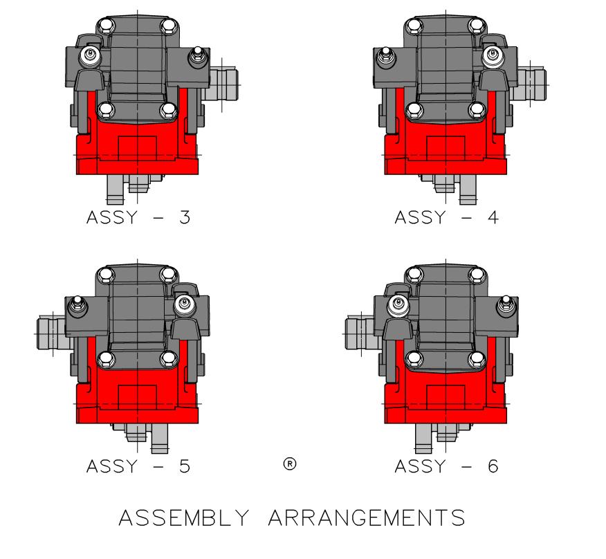
4 Rules of Conversion 4 Observe and make notes. Observe and note the bearing cap position. The hub of the output gear is positioned above the input gear. Observe and note the position of the shift fork. The bearing shims are on the same side as the ratio gear. Observe and note the assembly arrangement position. Ratio gear tooth round faces the output gear not the input gear. Do not reuse snap rings. Torque shift cover and bearing cap bolts o Lbs. ft. o N.m. Torque idler shaft retainer o In. Lbs. o N.m. Roll input gear o No side to side sloppiness o P.T.O. Case should not left off the bench Output shaft o Should turn by hand. o In and out play at least.001 no more than.005 for best bearing end play.


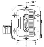
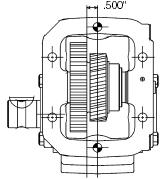
5 Rules of Conversion Observe and make notes. Observe and note the bearing cap position. Note relation of closed end bearing cap arrow to ratio letters on housing. Note and mark output flange (open end) to correct ratio on housing. Closed End Open End 5 Gear Ratios

6 Rules of Conversion Observe and make notes. Observe that the hub of the output gear is positioned above the input gear. Output Gear Hub Input Gear 6

7 Rules of Conversion Observe and make notes. Observe and note the position of the shift fork. Shifter Fork Input Gear Output Gear Ratio Gear 7

8 Rules of Conversion Observe and make notes. Observe the bearing shims are on the same side as the ratio gear. Ratio Gear Shim 14-P-73-X Thrust Washer 31-P-102 8

9 Rules of Conversion Observe and make notes. Observe and note the assembly arrangement position. 9


10 Disassembly Shifter Cover Using a 1/2 socket remove the four bolts on the shifter cover. Remove the shifter cover and gasket. Inspect the condition of the gasket. 10


11 Disassembly Input Gear Section Remove the NWD plug from the idler shaft using a 3/16 hex wrench. Remove idler shaft while holding the input gear section. Remove complete input gear section. 11
 cap screws on the")


12 Disassembly Closed End Remove the four (4) cap screws on the closed end bearing cap using a 1/2 hex wrench. Remove the bearing cap and gaskets. Inspect condition of gaskets and keep together. 12


13 Disassembly Closed End Bearing Removal Using a bearing puller set, remove the closed end bearing from the output shaft. Remove snap ring on the output shaft. DO NOT REUSE. 13


14 Caution and Reminder CAUTION: Never reuse a snap ring. Once it has been stretched it will not return to its original size. 14


15 Disassembly Output (Open) End Using a 1/2 hex wrench remove the four (4) open end hex head cap screws. Remove the output shaft and gear from the P.T.O. housing. Inspect gear and shaft for any nicks or wear. 15

16 Assembly 3 Arrangement 5 Arrangement 16


17 Assembly Output Section 3 Assembly Arrangement Make sure the output gear matches the correct assembly arrangement of the P.T.O. The output gear shift hub is positioned above the Input gear in the engaged position. Slide output shaft into housing and slide output gear onto the shaft. U, W & X ratios will slide through the opening as an assembly. 17


18 Assembly Output Section 3 Assembly Arrangement Using a snap ring slide or snap ring pliers install the snap ring onto the shaft. Make sure that the snap ring is seated into the groove on the output shaft. Install bearing onto closed end. REMINDER: Make sure the bearing is seated against the snap ring. Forgetting to do this can affect shaft end play. 18


19 Assembly Output Section 3 Assembly Arrangement Install gaskets. Install closed end bearing cap. Make sure the off set of the bearing cap is positioned correctly for the P.T.O. ratio. Using 1/2 hex wrench tighten and torque cap screws to Lbs. ft. [33-38 N.m.]. NOTE: Always use a crossing pattern when tightening bolts. 19

20 Assembly Output Section 3 Assembly Arrangement Make sure the off set of the bearing cap is positioned correctly for the P.T.O. ratio. NOTE: The narrow portion of the open end bearing cap matches the position of the arrow on the closed cap. 20


![[ 33-38 N.m.].](/docs-images/85/91369243/images/21-2.jpg "NOTE: Always use a crossing pattern when tightening the")
21 Assembly Output Section 3 Assembly Arrangement Using a seal slide. Install gaskets and open end cap/pump flange onto housing. Tighten and torque fasteners Lbs. ft. [ N.m.]. NOTE: Always use a crossing pattern when tightening the bolts. Check end play is set correctly between Can I turn the shaft by hand? 21
22 Assembly Ratio and Input Gear One Piece Input Gear Two Piece Input Gear Ratio Gear Snap Ring 22

23 Assembly Ratio and Input Gear Ratio Gear Input Gear Place the ratio gear on the splined surface of the input gear. NOTE: The rounded edge of the ratio gear should be away from the input gear. Snap Ring 23


24 Assembly Ratio and Input Gear Snap Ring Groove Snap Ring Slide Use a snap ring slide and driver or snap ring pliers to install the snap ring in the groove of the input gear. NOTE: Be careful to not over stretch the snap ring. 24


25 Assembly of Gear into Housing A = Input Gear B = Ratio Gear C = Output Gear Insert the thrust washer next to the input gear; place bearing shim on the same side as the ratio gear. NOTE: Tabs on washer and shims are placed in pocket on housing. Thrust Washer Shim 25


26 Assembly Input Section 3 Assembly Arrangement Note position of output gear in the engaged position. Shifter hub should be over P.T.O. input gear. Using a idler guide tool, insert complete input section into housing. No end to end play on output section. Gear turns freely. 26


27 Assembly Input Section 3 Assembly Arrangement Install O-Ring on idler shaft; be careful not to nick or cut the O-Ring. Slide the notched end of the shaft into the housing, aligning notch with roll pin. Install NWD plug on idler shaft and torque: In. Lbs. ( N.m.). Idler Shaft Notch O-Ring NOTE: Line on Idler Pin 27


28 Assembly Shifter Section 3 Assembly Arrangement Position output gear in the disengaged position. Position gasket and shift cover onto the P.T.O. housing. Slide the shift block or fork onto the hub of the output gear. Install capscrews and torque (16-20 Lbs. ft. [22 27 N.m.]) Do not over tighten you can break the shift cover or housing. Last function test the shifter and indicator switch. (80-90 PSI) 28

29 Final Steps Place P.T.O. on flat surface and spin the input gear. Gear should spin without lifting up housing. 29


30 Final Check Re-label P.T.O. All bolts and cap screws proper torque Testing o Function test shifter o Test indicator switch o Check end play of output shaft o Check input gear bearings Ready to install 30
31 Torque Specifications 442 Family Location Torque (English) Torque (Metric) NWD Plug In. Lbs N.m. Bearing Cap Open Lbs. ft N.m. Bearing Cap Pump Flange Lbs. ft N.m. Rotatable Flanges GA, GB, PA, PF, RA, RB, RE & RF ( ) (Qty. 3) RC, RD, RH ( ) (Qty. 6) RJ (Qty. 6), RY (Qty. 3) ( ) Lbs. ft N.m Lbs. ft N.m Lbs. ft N.m. Bearing Cap Closed Lbs. ft N.m. Shift Covers Lbs. ft N.m. 31
32 Corrected Torque with a Plus Dimension When using a torque wrench adapter which changes the distance from the torque drive to the adapter drive, apply the following formula to obtain torque rating. T = Actual (desired) torque Y = Apparent (indicated) torque L = Effective length lever E = Effective length of extension Adapter Drive Centerline Torque Wrench Wrench Drive Centerline Handgrip Centerline (Predetermined) Short Open End Adapters Set Screw Adapter FORMULA: T x L L + E = Y E L Hose Clamp Adapter 32
33 Corrected Torque with a Minus Dimension When using a torque wrench adapter which changes the distance from the torque drive to the adapter drive apply the following formula to obtain torque rating. T = Actual (desired) torque Y = Apparent (indicated) torque L = Effective length lever E = Effective length of extension Open End Wrench Adapter Wrench Drive Centerline Flare Nut Wrench Adapter Torque Wrench Adapter Drive Centerline Handgrip Centerline (Predetermined) Spanner Wrench Adapter FORMULA: T x L L - E = Y E L 33
34 34
Chelsea Kit Program May 6, 2011
 Chelsea Kit Program May 6, 2011 What is the KIT program? The Kit program provides you certain PTO s less the input gear or shift cover. It s purpose is to provide you with improved product coverage. Lowers
DISASSEMBLY AND ASSEMBLY
 205-03-1 Front Drive Axle/Differential Ford 8.8-Inch Ring Gear 205-03-1 DISASSEMBLY AND ASSEMBLY Axle Front Drive Special Tool(s) 2-Jaw Puller 205-D072 (D97L-4221-A) Special Tool(s) Carrier Bearing Replacer
Transmission Overhaul Procedures-Bench Service
 How to Assemble the Lower Reverse Idler Gear Assembly Special Instructions In 1996 Eaton changed the reverse idler system design. In the nut design, the reverse idler bearing was lubricated through a hole
Model 4360 Teardown and Reassembly Instructions
 Clean the outside surface of the transaxle. Place the shifter in neutral position. Remove detent cover screw (item 3), detent cover (item 4), detent springs (item 5), and detent balls (item 6). Use a magnet
1999 F-150/250 Workshop Manual
 Page 1 of 30 SECTION 205-03: Front Drive Axle/Differential Ford 8.8-Inch Ring Gear 1999 F-150/250 Workshop Manual DISASSEMBLY AND ASSEMBLY Procedure revision date: 01/08/2003 Axle Front Drive Special Tool(s)
parts list and service manual
 CS0 & CS Series clutch shift pto parts list and service manual U.S. Pat.,2,0 for the allison world transmission CS0 & CS Series Clutch shift PTO Exploded View parts list and description item qty part number
MANUAL TRANS OVERHAUL - BORG-WARNER - T56 6-SPEED MANUAL TRANSMISSIONS Borg-Warner T56 (MM6) 6-Speed
 6-Speed") IDENTIFICATION MANUAL TRANS OVERHAUL - BORG-WARNER - T56 6-SPEED 1998 MANUAL TRANSMISSIONS Borg-Warner T56 (MM6) 6-Speed Transmission has 2 identification labels, located on lower left side of case. One
IDENTIFICATION MANUAL TRANS OVERHAUL - BORG-WARNER - T56 6-SPEED 1998 MANUAL TRANSMISSIONS Borg-Warner T56 (MM6) 6-Speed Transmission has 2 identification labels, located on lower left side of case. One
3.2 DRIVE TORQUE HUB. Roll, Leak and Brake Testing SECTION 3 - CHASSIS & TURNTABLE. 3-2 JLG Lift
 3.2 DRIVE TORQUE HUB Roll, Leak and Brake Testing 10 LUG PATTERN Torque-Hub units should always be roll and leak tested before disassembly and after assembly to make sure that the unit's gears, bearings
DISASSEMBLY AND ASSEMBLY (Continued)
") 205-03-23 Front Drive Axle/Differential Ford 8.8-Inch Ring Gear 205-03-23 49. Measure the ring gear backlash at four places to obtain a consistent reading. 1 Mount the special tools on the indicator base.
205-03-23 Front Drive Axle/Differential Ford 8.8-Inch Ring Gear 205-03-23 49. Measure the ring gear backlash at four places to obtain a consistent reading. 1 Mount the special tools on the indicator base.
ADVANCE ADAPTERS INC. Fixed Yoke kit (S.Y.E. Kit)
") ADVANCE ADAPTERS INC. Fixed Yoke kit (S.Y.E. Kit) Instruction Sheet P/N: 50-7905 & 50-7906 KIT CONSISTS OF: No. Qty Part No. Description 1. 1 51-7906 TAILHOUSING, DIECAST 2. 1 52-7905 SHAFT, MAIN OUTPUT
ADVANCE ADAPTERS INC. Fixed Yoke kit (S.Y.E. Kit) Instruction Sheet P/N: 50-7905 & 50-7906 KIT CONSISTS OF: No. Qty Part No. Description 1. 1 51-7906 TAILHOUSING, DIECAST 2. 1 52-7905 SHAFT, MAIN OUTPUT
INSTRUCTIONS. Disassembly. Shifter Cam Assembly. Shifter Forks
 INSTRUCTIONS Disassembly To protect against accidental start-up of vehicle, always disconnect the negative battery cable before working on the motorcycle. Failure to disconnect the battery cable could
PARTS LIST AND SERVICE MANUAL
 CD40 SERIES PTO PARTS LIST AND SERVICE MANUAL HEAVY DUTY, CONSTANT DRIVE PTO FOR THE ALLISON WORLD TRANSMISSION CD40 SERIES CONSTANT DRIVE PTO EXPLODED VIEW CD40 COVER DETAIL (Backside) PTO ASSEMBLY ARRANGEMENTS
FA6B Series PTO PARTS LIST AND SERVICE MANUAL. Muncie Power Products, Inc.
 FAB Series PTO PARTS LIST AND SERVICE MANUAL Muncie Power Products, Inc. FAB PTO EXPLODED VIEWS Detail A Detail B Detail F Detail C Detail E Detail D Detail A Output Shaft Assembly 5 9 5 8 0 Detail AA
CS24/25 SERIES CLUTCH SHIFT PTO
 CS/ SERIES CLUTCH SHIFT PTO PARTS LIST AND SERVICE MANUAL Muncie Power Products, Inc. CS/ PTO EXPLODED VIEWS Detail B Detail A Detail E Detail C Detail D DETAIL A OUTPUT SHAFT ASSEMBLY 7 CS/ STANDARD OUTPUT
82 SERIES PTO PARTS LIST AND SERVICE MANUAL
 82 SERIES PTO PARTS LIST AND SERVICE MANUAL Muncie Power Products, Inc. 18 ft.lbs. (use 242 Loctite) 82 SERIES PTO EXPLODED VIEW 16 ft.lbs. 10 ft.lbs. (use 242 Loctite) 18 ft.lbs. 45 ft.lbs. (use 242 Loctite)
1989 Jeep Cherokee. STEERING COLUMN' '1989 STEERING Jeep Steering Columns STEERING COLUMN STEERING Jeep Steering Columns
 STEERING COLUMN 1989 STEERING Jeep Steering Columns DESCRIPTION All models use collapsible steering columns. All columns have integral ignition switch and locking device. Optional tilt wheel is available
1994 Mitsubishi Eclipse GS
 APPLICATIONS CHRYSLER MOTORS MANUAL TRANS OVERHAUL - MITSUBISHI W5M & W6M SERIES MANUAL TRANSMISSIONS Mitsubishi W5M31, TRANSMISSION APPLICATIONS (CHRYSLER MOTORS) Vehicle Application Transmission Model
DISASSEMBLY. Transmission. 2. Remove the 4 clutch housing bolts. Separate the clutch housing from the transmission.
 308-03A-1 DISASSEMBLY Transmission 308-03A-1 Special Tool(s) Puller, Bearing 205-D064 (D84L-1123-A) or equivalent Remover/Installer, Front Wheel Hub 204-069 (T81P-1104-C) 2. Remove the 4 clutch housing
Muncie Power Products, Inc.
 A SERIES POWER TAKE-OFF PARTS LIST AND SERVICE MANUAL Muncie Power Products, Inc. EXPLODED VIEWS Detail C A SERIES PTO EXPLODED VIEWS Detail D Detail A Detail B DETAIL A IDLER SHAFT ASSEMBLY 4 5 DETAIL
InstalL Instructions. trail-creeper 4.70 transfer case gear kit ( KIT and KIT) kit contents
 kit contents") InstalL Instructions trail-creeper 4.70 transfer case gear kit (105000-1-KIT and 105001-1-KIT) kit contents 5356 PINE AVE FRESNO, CA 93727 USA TOLL FREE: 877.4X4.TOYS WORLDWIDE: 559.252.4950 WWW.TRAIL-GEAR.COM
InstalL Instructions trail-creeper 4.70 transfer case gear kit (105000-1-KIT and 105001-1-KIT) kit contents 5356 PINE AVE FRESNO, CA 93727 USA TOLL FREE: 877.4X4.TOYS WORLDWIDE: 559.252.4950 WWW.TRAIL-GEAR.COM
CS24/25 SERIES CLUTCH SHIFT PTO
 CS/ SERIES CLUTCH SHIFT PTO PARTS LIST AND SERVICE MANUAL Muncie Power Products, Inc. CS/ PTO EXPLODED VIEWS Detail B Detail A Detail E Detail C Detail D DETAIL A OUTPUT SHAFT ASSEMBLY 7 CS/ STANDARD OUTPUT
Repair Manual VW 02T gearbox. INA GearBOX
 Repair Manual VW 02T gearbox INA GearBOX Special tools Repair Manual for the VW 02T gearbox Drain the transmission fluid (arrow). Remove the gearbox from the vehicle in accordance with the vehicle manufacturer
Rekluse Motor Sports, Inc. The z-start Clutch. Husaberg ( )
") Rekluse Motor Sports, Inc. The z-start Clutch Husaberg (1989-2003) Installation Guide Copyright 2002-2004 Rekluse Motor Sports z-start Revision 3.000 RMS125 Husaberg 89-03 191-225 Manual Revision: 012805
Rekluse Motor Sports, Inc. The z-start Clutch Husaberg (1989-2003) Installation Guide Copyright 2002-2004 Rekluse Motor Sports z-start Revision 3.000 RMS125 Husaberg 89-03 191-225 Manual Revision: 012805
 Page 1 of 22 SECTION 307-01: Automatic Transaxle/Transmission 4R70E/4R75E ASSEMBLY Procedure revision date: 05/29/2009 Transmission Printable View (1554 KB) Special Tool(s) Air Test Plate, Transmission
LIMITED SLIP DIFFERENTIAL INSTALLATION
 Installation of the limited slip gear can be done with axle out of car or with car lifted to gain access from underneath. Refer to repair manual for proper lifting instructions if car is to be lifted.
DRIVE AXLE Volvo 960 DESCRIPTION & OPERATION AXLE IDENTIFICATION DRIVE AXLES Volvo Differentials & Axle Shafts
 DRIVE AXLE 1994 Volvo 960 1994 DRIVE AXLES Volvo Differentials & Axle Shafts 960 DESCRIPTION & OPERATION All 960 station wagon models use type 1041 rear axle assembly. All 960 4-door models use type 1045
MANUAL TRANSAXLE Return to Main Table of Contents
 MANUAL TRANSAXLE Return to Main Table of Contents GENERAL... 2 MANUAL TRANSAXLE CONTROL... 12 SHIFT LEVER ASSEMBLY... 14 MANUAL TRANSAXLE... 15 MANUAL TRANSAXLE ASSEMBLY... 17 FIFTH SPEED SYNCHRONIZER
Assembly. NOTE: Before beginning assembly, perform/inspect the following:
 Page 1 of 31 Home Account Contact ALLDATA Log Out Help DAN GRIMWOOD DAN GRIMWOOD00002 Select Vehicle New TSBs Technician's Reference Component Search: OK 1997 Ford Truck F 150 2WD Pickup V6-4.2L VIN 2
Twin Master Combine. Transmission & Gear Boxes Section 8. 2 Speed Transmission Transmission Gear Shift
 Twin Master Combine Transmission & Gear Boxes Section 2 Speed Transmission... 2-4 Transmission Gear Shift... 5-6 PTO Swivel Gear Box 107021... 7- Transition Auger Gear Box 107026... 9-10 Straw Chopper
CS41 SERIES CLUTCH SHIFT PTO
 CS41 SERIES CLUTCH SHIFT PTO PARTS LIST AND SERVICE MANUAL Patent #2004200334 Muncie Power Products, Inc. CS41 SERIES CLUTCH SHIFT PTO EXPLODED VIEW 46 2 MUNCIE POWER PRODUCTS, INC. PARTS LIST AND DESCRIPTION
Transmission Overhaul Procedures-Bench Service
 How to Install the Auxiliary Countershaft Assembly Special Instructions To make auxiliary section assembly easier, you can make an auxiliary section fixture out of a 2" x 12" piece of wood. 3' 1' 3" 4.56"
2005 Toyota RAV AUTOMATIC TRANSMISSIONS U240E & U241E Overhaul
 2001-05 AUTOMATIC TRANSMISSIONS U240E & U241E Overhaul APPLICATION CAUTION: Flush oil cooler and oil cooler lines prior to transaxle installation. Oil cooling system contamination may cause premature transaxle
ASSEMBLY. Transmission Automatic Transmission 5R44E and 5R55E. Special Tool(s)
") 307-01-1 Automatic Transmission 5R44E and 5R55E 307-01-1 ASSEMBLY Transmission Special Tool(s) Holding Fixture, Transmission 307-262 (T93T-77002-AH) Special Tool(s) Installer, Transmission Extension Housing
307-01-1 Automatic Transmission 5R44E and 5R55E 307-01-1 ASSEMBLY Transmission Special Tool(s) Holding Fixture, Transmission 307-262 (T93T-77002-AH) Special Tool(s) Installer, Transmission Extension Housing
2003 E-Series Workshop Manual
 Page 1 of 20 SECTION 307-01B: Automatic Transmission 4R70W 2003 E-Series Workshop Manual ASSEMBLY Procedure revision date: 04/27/2006 Transmission Printable View (1828 KB) Special Tool(s) Dial Indicator
TRANSMISSION 6.7 GENERAL HOME. See Figure The transmission is a five-speed constantmesh type housed in an extension of the crankcase.
 TRANSMISSION 6.7 GENERAL See Figure 6-45. The transmission is a five-speed constantmesh type housed in an extension of the crankcase. Mainshaft Neutral Mainshaft st Gear b06x6x Countershaft 4 Out 5 Countershaft
Rekluse Motor Sports. The z-start Clutch GAS GAS. 200, 250, and strokes. 400 and strokes
 Rekluse Motor Sports The z-start Clutch GAS GAS 200, 250, and 300 2-strokes 400 and 450 4-strokes Installation Guide Copyright 2002-2004 Rekluse Motor Sports z-start Revision 3.000 RMS100 Gas Gas z-start
NP231 SHORT SHAFT "FIXED YOKE" KIT
 Page 1 of 11 KIT CONSISTS OF: No. Qty Part No. Description 1. 1 51-7905 TAILHOUSING, DIECAST 2. 1 52-7905 SHAFT, MAIN OUTPUT 3. 1 300474 SEAL WASHER, REAR YOKE 4 1 300475 YOKE, C.V. REAR 5. 1 300476 NUT,
23. Planetary Gear and Low Clutch S510212
 Automatic Transmission 23. Planetary Gear and Low Clutch S510212 A: REMOVAL S510212A18 1) Extract the torque converter clutch assembly. 2) Remove
ADVANCE ADAPTERS INC. P/N: NP231 SHORT SHAFT "FIXED YOKE" KIT
 Paso Robles, CA 93447 PAGE 1 OF 10 Telephone: (800) 350-2223 Fax: (805) 238-4201 Page Rev. Date: 06-24-02 KIT CONSISTS OF: No. Qty Part No. Description 1. 1 51-7906 TAILHOUSING, DIECAST 2. 1 52-7905 SHAFT,
AUTOMATIC TRANSMISSIONS Mitsubishi F3A20 Series TRANSMISSION APPLICATION TABLE
 Article Text ARTICLE BEGINNING AUTOMATIC TRANSMISSIONS Mitsubishi F3A20 Series APPLICATION TRANSMISSION APPLICATION TABLE Vehicle Application Transmission Model Colt 3-Speed (1990-94)... F3A21 Colt Vista
Muncie Power Products, Inc.
 SH6 & SH8 SERIES POWER TAKE-OFF PARTS LIST AND SERVICE MANUAL Muncie Power Products, Inc. SH6 & SH8 SERIES PTO EXPLODED VIEW PTO ASSEMBLY ARRANGEMENTS NO. 1 ASSEMBLY NO..3 ASSEMBLY 25 ft.lbs. 35 ft.lbs.
TRANSMISSION 6.7 GENERAL HOME. See Figure The transmission is a five-speed constantmesh type housed in an extension of the crankcase.
 TRANSMISSION 6.7 GENERAL See Figure 6-46. The transmission is a five-speed constantmesh type housed in an extension of the crankcase. b06x6x Neutral st Gear Mainshaft Mainshaft 4 5 4 5 Countershaft Out
ASSEMBLY. Transmission Automatic Transaxle/Transmission. Special Tool(s) Alignment Set, Fluid Pump 307-S039 (T74P X) Special Tool(s)
 Alignment Set, Fluid Pump 307-S039 (T74P X) Special Tool(s)") 307-01-1 Automatic Transaxle/Transmission 307-01-1 ASSEMBLY Transmission Special Tool(s) Adjustment Set, Transmission Band 307-S022 (T71P-77370-A) Special Tool(s) Alignment Set, Fluid Pump 307-S039 (T74P-77103-X)
307-01-1 Automatic Transaxle/Transmission 307-01-1 ASSEMBLY Transmission Special Tool(s) Adjustment Set, Transmission Band 307-S022 (T71P-77370-A) Special Tool(s) Alignment Set, Fluid Pump 307-S039 (T74P-77103-X)
Max IV Rear Axle Replacement For models after Serial Number and all rear splined axle replacements.
 Max IV Rear Axle Replacement For models after Serial Number 19089 and all rear splined axle replacements. 10/8/03 Max IV Snap Ring Rear Axle replacement.doc Tools required: 9/16 Wrench 6 Extension Steel
CHAPTER 15 WINCH MAINTENANCE. This chapter contains maintenance instructions for disassembly and repair of winch components at the Direct
 CHAPTER 15 WINCH MAINTENANCE This chapter contains maintenance instructions for disassembly and repair of winch components at the Direct 15-1. INTRODUCTION Support maintenance level. Some subassemblies
Fig Variable Speed Valve Parts
 5 DISASSEMBLY OF VARIABLE SPEED CONTROL VALVE (Seal Replacement with Control Valve in the Bobcat). Remove seat and seat plate (Fig. ).. Remove variable speed control lever linkage rod. 3. Remove temperature
DANA 300 T/C 32 SPLINE OUTPUT WITHOUT YOKE
 KIT CONSISTS OF: No. Qty Part No. Description P.O. Box 247, 4320 Aerotech Center Way PAGE 1 OF 6 Page Rev. Date: 04-18-17 1. 1 300491 REAR YOKE END PLAY SHIM (3 sizes) (Installed by AA) 2. 1 300513 BEARING,
NP231 SHORT SHAFT "FIXED YOKE" KIT FOR NON-CV YOKES AND FLANGE YOKES
 KIT CONSISTS OF: No. Qty Part No. Description 1. 1 51-7906 TAILHOUSING, DIECAST 2. 1 52-7905 SHAFT, MAIN OUTPUT 3. 1 300474 SEAL WASHER, REAR YOKE 4. 1 300476 NUT, REAR YOKE 5. 1 300480 SEAL WASHER, FRONT
Second Stage Regulator - 1/4 Turn
 Second Stage Regulator - 1/4 Turn MAINTENANCE AND REPAIR TAL 806 (L) Rev. 6 MSA 2008 Prnt. Spec. 10000005389 (I) Mat. 10042827 Doc. 10000015245 1/4 TURN SECOND STAGE REGULATOR SECOND STAGE REGULATOR COMPONENTS
Installation Instructions INDY SHIFTER Fits: Mustang Fastback & Convertible with MT-82 Transmission Catalog #
 Installation Instructions INDY SHIFTER Fits: 2015-2018 Mustang Fastback & Convertible with MT-82 Transmission Catalog # 3916036 Watch our installation video on YouTube WORK SAFELY! For maximum safety,
1. General Description
 1. General Description A: SPECIFICATION 1. MANUAL TRANSMISSION AND FRONT DIFFERENTIAL Type Transmission gear ratio Front reduction gear Rear reduction gear Front differential Center differential Final
SISU DP-330 DRIVE GEAR. Maintenance Manual
 SISU DP-330 DRIVE GEAR Maintenance Manual Sisu Axles, Inc. Autotehtaantie 1 PO Box 189 Fin-13101 Hameenlinna Finland Phone +358 204 55 2999 Fax +358 204 55 2900 DP330DG.PDF (3/2007) TABLE OF CONTENTS
Maintenance Manual MM-0194 Single reduction leading axle carrier for tandem axle series MD61. Revised September 2017
 Maintenance Manual MM-0194 Single reduction leading axle carrier for tandem axle series MD61 Revised September 2017 Service Notes Before You Begin This publication provides installation and maintenance
TC20 Chain Driven Power Take-Off Overhaul Instructions
 TC20 Chain Driven Power Take-Off Overhaul Instructions Table of Contents Section Page Introduction 4 Ordering Repair Parts 4 General Information 5 Special Tools 6 Disassembly See Page 2 Reassembly See
BRAKE SYSTEM Toyota Celica DESCRIPTION DRUM BRAKES ADJUSTMENTS BRAKE PEDAL HEIGHT ADJUSTMENTS BRAKE PEDAL FREE PLAY ADJUSTMENTS
 BRAKE SYSTEM 1988 Toyota Celica 1988-89 BRAKES Toyota Celica, Corolla, MR2, Tercel DESCRIPTION The hydraulic brake system uses a tandem master cylinder with a vacuum power assist servo. MR2 and some Celica
TL (TIL03029) REPAIR MANUAL. Telma model FN72-40 replacement on Arvin Meritor forward tandem carrier. Page 1 of JUL-11.
 REPAIR MANUAL. Telma model FN72-40 replacement on Arvin Meritor forward tandem carrier. Page 1 of JUL-11.") REPAIR MANUAL Telma model FN72-40 replacement on Arvin Meritor forward tandem carrier Page 1 of 10 29-JUL-11 Exploded view P/N: FE962100 Stator Carrier Kit Includes: Qty Description Telma P/N 1 Stator
REPAIR MANUAL Telma model FN72-40 replacement on Arvin Meritor forward tandem carrier Page 1 of 10 29-JUL-11 Exploded view P/N: FE962100 Stator Carrier Kit Includes: Qty Description Telma P/N 1 Stator
FR6Q PTO PARTS LIST AND SERVICE MANUAL. Muncie Power Products, Inc.
 FR6Q PTO PARTS LIST AND SERVICE MANUAL Muncie Power Products, Inc. MODEL NUMBER CONSTRUCTION FR6Q - F1 09-6 N X Model: FR6Q Ford 6-Bolt Quiet Transmission Gear: F1 Ford 6R10 Internal Gear Ratio: 09 0.90:1
Yukon Gear & Axle D30, D44 & GM 8.5" Hardcore Locking Hub Installation Guide
 Yukon Gear & Axle D30, D44 & GM 8.5" Hardcore Locking Hub Installation Guide PLEASE READ COMPLETELY BEFORE INSTALLATION Application Guide: YHC70005 D30 & D44 30spl - YA WU-08 Spin Free - D30, 30 spline
MANUAL TRANSMISSIONS Mitsubishi F4M20, F5M20, F5M30 & KM200 Series TRANSMISSION APPLICATION
 Article Text ARTICLE BEGINNING MANUAL TRANSMISSIONS Mitsubishi F4M20, F5M20, F5M30 & KM200 Series APPLICATION TRANSMISSION APPLICATION Vehicle Application Transmission Model Chrysler Motors (2WD) 4-Speed
3M Overhaul Service Kit
 SERVICE INSTRUCTIONS FOR 3M 12,000 RPM 5 in. (127 mm) and 6 in. (150 mm) RANDOM ORBITAL SANDERS 3M Overhaul Service Kit The part number 20347, 3M Overhaul Service Kit, contains all the replacement parts
SATURN OVERDRIVE ASSEMBLY
 KIT CONSISTS OF: No. Qty Part No. Description P.O. Box 247, 4320 Aerotech Center Way Paso Robles, CA 93447 Telephone: (800) 350-2223 Fax: (805) 238-4201 PAGE 1 OF 11 Page Rev. Date: 07-26-18 P/N: SATURN
INSTRUCTION MANUAL AND PARTS LIST FOR. (A)E3LB(C)(K)-187, -200, and -250 SERIES PUMPS
E3LB(C)(K)-187, -200, and -250 SERIES PUMPS") INSTRUCTION MANUAL AND PARTS LIST FOR (A)E3LB(C)(K)-187, -200, and -250 SERIES PUMPS WARNING This Manual and GENERAL INSTRUCTIONS MANUAL, SRM00046, should be read thoroughly prior to pump installation,
INSTRUCTION MANUAL AND PARTS LIST FOR (A)E3LB(C)(K)-187, -200, and -250 SERIES PUMPS WARNING This Manual and GENERAL INSTRUCTIONS MANUAL, SRM00046, should be read thoroughly prior to pump installation,
Steer Axles. Spicer. Service Manual. AXSM-0070 November Front Drive Steer Axle Model 60
 Spicer Steer Axles Service Manual AXSM-0070 November 2017 Front Drive Steer Axle Model 60 General Information The description and specifications contained in this service publication are current at the
2001 F-650/750 Workshop Manual
 26. Pack the reverse idler gear bearings with lubricant. Use Moly number 2 lubricant or equivalent. 27. Install the following: 1. Assemble the reverse idler gear and bearings onto the idler shaft. 2. Position
Rebuild/Repack Kits for Flowrite VF 599 Series 2-1/2 to 6-inch Valves
 Document No. 129-216 Rebuild/Repack Kits for Flowrite VF 599 Series 2-1/2 to 6-inch Valves Product Description This kit contains the parts necessary to rebuild and repack either the normal duty or high
Repair Manual VW 02J gearbox. INA GearBOX
 Repair Manual VW 02J gearbox INA GearBOX Special tools Pipe section, 50 mm: Press fitting of synchronizer body for third/fourth gear. Assembly of support bearing for input and output shaft. Part number:
STERNDRIVE UNIT 3 A DRIVE SHAFT HOUSING
 STERNDRIVE UNIT 3 A 23262 DRIVE SHAFT HOUSING Table of Contents Page Specifications............................ 3A-1 Torque Specifications.................. 3A-1 Upper Drive Shaft Bearing Preload.......
SECTION B Manual Transaxle/Transmission TR6060
 308-03B-i Manual Transaxle/Transmission TR6060 308-03B-i SECTION 308-03B Manual Transaxle/Transmission TR6060 CONTENTS PAGE Transmission... 308-03B-2 308-03B-2 Manual Transaxle/Transmission TR6060 308-03B-2
DF 15. DIFFERENTIAL 1GR-FE FRONT DIFFERENTIAL CARRIER ASSEMBLY (for 4WD) REMOVAL
 REMOVAL") DIFFERENTIAL 1GR-FE FRONT DIFFERENTIAL CARRIER ASSEMBLY (for 4WD) 15 REMOVAL 1. REMOVE FRONT WHEELS 2. REMOVE REAR ENGINE UNDER COVER ASSEMBLY (a) Remove the 6 bolts and engine under cover assembly. 3.
DIFFERENTIAL 1GR-FE FRONT DIFFERENTIAL CARRIER ASSEMBLY (for 4WD) 15 REMOVAL 1. REMOVE FRONT WHEELS 2. REMOVE REAR ENGINE UNDER COVER ASSEMBLY (a) Remove the 6 bolts and engine under cover assembly. 3.
Transaxle. 1. Mount the transaxle to Bench Mounted Holding Fixture T57L-500-B.
 «1997 Aspire Table of Contents» «Group 07: TRANSAXLE» «Section 07-01: Transaxle, Automatic» «DISASSEMBLY» Transaxle CAUTION: To prevent dirt from entering the transaxle, it should be disassembled and kept
PARTS LIST AND SERVICE MANUAL
 CS0 & CS SERIES CLUTCH SHIFT PTO PARTS LIST AND SERVICE MANUAL Muncie Power Products, Inc. ft.lb. See Cover Detail To Trans. Port 3 33 CS0 SERIES PTO EXPLODED VIEW 3 0 9 3 9 3 3 ft.lb. 3 3b 9 3 ft.lb.
Steering. Table of Contents
 Steering Table of Contents Sub-Headings Safety 2 Warnings 2 s 2 s 2 Introduction 2 Description of Service Manual 2 General Design 2 Removal of Steering Wheel and Column 2 Steering Column Removal 3 Steering
26 Hume Reserve Court, Nth. Geelong, 3215 Phone: (03) Fax: (03) INSTALLATION MANUAL. for
 Fax: (03) INSTALLATION MANUAL. for") 26 Hume Reserve Court, Nth. Geelong, 3215 Phone: (03) 5272 2844 Fax: (03) 5272 2633 GEARLESS CENTRE DIFFERENTIAL FULL-TIME 4X4 TRANSFER CASE CONVERSION DEDICATED LOW RANGE INSTALLATION MANUAL for TOYOTA
26 Hume Reserve Court, Nth. Geelong, 3215 Phone: (03) 5272 2844 Fax: (03) 5272 2633 GEARLESS CENTRE DIFFERENTIAL FULL-TIME 4X4 TRANSFER CASE CONVERSION DEDICATED LOW RANGE INSTALLATION MANUAL for TOYOTA
Transmission, disassembling and assembling
 Page 1 of 27 34-43 Transmission, disassembling and assembling Disassembly sequence Page 34-55. Transmission overview 1-1st gear 2-2nd gear 3-3rd gear 4-4th gear 5-5th gear 6 - Reverse gear Removing and
3M Overhaul Service Kit
 SERVICE INSTRUCTIONS FOR 3M 12,000 RPM 3 in. (77 mm) RANDOM ORBITAL SANDERS 3M Overhaul Service Kit The part number 20346, 3M Overhaul Service Kit, contains all the replacement parts that naturally wear
Compressor - Install (E.40.C.31 - F.10.A.15)
") Compressor - Install (E.40.C.31 - F.10.A.15) 1. Set the compressor on its mount and secure into place using the four bolts. Connect the refrigerant suction line (5) and the discharge line (4). Install
Compressor - Install (E.40.C.31 - F.10.A.15) 1. Set the compressor on its mount and secure into place using the four bolts. Connect the refrigerant suction line (5) and the discharge line (4). Install
 Page 1 of 15 Transmission, Model S5-42 ZF Model S5-42 ZF Disassembly NOTE: For 4x4 and F-Super Duty vehicles, skip to Step 5. 1. Attach the transmission to the Bench Mounted Holding Fixture T57L-500-B
Rekluse Motor Sports. The z-start Clutch CRF 250X. Installation Guide Copyright 2002 Rekluse Motor Sports z-start Revision RMS116 CRF 250X
 Rekluse Motor Sports The z-start Clutch CRF 250X Installation Guide Copyright 2002 Rekluse Motor Sports z-start Revision 3.000 RMS116 CRF 250X 191-216 Manual Revision: 103105 Rekluse Motor Sports, inc.
1920 & 2120 Compact Tractors Volume 1 of 2
 Ford Service Manual 1920 & 2120 Compact Tractors Volume 1 of 2 Service Manual THIS IS A MANUAL PRODUCED BY JENSALES INC. WITHOUT THE AUTHORIZATION OF FORD OR IT S SUCCESSORS. FORD AND IT S SUCCESSORS ARE
Ilustrated Parts List
 Spicer Drive Axles Ilustrated Parts List Spicer All Wheel 4 x 4 Drive System AXIP-0400 November 1999 Page to Insert The Spicer 4x4 Drive System Axle models and other equipment covered in this publication
FA SERIES FORD AUTOMATIC PTO
 FA SERIES FORD AUTOMATIC PTO PARTS LIST AND SERVICE MANUAL Muncie Power Products, Inc. FA SERIES PTO EXPLODED 18 Ft.Lb. 5 Ft.Lb. 18-25 Ft.Lb. Gasket Ford Supplied 44 Reuse Gasket Found on Opening or Order
REPAIR INSTRUCTIONS - ON VEHICLE
 2013 TRANSMISSION Automatic Transmission - 6T40 - Repair Instructions - On Vehicle - Orlando REPAIR INSTRUCTIONS - ON VEHICLE MANUAL SHIFT DETENT LEVER WITH SHAFT POSITION SWITCH ASSEMBLY REPLACEMENT Special
PROPELLER SHAFT & DIFFERENTIAL CARRIER SECTIONPD CONTENTS
 PROPELLER SHAFT & DIFFERENTIAL CARRIER SECTIONPD CONTENTS PREPARATION...2 PROPELLER SHAFT...5 On-Vehicle Service...6 Removal and Installation...7 Inspection...7 Disassembly...7 Assembly...8 ON-VEHICLE
SECTION Front Drive Axle/Differential
 205-03-i Front Drive Axle/Differential 205-03-i SECTION 205-03 Front Drive Axle/Differential CONTENTS PAGE Axle... 205-03-2 205-03-2 Front Drive Axle/Differential 205-03-2 Axle Special Tool(s) C-Frame
MANUAL TRANSMISSION MUA 5C (4X2, 4X4) AND TREMEC T5R(4X2)
 AND TREMEC T5R(4X2)") MANUAL TRANSMISSION 7B 1 RODEO TRANSMISSION MANUAL TRANSMISSION MUA 5C (4X2, 4X4) AND TREMEC T5R(4X2) CONTENTS Service Precaution...................... 7B 2 General Description..................... 7B
MANUAL TRANSMISSION 7B 1 RODEO TRANSMISSION MANUAL TRANSMISSION MUA 5C (4X2, 4X4) AND TREMEC T5R(4X2) CONTENTS Service Precaution...................... 7B 2 General Description..................... 7B
EATON 751, 781 HYDROSATIC TRANSAXLE
 EATON 751, 781 HYDROSATIC TRANSAXLE Table Of Contents Page 1 of 1 751, 851, 771, AND 781 HYDROSTATIC TRANSAXLE TRANSAXLES 751, 851 TRANSAXLE WITH CHARGE PUMP 781 SERIES HYDROSTATIC TRANSAXLE AXLE HOUSING
70001 and Clutch Rebuild Instructions
 70001 and 70010 Clutch Rebuild Instructions Brinn, Incorporated 1615 Tech Drive Bay City, MI 48706 Telephone 989.686.8920 Fax 989.686.6520 www.brinninc.com Notice Use these instructions if you only want
Repair Manual Ford DPS6 Gearbox. INA GearBOX
 Repair Manual Ford DPS6 Gearbox INA GearBOX Special Tools Tool kit (400 0477 10) for professional repair of the Ford DPS6 gearbox. Assembly table: Table (A) for securing the shafts, gear shift positions
INSTALLATION INSTRUCTIONS ASSEMBLY & DISASSEMBLY
 8405/6ASERIES PTO INSTALLATION INSTRUCTIONS ASSEMBLY & DISASSEMBLY 8405/6A DISASSEMBLY-REASSEMBLY INSTRUCTIONS This document contains the information to properly disassemble/reassembleyour 8405/6A Series
SERVICE MANUAL MODEL FRONT CARRIER TYPE
 SPICER AXLE SERVICE MANUAL MODEL FRONT CARRIER TYPE INDEX Page LUBRICATION... 3 SPECIAL SERVICE TOOLS...................................................... 4 AXLE IDENTIFICATION... 5 SHAFT BEARINGS AND
26 Hume Reserve Court, Nth. Geelong, 3215 Phone: (03) Fax: (03) DUAL RANGE HIGH SPEED INSTALLATION MANUAL. for
 Fax: (03) DUAL RANGE HIGH SPEED INSTALLATION MANUAL. for") 26 Hume Reserve Court, Nth. Geelong, 3215 Phone: (03) 5272 2844 Fax: (03) 5272 2633 GEARLESS CENTRE DIFFERENTIAL FULL-TIME 4X4 TRANSFER CASE CONVERSION DUAL RANGE HIGH SPEED INSTALLATION MANUAL for TOYOTA
26 Hume Reserve Court, Nth. Geelong, 3215 Phone: (03) 5272 2844 Fax: (03) 5272 2633 GEARLESS CENTRE DIFFERENTIAL FULL-TIME 4X4 TRANSFER CASE CONVERSION DUAL RANGE HIGH SPEED INSTALLATION MANUAL for TOYOTA
BRAKE SYSTEM Nissan 240SX DESCRIPTION BRAKE BLEEDING * PLEASE READ FIRST * BLEEDING PROCEDURES ADJUSTMENTS BRAKE PEDAL HEIGHT SPECS TABLE
 BRAKE SYSTEM 1990 Nissan 240SX 1990 BRAKE SYSTEMS Nissan Disc & Drum Axxess, Maxima, Pathfinder, Pickup, Pulsar NX, Sentra, Stanza, 240SX, 300ZX DESCRIPTION All brake systems are hydraulically operated
Rekluse Motor Sports. The z-start Clutch LTR 450. Installation Guide Copyright 2002 Rekluse Motor Sports z-start Revision 3.
 Rekluse Motor Sports The z-start Clutch LTR 450 Installation Guide Copyright 2002 Rekluse Motor Sports z-start Revision 3.000 RMS166 LTR 450 191-266 Manual Revision: 032306 Rekluse Motor Sports, inc. 110
Installation Instructions
 Installation Instructions Rear Disc Brake Conversion Kit Item # RC2001, RC2001X Applications: Mopar 8-3/4 & 9-3/4 Rear Axles Thank you for choosing Leed Brakes for your automotive product needs. Before
Single-Reduction Forward Differential Carriers on Tandem and Tridem Axles
 Maintenance Manual 5L Single-Reduction Forward Differential Carriers on Tandem and Tridem Axles Revised 08-15 Service Notes About This Manual This manual provides maintenance and service information for
Installation Instructions
 Installation Instructions Rear Disc Brake Conversion Kit Item # RC1001, RC1001X Applications: 64-72 A-body, 67 F-Body, 63-67 X-body with Non Staggered Shocks Thank you for choosing GPS Auto for your automotive
Further information: Phone: Schaeffler Automotive Aftermarket
 Further information: www.repxpert.de Phone: +49 6103 753-333 www.schaeffler-aftermarket.de 999 6006 570_08.2015 2015 Schaeffler Automotive Aftermarket LuK repair solution for dry double clutches Disassembly
TAF 5-Speed Transmission Kit Instruction Manual
 TAF 5-Speed Transmission Kit Instruction Manual Item No. Super Touring Super Street Fits Monkey and Gorilla Frame Nos Z50J-13000172699999 AB27-10000011899999 Thank you for purchasing one of our products.
SPECIAL TOOLS Dodge Pickup 5.9L Eng R3500. Fig 1: Identifying Remover C-3985-B (Special Tool) 9/6/13 Printer Friendly View
 9/6/13 Printer Friendly View") Procedures 2003 Dodge Pickup 5.9L Eng R3500 manual transmission SPECIAL TOOLS Fig 1: Identifying Remover C-3985-B (Special Tool) www2.prodemand.com/print/index?content=tabs&module=true&tab=true&terms=true&ymms=false&classname=
Procedures 2003 Dodge Pickup 5.9L Eng R3500 manual transmission SPECIAL TOOLS Fig 1: Identifying Remover C-3985-B (Special Tool) www2.prodemand.com/print/index?content=tabs&module=true&tab=true&terms=true&ymms=false&classname=
Single-Reduction Forward Differential Carriers on Tandem and Tridem Axles
 Maintenance Manual 5L Single-Reduction Forward Differential Carriers on Tandem and Tridem Axles Revised 12-10 Service Notes About This Manual This manual provides maintenance and service information for