Power Wheel Model 9 Planetary Gear Drives
|
|
|
- Alicia Ellis
- 6 years ago
- Views:
Transcription


1 Power Wheel Model 9 Planetary Gear Drives AuburnGear.com


2 Model 9 Features & A Series Integral Brake Information... WHEEL DRIVES Standard Configurations with A Series Integral Parking Brake with N-Series Fully Integrated Parking Brake SHAFT DRIVES Standard Configurations with A Series Integral Parking Brake SPINDLE DRIVES Standard Configurations with A Series Integral Parking Brake SHAFT INPUT/ DRIVES Standard Configurations Output Shafts...0 INFORMATION Other Options...1 Lubrication Data... Warranty... Application Worksheet... Phone Web AuburnGear.com
3 Power Wheel Model 9 Features Large tapered roller bearings allow increased axial and radial loading. Double heat treat spindles provide toughness and increase fatigue life. High strength secondary casting helps resist shock loading. Ductile iron hubs provide added strength for resistance to impact loading. Optimized gear geometry increases the contact ratio, which enhances gear life. Bearing nut provides preload to optimize bearing life. Power Wheel Model 9 Features A Series Integral Parking Brake PISTON: Improved design for superior life at higher pressures High strength gear material allows greater power density and improves gear life. GENERAL A SERIES DATA: 1. Maximum operating pressure is,000 psi (06.4 Bar). Pressure spikes or surges not to exceed,500 psi (40.8 Bar). Surge pressure in excess of,500 psi (40.8 Bar) caused by spikes in the hydraulic system could shorten brake life and must be avoided.. Use only SAE grade 8 mounting bolts and torque to lb. ft. (108-1N-m) for motor mounting.. PRECAUTION: Bench testing may cause distortion of components or bolt failure. Mounting bolts must be used for supplemental clamping. 4. Minimum Release Pressure is defined as the hydraulic pressure required to obtain full running clearance. 5. Cubic Inch Displacement is the volume of oil required to release the brake piston 1.0 in (16.4cc) for a new brake and.0 in (.8cc) for a worn brake pack. FRICTION DISCS: Heavy Duty Graphtic Paper for wet sump applications. Characteristics: Superior energy capability, high and stable coefficient of friction and smooth engagement. BRAKE RATINGS MOUNT MODEL HOLDING TORQUE MIN. RELEASE PRESSURE STYLE SAE A & B B1 1,540 lb-in (174 N-m) 190 PSI (1.1 BAR) Short SAE A & B B 1,800 lb-in (0 N-m) 0 PSI (15.1 BAR) Short SAE A & B B,400 lb-in (71 N-m) 90 PSI (0.0 BAR) Short SAE B B4,400 lb-in (71 N-m) 160 PSI (11.0 BAR) Long SAE C B4,400 lb-in (71 N-m) 15 PSI (9. BAR) SAE A & B B5,00 lb-in (6 N-m) 0 PSI (15.1 BAR) Long SAE A & B B6,600 lb-in (407 N-m) 0 PSI (15.8 BAR) Long SAE C B6,600 lb-in (407 N-m) 185 PSI (1.7 BAR) SAE A & B B7 4,00 lb-in (475 N-m) 60 PSI (17.9 BAR) Long SAE C B7 4,00 lb-in (475 N-m) 10 PSI (14.5 BAR) Maximum Release Pressure,000 PSI (06.4 BAR) Auburn Gear LLC 400 East Auburn Drive Auburn, IN (USA)
4 Model 9 Wheel Drives - Double Reduction General Specifications Max. intermittent output torque 1,...10,000 lb-in (14,690 Nm) Max. input speed...5,000 RPM Power Wheel Approximate Weight lbs (94.kg) Approximate Oil capacity oz (1,685 cc) 1 Depending on the duty cycle and the nature of the application, a normal continuous output torque of 1/ to 1/ of the maximum intermittent should yield satisfactory Power Wheel life. Customer testing and application analysis is strongly recommended. If application exceeds published limits, contact Auburn Gear. For Lubrication Data, see Page Dimensions given in: INCHES (mm) SAE B, C (77. 1) 9.50 (41.0) ( ).7 (18.5) MAX. SHAFT LENGTH SAE B: (49.4) - 1T SAE C:.15 (56.5) - 1T SAE C:.545 (64.64) - 14T 1.45 (6.8) Min. 5.7 (16.4) 1.4 (1.4) Max..6 (57.4).76 (19.0) 8 Thru Holes ( ) Equally Spaced 10.6 (70.0) 1.75 (14.) 1.80 (50.5) Output O RING Rotation REQUIRED Opposite to O Ring Sizes: Input Rotation SAE B -155 SAE C -159 (Not supplied by Auburn Gear) 11.0 (79.9) (4.95) SEE MOUNTING CHART (9.7) 8 Thru Holes,.750 (19.05) 10 UNC B Equally Spaced - B1, B, C1, C 8 Thru Holes,.65 (15.88) 11 UNC B Equally Spaced - B, C Motor Mounting Holes.5 Offset from Spindle Holes - B1, B, B Motor Mounting Holes Inline with Spindle Holes - C1, C, C SAE B1, B, C1, C 4.1 (104.7) PREFERRED CENTER of WHEEL or LOAD: 1.01 (5.7).96 (4.4) 10 Thru Holes ( ) Equally Spaced Stud Length Wheel Stud Detail Note that the stud lengths shown in the feature chart represent the total length of the stud under the head. NON-POWERED UNITS ARE ALSO AVAILABLE Contact Auburn Gear for Information 4 Phone Web AuburnGear.com
5 FEATURE CHART: MODEL 9 WHEEL DRIVES DOUBLE REDUCTION MOTOR PILOT/HUB INPUT SPLINE RATIO WHEEL STUDS SPECIAL FEATURES DESCRIPTION Select desired characteristics from chart, note correct order codes, and order using sample format shown at right: MAKE ALL SELECTIONS WITHIN ONE COLUMN ORDER CODES B1 9WB1 B 9WB B 9WB C1 9WC1 9WC1 C 9WC C 9WC 1T. 16 / 1 14T. 1 / T. 16 / : : :1 5.71: :1 0 USE OPTION ORDER CODES TO BUILD PART NUMBER 4.0: : : / 8 by / 4 by.76* 9 / 4 by.1* 11 9 / 16 by NONE 0 Brake Disc** D Boot Seal Z Z Brake Disc Holes Quick Disconnect Oil Plugs/ Spindle Side H.D. Multi-Lip Oil Seal * Not available with B or C mounting ** Customer supplied, Auburn Gear assembled DH Q P T MOTOR MOUNTING CHART MOTOR MOUNTING HOLE DIMENSIONS B1, B, B ().500 (1.70) -1 UNC. B Thd on (146.05) B. C.* C1, C, C (4).500 (1.70) - 1 UNC. B Thd on 6.75 (161.9) B. C.* 9WC Z DIAMETER ø ( ) ø ( ) * O RING OR GASKET REQUIRED (Not Supplied by Auburn Gear) O RING SIZES: SAE B 155, SAE C 159 The data presented in this catalog is for general information and preliminary layout purposes only. Auburn Gear, through its policy of continual improvement, reserves the right to update its products; therefore, the information presented is subject to change. For specific application and/or dimensional information, contact Auburn Gear. ALLOWABLE RADIAL LOAD LBS (KG) 0,000 (1,608) 5,000 (11,40) 0,000 (9,07) 15,000 (6,804) 10,000 (4,56) 5,000 (,68) -4 (-101.6) MAXIMUM LOAD LINE - (-76.) MODEL 9 BEARING LIFE CURVE Based On LIFE =,000 Hours B10 SPEED = 100 RPM Output - (-50.8) -1 (-5.4) 0 1 (5.4) Preferred Center of Load (50.8) 1.01 (5.65) B1, B, C1, C (76.).6 (57.4) B, C 4 (101.6) 5 (17.0) 6 (15.4) DISTANCE FROM MOUNTING FACE TO RADIAL LOAD INCHES (MM) These curves are supplied as a design guide and apply to resultant radial load only. They indicate the importance of maintaining wheel position over the bearing center. For actual analysis, applications should be reviewed by Auburn Gear Engineering using data supplied on Application Data Form. BEARING LOAD, LIFE AND SPEED RELATIONSHIPS SF x R LF = R R = Allowable resultant load for given location from mounting flange R = Anticipated load at location from mounting flange LF = Life Factor from table (see below) SF = Speed Factor from table (see below) BEARING SPEED HOURS (RPM) SF LF B-10 LIFE CAUTION: The same torsional loading constraints used in the driving mode must be used in the braking mode when braking through the Power Wheel drive gear set. Auburn Gear LLC 400 East Auburn Drive Auburn, IN (USA) 5
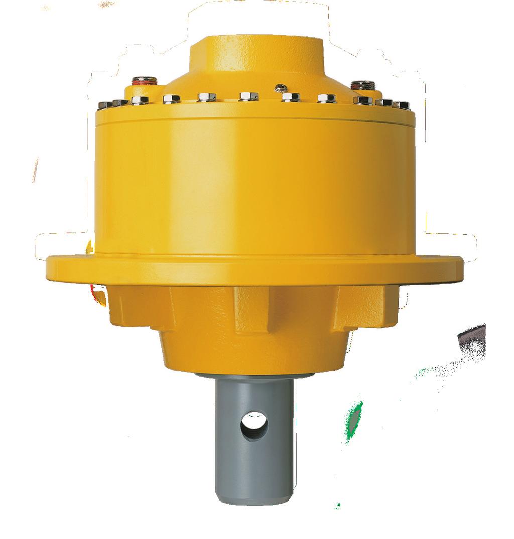
6 Power Wheel Model 9 Wheel Drives - Double Reduction with A Series Integral Parking Brake General Specifications Max. intermittent output torque 1,...10,000 lb-in (14,690 Nm) Max. input speed...,500 RPM Approximate Weight... 5 lbs (10kg) Approximate Oil capacity... 6 oz (1,85 cc) For Lubrication Data, see Page For Brake Data, see Page 1 Depending on the duty cycle and the nature of the application, a normal continuous output torque of 1/ to 1/ of the maximum intermittent should yield satisfactory Power Wheel life. Customer testing and application analysis is strongly recommended. If application exceeds published limits, contact Auburn Gear. For input speeds exceeding,500 rpm contact Auburn Gear for duty cycle analysis. B, C, B6, C (11.1) - 0 UNF - B Straight Thread O-Ring Pressure Port Per SAE J196 Places as Shown - B1, B, B B1, B, B, B6 - short:.77 (70.4) B1, B, B, B6 - long:.16 (80.) C1, C, C:.65 (9.7) B1, B, B:.65 (16.5) Places C1, C, C, C6:.79 (0.1) 1 Place Pressure Port Location.71 (18.0) B1, B, B, B6 - short: 14.9 (6.0) B1, B, B, B6 - long: (7.9) C1, C, C, C6: (85.) 5. (15.4).76 (19.) Dimensions given in: INCHES (mm) 8 Thru Holes Equally Spaced ( ) 0 Places - B1, B, B (77.1) ( ) B1, B, B, B6: 6.80 (17.7) C1, C, C, C6: 7.85 (199.4) For Stud Dimensions see Feature Chart on Page 7 and Detail Drawing above (79.91) 10.6 (70.0) 1.75 (14.) (4.95) 1.80 (50.5) (9.7) See Mounting Chart (41.0) MAX. SHAFT LENGTH.79 (60.4) - 15T - B1, B, B - long.494 (6.5) - 1T - B1, B, B - long.004 (76.0) - 14T - C1, C, C.71 (68.91) - 14T - C6 4.1 (104.7) B1, B, C1, C (19.1) 10 UNC B Thd. Thru 8 Holes Equally Spaced - Motor Mounting Holes Inline with Spindle Mounting Holes B, C, B6, C (15.88) 11 UNC B Thd. Thru 8 Holes Equally Spaced - Motor Mounting Holes Inline with Spindle Mounting Holes PREFERRED CENTER OF WHEEL OR LOAD B, C, B6, C6:.6 (57.4) B1, B, C1, C: 1.01 (5.7).96 (4.4) 10 Thru Holes Equally Spaced B1, B, C1, C: ( ) B1, B, C1, C See Mounting Chart Motor Surface to Threaded Bottom.01 (76.5) - B1, B, B, B6 - short.9 (86.1) - B1, B, B, B6 - long SAE C.58 (90.9) - C1, C, C, C6 Motor Mounting.48 (11.1) - 0 UNF - B Straight Thread O-Ring Pressure Port per SAE J196 One Place as Shown - C1, C, C 6 Phone Web AuburnGear.com
7 MOTOR PILOT/HUB INPUT SPLINE RATIO WHEEL STUDS PARKING BRAKE FEATURE CHART: MODEL 9 WHEEL DRIVES DOUBLE REDUCTION with A SERIES BRAKE LONG VERSION SHORT VERSION SPECIAL FEATURES DESCRIPTION Select desired characteristics from chart, note correct order codes, and order using sample format shown at right: * Not available with B, C, B6, or C6 mounting ** Customer Supplied, Auburn Gear Assembled MAKE ALL SELECTIONS WITHIN ONE COLUMN ORDER CODES B1 9WB1 B 9WB B 9WB B6 9WB6 C1 9WC1 C 9WC C 9WC 9WC C6 9WC6 1T. 16 / 1 14T. 1 / T. 16 / : : :1 5.71: :1 0 USE OPTION ORDER CODES TO BUILD PART NUMBER 4.0: : : / 8 by / 4 by.76* 9 / 4 by.1* 11 9 / 16 by NONE 0 1,540 lb-in B1 1,800 lb-in B,400 lb-in B,400 lb-in B4,00 lb-in B5,600 lb-in B6 B6 4,00 lb-in B7 Brake Disc** D Boot Seal Z Z Brake Disc Holes Quick Dissconnect Oil Plugs/ Spindle Side H, D, Multi-Lip Seal DH Q P T MOTOR MOUNTING CHART MOTOR MOUNTING HOLE DIMENSIONS B1, B, B ().500 (1.70) -1 UNC. B Thd on (146.05) B. C.* C1, C, C, C6 (4).500 (1.70) - 1 UNC. B Thd on 6.75 (161.9) B. C.* 9WC B6 Z DIAMETER ø ( ) ø ( ) * O RING OR GASKET REQUIRED (Not Supplied by Auburn Gear) O RING SIZES: SAE B 155, SAE C 159 ALLOWABLE RADIAL LOAD LBS (KG) 0,000 (1,608) 5,000 (11,40) 0,000 (9,07) 15,000 (6,804) 10,000 (4,56) 5,000 (,68) -4 (-101.6) - (-76.) MODEL 9 BEARING LIFE CURVE Based On LIFE =,000 Hours B10 SPEED = 100 RPM Output MAXIMUM LOAD LINE - (-50.8) -1 (-5.4) 0 1 (5.4) Preferred Center of Load (50.8) 1.01 (5.7) B1, B, C1, C (76.).6 (57.4) B, C 4 (101.6) 5 (17.0) BEARING LOAD, LIFE AND SPEED RELATIONSHIPS SF x R LF = R R = Allowable resultant load for given location from mounting flange R = Anticipated load at location from mounting flange LF = Life Factor from table (see below) SF = Speed Factor from table (see below) BEARING SPEED HOURS (RPM) SF LF B-10 LIFE CAUTION: The same torsional loading constraints used in the driving mode must be used in the braking mode when braking through the Power Wheel drive gear set. 6 (15.4) DISTANCE FROM MOUNTING FACE TO RADIAL LOAD INCHES (MM) These curves are supplied as a design guide and apply to resultant radial load only. They indicate the importance of maintaining wheel position over the bearing center. For actual analysis, applications should be reviewed by Auburn Gear Engineering using data supplied on Application Data Form. The data presented in this catalog is for general information and preliminary layout purposes only. Auburn Gear, through its policy of continual improvement, reserves the right to update its products; therefore, the information presented is subject to change. For specific application and/or dimensional information, contact Auburn Gear. Auburn Gear LLC 400 East Auburn Drive Auburn, IN (USA) 7
8 I ZE NW D L E AK EPCO GOLD PaT. I Power Wheel Model 9 Wheel Drives - Double Reduction with N Series Fully Integrated Brake General Specifications Max. intermittent output torque 1,...10,000 lb-in (14,690 Nm) Max. input speed...,500 RPM Approximate Weight... 5 lbs (10kg) Approximate Oil capacity... 6 oz (1,85 cc) 1 Depending on the duty cycle and the nature of the application, a normal continuous output torque of 1/ to 1/ of the maximum intermittent should yield satisfactory Power Wheel life. Customer testing and application analysis is strongly recommended. If application exceeds published limits, contact Auburn Gear. For Lubrication Data, see Page For input speeds exceeding,500 rpm contact Auburn Gear for duty cycle analysis. Dimensions given in: INCHES (mm) 1.48 (16.99) 7/16-0UNF-B THREAD O-RING PRESSURE PORT PER SAE #4, J196 SAE B7: 1.00 (5.40) SAE C9: (49.0) SAE B7:.410 (10.41) SAE C9:.50 (1.48) 5.40 (17.16).77 (19.56).75 (19.05) 7.08 (179.8) 75 G A I RO- 75 A G I A 75 G I SAE B7 ø8.50 (15.90) SAE C9 ø9.50 (4.95) (.86).88 (.5) FOR STUD DIMENSIONS SEE FEATURE CHART ON PAGE G A I G A A G I A G øsae B7: 9.95 (5.7) øsae C9: (77.11) øsae B7: (174.6) øsae C9: 7.6 (19.6) SEE MOTOR MOUNTING CHART RING GEAR ø 10.6 (70.00) HUB PILOT øsae B7: (71.78) øsae C9: (79.15) I G A G 75 I A 75 I A 75 G SEE MOTOR MOUNTING CHART SAE B7 ø M0.5 THREAD THRU 8 HOLES EQUALLY SPACED MAX SHAFT LENGTH SAE B7:.01 (51.05) SAE C9:.76 (70.10) SAE ø.80 C9.791 THRU 8 HOLES EQUALLY SPACED AS SHOWN FILL/DRAIN PLUG ø15.50 (9.70) AS CAST POWER WHEEL 10 THRU HOLES ( ) EQUALLY SPACED ON (5.00) OIL LEVEL CHECK FILL/DRAIN PLUG MAGNETIC PLUGS 8 Phone Web AuburnGear.com
9 MOTOR PILOT/HUB INPUT SPLINE RATIO WHEEL STUDS PARKING BRAKE SPECIAL FEATURES FEATURE CHART: MODEL 9 WHEEL DRIVES DOUBLE REDUCTION with N-SERIES BRAKE DESCRIPTION MAKE ALL SELECTIONS WITHIN ONE COLUMN ORDER CODES SAE B7 9WB7 9WB7 SAE C9 9WC9 14T - 1/ T - 16/ : : :1 5.71: :1 0 USE OPTION ORDER CODES TO BUILD PART NUMBER 4.0: : :1 49 None 0 5 / 8 " by.7 8 / 4 " by.76 9 / 4 " by / 16 " by M g 19,770 lb-in/15 psi,600 lb-in/00 psi Select desired characteristics from chart, note correct order codes, and order using sample format shown at right: N4 N4 N6 None 00 Oil Plug on Spindle Side H.D. Multi-lip Seal P P T T MOTOR MOUNTING CHART DIMENSION "X" SAE B7: () (1.70) - 1 UNC - B Thd Holes on (146.05) B.C. * SAE C9: (4) - M1 x 1.75 Thd Holes, 1.1 Min Depth, Equally Spaced on 6.75 B.C. * * O RING OR GASKET REQUIRED (Not Supplied by Auburn Gear) O RING SIZES: SAE B 155, SAE C 159 9WB N4 PT DIM. "Y" 4,001-4,006 (101,6-101,75) ( ) MAXIMUM RADIAL LOAD, LB (Kg) 40,000 (18,140) 5,000 (15,87) 0,000 (1,605) 5,000 (11,7) 0,000 (9,070) 15,000 (6,80) 10,000 (4,55) 5,000 (,67) (-15.4) Preferred Center of Load B7, C9 (-45.4) (-17.0) (-101.6) -.00 (-76.) BEARING LIFE CURVE BASED ON LIFE=,000 HOURS B 10 SPEED= 100 RPM -.00 (-50.8) DISTANCE FROM WHEEL MOUNTING TO RADIAL LOAD, INCH (mm) BEARING LOAD, LIFE AND SPEED RELATIONSHIPS SF x R LF = R R = Allowable resultant load for given location from mounting flange R = Anticipated load at location from mounting flange LF = Life Factor from table (see below) SF = Speed Factor from table (see below) BEARING SPEED HOURS (RPM) SF LF B-10 LIFE CAUTION: The same torsional loading constraints used in the driving mode must be used in the braking mode when braking through the Power Wheel drive gear set (-5.4) 0.00 (0.00) Maximum Load Line 0,790 lb (9,40) These curves are supplied as a design guide and apply to resultant radial load only. They indicate the importance of maintaining wheel position over the bearing center (5.4) For actual analysis, applications should be reviewed by Auburn Gear Engineering using data supplied on Application Data Form. The data presented in this catalog is for general information and preliminary layout purposes only. Auburn Gear, through its policy of continual improvement, reserves the right to update its products; therefore, the information presented is subject to change. For specific application and/or dimensional information, contact Auburn Gear..00 (50.8).00 (76.) 4.00 (101.6) Auburn Gear LLC 400 East Auburn Drive Auburn, IN (USA) 9
10 Model 9 Shaft Output Drives - Double Reduction General Specifications Max. intermittent output torque 1,...10,000 lb-in (14,690 Nm) Max. input speed...5,000 RPM Power Wheel Approximate Weight lbs (88kg) Approximate Oil capacity oz (1,478 cc) 1 Depending on the duty cycle and the nature of the application, a normal continuous output torque of 1/ to 1/ of the maximum intermittent should yield satisfactory Power Wheel life. Customer testing and application analysis is strongly recommended. If application exceeds published limits, contact Auburn Gear. For Lubrication Data, see Page A, B, C (9.7) 1.80 (51.) (4.95) 1.75 (14.) (79.4) 11.5 (86.0) (See Output Shaft Options) P (57.4) PREFERRED CENTER OF LOAD (See Output Shaft Options) P. 18 A1, A: 1.4 (15.5) + B1, B: (81.9) + C1, C: 1. (1.) + D1: 1.06 (1.7) +.74 (95.0).76 (19.) A1, A:.00 (7.6) B1, B:.95 (10.0) C1, C:.50 (1.1) 10.6 (70.0) INPUT SPLINE See Feature Chart SEE MOUNTING CHART Dimensions given in: INCHES (mm) A, B, C: 8 Holes, Equally Spaced ( ) Dia. Thru Holes A1, A: 1.4 (15.5) + B1, B: (81.9) + C1, C: 1. (1.) OIL FILL + Dim OR A D1: 1.06 (1.7) DRAIN + PLUG (See Output Shaft Options) P (57.4) PREFERRED CENTER OF LOAD A1, B1, C1, D1.9 (58.).96 (4.4) MAX. SHAFT LENGTH.9 (60.78) - 14T - SAE A.98 (58.7) - 14T - SAE C 1.01 (5.7) PREFERRED CENTER OF LOAD O RING REQUIRED O Ring Sizes: SAE A -04, SAE B -155, SAE C-159 (Not supplied by Auburn Gear) MOTOR TO BE MOUNTED WITH OIL SEALING BOLTS (See Output Shaft Options) P. 18 OIL FILL OR DRAIN PLUG Output Rotation Is Same As Input Rotation A1, B1, C1, D1: 10 Holes, Equally Spaced MAX. SHAFT LENGTH ( ) Dia. Thru.9 Holes(60.78) - 14T - SAE A.98 (58.7) - 14T - SAE C 1.01 (5.7) PREFERRED CENTER OF LOAD O RING REQUIRED O Ring Sizes: SAE A -04, SAE B -155, SAE C-159 (Not supplied by Auburn Gear) SAE A1, A Hole Layout Phone Web AuburnGear.com
11 FEATURE CHART: MODEL 9 SHAFT DRIVES - DOUBLE REDUCTION MOTOR PILOT/HUB INPUT SPLINE RATIO SHAFTS SPECIAL FEATURES DESCRIPTION Select desired characteristics from chart, note correct order codes, and order using sample format shown at right: MAKE ALL SELECTIONS WITHIN ONE COLUMN ORDER CODES A1 9SA1 A 9SA B1 9SB1 B 9SB C1 9SC1 9SC1 C 9SC D1 9SD1 1T 16 / 1 1T 8 / T 1 / B 6B 17T 1 / : : :1 6.71:1 6 USE OPTION ORDER CODES TO BUILD PART NUMBER 1.50: : : : Hex H1 H1.65 Hex H.0 Keyed K 0T - 8 / 16 0 T - 8 / 16 S T - 8 / 16 L Oil Plug/ Shaft Side H.D. Multi-Lip Seal P P T MOTOR MOUNTING CHART MOTOR MOUNTING HOLE DIMENSIONS A1, A (4).500 (1.70) -1 UNC B Thd Holes on (106.8) B.C. B1, B ().500 (1.70) -1 UNC. B Thd Holes on (146.05) B. C.* C1, C (4).500 (1.70) - 1 UNC. B Thd Holes on 6.75 (161.9) B. C.* AND ().65 (15.88) -11 UNC B Thd Holes on 7.15 (180.98) B.C. D1 (4).750 (19.05) -10 UNC. B Thd Holes on 9.00 (8.60) B. C. 9SC H1 P DIAMETER ø ( ) ø ( ) ø ( ) ø ( ) * O RING OR GASKET REQUIRED (Not Supplied by Auburn Gear) O RING SIZES: SAE A 04, SAE B 155, SAE C 159, SAE D -16 The data presented in this catalog is for general information and preliminary layout purposes only. Auburn Gear, through its policy of continual improvement, reserves the right to update its products; therefore, the information presented is subject to change. For specific application and/or dimensional information, contact Auburn Gear. ALLOWABLE RADIAL LOAD LBS (KG) 0,000 (1,608) 5,000 (11,40) 0,000 (9,07) 15,000 (6,804) 10,000 (4,56) 5,000 (,68) -4 (-101.6) MAXIMUM LOAD LINE - (-76.) MODEL 9 BEARING LIFE CURVE Based On LIFE =,000 Hours B10 SPEED = 100 RPM Output - (-50.8) -1 (-5.4) 0 1 (5.4) Preferred Center of Load (50.8) 1.01 (5.7) A1, B1, C1 (76.).6 (57.4) A, B, C 4 (101.6) 5 (17.0) These curves are supplied as a design guide and apply to resultant radial load only. They indicate the importance of maintaining wheel position over the bearing center. For actual analysis, applications should be reviewed by Auburn Gear Engineering using data supplied on Application Data Form. BEARING LOAD, LIFE AND SPEED RELATIONSHIPS SF x R LF = R R = Allowable resultant load for given location from mounting flange R = Anticipated load at location from mounting flange LF = Life Factor from table (see below) SF = Speed Factor from table (see below) BEARING SPEED HOURS (RPM) SF LF B-10 LIFE (15.4) DISTANCE FROM MOUNTING FACE TO RADIAL LOAD INCHES (MM) CAUTION: The same torsional loading constraints used in the driving mode must be used in the braking mode when braking through the Power Wheel drive gear set. Auburn Gear LLC 400 East Auburn Drive Auburn, IN (USA) 11
12 Power Wheel Model 9 Shaft Output Drives - Double Reduction with A Series Integral Parking Brake 1 General Specifications Max. intermittent output torque,...10,000 lb-in (14,690 Nm) Max. input speed 4...,500 RPM For Lubrication Data, see Page For Brake Data, see Page 1 For vertical applications, shaft up or shaft down, contact Auburn Gear. Depending on the duty cycle and the nature of the application, a normal continuous output torque of 1/ to 1/ of the maximum intermittent should yield satisfactory Power Wheel life. Customer testing and application analysis is strongly recommended. If application exceeds published limits, contact Auburn Gear. 4 For input speeds exceeding,500 rpm, contact Auburn Gear. Approximate Weight lbs (96kg) Approximate Oil capacity oz (1,478 cc) Dimensions given in: INCHES (mm) B, C s 1.80 (50.5) (9.7) 1.75 (14.) (4.95) 11.5 (85.8) (79.4) (See Output Shaft Options) Page 18 (See Output Shaft Options) Page (4.7) + - B1, B - short 1.91 (5.) + - B1, B - long (65.8) + - C1, C.74 (95.0).76 (19.) B1, C1.9 (58.).96 (4.4).6 (57.4) PREFERRED CENTER OF LOAD B1, B -.95 (10.0) C1, C (1.1) 1.01 (5.7) PREFERRED CENTER OF LOAD 0.65 (16.6) PLACES - B1, B 0.79 (0.1) 1 PLACE - C1, C 6.80 (17.7) - SAE B, B (199.4) - SAE C, C (70.0) Pressure Port Location LEVEL PLUGS (Both Sides) MAX. SHAFT LENGTH.51 (89.) - 1T - B1, B.78 (69.9) - 14T - C1, C (11 Str O-Rin Pe Plac O RING REQUIRED O Ring Sizes: See Motor Mount i SAE B -155, SAE C-159 (Not supplied by Auburn Gear).5 (85.1) - B1, B - short.7 (94.7) - B1, B - long 4. (107.) - C1, C 0.48 (11.1) - 0 UNF - B Straight Thread O-Ring Pressure Port Per SAE J196 Places as Shown - B1, B LEVEL PLUGS (Both Sides) See Motor Mounting Chart Magnetic Drain Plug B, C: 8 Holes Equally Spaced ( ) Dia. Thru Holes Oil Fill or Drain Plug Output Rotation Same as Input Rotation B1, C1: 10 Holes Equally Spaced ( ) Dia. Thru Holes 0 Places - B1, B Motor Surface to Threaded Bottom.01 (76.5) - B1, B - short.9 (86.1) - B1, B - long.58 (90.9) - C1, C SAE C Motor Mounting.48 (11.1) - 0 UNF - B Straight Thread O-Ring Pressure Port per SAE J196 One Place as Shown - C1, C 1 Phone Web AuburnGear.com
13 FEATURE CHART: MODEL 9 SHAFT DRIVES - DOUBLE REDUCTION with A SERIES BRAKE MOTOR PILOT/HUB INPUT SPLINE RATIO SHAFTS PARKING BRAKE LONG VERSION SHORT VERSION SPECIAL FEATURES DESCRIPTION Select desired characteristics from chart, note correct order codes, and order using sample format shown at right: MAKE ALL SELECTIONS WITHIN ONE COLUMN ORDER CODES B1 9SB1 9SB1 B 9SB C1 9SC1 C 9SC 1T. 16 / T. 1 / : : :1 6.71: : : : : Keyed K.5 Hex H1.65 Hex H 0T - 8/16 0 USE OPTION ORDER CODES TO BUILD PART NUMBER T - 8/16 S S T - 8/16 L 1,540 lb-in B1 1,800 lb-in B B,400 lb-in B,400 lb-in B4,00 lb-in B5,600 lb-in B6 4,00 lb-in B7 Oil Plug/ Shaft Side H.D. Multi-Lip Seal P P T MOTOR MOUNTING CHART MOTOR MOUNTING HOLE DIMENSIONS B1, B, ().500 (1.70) -1 UNC. B Thd Holes on (146.05) B. C.* C1, C (4).500 (1.70) - 1 UNC. B Thd on 6.75 (161.9) B. C.* 9SB1 1 4 S B P DIAMETER ø ( ) ø ( ) * O RING OR GASKET REQUIRED (Not Supplied by Auburn Gear) O RING SIZES: SAE B 155, SAE C 159 The data presented in this catalog is for general information and preliminary layout purposes only. Auburn Gear, through its policy of continual improvement, reserves the right to update its products; therefore, the information presented is subject to change. For specific application and/or dimensional information, contact Auburn Gear. ALLOWABLE RADIAL LOAD LBS (KG) 0,000 (1,608) 5,000 (11,40) 0,000 (9,07) 15,000 (6,804) 10,000 (4,56) 5,000 (,68) -4 (-101.6) - (-76.) MODEL 9 BEARING LIFE CURVE Based On LIFE =,000 Hours B10 SPEED = 100 RPM Output MAXIMUM LOAD LINE - (-50.8) -1 (-5.4) 0 1 (5.4) Preferred Center of Load (50.8) 1.01 (5.7) B1, C1 (76.).6 (57.4) B, C 4 (101.6) 5 (17.0) These curves are supplied as a design guide and apply to resultant radial load only. They indicate the importance of maintaining wheel position over the bearing center. For actual analysis, applications should be reviewed by Auburn Gear Engineering using data supplied on Application Data Form. BEARING LOAD, LIFE AND SPEED RELATIONSHIPS SF x R LF = R R = Allowable resultant load for given location from mounting flange R = Anticipated load at location from mounting flange LF = Life Factor from table (see below) SF = Speed Factor from table (see below) BEARING SPEED HOURS (RPM) SF LF B-10 LIFE (15.4) DISTANCE FROM MOUNTING FACE TO RADIAL LOAD INCHES (MM) CAUTION: The same torsional loading constraints used in the driving mode must be used in the braking mode when braking through the Power Wheel drive gear set. Auburn Gear LLC 400 East Auburn Drive Auburn, IN (USA) 1
14 Model 9 Spindle Output Drives - Double Reduction General Specifications Max. intermittent output torque 1,...10,000 lb-in (14,690 Nm) Max. input speed...5,000 RPM Power Wheel 1 Depending on the duty cycle and the nature of the application, a normal continuous output torque of 1/ to 1/ of the maximum intermittent should yield satisfactory Power Wheel life. Customer testing and application analysis is strongly recommended. If application exceeds published limits, contact Auburn Gear. For Lubrication Data, see Page Approximate Weight lbs (94kg) Approximate Oil capacity oz (1,685 cc) A, B, C A1, A: 1.4 (15.5) + B1, B: (81.9) + C1, C: 1. (1.) + D1: 1.06 (1.7) +.74 (95.0).76 (19.) A, B, C: 8 Holes, Equally Spaced ( ) Dia. Thru Holes Dimensions Dimensions given given in: INCHES in: INCHES (mm) (mm) See Spindle Output Options P.18.6 (57.4) PREFERRED CENTER OF LOAD A1, A:.00 (7.6) B1, B:.95 (10.0) C1, C:.50 (1.1) INPUT SPLINE See Feature Chart OIL FILL OR DRAIN PLUG (9.7) 1.80 (50.5) (4.95) 1.75 (14.) (79.4) 11.5 (85.8) See Spindle Output Options P (70.00) SEE MOUNTING CHARRT See Spindle Output Options P. P.18 A1, B1, C1, D1.9 (58.).96 (4.4) MAX. SHAFT LENGTH.98 (58.7) - 14T 1.01 (5.7) PREFERRED CENTER OF LOAD O RING REQUIRED O Ring Sizes: SAE A -04, SAE B -155, SAE C -159 (Not supplied by Auburn Gear) MOTOR TO BE MOUNTED WITH OIL SEALING BOLTS OIL FILL OR DRAIN PLUG Output Rotation Is Same As Input Rotation A1, B1, C1, D1: 10 Holes, Equally Spaced ( ) Dia. Thru Holes SAE A1, A Hole Layout Phone Web AuburnGear.com
15 FEATURE CHART: MODEL 9 SPINDLE DRIVES - DOUBLE REDUCTION MOTOR PILOT/HUB INPUT SPLINE RATIO SPINDLE SPECIAL FEATURES DESCRIPTION A1 9SA1 A 9SA B1 9SB1 B 9SB C1 9SC1 9SC1 C 9SC D1 9SD1 1T 16 / 1 1T 8 / T 1 / B 6B 17T 1 / : : :1 6.71: : : : :1 50 Tapped Holes 5 / 8 F1 F1 Thru Holes F Tapped Holes / 4 F5 Boot Seal Z Z Brake Disc Holes Metal Seal Guard* Oil Plug/ Spindle Side Metal Spindle Guard* Select desired characteristics from chart, note correct order codes, and order using sample format shown at right: MAKE ALL SELECTIONS WITHIN ONE COLUMN ORDER CODES DH G P G1 *Only available with A, B, AND C mountings and the F5 spindle configuration. MOTOR MOUNTING CHART MOTOR MOUNTING HOLE DIMENSIONS A1, A (4).500 (1.70) -1 UNC B Thd Holes on (106.8) B.C. B1, B ().500 (1.70) -1 UNC. B Thd Holes on (146.05) B. C.* C1, C (4).500 (1.70) - 1 UNC. B Thd Holes on 6.75 (161.9) B. C.* AND ().65 (15.88) -11 UNC B Thd Holes on 7.15 (180.98) B.C. D1 (4).750 (19.05) -10 UNC. B Thd Holes on 9.00 (8.60) B. C. USE OPTION ORDER CODES TO BUILD PART NUMBER 9SC 14 5 F1 Z DIAMETER ø ( ) ø ( ) ø ( ) ø ( ) * O RING OR GASKET REQUIRED (Not Supplied by Auburn Gear) O RING SIZES: SAE A 04, SAE B 155, SAE C 159, SAE D -16 The data presented in this catalog is for general information and preliminary layout purposes only. Auburn Gear, through its policy of continual improvement, reserves the right to update its products; therefore, the information presented is subject to change. For specific application and/or dimensional information, contact Auburn Gear. ALLOWABLE RADIAL LOAD LBS (KG) 0,000 (1,608) 5,000 (11,40) 0,000 (9,07) 15,000 (6,804) 10,000 (4,56) 5,000 (,68) -4 (-101.6) - (-76.) MODEL 9 BEARING LIFE CURVE Based On LIFE =,000 Hours B10 SPEED = 100 RPM Output MAXIMUM LOAD LINE - (-50.8) -1 (-5.4) 0 1 (5.4) (50.8) Preferred Center of Load 1.01 (5.7) - A1, B1, C1.6 (57.4) - A, B, C (76.) 4 (101.6) These curves are supplied as a design guide and apply to resultant radial load only. They indicate the importance of maintaining wheel position over the bearing center. For actual analysis, applications should be reviewed by Auburn Gear Engineering using data supplied on Application Data Form. 5 (17.0) BEARING LOAD, LIFE AND SPEED RELATIONSHIPS SF x R LF = R R = Allowable resultant load for given location from mounting flange R = Anticipated load at location from mounting flange LF = Life Factor from table (see below) SF = Speed Factor from table (see below) BEARING SPEED HOURS (RPM) SF LF B-10 LIFE CAUTION: The same torsional loading constraints used in the driving mode must be used in the braking mode when braking through the Power Wheel drive gear set. 6 (15.4) DISTANCE FROM MOUNTING FACE TO RADIAL LOAD INCHES (MM) Auburn Gear LLC 400 East Auburn Drive Auburn, IN (USA) 15
16 Power Wheel Model 9 Spindle Output Drives - Double Reduction with A Series Integral Parking Brake 1 General Specifications Max. intermittent output torque,...10,000 lb-in (14,690 Nm) Max. input speed 4...,500 RPM Approximate Weight... 0 lbs (100kg) Approximate Oil capacity oz (1,685 cc) For Lubrication Data, see Page For Brake Data, see Page 1 For vertical applications, spindle up or spindle down, contact Auburn Gear. Depending on the duty cycle and the nature of the application, a normal continuous output torque of 1/ to 1/ of the maximum intermittent should yield satisfactory Power Wheel life. Customer testing and application analysis is strongly recommended. If application exceeds published limits, contact Auburn Gear. 4 For input speeds exceeding,500 rpm, contact Auburn Gear for duty cycle analysis. Dimensions given in: INCHES (mm) B, C Dim. A (See Spindle Output Options P.18) 1.5 (4.7) + Dim. A - B1, B - short 1.91 (5.) + Dim. A - B1, B - long (65.8) + Dim. A - C1, C.74 (95.0).76 (19.).6 (57.6) PREFERRED CENTER OF LOAD 0.65 (16.6) PLACES - B1, B 0.79 (0.1) 1 PLACE - C1, C 0.48 (11.1) - 0 UNF - B Straight Thread O-Ring Pressure Port Per SAE J196 Places as Shown - B1, B B, C: 8 Holes Equally Spaced ( ) Dia. Thru Holes Oil Fill or Drain Plug 1.80 (50.5) 1.75 (14.) 11.5 (85.8) See Spindle Output Options P (17.7) - B1, B 7.85 (199.4) - C1, C 10.6 (70.0) Pressure Port Location 0 Places - B1, B (9.7) (4.95) (79.4) O RING REQUIRED O Ring Sizes SAE B - 155, SAE C (Not supplied by Auburn Gear) B1, C1.9 (58.).96 (4.4) 1.01 (5.7) PREFERRED CENTER OF LOAD MAX. SHAFT LENGTH.51 (89.) - 1T - B1, B.78 (69.9) - 14T - C1, C.5 (85.1) - B1, B - short.7 (94.7) - B1, B - long 4. (107.) - C1, C Oil Fill or Drain Plug Output Rotation Same as Input Rotation B1, C1: 10 Holes Equally Spaced ( ) Dia. Thru Holes Motor Surface to Threaded Bottom.01 (76.5) - B1, B - short.9 (86.1) - B1, B - long.58 (90.9) - C1, C SAE C Motor Mounting.48 (11.1) - 0 UNF - B Straight Thread O-Ring Pressure Port per SAE J196 One Place as Shown - C1, C 16 Phone Web AuburnGear.com
17 FEATURE CHART: MODEL 9 SPINDLE DRIVES - DOUBLE REDUCTION with A SERIES BRAKE MOTOR PILOT/HUB INPUT SPLINE RATIO SPINDLE PARKING BRAKE* LONG VERSION SHORT VERSION SPECIAL FEATURES DESCRIPTION Select desired characteristics from chart, note correct order codes, and order using sample format shown at right: MAKE ALL SELECTIONS WITHIN ONE COLUMN ORDER CODES B1 9SB1 9SB1 B 9SB C1 9SC1 C 9SC 1T 16 / T 1 / : : :1 6.71: : :1 5 USE OPTION ORDER CODES TO BUILD PART NUMBER 4.4: :1 50 Spindle Tapped Holes 5 / 8 F1 Spindle Thru Holes F F Spindle Tapped Holes / 4 F5 1,540 lb-in B1 1,800 lb-in B,400 lb-in B B,400 lb-in B4,00 lb-in B5,600 lb-in B6 4,00 lb-in B7 Boot Seal Z Z Brake Disc Holes DH Metal Seal Guard** Metal Spindle Guard** G G1 * FOR HORIZONTAL OPERATION ONLY. Where vertical operation is required, contact Auburn Gear. **Only available with B, AND C mountings and the F5 spindle configuration. MOTOR MOUNTING CHART MOTOR MOUNTING HOLE DIMENSIONS B1, B ().500 (1.70) -1 UNC. B Thd Holes on (146.05) B. C.* C1, C (4).500 (1.70) - 1 UNC. B Thd Holes on 6.75 (161.9) B. C.* 9SB1 1 4 F B Z DIAMETER ø ( ) ø ( ) * O RING OR GASKET REQUIRED (Not Supplied by Auburn Gear) O RING SIZES: SAE B 155, SAE C 159 The data presented in this catalog is for general information and preliminary layout purposes only. Auburn Gear, through its policy of continual improvement, reserves the right to update its products; therefore, the information presented is subject to change. For specific application and/or dimensional information, contact Auburn Gear. ALLOWABLE RADIAL LOAD LBS (KG) 0,000 (1,608) 5,000 (11,40) 0,000 (9,07) 15,000 (6,804) 10,000 (4,56) 5,000 (,68) -4 (-101.6) - (-76.) MODEL 9 BEARING LIFE CURVE Based On LIFE =,000 Hours B10 SPEED = 100 RPM Output MAXIMUM LOAD LINE - (-50.8) -1 (-5.4) 0 1 (5.4) (50.8) (76.) Preferred Center of Load Toward Spindle 1.01 (5.7) B1, C1.6 (57.6) B, C 4 (101.6) These curves are supplied as a design guide and apply to resultant radial load only. They indicate the importance of maintaining wheel position over the bearing center. For actual analysis, applications should be reviewed by Auburn Gear Engineering using data supplied on Application Data Form. BEARING LOAD, LIFE AND SPEED RELATIONSHIPS SF x R LF = R R = Allowable resultant load for given location from mounting flange R = Anticipated load at location from mounting flange LF = Life Factor from table (see below) SF = Speed Factor from table (see below) 5 (17.0) BEARING SPEED HOURS (RPM) SF LF B-10 LIFE CAUTION: The same torsional loading constraints used in the driving mode must be used in the braking mode when braking through the Power Wheel drive gear set. 6 (15.4) DISTANCE FROM MOUNTING FACE TO RADIAL LOAD INCHES (MM) Auburn Gear LLC 400 East Auburn Drive Auburn, IN (USA) 17
18 Power Wheel Model 9 Shaft Input/Shaft Output Drives - Double Reduction General Specifications Max. intermittent output torque 1,...10,000 lb-in (14,690 Nm) Max. input speed...5,000 RPM For Lubrication Data, see Page Approximate Weight... 4 lbs (101.6kg) Approximate Oil capacity oz (1,685 cc) 1 Depending on the duty cycle and the nature of the application, a normal continuous output torque of 1/ to 1/ of the maximum intermittent should yield satisfactory Power Wheel life. Customer testing and application analysis is strongly recommended. If application exceeds published limits, contact Auburn Gear. Dimensions given in: INCHES (mm) 9S (97.) (114.) (8.0) REF 8.87 (5.) (See Output Shaft Options) P (95.0) 0.76 (19.) Preferred Center of Load.6 (57.4).0 (55.9).75 (9.5) - 16 UNC - B Thd 1.00 Minimum Deep O Ø Holes Equally Spaced ( ) Dia. Thru Holes Filler Plug 1.80 (50.5) 1.75 (14.) 11.5 (85.8) 1.84 (46.7) FULL KEYWAY Oil Level Check.58 (1.67).5 (1.54).78 (9.60).76 (9.55) (9.7) (4.95) (79.4) (See Output Shaft Options) P. 18 Ø (8.07) Ø (8.05) Ø 10.6 (70.0) Ø (69.5) Output Rotation Same as Input Rotation Oil Level Check 9S1.9 (58.).96 (4.4) Preferred Center of Load 1.01 (5.7) 10 Holes Equally Spaced ( ) Dia. Thru Holes Magnetic Drain Plug 18 Phone Web AuburnGear.com
19 FEATURE CHART: MODEL 9 SHAFT INPUT/SHAFT DRIVES - DOUBLE REDUCTION HUB INPUT SHAFT RATIO SHAFTS DESCRIPTION Select desired characteristics from chart, note correct order codes, and order using sample format shown at right: MAKE ALL SELECTIONS WITHIN ONE COLUMN ORDER CODES Small Flange 9S 9S Large Flange 9S1 1 1 / Keyed K00 K : :1 18 USE OPTION ORDER CODES TO BUILD PART NUMBER.59:1 6.71: : : : : Keyed K.0 Keyed K5 0T 8 / T 8 / 16 S T 8 / 16 L 9S K00 0 ALLOWABLE RADIAL LOAD LBS (KG) 0,000 (1,608) 5,000 (11,40) 0,000 (9,07) 15,000 (6,804) 10,000 (4,56) 5,000 (,68) -4 (-101.6) - (-76.) MODEL 9 BEARING LIFE CURVE Based On LIFE =,000 Hours B10 SPEED = 100 RPM Output MAXIMUM LOAD LINE - (-50.8) -1 (-5.4) 0 1 (5.4) (50.8) Preferred Center of Load (76.) Toward Large Shaft 1.01 (5.65) - 9S1.6 (57.40) - 9S 4 (101.6) 5 (17.0) 6 (15.4) DISTANCE FROM MOUNTING FACE TO RADIAL LOAD INCHES (MM) These curves are supplied as a design guide and apply to resultant radial load only. They indicate the importance of maintaining wheel position over the bearing center. For actual analysis, applications should be reviewed by Auburn Gear Engineering using data supplied on Application Data Form. The data presented in this catalog is for general information and preliminary layout purposes only. Auburn Gear, through its policy of continual improvement, reserves the right to update its products; therefore, the information presented is subject to change. For specific application and/or dimensional information, contact Auburn Gear. BEARING LOAD, LIFE AND SPEED RELATIONSHIPS SF x R LF = R R = Allowable resultant load for given location from mounting flange R = Anticipated load at location from mounting flange LF = Life Factor from table (see below) SF = Speed Factor from table (see below) BEARING SPEED HOURS (RPM) SF LF B-10 LIFE CAUTION: The same torsional loading constraints used in the driving mode must be used in the braking mode when braking through the Power Wheel drive gear set. Auburn Gear LLC 400 East Auburn Drive Auburn, IN (USA) 19
20 ( ) Keyway Width ( ).65 (9.7).57 (90.).00 (76.) Min. Full Keyway SHAFT ().75 (9.5) 16 UNC B Thd..68 (17.7) Min. Deep.67 (9.).60 (91.4).1 (5.85) Min. Full Spline ().50 (1.7) 0 UNF B Thd (5.4) Min. Deep 1. (1.0) Min. Full Spline.4 (61.5) K 0 S L.4 (56.9) ().50 (1.7) 0 UNF B Thd (5.4) Min. Deep.67 (9.).50 (88.9).5 (57.) Min. Full Spline.65 (67.6) 1.00 (5.4) (47.6) (47.6) ().50 (1.7) 0 UNF B Thd (5.4) Min. Deep on (47.6) Bolt Circle External Involute Spline 0 Flat Root Side Fit per ANSI Standard Class 6 Fit # of teeth = 0 Pitch = 8/16 O.D. =.64.6 ( ) External Involute Spline 0 Flat Root-Side Fit per ANSI Standard Class 6 Fit # of teeth = Pitch = 8/16 O.D. = ( ) External Involute Spline 0 Flat Root-Side Fit per ANSI Standard Class 6 Fit # of teeth = Pitch = 8/16 O.D. = ( ) 1.50 (8.1) 1.45 (6.8).7(18.5) 1.5 (1.8) 1.0 (0.5).5(1.) See Model 9 Other Options 0.75 (19.1) - 10 UNC - B Thrd Thru 8 Holes Equally Spaced K5 Keyway Width ( ).000 ø.999 ( ) Dim. "A" 4.74 (10.5) 4.57 (116.1) 4.00 (101.6) Min. Full Keyway F1 Ø (77.1) As Forged Ø (41.0) 7.00 (177.8) 6.99 (177.6) Ø F Ø (77.1) As Forged Ø (41.0) 7.00 (177.8) 6.99 (177.6) Ø F5 Ø10.91 (77.1) As Forged Ø9.500 (41.0) Ø8.000 (0.0) Ø7.999 (0.07) ().50 (1.7) 0 UNF B Thd (5.4) Min. Deep on (47.6) Bolt Circle Ø.65 (15.88) - 11UNC - B Thread Thru 8 Holes Equally Spaced 1.60 (40.6) Ø ( ) Thru 8 Holes Equally Spaced 1.5 (4.).7(18.5) Ø 1.50 (8.1) 1.45 (6.8) 1.60 (40.6) H (19.0) 5.00 (17.0).500 (88.90) 45 H 5.08 (19.0) 5.00 (17.0).500 (88.90) (6.8).50 (6.5).6 (66.8).6 (66.6) Ø.85 (60.58).55 (59.8) Ø ( ) Thru Ø.06 (1.5) x 45 Both Ends Ø.495 (6.7).475 (6.87) Ø ( ) Thru Ø.06 (1.5) x 45 Both Ends 0 Phone Web AuburnGear.com
21 OTHER Boot Seal An optional seal that protects the main oil seal from dirt and other debris. The boot seal will give extended life on applications operating in extremely muddy or dirty conditions. Boot seals are available on a selective model basis. Weldable Hub The hubs are 4140H steel and can be turned down and/or welded for mounting sprockets, pulleys, or other devices. A circular keeper plate secures the hub to the splined output shaft with two bolts (keeper plate and bolts included.) BOOT SEAL KIT NUMBER SPLINE FITS MODELS T 1 4 5, 6, & T , 8, 9, & T , & 9 WELDABLE HUB (with matching spline) KEEPER PLATE (with counterbored through holes) Splined Output Shaft Quick Disconnect This optional disconnect is available on all wheel drives. No tools are needed to disengage the drive. The planetary drive is disengaged with the push of a button. The quick disconnect eliminates removal of the disconnect cover and external contaminates are sealed from the units by internal 0-rings and a gasket that is sandwiched between the disconnect and planetary cover. The rugged, compact design ensures dependable service. Guard and Boot Seal System A boot seal and metal guard are available with the Model 9WB and 9WC wheel drives, as well as the 9SB and 9SC spindle output drives with the F5 spindle only. These can be ordered separately or together. They function best together. The guard and boot seal system are utilized in extremely high grit applications. The guard protects the boot seal from contaminants which will ultimately wear the boot seal lip. Metal Guard Auburn Gear LLC 400 East Auburn Drive Auburn, IN (USA) 1
22 LUBRICATION DATA POWER WHEEL PLANETARY DRIVES ARE SHIPPED WITHOUT LUBRICANT AND MUST BE FILLED TO THE PROPER LEVEL PRIOR TO START-UP 1. Type In normal application use an extreme pressure lubricant API-GL-5 approved. AGI recommends SAE 80W, 90, 80W-90 and 85W-90 grades of lube under normal climate and operating conditions. See chart below. For severe or abnormal applications with special requirements consult either Auburn Gear or a lubricant manufacturer for further assistance.. Change Interval Initial lubrication change after 50 hours of operation. Subsequent changes every 1000 hours or yearly whichever occurs first.. Lube Temperature Continuous operating temperatures of 1600F are allowable. Maximum intermittent temperature recommended is 000F. 4. Amount of Lube The unit should be half full when mounted horizontal. Lube levels for other mounts will vary. Consult Auburn Gear for details. 5. Shaft or Spindle Up Mounting If mounting unit vertically with shaft or spindle up, special provisions apply to ensure adequate lubrication of output bearings. Consult Auburn Gear. AUBURN GEAR POWER WHEEL LOW TEMPERATURE GEAR LUBE REQUIREMENT SAE VISCOSITY GRADE 75W-90 80W, 80W-90 85W, 85W AUBURN GEAR RECOMMENDED MINIMUM TEMPERATURE -40 F (-40 C)* -15 F (-6 C)* 10 F (-1 C)* 5 F ( C) * Maximum temperatre for Brookfield Viscosity 1 of 150,000 centipoise of (cp) per SAE J06 MAR85 1 Brookfield Viscosity - apparent viscosity as determined under ASTM D ,000 cp determined to provide sufficient low temperature lube properties for Auburn Gear Power Wheels All Power Wheels are compatible with synthetic lubricants as long as they meet the above specified parameters. Power Wheel Warranty Seller warrants to Purchaser that its Power Wheel planetary gear products are free from defects in material and workmanship under normal use and service for a period of one year from the date the product is shown to have been placed into operation by original user or for two years from date of shipment from seller s plant, whichever shall first occur. Seller s obligation under this warranty is expressly limited to the repair or replacement at its option, of the Power Wheel which is returned with a written claim of defect f.o.b. seller s factory, Auburn, Indiana, U.S.A., and which is determined by Seller to be defective in fact. THIS IS THE SOLE AND ONLY WARRANTY OF SELLER AND NO OTHER WARRANTY IS APPLICABLE EITHER EXPRESSED OR IMPLIED, IN FACT OR BY LAW, INCLUDING ANY WARRANTY AS TO MERCHANTABILITY OF FITNESS FOR A PARTICULAR USE OR PURPOSE. The sole and only remedy in regard to any defective Power Wheel shall be the repair or replacement thereof herein provided, and seller shall not be liable for any consequential, special, incidental, or punitive damages, losses or expenses resulting from or caused by any defects. AUBURN GEAR LLC AUBURN, INDIANA, U.S.A. Phone Web AuburnGear.com
23 WORKSHEET GENERAL CUSTOMER DATE APPLICATION MODEL OR TYPE DESIGN LIFE REQUIRED (L10) GVW NO. OF DRIVING WHEELS % OF WEIGHT OVER DRIVE WHEELS FRONT REAR % GRADEABILITY REQUIRED MAXIMUM AVERAGE WHEEL DRIVE DATA SPEED REQUIREMENTS MAXIMUM WORKING GRADE TIRE SIZE FRONT REAR ROLLING RADIUS FRONT REAR RIM OFFSET FRONT REAR ROAD CONDITIONS DUTY CYCLE INFORMATION: COND #1 % Radial Load (lb) COND # % Radial Load (lb) COND # % Radial Load (lb) COND #4 % Radial Load (lb) BRAKE DATA HYDRAULICS SHAFT, SPINDLE OR SWING DRIVE DATA MAXIMUM TORQUE REQUIRED CONTINUOUS MAX. SPEED REQUIRED CONTINUOUS MAX. OVERHUNG LOAD DISTANCE MTG. FLANGE TO OVERHUNG LOAD SPROCKET OR PINION DATA: PITCH DIA. GEAR PITCH PRESSURE ANGLE NO. OF TEETH DUTY CYCLE INFORMATION: COND #1 LB. RPM COND # LB. RPM COND # LB. RPM COND #4 LB. RPM HYDRAULIC MOTOR MODEL NO. MFR. TYPE OF SHAFT (1T 16, etc.) SAE MOUNTING DESIGNATION (A, B, etc.) -BOLT 4-BOLT DISPLACEMENT (CU.IN./REV.) RELIEF SETTINGS (PSI) TORQUE LB. PSI MAXIMUM BRAKE RELEASE TYPE: CHARGE PRESSURE SYSTEM PRESSURE BRAKE MODEL NO. MFR. (If not Auburn Gear) OTHER (NAME) PRESSURE RANGE (PSI) MINIMUM PRESSURE TO BRAKE WHEN BRAKE IS APPLIED (PSI) Average Load (lb) Average Load (lb) Average Load (lb) Average Load (lb) SPECIAL OPERATING CONDITIONS Auburn Gear LLC 400 East Auburn Drive Auburn, IN (USA)


24 Providing Technology, Quality & Customer Support Around the Globe ISO Certified Phone Web AuburnGear.com PW-M9-10/15-500
Power Wheel Model 8 Series B Planetary Gear Drives AuburnGear.com
 Power Wheel Model 8 Series B Planetary Gear Drives 260.92.30 AuburnGear.com SERIES B WHEEL DRIVES Model 8 Series B Features & A2 Integral Brake Information...3 Double Reduction...4 with A2 Series Integral
Power Wheel Model 8 Planetary Gear Drives AuburnGear.com
 Power Wheel Model 8 Planetary Gear Drives 260.92.30 AuburnGear.com MODEL 8 Features & A2 Integral Brake Information...3 MODEL 8 WHEEL DRIVES Double Reduction...4 with A2 Series Integral Parking Brake...6
Power Wheel. 1:1 Drives/Bearing Housings
 Power Wheel 1:1 Drives/Bearing Housings 260.925.3200 AuburnGear.com Table of Contents Power Wheel 1:1 Features...3 Model 6B 1:1 Direct Drives...4 Model 8B 1:1 8T2 Direct Drives...6 Model 8B 1:1 8S2 Direct
Model 8. Power Wheel. Planetary Gear Drive
 Model 8 Power Wheel Planetary Gear Drive CONTENTS Introduction 3 Model 8 Wheel Drives - Double Reduction 4-5 Model 8 Wheel Drives w/a2 Series Integral Parking Brake - Double Reduction 6-7 Model 8 Shaft
Model 6. Power Wheel. Planetary Gear Drive
 Model 6 Power Wheel Planetary Gear Drive CONTENTS Introduction 3 Model 6 Wheel Drives - Single & Double Reduction 4-5 Model 6 Wheel Drives w/a2 Series Integral Parking Brake - Single & Double Reduction
H Series. HECO Interchange Series Power Wheel. Planetary Gear Drive
 H Series HECO Interchange Series Power Wheel Planetary Gear Drive CONTENTS Introduction 3 Auburn Gear, Inc. versus HECO - Gear and Bearing Ratings Comparison 4-5 Model 6 Center Flange Shaft Output Drives
Power Wheel. Application Guide
 Power Wheel Application Guide CONTENTS Gear & Bearing Rating Definitions 3 Product Summary 4 Product Summary 5 Other Power Wheel Options 6 Power Flow Single Reduction Wheel Drive Double Reduction Wheel
10,000 Series. Highlights C-6
 Highlights Features higher flows Benefits demanding mobile and industrial applications from Applications Description This is the biggest disc valve motor of our line with up to 45 GPM and 24,000 in-lb
6000 Series Highlights
 Highlights Features 9 displacements available Presents a multitude of options that make this motor very smart and flexible to apply Benefits Very tough motor for demanding applications Can be used in a
Disc Valve Hydraulic Motors Series 6000
 Disc Valve Hydraulic Motors Series 6000 10.2014 inspired hydraulics. Änderungen und Druckfehler vorbehalten 10.2014 EN EATON_Motoren english Highlights Features 9 displacements available Presents a multitude
200 SERIES 220/280 SERIES. Planetary GEAR BOXES 500 SERIES CATALOG PGB SERIES 6000/10000 SERIES 2500/2520 SERIES
 2 SERIES 22/28 SERIES Planetary GEAR BOXES 5 SERIES CATALOG PGB 616 SERIES 6/1 SERIES 25/252 SERIES PLANETARY GEAR BOXES INDEX SERIES MAXIMUM OUTPUT TORQUE LB-INCHES (N-M) CONTINUOUS/INTERMITTENT MAXIMUM
Disc Valve Hydraulic Motors 4000 Compact Series
 Disc Valve Hydraulic Motors 10.2014 inspired hydraulics. Änderungen und Druckfehler vorbehalten 10.2014 EN EATON_Motoren english Port B Port A Features Shuttle Valve with Back- Pressure Relief Valve Highlights
Disc Valve Hydraulic Motors Series 4000
 Disc Valve Hydraulic Motors Series 0 10.20 inspired hydraulics. Änderungen und Druckfehler vorbehalten 10.20 EN EATON_Motoren english Highlights Features 10 displacements, a variety of mounting flanges
6000 Series. Highlights C-5. Description With torque up to 15,000 in-lb and 40 gpm continuous, this motor is packed with power operates very smoothly.
 Highlights Features 9 displacements available Presents a multitude of options that make this motor very smart and flexible to apply Benefits Very tough motor for demanding applications Can be used in a
Disc Valve Hydraulic Motors 2000 Series
 Disc Valve Hydraulic Motors 10.2014 inspired hydraulics. Änderungen und Druckfehler vorbehalten 10.2014 EN EATON_Motoren english Highlights Port A Features Three zone design for longer life and true bi-directionality.
E-TRAC. Power Wheel. Drive Systems AuburnGear.com
 E-TRAC Power Wheel Drive Systems 260.925.3200 AuburnGear.com General Information Customer Application Model or Type Design Life Required L10 Power Source: Power Plant - Voltage Requirements: Wheel Drive
Vickers. Piston Motors. Inline Piston Motors. Fixed and Variable Displacement. Revised 5/99 691
 Vickers Piston Motors Inline Piston Motors Fixed and Variable Displacement Revised 5/99 691 Table of Contents Introduction........................................................................................
VIS (Valve-In-Star) Hydraulic Motor
 Hydraulic Motor") VIS (Valve-In-Star) Hydraulic Motor VIS 30 Series VIS 40 Series VIS 45 Series The next step in the evolution of low speed high torque (LSHT) hydraulic motors. EATON Low Speed High Torque Motors E-MOLO-MC001-E5
VIS (Valve-In-Star) Hydraulic Motor VIS 30 Series VIS 40 Series VIS 45 Series The next step in the evolution of low speed high torque (LSHT) hydraulic motors. EATON Low Speed High Torque Motors E-MOLO-MC001-E5
Power Wheel Planetary Gear Swing Drives
 The Leader in Drive Technology Power Wheel Planetary Gear Swing Drives Auburn Gear has over 35 years of experience in manufacturing Power Wheel planetary gear drives for mobile and stationary applications
Disc Valve Hydraulic Motors
 Disc Valve Hydraulic Motors State of the art motors benefiting from years of experience and inovating constantly to fit your demands. C-i Disc Valve Hydraulic Motors Highlights Product Description In the
MINING FORESTRY MOBILE TRUCK AGRICULTURE MATERIAL HANDLING OPTIMUM
 MINING FORESTRY MOBILE TRUCK AGRICULTURE MATERIAL HANDLING OPTIMUM Muncie Power Products OPTIMUM Series gear pumps/motors offer premier performance for a wide variety of applications across several industries.
Displacements cm 3 /r [in 3 /r] Design code [21.0] 400 [24.4] 434 [26.5] 480 [29.3] 677 [41.3] HP30 Motor
![Displacements cm 3 /r [in 3 /r] Design code [21.0] 400 [24.4] 434 [26.5] 480 [29.3] 677 [41.3] HP30 Motor](/thumbs/78/77251657.jpg "Displacements cm 3 /r [in 3 /r] Design code [21.0] 400 [24.4] 434 [26.5] 480 [29.3] 677 [41.3] HP30 Motor") HP30 Motor Design code -003 Displacements cm 3 /r [in 3 /r] 344 [21.0] 400 [24.4] 434 [26.5] 480 [29.3] 677 [41.3] Engineered for performance For the past 55 years, Char-Lynn has been recognized as the
HP30 Motor Design code -003 Displacements cm 3 /r [in 3 /r] 344 [21.0] 400 [24.4] 434 [26.5] 480 [29.3] 677 [41.3] Engineered for performance For the past 55 years, Char-Lynn has been recognized as the
Solutions. ydraulics. We Manufacture. H y d r a u l i c s. Char-Lynn Disc Valve Hydraulic Motors. h y d r a u l i c s
 H y d r a u l i c s ydraulics Char-Lynn Disc Valve Hydraulic Motors h y d r a u l i c s 4000 Compact Series Standard, Wheel, and Bearingless Hydraulic Motors We Manufacture 11-01-113 EN-0400 Solutions
Vane Pumps. VMQ Series Vane Pumps For Industrial and Mobile Applications Displacements to 215 cm 3/ r (13.12 in 3 /r) Pressures to 260 bar (3800 psi)
 Pressures to 260 bar (3800 psi)") Vickers Vane Pumps VMQ Series Vane Pumps For Industrial and Mobile Applications Displacements to 215 cm 3/ r (13.12 in 3 /r) Pressures to 260 bar (3800 psi) 5008.00/EN/0596/A A.25 Introduction From the
Vickers Vane Pumps VMQ Series Vane Pumps For Industrial and Mobile Applications Displacements to 215 cm 3/ r (13.12 in 3 /r) Pressures to 260 bar (3800 psi) 5008.00/EN/0596/A A.25 Introduction From the
VIS 40 Series Two-speed
 Specifications Back Pressure Relief Shuttle Selector Plate Plate Balance Plate Face Seal Mounting Flange End Cap Front Retainer Seal Guard Output Shaft Selector Geroler Drive Bearings Shaft Seal VIS 40
35 & 35D. P.O. Box 1388 West Sacramento, CA (916) Fax: (916)
 Fax: (916)") 35 & 35D P.O. Box 1388 West Sacramento, CA 95691 (916) 372-5411 Fax: (916) 373-0952 www.hecogear.com Model 35 Installation Dimensions Model 35CF2-66-1 (Illustrated with Code 2 Flanged Output Shaft) 1.10
35 & 35D P.O. Box 1388 West Sacramento, CA 95691 (916) 372-5411 Fax: (916) 373-0952 www.hecogear.com Model 35 Installation Dimensions Model 35CF2-66-1 (Illustrated with Code 2 Flanged Output Shaft) 1.10
Universal Bevel Drives Service Manual
 Engineering Service Bulletin #SB241202 Universal Bevel Drives Service Manual Cautions Following are some general cautions. All personnel shall use safe and sound practices and take all necessary precautionary
Vickers. Vane Pumps. Double Thru-drive Vane Pumps. High speed, high pressure VQT Series for mobile equipment. Released 7/93
 Vickers Vane Pumps Double Thru-drive Vane Pumps High speed, high pressure VQT Series for mobile equipment Released 7/93 612 Introduction Double VQT high performance pumps are fixed displacement units that
Vickers. Vane Pumps. V Series - Low Noise Vane Pumps High Performance Intravane Pumps For Industrial Applications.
 Vickers Vane Pumps V Series - Low Noise Vane Pumps High Performance Intravane Pumps For Industrial Applications Revised 6/95 560 Introduction Vickers offers the most complete line of hydraulic intravane
DAP-625S and DAP-875S
 AIR CHAMP PRODUCTS DAP-625S and DAP-875S (i) FORM NO. L-20078-B-0501 In accordance with Nexen s established policy of constant product improvement, the specifications contained in this manual are subject
RAM P/N AH04415R Double Reduction Wheel Drive SERVICE MANUAL
 RAM P/N AH04415R Double Reduction Wheel Drive SERVICE MANUAL Power Wheel Service Manual Model 7 Double Reduction Wheel Drives AUBURN, INDIANA 46706-3499 U.S.A. PHONE: (219) 925-3200 FAX: (219) 925-4725
P.O. Box 1388 West Sacramento, CA (916) Fax: (916)
 Fax: (916)") P.O. Box 1388 West Sacramento, CA 95691 (916) 372-5411 Fax: (916) 373-0952 www.hecogear.com Model 16 Installation Dimensions 30,000 in lbs Continuous Torque Output 5.2 to 1 Ratio 20,000 lb. Maximum Radial
P.O. Box 1388 West Sacramento, CA 95691 (916) 372-5411 Fax: (916) 373-0952 www.hecogear.com Model 16 Installation Dimensions 30,000 in lbs Continuous Torque Output 5.2 to 1 Ratio 20,000 lb. Maximum Radial
GM25 Motor Dimensional Information
 GM25 Series Birotational Hydraulic Motors GM25 Series hydraulic motors are designed for low noise, high efficiency birotational operation. Cast iron construction insures reliability and strength. A number
FEATURES: APPLICATIONS:
 Ultimate power and performance in a small package best describes the all new F4 Series gear pumps. The pressure balanced bushing blocks and sleeve bearings provide both extra long life and high performance.
Features: Applications: 12 standard sizes Pressures to 3625 PSI (250 Bar)
") Ultimate power and performance in a small package best describes the all new F4 Series gear pumps. The pressure balanced bushing blocks and sleeve bearings provide both extra long life and high performance.
Ultimate power and performance in a small package best describes the all new F4 Series gear pumps. The pressure balanced bushing blocks and sleeve bearings provide both extra long life and high performance.
ENGINEERING DATA. High Torque, Low Speed Motors H, S, 2000, 6000, and 10,000 Series. w w w. F l u i D y n e F P. c o m
 ENGINEERING DATA High Torque, Low Speed Motors H, S, 2000, 6000, and 10,000 Series Interchangeable with: Charlynn White Ross Parker Danfoss w w w. INDEX Cross Reference Guide...2 Introduction...3 H-Series...4
CS6 & CS8 CLUTCH SHIFT PTO
 CS6 & CS8 CLUTCH SHIFT PTO CLUTCH SHIFT PTO YOU CAN PROVIDE POWERSHIFTED PTO POWER FOR AU- TOMATIC AND STANDARD TRANSMISSIONS WITH MUN- CIE S CS6 & CS8 PTO. The internal wet clutch permits easy engagement
Double Pump Operating Specifications
 Double Pump Operating Specifications Shaft End Pump Cover End Pump Typical Typical Typical Typical del. input del. input Delivery L/min kw Delivery L/min kw USgpm @ (USgpm) (hp) USgpm @ (USgpm) (hp) 12
Ratings and Performance Guide TORQUE-HUB PLANETARY FINAL DRIVES
 Ratings and Performance Guide TORQUE-HUB PLANETARY FINAL DRIVES Table of Contents Description Page Contacts Page... 2 Ratings and Performance Guide... 3-12 Formula Page... 13 Wheel Drives 7HB...14-15 7HBA...16-17
OMNI GEAR TRACTOR POWERED IMPLEMENT GEARDRIVES
 TRACTOR POWERED IMPLEMENT GEARDRIVES PHD-15 Series 1750 lb.-in. 198 Nm. Ratios: 3:1 Tapered, Ball, Needle Oil Cap: 25 oz. (0.7 L) 26 lbs. (11.8 kg) Power: 15 hp 11 kw Post Hole Digger Drives PHD-25 Series
OPERATION AND CONSTRUCTION-AIRFLEX MAGNETIC CLUTCH
 105.1A OPERATION AND CONSTRUCTION-AIRFLEX MAGNETIC CLUTCH The Airflex Magnetic Clutch is a stationary field, multiple disc clutch actuated by electromagnetic force and designed for operation in either
J Series (129-) Highlights
 Highlights") Highlights Features: Constant clearance Geroler set Integrated check valves Thrust Bearing Bushing Port B Port A Self-lubricating shaft bushing High-strength rigid components Increased valve seal lands
Highlights Features: Constant clearance Geroler set Integrated check valves Thrust Bearing Bushing Port B Port A Self-lubricating shaft bushing High-strength rigid components Increased valve seal lands
F SERIES GEAR PUMP. 2 Muncie Power Products, Inc Muncie Power Products, Inc.
 ALL NEW DESIGN F SERIES GEAR PUMP ALL NEW DESIGN Ultimate power and performance in a small package best describes the all new F Series gear pumps. Designed exclusively for those low flow applications.
FCB-450, LCB-600, MCB-800
 AIR CHAMP PRODUCTS User Manual FCB-450, LCB-600, MCB-800 Clutch-Brakes (i) In accordance with Nexen s established policy of constant product improvement, the specifications contained in this manual are
AIR CHAMP PRODUCTS. User Manual. Models DPC-9T and DPC-11T. (i) FORM NO. L C-0501
 FORM NO. L C-0501") AIR CHAMP PRODUCTS User Manual Models DPC-9T and DPC-11T (i) In accordance with Nexen s established policy of constant product improvement, the specifications contained in this manual are subject to change
AIR CHAMP PRODUCTS User Manual Models DPC-9T and DPC-11T (i) In accordance with Nexen s established policy of constant product improvement, the specifications contained in this manual are subject to change
PVE 19 & 21 Piston Pumps
 Engineering PVE 19 & 21 Piston Pumps Pressures to 3500 psi For Mobile and Industrial Use Same Day Shipments Rated for 2400 rpm > Speeds to 2400 rpm www.fluidynefp.com Table of Contents Introduction...2
INVADER MODEL K5UR100ML UTILITY AND MANLIFTER AIR WINCH. Warning! Review WINCH OPERATING PRACTICES Prior to use.
 Instructions, Parts and Maintenance Manual INVADER MODEL K5UR100ML UTILITY AND MANLIFTER AIR WINCH Warning! Review WINCH OPERATING PRACTICES Prior to use. Always operate, inspect and maintain this winch
Installation Dimensions
 Installation Dimensions Model 16FF105 Model 16AF465 Model 16CF545 NOTE: Installation drawings are available at www.hecogear.com under Products Performance Data Torque (1) Continuous Intermittent Peak 30,000
TECHNICAL SERVICE MANUAL
 Electronic copies of the most current TSM issue can be found on the Viking Pump website at www.vikingpump.com TECHNICAL SERVICE MANUAL VIKING HELICAL GEAR REDUCERS A, B, AND C SIZES SECTION PAGE ISSUE
Worm Gear Reducers Installation, Lubrication and Maintenance Instructions
 Selection Information Read ALL instructions prior to operating reducer. Injury to personnel or reducer failure may be caused by improper installation, maintenance or operation. Written authorization from
Guardian FH Flywheel Coupling
 Guardian FH Flywheel Coupling P-8606-GC GUA-MRK-DOC-015 Service & Installation Instructions TABLE OF CONTENTS NOTICES AND WARNINGS PAGE 2 SECTION 1 COUPLING OVERVIEW PAGE 3 SECTION 2 TOOLS/MATERIALS REQUIRED
Spool Valve Hydraulic Motors Series J
 Spool Valve Hydraulic Motors Series J 10.201 inspired hydraulics. Änderungen und Druckfehler vorbehalten 10.201 EN EATON_Motoren J Series english J Series Highlights Thrust Bearing Bushing Port B Port
Vickers. Vane Pumps. Single and Double Vane Pumps. Model Series V10, V20, V2010, and V2020 for Industrial Equipment.
 Vickers Vane Pumps Single and Double Vane Pumps Model Series V10, V20, V2010, and V2020 for Industrial Equipment Revised 1/95 698 Introduction Series V10, V20, V2010, and V2020 fixed displacement pumps
Straight-Bore Clutch LSCC-32, 44, 54
 Straight-Bore Clutch LSCC-32, 44, 54 1 In accordance with Nexen s established policy of constant product improvement, the specifications contained in this manual are subject to change without notice. Technical
OMT Technical Information Shaft Version
 A: Cylindrical 40 shaft C: Parallel key A12 8 70 DIN 6885 Keyway deviates from standard B: Cylindrical 1.5 in shaft D: Parallel key 3 /8 3 /8 2 1 /4 in B.S. 46 Keyway deviates from standard 45 C. Involute
OWNER S GUIDE 8A DURALIFT II 13,200 LB. CAPACITY. Link Mfg. Ltd th St. N.E. Sioux Center, IA USA
 OWNER S GUIDE 8A000715 DURALIFT II 13,200 LB. CAPACITY Link Mfg. Ltd. 223 15th St. N.E. Sioux Center, IA USA 51250-2120 www.linkmfg.com QUESTIONS? CALL CUSTOMER SERVICE 1-800-222-6283 DEALER / INSTALLER:
SAE Engine Mount. Selection For Pumping Application. Matching Pump End To Engine. Type B Centrifugal Pumps Close coupled pump ends.
 Page 1 Selection For Pumping Application Pump End When delivering the required capacity (GPM) to the system piping, the pump must add the amount of Head required by the system at that capacity. The operating
SERVICE MANUAL 375 SERIES DIGGER MODELS
 SERVICE MANUAL 75 SERIES DIGGER MODELS Example Part Number 75 F 0 BP Model Ratio Shaft Bail Boss Motor Supplier Motor Number Back Spin Protection THIS SERVICE MANUAL IS EFFECTIVE: S/N: 00 TO CURRENT DATE:
US version. Drain connection
 Versions OMT Versions Mounting flange Standard flange Shaft Port size Europea n version US version Drain connection Check valve Low pressure release High pressure release Cyl. 4 mm G 3/4 X Yes Yes OMT
white drive products SERIES HYDRAULIC MOTORS
 white drive products WR SERIES HYDRULIC MOTORS WR overview The WR Series motor incorporates the latest advances for smooth performance, efficiency and durability. It features an optimized Roller Stator
TECHNICAL SERVICE MANUAL
 Electronic copies of the most current TSM issue can be found on the Viking Pump website at www.vikingpump.com TECHNICAL SERVICE MANUAL SECTION TSM 610 Viking Helical Gear Reducers a, b, and c sizes PAGE
Air Champ RPM DPC-15T DPC-13T DPC-11T DPC-11T DPC-9T DPC-9T DPC-9T DPC-9T DPC-9T DPC-9T DPC-9T DPC-9T DPC-9T DPC-9T DPC-9T DPC-9T DPC-9T DPC-9T
 DUAL PLATE FRICTION CLUTCH SELECTION CHART Friction clutch recommendation is based upon air pressure of 50 psi, transmitted horsepower and speed. RPM 100 200 300 400 500 600 700 800 900 1000 1100 1200
2000HG NEW STYLE HELICAL GEAR RATIO MULTIPLIER. INSTALLATION AND MAINTENANCE MANUAL May 4, Indianapolis, Indiana (800)
") 2000HG NEW STYLE HELICAL GEAR RATIO MULTIPLIER INSTALLATION AND MAINTENANCE MANUAL May 4, 2017 Indianapolis, Indiana (800) 866-7973 e-mail: sales@sterlingelectric.com www.sterlingelectric.com 7997 Allison
2000HG NEW STYLE HELICAL GEAR RATIO MULTIPLIER INSTALLATION AND MAINTENANCE MANUAL May 4, 2017 Indianapolis, Indiana (800) 866-7973 e-mail: sales@sterlingelectric.com www.sterlingelectric.com 7997 Allison
12-1/4 x 3-1/2 Electric Wheel Brake
 12-1/4 x 3-1/2 Electric Wheel Brake A-216 819-0244 Installation Instructions An Altra Industrial Motion Company Contents Dimensions.... 2 Technical Specifications.... 3 Installation Instructions General....
S Series (103-) Highlights B-3. Description. Specifications
 Highlights B-3. Description. Specifications") Highlights New, improved design! Features: Constant clearance Geroler design Three moving components (gerotor, drive, shaft) Optimized drive running angle Three-zone pressure design (inlet, return and
Highlights New, improved design! Features: Constant clearance Geroler design Three moving components (gerotor, drive, shaft) Optimized drive running angle Three-zone pressure design (inlet, return and
TOURNAMENT ULTRA LITE
 Parts Manual Wayne, PA 19087 www.smithco.com TOURNAMENT ULTRA LITE 7575 SN: T5760 May, 2014 Product Support: 1020 Hwy 224; Humboldt, KS 66748 1-888-422-5173 lj@smithco.com TABLE OF CONTENTS TITLE PAGE
BC Brake Caliper. (i) MEX (55) QRO (442) MTY (81) DIST. AUTORIZADO
 MEX (55) QRO (442) MTY (81) DIST. AUTORIZADO") MEX (55) 5 6 QRO (44) 95 7 60 MTY () 54 0 BC Brake Caliper (i) FORM NO. L-0066-B-040 In accordance with Nexen s established policy of constant product improvement, the specifications contained in this
MEX (55) 5 6 QRO (44) 95 7 60 MTY () 54 0 BC Brake Caliper (i) FORM NO. L-0066-B-040 In accordance with Nexen s established policy of constant product improvement, the specifications contained in this
Through-Shaft Clutch-Brake LSCB-32HT, LSCB-32HT, LSCB-44, LSCB-44HT, LSCB-54HT FORM NO. L D-0606 MEX (55) QRO (442)
 QRO (442)") Through-Shaft Clutch-Brake LSCB-HT, LSCB-HT, LSCB-, LSCB-HT, LSCB-5HT In accordance with Nexen s established policy of constant product improvement, the specifications contained in this manual are subject
Through-Shaft Clutch-Brake LSCB-HT, LSCB-HT, LSCB-, LSCB-HT, LSCB-5HT In accordance with Nexen s established policy of constant product improvement, the specifications contained in this manual are subject
Guardian HH Shaft Coupling
 Guardian HH Shaft Coupling P-8611-GC GUA-MRK-DOC-028 Service & Installation Instructions TABLE OF CONTENTS NOTICES AND WARNINGS PAGE 2 SECTION 1 COUPLING OVERVIEW PAGE 3 SECTION 2 TOOLS/MATERIALS REQUIRED
T Series with Parking Brake (185-)
") T Series with Parking Highlights Description Eaton s latest offering in LSHT motor technology is the new T Series Motor with Parking Brake. T Series Motor with Parking Brake utilizes brake pads that rotate
T Series with Parking Highlights Description Eaton s latest offering in LSHT motor technology is the new T Series Motor with Parking Brake. T Series Motor with Parking Brake utilizes brake pads that rotate
WHITE MOTORS. Max Torque lb-in (Nm) Cont. Inter. *Stall
 Cont. Inter. *Stall") The Series motor is the leader in its class, offering high efficiency with rugged durability. The three-zone orbiting disk valve, laminated manifold and Roller Stator motor work harmoniously to produce
The Series motor is the leader in its class, offering high efficiency with rugged durability. The three-zone orbiting disk valve, laminated manifold and Roller Stator motor work harmoniously to produce
Solutions. ydraulics. We Manufacture. H y d r a u l i c s. Char-Lynn Hydraulic Motors: h y d r a u l i c s
 H y d r a u l i c s ydraulics Char-Lynn Hydraulic Motors: http://www.charlynn.com 00--0 h y d r a u l i c s General Purpose Motors We Manufacture No. - October 1 Solutions S o l u t i o n s Features Integrated
INSTRUCTIONS AND SERVICE MANUAL WITH PARTS LIST
 CMP SERIES CPM15-15B (25905F300) CPM15-15B-H/D (25905F301) CPM18-15B (25905F303) CPM18-15B-H/D (25905F304) INDUSTRIAL PUMPS INSTRUCTIONS AND SERVICE MANUAL WITH PARTS LIST NOTE! To the installer: Please
Char-Lynn HP 30 Motor
 Char-Lynn HP 30 Motor Displacements cm 3 /r (in 3 /r) 344 (21.0) 400 (24.4) 434 (26.5) 480 (29.3) 677 (41.3) Engineered for Performance For the past 45 years, Char-Lynn has been recognized as the industry
LINEAR MOTION CONTROL
 LINEAR MOTION CONTROL PRODUCTS User Manual Precision Roller Pinion System RPS 16 RPS20, RPS25, RPS32, RPS40 Premium and Standard Models DANGER Read this manual carefully before installation and operation.
Enclosed In-Line Helical & Right Angle Helical Gear Drives
 Enclosed In-Line Helical & Right Angle Helical Gear Drives P-3010-BG Doc. No. 65592 Installation and Operation 800B Series 800BR Series These instructions must be read thoroughly before installing or operating
Spring-Engaged/Hydraulically-Released BD Caliper Brake. (i) MTY (81) QRO (442) MEX (55)
 MTY (81) QRO (442) MEX (55)") Spring-Engaged/Hydraulically-Released BD Caliper Brake (i) FORM NO. L-07-E-0300 In accordance with Nexen s established policy of constant product improvement, the specifications contained in this manual
Spring-Engaged/Hydraulically-Released BD Caliper Brake (i) FORM NO. L-07-E-0300 In accordance with Nexen s established policy of constant product improvement, the specifications contained in this manual
S Series (103-) Highlights
 Highlights") S Series (-) Highlights New, improved design! Features: Constant clearance Geroler design Three moving components (gerotor, drive, shaft) Optimized drive running angle Three-zone pressure design (inlet,
S Series (-) Highlights New, improved design! Features: Constant clearance Geroler design Three moving components (gerotor, drive, shaft) Optimized drive running angle Three-zone pressure design (inlet,
WARRANTY REGISTRATION AND POLICY
 WARRANTY REGISTRATION AND POLICY Buhler Manufacturing products are warranted for a period of twelve (12) months from original date of purchase, by original purchaser, to be free from defects in material
MJ SERIES LOW SPEED HIGH TORQUE MOTORS
 MJ SERIES LOW SPEED HIGH TORQUE MOTORS HIGH EFFICIENCY TORQUE MOTORS The MJ Series Low Speed High Torque Motor is available in 10 displacement sizes. The MJ Series motor is constructed using heavy-duty
MODELS CX10 and CX20 INDUSTRIAL PUMPS INSTRUCTIONS AND SERVICE MANUAL
 MODELS CX0 and CX20 INDUSTRIAL PUMPS INSTRUCTIONS AND SERVICE MANUAL NOTE! To the installer: Please make sure you provide this manual to the owner of the equip ment or to the responsible party who maintains
Inline & 90 Live Swivels Fax:
 Inline & 90 Live Swivels www.superswivels.com 763-784-5531 Email: sales@superswivels.com Fax: 763-784-7423 CW1602 Super Swivels was established in 1986. Our goal is to manufacture heavy-duty, leak free,
20,000 LB INDUSTRIAL WINCH
 OPERATING, SERVICE AND MAINTENANCE MANUAL 20,000 LB INDUSTRIAL WINCH CAUTION: READ AND UNDERSTAND THIS MANUAL BEFORE INSTALLATION AND OPERATION OF WINCH. SEE WARNINGS! TABLE OF CONTENTS WARRANTY INFORMATION...
TECHNICAL SERVICE MANUAL
 TECHNICAL SERVICE MANUAL VIKING HELICAL GEAR REDUCERS "A", "B", AND "C" SIZES SECTION TSM 610 PAGE 1 OF 9 ISSUE E CONTENTS Special Information 2 Lubrication 2 Installation 3 Operation 3 Disassembly 3 Assembly
Elgin Hydraulic Clutch-Brake ECB-240, Product Number FORM NO. L F FORM NO. L F-0704
 Elgin Hydraulic Clutch-Brake ECB-20, Product Number 96225 FORM NO. L-20283-F-070 1 FORM NO. L-20283-F-070 In accordance with Nexen s established policy of constant product improvement, the specifications
210, 220, 230 and 240 Series 2 Speed Single Axles Catalog PB-92126
 Revised 11/02 210, 220, 230 and 240 Series 2 Speed Single Axles Catalog PB-92126 Strength Power Speed Agility MERITOR PARTS. RIGHT FROM THE START. HOW TO USE THIS CATALOG There are four basic carriers
SERIES HYDRAULIC MOTORS
 D9 SERIES HYDRAULIC MOTORS D9 overview The D9 Series of motor is the largest member of the White Drive Product s family. The product is capable of producing torque values comparable to competitive motors,
Solutions. ydraulics. We Manufacture. H y d r a u l i c s. Char-Lynn Disc Valve Hydraulic Motors. h y d r a u l i c s
 H y d r a u l i c s ydraulics Char-Lynn Disc Valve Hydraulic Motors h y d r a u l i c s 2000, 4000, 6000, and 10,000 Series Hydraulic Motors We Manufacture 11-01-878 EN-0201 Solutions S o l u t i o n s
DeZURIK 2 20" BOS BUTTERFLY VALVES
 2 20" BOS BUTTERFLY VALVES Instruction D10459 October 2013 2-20 BOS Butterfly Valves Instructions These instructions provide information about BOS Butterfly Valves. They are for use by personnel who are
SCHMIDT COUPLINGS OPERATIONAL BENEFITS
 SCHMIDT COUPLINS OPERATIONAL BENEFITS Example 1 Before After Radial Forces Space Savings. Diagram shows how this can be achieved with double universal joints but causes radial forces at the joints and
Electro-Module EM-50, EM-100, EM-180, EM-210, EM-215
 Electro-Module EM-50, EM-100, EM-180, EM-210, EM-215 P-213-WE 819-0303 Service & Installation Instructions An Altra Industrial Motion Company Contents Pre-Installation Instructions................2 Installation
POR SERIES Pneumatic Overload Release Clutches
 POR SERIES Pneumatic Overload Release Clutches P-3030-BG Installation and Operation POR Series Model H2000 An Altra Industrial Motion Company Contents I. Operating Principle...2 Il. Ill. Mounting Adapters
Hydraulic Motor/Pump. Series F11/F12 Fixed Displacement. parker.com/pmde
 Hydraulic Motor/Pump Series F11/F12 Fixed Displacement parker.com/pmde Series F11/F12 Torque (M) M = D x p x η hm 63 [Nm] Conversion factors 1 kg... 2.20 lb 1 N... 0.225 lbf 1 Nm... 0.738 lbf ft 1 bar...14.5
DeZURIK KUL KNIFE GATE VALVES
 KUL KNIFE GATE VALVES Instruction D11025 September 2013 Instructions These instructions are intended for personnel who are responsible for the installation, operation and maintenance of your KUL knife
2008 LCF. Dimensions FORD LCF. Ford LCF. May 2007
 FORD LCF 2008 LCF Dimensions BODY DIMENSIONS Wheelbase Chassis Weights (lbs.) (1),(2) Dimensions Turning Radius Front Rear Total CA CF AF OAL To Curb w/bumper Clearance 115 3915 2382 6298 86 133.5 47.5
Size 12.4 Mesur-Fil Fluid Couplings P WC-98
 Size 12.4 Mesur-Fil Fluid Couplings P-1033-3 WC-98 Installation Instructions Size 12.4 Fluid Couplings Contents Models HC, HCF, HCM, HBM Components and Part Numbers............2 Assembly Instruction.....................3
Spool Valve Hydraulic Motors. Spool Valve motors incorporate the proven orbit motor principle to provide high torque at low speeds.
 Spool Valve Hydraulic Motors Spool Valve motors incorporate the proven orbit motor principle to provide high torque at low speeds. B-i Spool Valve Motors Highlights Product Description Char-Lynn spool
Size CC-A Flange Options-B Shaft Options-C Ports Features. SAE A 2 Bolt - (E2) 4 Bolt Square (E4)
 4 Bolt Square (E4)") Gerolor Motors BMRS Series Size CC-A Flange Options-B Shaft Options-C Ports Features 100 100 1 1 1 1 200 200 2 3 2 3 3 3 SAE A 2 Bolt - (E2) 4 Bolt Square (E4) 1-1/4" Keyed (G) 32mm Keyed (B) 1-1/4' 14T
Gerolor Motors BMRS Series Size CC-A Flange Options-B Shaft Options-C Ports Features 100 100 1 1 1 1 200 200 2 3 2 3 3 3 SAE A 2 Bolt - (E2) 4 Bolt Square (E4) 1-1/4" Keyed (G) 32mm Keyed (B) 1-1/4' 14T
P-286 (WC-58/59) Wichita Clutch. Service & Installation Instructions
 Wichita Clutch. Service & Installation Instructions") P-286 (WC-58/59) Wichita Clutch Standard Ventilated Clutch Special Ventilated Clutch Service & Installation Instructions Contents Installation...2 W1 Shaft to Shaft Mounting...2 W2 Mid-Shaft Mounting...3
P-286 (WC-58/59) Wichita Clutch Standard Ventilated Clutch Special Ventilated Clutch Service & Installation Instructions Contents Installation...2 W1 Shaft to Shaft Mounting...2 W2 Mid-Shaft Mounting...3
GRINNELL Model B302 and Model BN302 Grooved End Butterfly Valves with Gear Operators or Lever-Lock Operators General Description
 Technical Services -00- +-0--0 www.grinnell.com GRINNELL Model B0 and Model BN0 Grooved End Butterfly Valves with Gear Operators or Lever-Lock Operators General Description The GRINNELL Models B0 and BN0