Kimray reserves the right to modify or improve the designs or specifications of such products at any time without prior notice Kimray Inc.
|
|
|
- Judith Lynch
- 5 years ago
- Views:
Transcription

1
2 All Rights Reserved. All contents of this publication including illustrations are believed to be reliable. And while efforts have been made to ensure their accuracy, they are not to be construed as warranties for guarantees, express or implied, regarding Kimray products or services described herein or their use or application. All sales are governed by our terms and conditions, which are available on request. Kimray reserves the right to modify or improve the designs or specifications of such products at any time without prior notice Kimray Inc.
3 Contents A Before you start 4 A1 Scope 4 A2 Introduction 4 A3 Description 4 A4 Maintenance 4 A5 Changes and Updates 4 A6 Special Tools and Equipment 5 A7 Orientation 6 1 Required Accessories 7 2 Installation 7 3 Wiring Instructions 7 4 Start-up and Test 8 5 Adjustments 8 6 Wiring Diagrams Installation of Intrinsically Safe Systems 11 8 Troubleshooting Table 12 3
4 A Before you start CAUTION: Prior to installing, the instructions provided herein should be completely reviewed and understood before operating or repairing this equipment. All CAUTION and WARNING notes must be strictly observed to prevent personal injury or equipment damage. A1 Scope Do not install, operate, or maintain an Electric GEN II without being fully trained and qualified with the Kimray installation and maintenance manual. To avoid personal injury or property damage, it is important to carefully read, understand, and follow all the contents of this manual, including all safety cautions and warnings. If you have any questions about these instructions, contact your Kimray applications support group before proceeding. Related Publications The following publications are applicable for the actuator. See catalog section C1 for product pages. Commonly Replaced Parts Occasional Replacement Parts See repair kit A5 Changes and Updates A2 Introduction This installation manual includes instructions and maintenance information for the Kimray Electric GEN II. A3 Description The Kimray Electric GEN II back mount level controller is designed for use in liquid level and liquid/liquid interface control applications. The Electric GEN II uses two proximity sensors to detect displacer position and provides two relay outputs for OPEN and CLOSE signals to an appropriate actuator. A4 Maintenance Maintenance should be performed on a regular basis. An initial inspection interval of 12 months is recommended. Depending on the service conditions of the valve, the inspection interval may be decreased. WARNING: Always wear protective gloves, clothing, and eyewear when performing any maintenance operations to avoid personal injury. Disconnect any operating lines providing electric power, or a control signal to the pilot. WARNING: Use lock-out procedures to be sure that the above measures stay in effect while you work on the equipment. 4
5 A6 SPECIAL TOOLS AND EQUIPMENT No Special Tools Needed Kimray reserves the right to modify or improve the special tools and equipment designs or specifications at any time without notice. 5
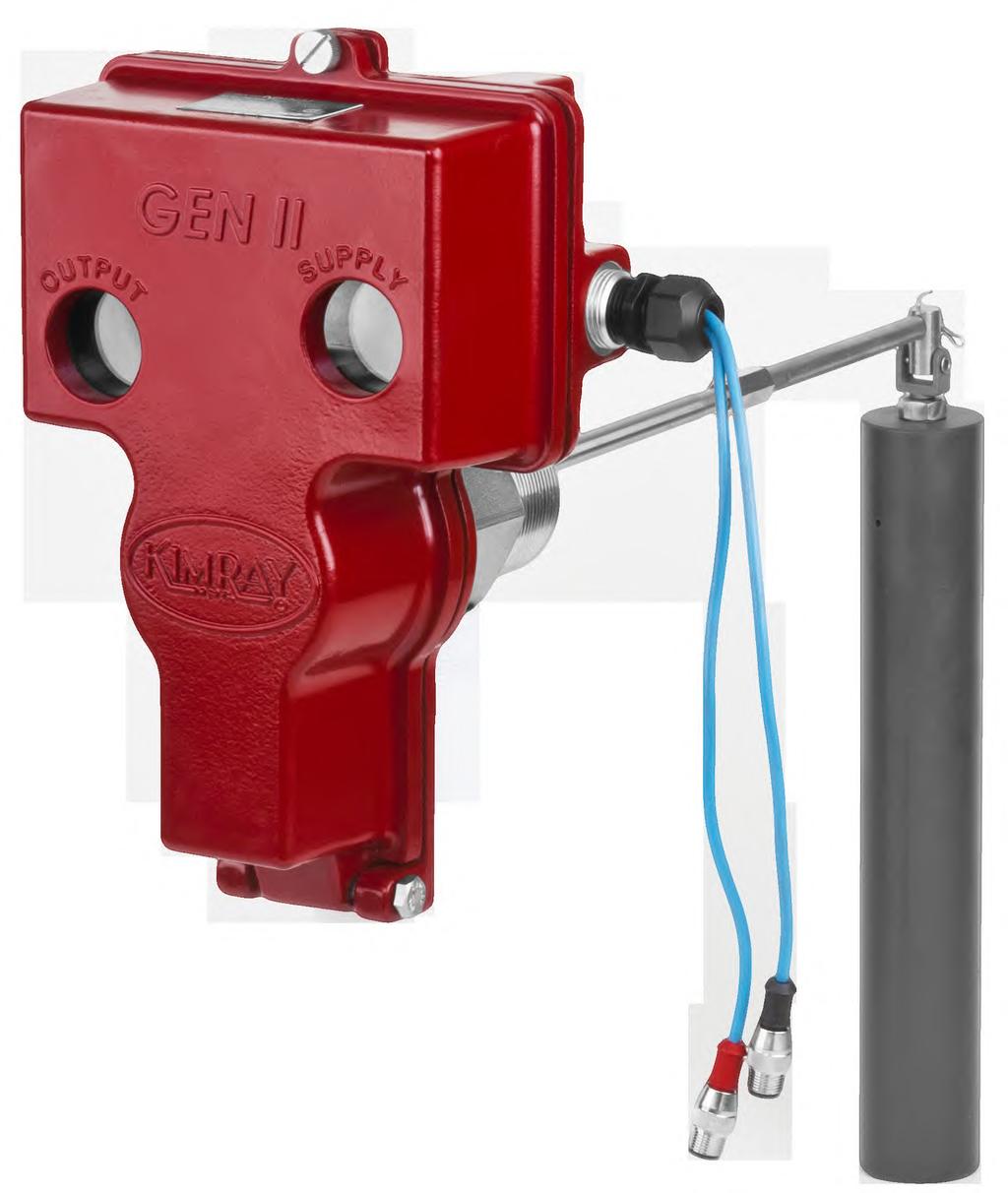
6 A7 ORIENTATION Item Description Qty 1 Rear Sensor (Black) 1 2 Front Sensor (Red) 1 3 Span Adjusting Knob 1 4 Tangent Arm 1 5 Spring Adjustment Knob 1 6 Waggle Arm 1 6 Kimray reserves the right to modify or improve the designs or specifications of such products at any time without notice.

7 1 Required Accessories The Electric Gen II requires the additional accessories of an isolation barrier and a set of sensor cables. The isolation barrier not only serves as the barrier between Class I Div 1 and Class II Div 1 areas, but also provides the necessary signal conditioning for the sensors to operate and translates them into easy to use relay outputs. The sensor cables are used to connect the isolation barrier (located in Class II Div 1 or less area) to the Electric Gen II (located in Class I Div 1 area). The cables available from Kimray are specifically pinned out to match the sensors and color coded for ease of use. These required accessories are available from Kimray in the following combinations. CMNL20 - Barrier with 20ft cables CMNL50 - Barrier with 50ft cables CMNL100 - Barrier with 100ft cables Alternatively, when ordering the Electric Gen II, the cables can be included with the level controller by adding the following suffixes: L50 - Barrier with 50ft cables L100 - Barrier with 100ft cables 2 Installation Before installing the Electric GEN II, inspect it for shipment damage and for foreign material that may have collected during shipment. Verify all pressure connections are tight before pressurizing the system. Be sure you fully understand the application, operation and connection of the device before installing. For threaded (NPT) process connections, use TFE tape or pipe thread sealant on external pipe threads. Verify that you have the required accessories listed above. 3 Wiring Instructions NOTE: Use good electrical wiring practices and consult with electrican. Power Requirements Ensure a stable DC power source is available for the application. A 1.5w (minimum) power supply is needed to power the required isolation barrier. Input voltage can be anywhere in the range from 10 to 30 VDC 1. Observe local wiring requirements for hazardous location usage. 2. Ensure power is off before connecting or removing wires 3. An isolation barrier is required for intrinsically safe installation and is needed for the Electric GEN II to function. 4. Sensor cables are required to connect the isolation barrier to the Electric GEN II 5. The barrier has six DIP switches on its face. All of these switches should be moved to the right. Terminal Descriptions Class I Div 2 (or less) side: Terminal 11: Vin (10-30 VDC) Terminal 12: GND (Return path for power) Terminals 7 & 10: Relay outputs for top level sensor Terminals 8 & 9: Relay outputs for span sensor Intrinsically Safe side (Class I Div 1) Terminal 4: To black (REAR) sensor (blue wire) Terminal 1: To black (REAR) sensor (brown wire) Terminal 5: To red (FRONT) sensor (blue wire) Terminal 2: To red (FRONT) sensor (brown wire) Tangent Arm position: The Electric Gen II utilizes common parts from the pneumatic Gen II. Unlike the pneumatic Gen II, the tangent arm is not to be adjusted and should ALWAYS be located in the front-most position. 7
8 4 Start-up and Test WARNING: Follow strict safety precautions when energizing and de-energizing any system. Permits may be required when commissioning or performing maintenance of electrical devices. Live circuits may generate a spark necessary to ignite flammable or combustible gas and vapors. 1. Apply power to the Electric GEN II barrier. 2. Pull down on the Spring adjustment knob to lift the displacer. LED 1 should light on the barrier to indicate an OPEN signal is being sensed and RELAY 1 outputs are now active. 3. Push up on the spring adjustment knob to lower the displacer. LED 2 should light on the barrier to indicate a CLOSE signal is being sensed and RELAY 2 outputs are now active. 5. Adjustments From the factory, the Electric Gen II is calibrated so that the rear sensor is triggered when water is detected at midpoint of the displacer. The front sensor triggers when the displacer lowers about 2 inches. This factory adjustment should satisfy most applications to detect level between gas, air and water. To compensate for varying specific gravities and for detecting liquid interface, it may be necessary to adjust the sensor trip points. The spring adjustment knob is used to change the upper trip point of the displacer. Loosening the spring adjustment knob will raise the upper trip point of the displacer. Tightening the spring adjustment knob will lower the upper trip point of the displacer. One turn of the spring adjustment knob will change the upper trip point by approximately one inch. The upper adjustment knob is used to change the lower trip point of the displacer. Lowering the front sensor will raise the lower trip point of the displacer. Raising the front sensor will lower the lower trip point of the displacer. One quarter turn (4-clicks) of the upper adjustment knob will change the lower trip point by approximately one inch. Front (red) Sensor Rear (black) Sensor Span Adjustment Knob NOTE: Outer most hole Liquid Level Adjustment 8
9 6 Wiring Diagrams Following are some example wiring diagrams for different applications 1. Liquid dump (Throttle or SNAP) using Electric Gen II level controller and Valvcon actuator: Throttle: With the ON/OFF control knob in 3-wire mode, the Electric Gen II barrier will send OPEN (CCW) and CLOSE (CW) to the Valvcon as needed causing it to partially open and remain somewhere between the upper trip point of the displacer and the lower trip point of the displacer. SNAP with non-adjustable span: With the ON/OFF control knob in 2-wire CCW mode, the Electric Gen II barrier will send an OPEN (CCW) signal when the liquid level reaches the upper trip point. As the liquid level falls below the upper trip point, the OPEN (CCW) signal will go away allowing the valve to close. This will result in a SNAP operation with a fixed span that is determined by hysteresis of the sensor, speed of the actuator, and flow rates of the liquid. The lower sensor is not used in this scenario. 9
10 2. Liquid dump (SNAP with fully adjustable span) In order to get SNAP operation with fully adjustable span, a relay is needed to latch in the OPEN (CCW) command until the CLOSE (CW) is triggered. 10
11 7 Installation of Intrinsically Safe Systems Installation of Intrinsically Safe Systems Drawing KE-IS1, Canadian Standards Association Certified Systems Kimray, Inc. 52 NW 42 nd St Oklahoma City, OK NON-HAZARDOUS LOCATION Any CSA Certified associated apparatus with Entity Concept parameters as follows: V OC 15V I SC 60mA C a C cable + 220nF L a L cable + 280µH HAZARDOUS (CLASSIFIED) LOCATION Class I, Div 1, Groups A,B,C,D; Class II, Div 1, Group G; Class III, Div 1 KIMRAY Electronic GenII Backmount with the following sensors: KIMRAY P/N 6805 KIMRAY P/N 6808 V max = 15V, I max = 60mA, C i = 220nF, L i = 280µH KIMRAY PN KIMRAY 6808 IS 2 5 KIMRAY 6805 Entity Parameters V oc (V) I sc (ma) C a (uf) AB/CE/DFG L a (mh) AB/CE/DFG /11.3/ /981/1H Each sensor 6805/6808 has the following entities: V max = 15V I max = 60mA C i = 220nF L i = 280µH Notes: 1. Control equipment connected to the associated apparatus must not use or generate more than 250Vrms or VOC. 2. Installation in the U.S. should be in accordance with ANSI/ISA RP12.6 Installation of Intrinsically Safe Systems for Hazardous (Classified) Locations and the Ntional Electrical Code (ANSI/NFPA 70) Sections 504 and Installations in Canada should be in accordance with the Canadian Electrical Code, CSA C22.1, Part 1, Appendix F. 4. Associated apparatus manufacturer s installation drawing must be followed when installing this equipment. 5. For U.S. installations, Kimray sensor part numbers 6808 and 6805 are approved for Class I, Zone 0 applications. 6. No revision to drawing without CSA-International approval. 7. Warning: Substitution of components may impair intrinsic safety. 8. If the electrical parameters of the cable are unknown, the following values may be used: Capacitance 60pF/foot; Inductance 0.2uH/foot. KE-IS1, Rev Date: 1/11/2012 Sheet 1 of 1 11

12 8 TROUBLESHOOTING Most troubleshooting can be done from the barrier by observing the LEDs and manipulating the Electric Gen II spring adjustment knob With normal operation: 1. All switches should be moved to the right. 2. The PWR LED must be lit. 3. With the spring adjustment knob pulled all the way down, LED 1 should be lit YELLOW and LED 2 will be OFF. 4. With the spring adjustment knob pushed all the way up, LED 1 should be OFF and LED2 will be lit YELLOW. There may be a location where both LEDs are lit yellow. This may or may not be a problem, it simply indicates there is some overlap in the sensor trigger locations. Opening up the span will remove this scenario. The PWR LED is off Problem Possible Cause(s) Possible Solution There may be a problem with the power supply. Use a voltmeter to check power from terminal 11 to terminal 12. Correct the input voltage. LED2 is RED The rear sensor cable may be shorted Turn the SC switch off. If the red light goes off, then there is a short in the wiring. Correct the wiring The rear sensor cable may be reversed. Verify that the brown wire of the sensor cable is connected to terminal 1 and the blue wire is connected to terminal 4. Correct the wiring The rear sensor cable may be open. Turn the WB switch off if red light turns off, then the sensor cable is open. Correct the wiring LED1 is RED The front sensor cable may be shorted. Turn the SC switch off. If the red light goes off, then there is a short in the wiring. Correct the wiring LED2 is always YELLOW The front sensor cable may be reversed The front sensor cable may be open. The front sensor has been lowered too far. Verify that the brown wire of the sensor cable is connected to terminal 2 and the blue wire is connected to terminal 5. Correct the wiring Turn the WB switch off if red light turns off, then the sensor cable is open. Correct the wiring Turn the upper adjustment knob to the left to raise the sensor. Operation appears to be reversed. The sensors may not be hooked up correctly. The sensors may not be configured correctly Verify that the rear sensor is tied to terminals 1 & 4 of the barrier and that the front sensor sensor is connected to terminals 2 & 5 of the barrier. Confirm the dip switches are all to the RIGHT (NC, WB, SC are selected). 12
13 NOTES 13
14 NOTES 14
15 Kimray is an ISO certified manufacturer. Kimray quality assurance process maintains strict controls of materials and the certification of parts used in the Kimray Electric Burner Valve. Please visit our website for up to date product data
16 Kimray.com 2018 Kimray, Inc. RM:0016 Issued 12/17
HIGH PRESSURE CONTROL VALVE R2L ACTUATOR
 R2L ACTUATOR All Rights Reserved. All contents of this publication including illustrations are believed to be reliable. And while efforts have been made to ensure their accuracy, they are not to be construed
METERING VALVE 2" STEM GUIDED
 2" STEM GUIDED All Rights Reserved. All contents of this publication including illustrations are believed to be reliable. And while efforts have been made to ensure their accuracy, they are not to be construed
LOW PRESSURE BALANCED VALVE DIAPHRAGM BALANCED
 DIAPHRAGM BALANCED All Rights Reserved. All contents of this publication including illustrations are believed to be reliable. And while efforts have been made to ensure their accuracy, they are not to
HIGH PRESSURE CONTROL VALVE PISTON BALANCED
 PISTON BALANCED All Rights Reserved. All contents of this publication including illustrations are believed to be reliable. And while efforts have been made to ensure their accuracy, they are not to be
Kimray reserves the right to modify or improve the designs or specifications of such products at any time without prior notice Kimray Inc.
 TREATER VALVE All Rights Reserved. All contents of this publication including illustrations are believed to be reliable. And while efforts have been made to ensure their accuracy, they are not to be construed
PRESSURE REGULATOR BACK PRESSURE TO ATMOSPHERE WITH OUTSIDE SUPPLY
 PRESSURE REGULATOR BACK PRESSURE TO ATMOSPHERE WITH OUTSIDE SUPPLY All Rights Reserved. All contents of this publication including illustrations are believed to be reliable. And while efforts have been
LIMIT SWITCH Hawkeye - HX Magnetic Solid State Proximity Sensors Installation, Maintenance and Operating Instructions (HX )
") LIMIT SWITCH Hawkeye - HX Magnetic Solid State Proximity Sensors Installation, Maintenance and Operating Instructions (HX ) Publication# 03revA Table of Contents Publication# 03revA Table Of Contents...
LIMIT SWITCH Hawkeye - HX Magnetic Solid State Proximity Sensors Installation, Maintenance and Operating Instructions (HX ) Publication# 03revA Table of Contents Publication# 03revA Table Of Contents...
FAIRCHILD T8001 SERIES STANDARD RANGE MINIATURE TWO-WIRE, P/I PRESSURE TRANSDUCER. Installation, Operation and Maintenance Instructions
 FAIRCHILD T800 SERIES STANDARD RANGE MINIATURE TWO-WIRE, PI PRESSURE TRANSDUCER Installation, Operation and Maintenance Instructions Model TT800 Model TA800 Model TD800 Inlet Port (Channel 2) Inlet Port
WARNING! READ BEFORE INSTALLATION
 A4 INTRINSICALLY SAFE & NON-INCENDIVE RATED PRESSURE TRANSMITTER INSTRUCTION SHEET WARNING! READ BEFORE INSTALLATION 1. GENERAL: A failure resulting in injury or damage may be caused by excessive overpressure,
m WARNING! READ m BEFORE INSTALLATION
 m WARNING! READ m BEFORE INSTALLATION 1. GENERAL: A failure resulting in injury or damage may be caused by excessive overpressure, excessive vibration or pressure pulsation, excessive instrument temperature,
Installation, Operation and Maintenance Instructions Output Range Part Number Input psi bar Impedance Output Range
 Type 500X Electropneumatic Transducer (I/P, E/P) Installation, Operation and Maintenance Instructions Ordering Information Type 500X I/P Transducers Output Range Part Number Input psi bar Impedance Pilot
A5000GEC-24VDC ZERO SPEED SWITCH
 A208-05, Page 1 952-361-3026, INC. (Fax) 952-368-4129 327 LAKE HAZELTINE DRIVE, CHASKA, MN 55318 800-328-0738 A5000GEC-24VDC ZERO SPEED SWITCH Introduction The MAXIGARD A5000GEC-24VDC is a zero speed switch
Certificate of Compliance
 Certificate of Compliance Certificate: 70054084 Issued to: Emerson - Rosemount, Micro Motion Inc. 12001 Technology Dr. Eden Prairie, Minnesota 55344 USA Attention: Paul Schilke The products listed below
A1500, A1500NF SPEED SWITCH SINGLE SET POINT - SELF CONTAINED. Introduction
 A186-05, Page 1 952-361-3026, INC. (Fax) 952-368-4129 327 LAKE HAZELTINE DRIVE, CHASKA, MN 55318 800-328-0738 A1500, A1500NF SPEED SWITCH SINGLE SET POINT - SELF CONTAINED Introduction The MAXIGARD A1500
Fisher i2p 100 Electro Pneumatic Transducer
 Product Bulletin D103197X012 i2p 100 Transducer Fisher i2p 100 Electro Pneumatic Transducer The Fisher i2p 100 electro pneumatic transducer, shown in figure 1, uses a converter module that converts a milliampere
Fisher SS-263 Volume Booster
 Instruction Manual SS-263 Volume Booster Fisher SS-263 Volume Booster Contents Figure 1. Fisher SS-263 Volume Booster Introduction... 1 Scope of Manual... 1 Description... 1 Educational Services... 2 Specifications...
ME217PIB / ME503PIB SMART INTERLOCK TECHNOLOGY ACME ADAPTER INTERLOCK BRACKET INSTALLATION AND OPERATING INSTRUCTIONS
 ME217PIB / ME503PIB SMART INTERLOCK TECHNOLOGY ACME ADAPTER INTERLOCK BRACKET INSTALLATION AND OPERATING INSTRUCTIONS ME825-16 / ME825-10 (Not Included) ME217PIB / ME503PIB ME229F5-1 / ME449F8-1 (Not Included)
Certificate of Compliance
 FF0001 Certificate of Compliance Certificate: 1345550 Issued to: Eaton Electric Ltd. Great Marlings Butterfield, Luton Bedfordshire LU2 8DL United Kingdom Attention: Mr. Peter Rigling The products listed
Type 2000 Transducer Product Instructions
 Type 2000 Transducer Product Instructions The Type 2000 is an electro-pneumatic device that regulates an unregulated supply pressure down to an electronically-controlled output pressure. There are two
EG Series Installation Manual
 EG Series Installation Manual Convenient Micro Connectors (M) speed installation and maintenance Enclosure is fully potted and sealed to eliminate threat of moisture contamination in the wiring and electronics
FAIRCHILD T5200 SERIES ELECTRO-PNEUMATIC TRANSDUCER Installation, Operation and Maintenance Instructions
 FAIRCHILD T500 SERIES ELECTRO-PNEUMATIC TRADUCER Installation, Operation and Maintenance Instructions Identification Number Underwriting Group Factory Mutual Canadian Standard T (F) (C) 500- Approval Class
Solenoid Valves Type 3963
 Mounting and Operating Instructions Solenoid Valves Type 3963 Fig. 1 General Assembly, commissioning and operation of these devices may only be performed by experienced personnel. Proper shipping and appropriate
Integrated Control modules
 .60.0 Rev. 0 Page of 9 Integrated Control modules QC, QC2 and QC Features: - Basic actuator functions for: - Spring return applications, or - Double acting applications or, - Double acting Fail in Last
Fisher VBL Volume Booster
 Instruction Manual VBL Volume Booster Fisher VBL Volume Booster Contents Introduction... 1 Scope of Manual... 1 Description... 1 Specifications... 2 Educational Services... 2 Installation... 4 Mounting...
CP-9301 CP Application. Features. Applicable Literature. Electronic Actuator Drives General Instructions
 CP-90 CP-90 Electronic Drives General Instructions Application The CP-90 and CP-90 electronic actuator drives process a variable input signal from a controller to provide proportional control of an electric
Carbon Monoxide Transmitter
 Introduction The CO Transmitter uses an electrochemical sensor to monitor the CO level and outputs a 4-20 ma signal. The standard product features a 2- wire loop-powered output. Optionally, the device
CIVACON GROUND VERIFICATION RACK MONITOR SYSTEM and ASSOCIATED EQUIPMENT
 GROUND VERIFICATION RACK MONITOR SYSTEM and ASSOCIATED EQUIPMENT INSTALLATION AND WIRING INSTRUCTIONS MANUAL 8030 MANUAL PART NUMBER JANUARY 2011. 4304 MATTOX RD. KANSAS CITY, MO 64150 TABLE OF CONTENTS
Induction Power Supplies
 Induction Power Supplies 7.5kW; 135 400kHz 480V version (Integral Heat Station) User s Guide Model 7.5-135/400-3-480 SMD Control Brds Rev. D 5/08 Table of Contents 1. Specifications and features...3 2.
Fisher 2052 Diaphragm Rotary Actuator
 Instruction Manual 2052 Actuator Fisher 2052 Diaphragm Rotary Actuator Contents Introduction... 1 Scope of Manual... 1 Description... 1 Specifications... 4 Installation... 4 Actuator Mounting and Changing
Fisher L2e Electric Level Controller
 Instruction Manual L2e Controller Fisher L2e Electric Level Controller Contents Introduction... 1 Scope of Manual... 1 Description... 2 Specifications... 2 Educational Services... 2 Installation... 4 Attaching
TECHNICAL BULLETIN. Logix 510si Series Digital Positioner. Experience In Motion FCD LGENTB /09
 Logix 510si Series Digital Positioner TECHNICAL BULLETIN FCD LGENTB0510-01 09/09 Experience In Motion Introduction The Logix 510si series are single acting, user-friendly digital positioners. As all positioners
The T5220 Series Electro-Pneumatic Transducer converts a DC current or voltage input signal to a directly proportional pneumatic output.
 GENERAL INFORMATION T5220 SERIES TRANSDUCER Electro-Pneumatic (I/P, E/P) APPLICATIONS The T5220 Series Electro-Pneumatic Transducer converts a DC current or voltage input signal to a directly proportional
Reproduction or other use of this Manual, without the express written consent of Vulcan, is prohibited.
 SERVICE MANUAL ELECTRIC BRAISING PANS (30 & 40 GALLON) VE30 VE40 ML-126849 ML-126850 VE40 SHOWN - NOTICE - This Manual is prepared for the use of trained Vulcan Service Technicians and should not be used
Model DF233 Control Valve
 Figure 1 DF233 Control Valve TABLE OF CONTENTS Introduction 2 Body and Packing Reassembly 7 Specifications 3 Fail Closed Actuator Reassembly 8 Valve Sizes 3 Fail Open Actuator Reassembly 9 Unpacking 4
ACCUTRAK ROTARY MODELS 1040/9358/2004/9044/9468/5004/5044/2007/9479/5050 INSTALLATION AND OPERATIONS MANUAL
 Installation and operating instructions for AccuTrak position monitor rotary models 1 INTRODUCTION 1.1 Product Certification 1040/9358: CSA Type 4 (Cert. #1185829) 2004: CSA Type 4 (Cert. #2599677) 9044:
P200 P/I Transducer. Installation, Operation, and Maintenance Instructions INTRODUCTION
 INTRODUCTION Scope This manual provides instructions for the installation, adjustment, maintenance, and parts ordering of the P200 Pneumatic-to-Current P/I Transducer. Due to its over-engineered design,
I/P CONVERTER INSTRUCTION MANUAL (E)IM-TE100/00-R5
IM-TE100/00-R5") TE100 100,200 I/P CONVERTER INSTRUCTION MANUAL (E)IM-TE100/00-R5 Safety Precautions Always read these instructions before using the I/P converter.! WARNING:Indicates instructions that, if not followed
TE100 100,200 I/P CONVERTER INSTRUCTION MANUAL (E)IM-TE100/00-R5 Safety Precautions Always read these instructions before using the I/P converter.! WARNING:Indicates instructions that, if not followed
Product Specification A1000i Loop Powered/4-20mA Submersible Level Transmitter/Transducer
 CONTROL SYSTEMS 1239 WILLOW LAKE BOULEVARD VADNAIS HEIGHTS, MINNESOTA 55110 651 766 2700 Fax: 651 766 2701 www.control systems.usfilter.com Product Specification A1000i Loop Powered/4-20mA Submersible
Model DF269 Control Valve
 Figure 1 DF269 Control Valve TABLE OF CONTENTS Introduction 2 Fail Open Actuator Disassembly 6 General 2 Body and Packing Reassembly 7 Scope 2 Fail Closed Actuator Resassembly 8 Specifications 3 Fail Open
Baumann Sanitary Diaphragm Angle and Inline Control Valve
 Instruction Manual 84000 Valve Baumann 84000 Sanitary Diaphragm Angle and Inline Control Valve Contents Introduction... 1 Scope of Manual... 1 Safety Precautions... 2 Maintenance... 2 Flow Direction...
Connectors for Diagnostic Testing with the FlowScanner Valve Diagnostic System
 Instruction Manual Connectors for FlowScanner System Connectors for Diagnostic Testing with the FlowScanner Valve Diagnostic System Contents Introduction............................... 1 Scope of Manual.........................
MAXIGARD A2000 SPEED SWITCH. Introduction
 A107-05, Page 1 952-361-3026, INC. (Fax) 952-368-4129 327 LAKE HAZELTINE DRIVE, CHASKA, MN 55318 800-328-0738 MAXIGARD A2000 SPEED SWITCH Introduction The Maxigard A2000 Speed Switch is designed to monitor
LEVEL SWITCH INTRODUCTION APPLICATIONS
 LEVEL SWITCH LEVEL SWITCH INTRODUCTION Kimray pneumatic and electric switches give customers dependable service in all types of environments. Both can be used for high or low level control, and the 316
Electro-Pneumatic Positioner Series 830/831-WP/EX. Operation & Maintenance Manual
 Electro-Pneumatic Positioner Series 830/831-WP/EX Operation & Maintenance Manual Electro-Pneumatic Positioner Model 830/831- WP/EXP This operation & maintenance manual corresponds to Forbes Marshall Arca
Certificate of Compliance
 Certificate of Compliance Certificate: 1132623 (LR 82598) Master Contract: 160686 Project: 2567317 Date Issued: November 5, 2012 Issued to: Endress + Hauser Flowtec AG Kagenstrasse 7 Reinach, Basel Land
Fisher 546 Electro Pneumatic Transducer
 546 Transducer Product Bulletin Fisher 546 Electro Pneumatic Transducer Fisher 546 transducers receive a direct current input signal and use a torque motor, nozzle flapper, and pneumatic relay to convert
8460SRC Replacement Chassis for Scully ST-6 and Biclops Monitors
 8460SRC Replacement Chassis for Manual Part Number: OPTI-THERM is a registered trademark of CIVACON, A Dover Company QUICK-START is a registered trademark of CIVACON, A Dover Company Biclops is a registered
Bettis M11 Manual Hydraulic Override System Operating Instructions for HD, T, and G Series Pneumatic and Hydraulic Actuators
 Instruction Manual D102755X012 March 2010 Bettis M11 Bettis M11 Manual Hydraulic Override System Operating Instructions for HD, T, and G Series Pneumatic and Hydraulic Actuators The following instruction
Surepowr Series 100 Installation Manual
 Surepowr Series 100 Installation Manual Safety First In the maintenance and operation of mechanical equipment, safety is the basic factor which must be considered at all times. Through the use of the proper
K10 Intrinsically Safe Electro-Pneumatic Positioner Operating Manual
 K0 Intrinsically Safe Electro-Pneumatic Positioner Operating Manual Pneumatic Connection Outlet Port Gauge Single Acting Actuator (Spring Return): For single acting actuators Outlet Port 2 is to be plugged.
CM3000 SIGNAL TRANSMITTER. Introduction. The MAXIGARD CM3000 is designed to convert shaft speed into a 4/20 ma or 0-10 VDC analog output signal.
 CM228-03, Page 1 952-935-4201, INC. (Fax) 952-935-9628 3947 MEADOWBROOK ROAD, MINNEAPOLIS, MN 55426 800-328-0738 CM3000 SIGNAL TRANSMITTER Introduction The MAXIGARD CM3000 is designed to convert shaft
Product Specification A1000i Loop Powered/4-20mA Submersible Level Transmitter/Transducer
 CONTROL SYSTEMS 1239 WILLOW LAKE BOULEVARD VADNAIS HEIGHTS, MINNESOTA 55110 651 766 2700 Fax: 651 766 2701 www.control systems.usfilter.com Product Specification A1000i Loop Powered/4-20mA Submersible
Rated for use on 110/120VAC 60Hz and 220/240VAC 60Hz applications
 WPC-1 Rated for use on 110/120VAC 60Hz and 220/240VAC 60Hz applications Installation Instructions: Read these instructions in their entirety before performing any installation work. FOR USE WITH POOL AND
CEMLINE CORPORATION P. O. BOX 55 CHESWICK, PENNSYLVANIA Phone: (724) FAX (724)
 FAX (724)") Installation, Operation, and Maintenance Manual CEMLINE CORPORATION Electronic Controls for Water Heaters with RWD45U Controller CEMLINE CORPORATION P. O. BOX 55 CHESWICK, PENNSYLVANIA 15024 Phone: (724)
Installation, Operation, and Maintenance Manual CEMLINE CORPORATION Electronic Controls for Water Heaters with RWD45U Controller CEMLINE CORPORATION P. O. BOX 55 CHESWICK, PENNSYLVANIA 15024 Phone: (724)
EXT HEPA/CARBON FUME HOOD
 EXT HEPA/CARBON FUME HOOD POLYPROPYLENE Installation and Operations Manual EXT HEPA/CARBON FUME HOOD Installation and Operations Manual Revision: 28-Jun-18 Page 2 of 12 EXT HEPA/CARBON FUME HOOD Installation
CVS 7970 High-Low Pressure Pilot
 Instruction Manual CVS 7970 High-Low Pressure Pilot Introduction This instruction manual includes the following information for CVS 7970 High-Low Pressure Pilot: 1. Description 2. Piston Arrangement Changeover
INSTALLATION, OPERATION, AND MAINTENANCE MANUAL WELKER TIMER/CONTROLLER
 INSTALLATION, OPERATION, AND MAINTENANCE MANUAL WELKER TIMER/CONTROLLER MODEL 6Tc DRAWING NUMBERS AD717BO EL530 MANUAL NUMBER IOM-002 REVISION Rev. E, 08/11/2015 TABLE OF CONTENTS SAFETY 3 1. PRODUCT INFORMATION
Nuheat WEATHER-READY HEAT TRACE PIPE FREEZE PROTECTION SYSTEM. Self-Regulating Heating Cable Installation Guide. UV Resistant Polyolefin Outer Jacket
 Nuheat WEATHER-READY HEAT TRACE PIPE FREEZE PROTECTION SYSTEM Self-Regulating Heating Cable Installation Guide Tinned Copper Braid UV Resistant Polyolefin Outer Jacket 16 AWG Bus Wire Polyolefin Inner
M Series Manual Handwheel Gear Actuator
 Instruction Manual M Series Actuator M Series Manual Handwheel Gear Actuator Contents Introduction............................... 1 Scope of Manual......................... 1 Description..............................
Baumann Mikroseal Control Valve
 Instruction Manual 81000 Valve Baumann 81000 Mikroseal Control Valve Contents Introduction... 1 Scope of Manual... 1 Safety Precautions... 2 Maintenance... 3 Installation... 3 Air Piping... 4 Flow Direction...
Controlled Ferroresonant Ballast (CFB) Generation #3. Manual
 Generation #3. Manual") Controlled Ferroresonant Ballast (CFB) Generation #3 Manual SHAPE LLC 2105 Corporate Dr. Addison, IL 60101 (630) 620-8394 Toll Free (800) 367-5811 FAX (630) 620-0784 CONTENTS GENERAL DESCRIPTION... 3 INSTALLATION...
Controlled Ferroresonant Ballast (CFB) Generation #3 Manual SHAPE LLC 2105 Corporate Dr. Addison, IL 60101 (630) 620-8394 Toll Free (800) 367-5811 FAX (630) 620-0784 CONTENTS GENERAL DESCRIPTION... 3 INSTALLATION...
Lube Level Maintainer
 Lube Level Maintainer Model LM500-TF-ATEX Installation Instructions 00-02-0745 2013-09-16 Section 15 Ex ic IIC T5 Gc X -20 o C < Ta < 85 o C NOTE: To use in an ATEX environment the metal vent cap must
4 Redundant Control System
 4 Redundant Control System Introducing the all NEW RCS Configurator Safety Instrumented Systems Process Reliability Process Valve Diagnostics COMPLETE FUNCTIONAL SAFETY WITH ENHANCED RELIABILITY The Redundant
TECHNICAL SERVICE DEPARTMENT Technical Service Bulletin LowNOx Commercial Gas Electronic Spark Ignition Sequence
 The Universal TM gas LowNOx series water heaters contain an electronic spark ignition system. The heater is connected to a 120VAC power source required by the transformer. The transformer steps down the
The Combustex Pilot Pro 500 Ignition System with Pilot Tip and Flame Sensor
 OPERATIONS MANUAL The Combustex Pilot Pro 500 Ignition System with Pilot Tip and Flame Sensor The CSA approved alternative ignition system delivering safety, reliability and versatility. KEY FEATURES Unique
INLINE Flow sensor for hazardous area II 1 G/D - II 2 D - II 3 GD - I M1
 INLINE Flow sensor for hazardous area II G/D - II D - II GD - I M Type SE0 Ex can be combined with... Flow meter with NAMUR or NPN/PNP output signal Mounting, dismounting of electronics by a Quarter-Turn
DuraDrive MF /MS Series Non-spring Return Rotary Electronic Damper Actuators 24 Vac Three-position/Modulating
 General Instructions DuraDrive MF4-653/MS4-653 Series Non-spring Return Rotary Electronic Damper Actuators 4 Vac Three-position/Modulating Description The DuraDrive direct-coupled, 4 Vac, non-spring return
M Series Manual Handwheel Gear Actuator
 Instruction Manual D500237X0 M Series Actuator M Series Manual Handwheel Gear Actuator Contents Introduction... 1 Scope of Manual... 1 Description... 1 Specifications... 1 Installation... 3 Operation...
Certificate of Compliance
 Certificate of Compliance Certificate: 1345550 (LR 36637) Master Contract: 152423 Issued to: Measurement Technology Limited Great Marlings Butterfield Luton, Bedfordshire LU2 8DL United Kingdom Attention:
PHOTOVOLTAIC SYSTEM CONTROLLERS SUNSAVER MODELS INCLUDED IN THIS MANUAL SS-6 / SS-6L SS-10 / SS-10L SS-10-24V / SS-10L-24V SS-20L SS-20L-24V
 PHOTOVOLTAIC SYSTEM CONTROLLERS OPERATOR S MANUAL SUNSAVER MODELS INCLUDED IN THIS MANUAL SS-6 / SS-6L SS-10 / SS-10L SS-10-24V / SS-10L-24V SS-20L SS-20L-24V 6A / 12V 10A / 12V 10A / 24V 20A / 12V 20A
OPERATING INSTRUCTIONS PLEASE READ CAREFULLY
 OPERATING INSTRUCTIONS PLEASE READ CAREFULLY 925-0330 Rev 0 0416 TABLE OF CONTENTS SAFETY SUMMARY... 3 SPECIFICATIONS... 4 1.0 INTRODUCTION/DESCRIPTION.... 5 2.0 LOCATION AND MOUNTING... 5 3.0 CONNECTIONS
Precision Pulse Volumetric Fluid Flow Meter
 INSTRUCTIONS PARTS LIST 308 314 This manual contains important warnings and information. READ AND RETAIN FOR REFERENCE Rev. A Precision Pulse Volumetric Fluid Flow Meter Models PPM 3050, 3100, and 3550
BULLETIN NO.ELEC IM121/10A Replaces IM121/09A
 Mid-West Instrument BULLETIN NO.ELEC IM121/10A Replaces IM121/09A INSPECTION Model 121 Indicating Differential Pressure Switch / Transmitter Electrical: Installation and Operating Instructions Upon receipt
HIGH POWER SOLENOID DRIVER 1
 Elactis SA Switzerland Phone : Fax : E-mail : Web : +41 22 364 65 85 +41 22 364 65 87 info@elactis.com http://www.elactis.com HIGH POWER SOLENOID DRIVER 1 ADRV1012K 1 This datasheet is a preliminary description.
Baumann Little Scotty Bronze Control Valve
 Instruction Manual 24000 Valve Baumann 24000 Little Scotty Bronze Control Valve Contents Introduction... 1 Scope of Manual... 1 Safety Precautions... 2 Maintenance... 2 Installation... 3 Air Piping...
Model 5000 Level Controller
 Features Multiple Configurations The 5000 level controller is easily configured for either reverse or direct actions for both pneumatic and electric pilot options. The pneumatic pilot is available in snap
EI, EIO INTRINSICALLY SAFE VALVES
 213 Definitions C a : Maximum Allowed Capacitance I sc : Maximum Output Current V oc : Maximum Output Voltage C i : Maximum Internal Capacitance L a : Maximum Allowed Inductance V max : Maximum Input Voltage
Fisher 1052 Size 20 Diaphragm Rotary Actuator with F and G Mounting Adaptation
 Instruction Manual 1052 Size 20 Actuator (F & G) Fisher 1052 Size 20 Diaphragm Rotary Actuator with F and G Mounting Adaptation Contents Introduction... 1 Scope of manual... 1 Description... 1 Specifications...
Fisher 2506 and 2516 Receiver/Controllers
 Instruction Manual Fisher 2506 and 2516 Receiver/Controllers Contents Introduction... 2 Scope of Manual... 2 Description... 2 Specifications... 2 Educational Services... 4 Installation... 5 Mounting the
Quarter Master Series 94 Actuator
 Quarter Master Series 94 Actuator Installation, Operation and Maintenance Manual Assembly Series 94 Manual Rev V 9/5/13 Page 1 of 12 Table of Contents Series 94 Electric Actuator Introduction... 3 Description...
SPECIFICATIONS ATTENTION OPERATION DESCRIPTION
 EMP-5 Installation Manual - P/N 80103 - Ed. 01/09 EMP-5 Current or Voltage Input Drive Modulating Actuator Installation Instructions 1 7 SPECIFICATIONS The EMP-5 series actuators provide damper control
The Combustex Pilot Pro 900 Ignition System with Pilot Tip and Flame Sensor
 OPERATIONS MANUAL The Combustex Pilot Pro 900 Ignition System with Pilot Tip and Flame Sensor KEY FEATURES Strong, Reliable Ignition & Pilot Flame Rapid Flame Response LED Flame Status Indicator Fully
MF /MS Series
 MF41-6153/MS41-6153 Series 24 Vac, Three-position/Modulating Non-spring Return Rotary Electronic Damper SmartX Actuators General Instructions Description The direct-coupled, 24 Vac, non-spring return electronic
CAP ANALOG 4100 INSTALLATION & OPERATION MANAUL
 CAP ANALOG 4100 INSTALLATION & OPERATION MANAUL An L&J Technologies Co. 5911 Butterfield Road Hillside, IL 60162 Phone: 708-236-6000 Fax: 708-236-6006 1 was started in 1976 by a young engineer who had
Phenix Technologies Inc. 75 Speicher Drive Accident, Maryland 21520
 USER S MANUAL PORTABLE HIGH CURRENT TEST SET MODEL NUMBER HC2 Version 4.0 Phenix Technologies Inc. 75 Speicher Drive Accident, Maryland 21520 Copyright Phenix Technologies, Inc. Rev 11/20/2014 nab TABLE
AGELKOM CAP04 Plasma and Oxy Fuel Torch height control for sheet metal cutting machines Height Sensor & Controller
 6 PIN INTERFACE BNC HEIGHT CONTROL KNOB CAP 04 CAPACITIVE HEIGHT CONTROLLER DOWN IN POSITION UP TOUCH CABLE FAULT AGELKOM CAP04 Plasma and Oxy Fuel Torch height control for sheet metal cutting machines
LIMIT SWITCH Axiom - AX
 LIMIT SWITCH Axiom - AX with SST Switching Sensors Installation, Maintenance and Operating Instructions (AX33 ) Publication# 10532revB 2 Table of Contents Publication# 10532revB Table Of Contents... Page
Zero Point Calibration HART Communicating Fisher FIELDVUE DVC6200 Digital Valve Controllers
 Zero Point Calibration HART Communicating Fisher FIELDVUE s The Zero Point Calibration procedure allows you replace an existing DVC6200 digital valve controller without performing a travel calibration.
Your Global Flow Control Partner. Series 70 24V On/Off Electric Actuator Operation and Maintenance Manual
 Your Global Flow Control Partner Series 70 Table of Contents 1. Definition of Terms.......................................2 2. Safety............................................. 2 3. Storage............................................2
Valve model number description
 0-30.3-6 Valve model number description Every MAXON Series 8000 Valve can be accurately identified by the model number shown on the valve nameplate. The example below shows a typical Series 8000 Valve
TMS Series MP46x Flex Probes* Installation Instructions
 PNEUMERCATOR Liquid Level Control Systems TMS Series MP46x Flex Probes* Installation Instructions Model MP461, MP462 And MP463 Magnetostrictive Flex Probes Installation For: MODEL TMS2000 and MODEL TMS3000
Type 500X. Electropneumatic Transducer (I/P, E/P) Installation, Operation and Maintenance Instructions. Ordering Information.
 Installation, Operation and Maintenance Instructions. Ordering Information.") Type 500X Electropneumatic Transducer (I/P, E/P) Installation, Operation and Maintenance Instructions Ordering Information Type 500X I/P Transducers Output Range Part Number Input psi kpa Impedance 500-AA
Type 500X Electropneumatic Transducer (I/P, E/P) Installation, Operation and Maintenance Instructions Ordering Information Type 500X I/P Transducers Output Range Part Number Input psi kpa Impedance 500-AA
C3000 SIGNAL TRANSMITTER. Introduction
 C131-05, Page 1 952-361-3026, INC. (Fax) 952-368-4129 327 LAKE HAZELTINE DRIVE, CHASKA, MN 55318 800-328-0738 C3000 SIGNAL TRANSMITTER Introduction The MAXIGARD C3000 series is designed to convert shaft
Electropneumatic Converters i/p Converters Type 6111 Mounting and Operating Instructions EB 6111 EN
 Electropneumatic Converters i/p Converters Type 6111 Fig. 1 Type 6111 in standard version Fig. Type 6111 mounted on a supply air manifold Fig. 3 Type 6111 in field enclosure Mounting and Operating Instructions
SUREPOWR TM SERIES -SURE 24/25 FIELD INSTALLATION INSTRUCTIONS
 SUREPOWR TM SERIES -SURE 4/5 FIELD INSTALLATION INSTRUCTIONS Safety First In the maintenance and operation of mechanical equipment, SAFETY is the basic factor which must be considered at all times. Through
Installation and Maintenance Instructions. World Leader in Modular Torque Limiters. PTM-4 Load Monitor
 World Leader in Modular Torque Limiters Installation and Maintenance Instructions PTM-4 Load Monitor 1304 Twin Oaks Street Wichita Falls, Texas 76302 (940) 723-7800 Fax: (940) 723-7888 E-mail: sales@brunelcorp.com
Fisher 657 Diaphragm Actuator Sizes and 87
 Instruction Manual 657 Actuator (30-70 and 87) Fisher 657 Diaphragm Actuator Sizes 30 70 and 87 Contents Introduction... 1 Scope of Manual... 1 Description... 2 Specifications... 2 Installation... 3 Mounting
Fisher 3660 and 3661 Positioners
 3660 and 3661 Positioners Product Bulletin Fisher 3660 and 3661 Positioners Fisher 3660 pneumatic and 3661 electro pneumatic single acting positioners are used with various actuators on sliding stem valves
Type Installation, Operation and Maintenance Instructions. Ordering Information. Contents CA20 -
 Type 2000 Pneumatic and Electropneumatic Valve Positioner Installation, Operation and Maintenance Instructions Ordering Information Use this coding system to order Model CA20 - Type of Positioner 00 P/P
EXT DUCTLESS FUME HOOD
 EXT DUCTLESS FUME HOOD POLYPROPYLENE Installation and Operations Manual EXT DUCTLESS FUME HOOD Installation and Operations Manual Revision: 1-Feb-16 Page 2 of 12 EXT DUCTLESS FUME HOOD Installation and