Please contact BrakeAway Products tech support for additional (503) or
|
|
|
- Britton Maxwell
- 5 years ago
- Views:
Transcription

1 Congratulations on the purchase of your new BrakeAway Motorcycle Cruise Control. At BrakeAway Products, we are committed to your complete satisfaction. With proper installation, use, and periodic maintenance, this cruise control is built for the long haul in more ways than one. Please follow all of the instructions carefully to insure your riding safety and enjoyment. Proper use after installation: (The following information is to be shared with any person who will be riding or buying any Motorcycle equipped with a BrakeAway Cruise Control). Always include your cruise control in your standard pre-ride inspection. Make sure the unit engages easily, the throttle should turn with little effort but remain in position on its own. The unit should effortlessly snap to the disengaged position with a slight pull of the brake lever or tap of the Manual Release Lever. The throttle should always turn freely when the unit is disengaged. Check the cam (see diagram on last page) for wear at the point of contact with the brake lever or damage of any kind. All fasteners must be tight. Warning! Never use this product with worn or damaged parts. All replacement parts are obtainable by contacting BrakeAway Products Inc at (503) or customersevice@brakeawayproducts.com Once you re on the open road and ready to cruise, reach the speed you want to maintain and let your R.P.M.s level off. While holding the throttle still, reach with your right thumb only and push the engage button until it snaps. Your bike should now maintain your set speed on its own. You can make adjustments for up or downhill grades with a slight twist of the throttle while engaged. To disengage the unit simply pull the front brake or push forward on the manual release lever with your right thumb until the unit snaps to the disengaged position. Always keep your cruise control clean and free of debris, occasionally lubricate the catch pin with a light grease or chain wax. Never forget that you maintain control even when unit is engaged. Always be aware of your cruising speed and maintain safe distance from objects or vehicles in front of you. Never let go of your throttle. The BrakeAway cruise control is not intended for hands free or one handed riding, this unit was specifically designed to allow the rider to safely rest a cramping throttle hand on the throttle. BrakeAway Products wishes you many years of cramp free cruising, ENJOY!!! All components are obtainable from BrakeAway Products Inc. (503) or customerservice@brakeawayproducts.com Please contact BrakeAway Products tech support for additional (503) or techsupport@brakeawayproducts.com


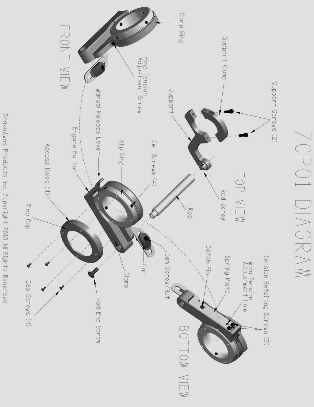
2 7CP01 BrakeAway Motorcycle Cruise Control Installation Instructions Before you begin, If your bike is not fuel injected, turn the fuel supply OFF to avoid flooding. Check the action of your return spring by turning your throttle and quickly releasing it. This action should not be effected by proper installation of this device. Correct any excessive play in the brake lever. For the brake release mechanism to function properly, your brake lever must not move more than ¼ up and down at the outside end. Detach Diagram on last page and place it in a visible location for quick part name reference and identification. Section 1: Support installation 1.A: Loosen the two screws in the clamp that holds your brake lever/master cylinder in place on your handlebar. Temporarily slide your brake lever/master cylinder assembly away from the switch housing to create a gap for the support. 1.B: Remove the two 4-40 screws in the support clamp to separate it from the support. Loosen the remaining rod screw in the support to make sure it is not clamping the rod hole closed. 1.C: Work the support to the shown position under the handlebar into the gap next to the switch housing. Re-attach the support clamp over the top of the handlebar using the two 4-40 screws. Snug the screws just enough so you can rotate the unit and have it stay in position. You will need to rotate the support later in the installation. Ref. 1.A Ref. 1.B Ref. 1.C Loosen brake lever clamp. Move Remove support clamp and Support in position under handleit over to create space for support. loosen rod screw. bar. Replace clamp, snug screws. 1.D Move the brake lever/master cylinder back over next to the support but make sure it is not touching it. Re-tighten the clamp screws so the brake lever is secure in a comfortable position. If any part of the brake lever/master cylinder assembly is touching the support, it can bend or bind the support as you tighten the clamp screws. This will cause the cruise control to be out of position and bind the throttle. Ref. 1.D Ref. 1.D Ref. 1.D Replace and tighten brake lever. Make sure it doesn t touch the support. View of support from front.


3 Section 2: Preparation 2.A Remove the rod and rod end screw from the package. (The rod end screw is an 8-32 X ¾ flathead with a nylon locking patch on the threads. You will find it in your wrench bag). Notice that the threaded hole in the rod as well as the smaller diameter of the rod are off center. This will allow for some adjustability for the position of the clamp later in the installation. There is an orientation line to identify the offset location. Insert the threaded end of the rod into the hole in the clamp. Position the orientation line in its neutral position toward the bottom of the cruise control. Insert and tighten the 8-32 flathead lock screw to secure the rod in this position. Ref. 2.A Ref. 2.A Ref. 2.A Rod and rod end screw. notice Place rod in hole. Rotate orientation line to bottom. the orientation line. Insert and tighten rod end screw. 2.B Remove the 4 flathead screws from the ring cap and remove the ring cap from the slip ring. 2.C Back the 4 set screws out so the ends are flush with the inside diameter of the slip ring. Ref. 2.B Ref. 2.B Ref. 2.C Remove 4 Flathead cap screws. Remove ring cap from slip ring collar. Back set screws out flush with inside. 2.D There are three rubber strips of varying thickness provided in the package. Wrap the appropriate strip into a circle so the angled ends come together between two of the four set screws and insert it into the slip ring as shown. The appropriate strip is the thickest one that will still allow your slip ring to slide onto your grip. Ref. 2.D Ref. 2.D Wrap the appropriate rubber strip into circle and insert it into the slip ring collar under set screws.


4 Section 3: Main installation 3.A Slide the slip ring over the grip along with the clamp and rod attached. As the end of the rod approaches the hole in the support, line the rod up and insert it through the hole as you finish sliding the slip ring all the way onto the grip. The slip ring should cover the flange of the grip and be right up next to but not touching the switch housing and the rod should slide freely into the hole in the support. Ref. 3.A Ref. 3.A Ref. 3.A Slide slip ring over grip, line rod up Rod inserted into hole. Slip ring all the way over the with hole in support. grip flange. 3.B Drive all four set screws down into the rubber strip so the tops of the screws are just below the outside of the slip ring material and stop there for now. Do Not tighten all the way down at this point or the ring will become distorted and you will have trouble installing the ring cap. 3.C Replace the slip ring cap and four flathead screws. 3.D Place the Allen wrench through the access holes in the slip ring cap and tighten each set screw one half turn at a time equally in a crisscross alternating pattern until you feel some resistance on the screws. This will secure the slip ring to the grip. Do Not over-tighten, you may damage your grip or elongate the slip ring. Ref. 3.B Ref. 3.C Ref. 3.C Ref. 3.D Set screws down just flush Re-install ring cap. Replace and tighten Finish tightening set with ring. Do not tighten yet. 4 cap screws. screws equally until ring is secure to grip. Do Not over-tighten.


5 Section 3: Main installation cont. 3.E Make sure the cruise control is in the open or disengaged position by pressing the manual release lever. Pull the brake lever as if to apply the brakes and hold it there. Rotate the support on the handlebar and slide the cam in the slot until the tip of the cam sits directly under just touching the bottom of the brake lever. Tighten the two support clamp screws onto the handlebar to maintain this position. Pull the brake lever over the top of the cam again. The brake lever should move freely over the top of the cam and should not make contact with any other part of the cruise control. Ref 3.E Ref 3.E Ref 3.E Press manual release lever to Pull and hold brake. Rotate support Tighten support screws. make sure the unit is disengaged. until cam is directly under brake lever. 3.F Engage the cruise control by squeezing the clamp together as shown. If the cam hits the brake lever when you do this, move the cam back so it doesn t hit. 3.G Cruise control engaged, There should be some play in your throttle if you push and pull the throttle grip in and out. The entire cruise control will move in and out with this play as the rod slides freely in the hole in the support. Find the center point of the play and hold it there while you tighten the rod support screw. 3.H With the cruise control still engaged, move the cam so it is directly behind the brake lever as close as you can get it without touching. Hold the cam nut with a 5/16 wrench and tighten the cam screw to secure this position. The unit should now disengage instantly when you pull the front brake. Ref. 3.F Ref. 3.G Ref. 3.H Engage cruise control as shown. Find center of play, tighten rod screw. Adjust and tighten cam in position. Congratulations! your installation is complete. Please follow the testing and adjustment procedures on the following page to make sure the unit is working correctly and safely.

6 Section 4: Testing and troubleshooting 4.A Tank Clearance: Make sure the cruise control clears your tank! Very slowly and carefully turn your front wheel all the way to the right. Watch the entire cruise control including the support. Make sure that no part of the cruise control can make contact with your paint before bars are locked at full right turn. 4.B Throttle return: With the cruise control disengaged, turn the throttle and let go of it. The throttle should snap back to idle just as it did when you tested it at the beginning of the installation. If it snaps back normally continue to step 4.C. If the throttle return hesitates refer to step 4.D and follow instructions for relieving throttle bind. 4.C Easy engagement: Engage the cruise control by pushing on the engage button. The unit should easily snap into engagement. If it is easy to engage, continue to section 4.E If it feels like you need to apply excessive pressure to engage the unit, make sure the cam is not hitting the brake lever during engagement. If it is, move it back slightly. If the cam is not touching the brake lever refer to section 4.D and follow the instructions for easier engagement. 4.D You will be referring to this section only if you have a binding throttle or hard to engage issue. Relieving throttle bind: Loosen the rod screw and the rod end screw. Rotate the rod 1/8 turn counterclockwise and re-tighten the two screws. If the throttle is still binding rotate the rod another 1/8 turn so the orientation line is pointing straight forward as shown. If binding still exists, return the rod to the bottom neutral position and refer to sections 1.D and/or 3.G and then try this section again. For easier engagement: Loosen the rod screw and rod end screw. Rotate the rod 1/8 turn clockwise and re-tighten the screws. If this causes the throttle to bind, you have gone too far. 4.E The throttle should not move as the unit engages: If the throttle stays in position when you engage the cruise control, move on to step 4.F. If you see the throttle rotate even slightly during engagement or if you feel that your speed increases when you engage the unit while riding, disengage the cruise control, loosen only the rod screw, rotate the rod slightly counterclockwise in the hole in the support and re-tighten the rod screw. 4.F Brake Release: With the unit engaged, lift up on and pull the brake lever over the cam. The unit should disengage instantly. If the brake lever rides over the cam without disengaging the cruise control, the cam is too low. Slightly loosen the 2 support screws, rotate the support up very slightly and re-tighten the support screws. With unit disengaged, push down on and pull the brake lever over the top of the cam, a small amount of contact to the cam is okay but the nut on the bottom of the cam should not make contact with the rod. If it does, the cam is set too high. Loosen the support screws, rotate the support down slightly and re-tighten the screws. If the vertical play or movement in the brake lever does not allow you to achieve both of these directives, you will need to correct this condition in order for the brake release to work properly. IMPORTANT! Make sure the brake lever is not gouging or cutting into the cam. If the brake lever is sharp enough to cut into the cam you will need to file a small radius on the bottom of the brake lever at the contact point of the cam. If you do not wish to file the brake lever, you may return the otherwise undamaged cruise control to BrakeAway Products for a full refund. DO NOT use this product without correcting this condition.


7 Section 5: Clamp tension adjustment Clamp Tension refers to the amount of friction or resistance that is applied to the throttle when the cruise control is engaged. You should always be able to turn your throttle with the unit engaged. The throttle should turn smoothly with just enough resistance to hold it in position while riding. If your cruise control tension is too loose and will not hold reasonable throttle return spring tension, or if the factory setting ends up being too tight, carefully follow the instructions on the next page. Before performing the following adjustment, make sure that your throttle grip is not slipping inside the slip ring. To check this, engage the cruise control and turn the throttle. The slip ring should always turn with the throttle grip. If the grip is turning and the slip ring is still, you will need to tighten the four set screws into the rubber strip until the slip ring is secure to the grip. See section 3.D 5.A Fine tension Adjustment Your BrakeAway is equipped with a fine tension adjustment screw as shown (Image 1). This screw should be sufficient in most cases to loosen or tighten the clamp tension as needed. With the cruise control engaged, turn the screw clockwise no more than 1/4 turn to increase the clamp tension, counterclockwise to decrease it. Turning the screw more than ¼ turn can damage the clamp. If the fine tension adjustment screw does not tighten the clamp tension enough with ¼ turn or if the screw comes loose in the hole while trying to loosen it. Loosen the fine tension screw, re-tighten it 1/4 turn and continue to section 5.B Ref 5.A 5.B Main tension adjustment With cruise control in the engaged position, loosen and very lightly snug one tension retaining screw and then loosen and slightly snug the second screw. These are the two Phillips head screws on the bottom of the cruise control just under the engage button. It is very important to do this one screw at a time. Make sure the catch pin remains fully engaged in the hole in the spring plate. Insert the back side of a small Allen wrench into the tension adjustment hole. This is the hole right between and just behind the two retaining screws. Pull the bottom of the wrench back in a prying motion, toward the back of the bike to tighten, or push forward to loosen while turning the throttle to test the clamp tension. Stop as soon as the clamp will hold the throttle in place. The throttle should turn smoothly with moderate resistance. Tighten the two tension retaining screws. Now your fine tension adjustment screw should be sufficient for any further adjustment required. Ref 5.B Ref 5.B Loosen and snug one screw at a time. Pull Allen wrench back to tighten and forward to loosen tension. Do not over-tighten the clamp tension. Over-tightening the clamp tension could result in the throttle becoming unmanageable and has the potential to cause the brake release to malfunction.
8 Section 6: Inspection and maintenance 6.A Check your cruise control for proper operation during your pre-ride safety inspection. Make sure all components are tight and functioning properly. Check the cam for wear or damage of any kind. 6.B Occasionally lubricate the catch pin with chain wax or WD-40; Annually remove the cruise control and wash it thoroughly with warm soapy water to remove road film and then dry thoroughly and re-lube the catch pin. Inspect the cam and all other components for wear or damage. Make sure that ALL screws are tight. Do Not use the BrakeAway Cruise Control with any worn, loose or damaged parts. Attention!!! These instructions were designed as a guideline to install the BrakeAway Cruise Control. BrakeAway Products, Inc. assumes no responsibility for the competence level of the installer or the ability of the installer to determine the proper function of the BrakeAway Cruise Control. Proper installation, maintenance, and pre-ride inspection are essential to the safety of the BrakeAway Cruise Control, and are the sole responsibility of the installer and or user of the BrakeAway Cruise Control. If the installer and or user of the BrakeAway Cruise Control is unable to achieve function satisfactory to the user, or if the user is unable to maintain satisfactory function of the BrakeAway Cruise Control, it is the responsibility of the user to remove it or have it removed. You may return it to BrakeAway Products, Inc. under the terms of the warranty, within the warranty period. Serious injury or death could result if the BrakeAway Cruise Control is installed improperly and or used irresponsibly. Hands free or one handed operation of a motorcycle is considered by BrakeAway Products Inc. to be dangerous and irresponsible and is not the intended function of this product. To be used only by experienced riders who have been educated of the proper use of this device. Do Not use in traffic or congested areas. Do not use while negotiating turns or on any other road condition or terrain that requires full throttle function. Do Not install this product on any motorcycle which has not been tested and listed exclusively by BrakeAway Products Inc. for proper fit. See fit list on the back of package or at BrakeAway Products, Inc. assumes no liability for the misuse, improper installation or application of this product.
9 WARRANTY STATEMENT Our warranty covers any defect in material or workmanship to the original purchaser for one year after purchase date. We reserve the option to repair or replace the defective unit. Defective product should be packaged in the original carton and packing materials. Include in the package a copy of the sales receipt or other evidence of date of original purchase. Print your name and address, along with a description of the defect, and include this in the package. Include payment for any service not covered by warranty as determined by BrakeAway Products Inc., ship via. UPS Insured or equivalent. All returns require prior Return Authorization, contact us on the web at BrakeAway Products Inc SW 74 th Ave #370 Tigard, OR (503) BrakeAway Products Inc. assumes no responsibility for units sent without prior Return Authorization. Warranty does not cover: * Damage from misuse, neglect, lack of maintenance, accident, improper or careless installation. * Products which have been modified in any way. * Products purchased more than 12 months prior to the current date. Returns, Exchanges, & Refunds for Internet Orders: * All returns/exchanges/refunds must be approved by customer service. A return /exchange /refund authorization will be issued to those with approval, and this Return Authorization number must be written on the outside of the package. All return / exchange/ refund claims must be made within fourteen (14) days of the customer receiving the order, and approved items must be received by BrakeAway Products, Inc., within thirty (30) days of the customer receiving the order, or return / refund will be refused, and no refund / exchange / return will be issued. All return / exchanges / refunds not due to a shipping or selling error of BrakeAway Products, Inc. are subject to a nonrefundable 15% restocking fee. Returns, Exchanges & Refunds for Retail Purchases: * Refer to individual store policy Patent No. US 6,820,710 B2 NOTICE! All Contents and Information contained in this package are Proprietary and shall not be used by any party to reproduce or assist in the reproduction for the distribution of any product identical or similar to the BrakeAway Motorcycle Cruise Control in any way.
10
BrakeAway Products Inc. wishes you many years of cramp free cruising, ENJOY and ride SAFELY!!!
 Congratulations on the purchase of your new BrakeAway Motorcycle Cruise Control. At BrakeAway Products, we are committed to your complete satisfaction. With proper installation, use, and periodic maintenance,
INSTALLATION GUIDE. Doc ID: A Doc Rev:
 REKLUSE MOTOR SPORTS EXP Kit for Harley-Davidson Big Twin Hydraulic-Actuated OVERVIEW INSTALLATION GUIDE Doc ID: 191-6200A Doc Rev: 061215 This kit replaces the OEM clutch pack (friction disks and drive
INSTALLATION INSTRUCTIONS
 INSTALLATION INSTRUCTIONS Horizon ST Patented Multi Axis Adjustable Handlebar System for 2012-2015 BMW K1600GTL P/N: HST05078 IMPORTANT: PLEASE GIVE CUSTOMER ENCLOSED INFORMATION! Patent No: US 8,230,758
INSTALLATION INSTRUCTIONS
 INSTALLATION INSTRUCTIONS 2013-2014 Honda CBR500R/RA Tour Performance Handlebar Risers P/N: HR01087 IMPORTANT: PLEASE GIVE CUSTOMER ENCLOSED INFORMATION! Thank you for your purchase of our HeliBars. They
INSTALLATION INSTRUCTIONS
 INSTALLATION INSTRUCTIONS 2006-2008 BMW K1200R TracStar Handlebars P/N: TS05028 IMPORTANT: PLEASE GIVE CUSTOMER ENCLOSED INFORMATION! Thank you for your purchase of our HeliBars. They are designed to increase
Assembly Instructions
 www.rockymounts.com TandemMount R4 Installation Manual Guidelines/Restrictions: - This carrier is intended for Thule rectangular and Yakima round bars only. - Bicycles must be equipped with quick release
HIGH RISE POWER ANGLE KIT
 HIGH RISE POWER ANGLE KIT P/N 33-0100 OWNER S MANUAL Application HIGH RISE PUSH TUBE 33-0000 & 34-0000 ATTENTION DEALER: CUSTOMER MUST RECEIVE A COPY OF THIS MANUAL AT THE TIME OF SALE. Before you begin,
INSTALLATION INSTRUCTIONS
 INSTALLATION INSTRUCTIONS HeliBars Tour Performance Adjustable Handlebar Bridge 2006-2013 Yamaha FJR1300 US & European P/N: HR09079 IMPORTANT: PLEASE GIVE CUSTOMER ENCLOSED INFORMATION! Thank you for your
INSTALLATION INSTRUCTIONS
 INSTALLATION INSTRUCTIONS 2006-2010 Kawasaki ZX10R TracStar Replacment Handlebars P/N: TS04072-KA 2011-2012 Kawasaki ZX10R TracStar Replacment Handlebars P/N: TS04072-KB IMPORTANT: PLEASE GIVE CUSTOMER
INSTALLATION & USER S GUIDE
 REKLUSE MOTOR SPORTS The Rekluse Core EXP Kit with Adjustable Slave Cylinder INSTALLATION & USER S GUIDE Doc ID: 191-7704A Doc Rev: 102915 OVERVIEW This kit replaces the OEM core clutch components including
INSTALLATION INSTRUCTIONS
 INSTALLATION INSTRUCTIONS HeliBars Tour Performance Handlebar Riser 2014+ Yamaha Super Tenere P/N: HR09109 IMPORTANT: PLEASE GIVE CUSTOMER ENCLOSED INFORMATION! Thank you for your purchase of our HeliBars.
Installation Guide GSXR 600/750 Full-Exhaust Kit
 Installation Guide 2011-2015 GSXR 600/750 Full-Exhaust Kit!! THIS PRODUCT IS DESIGNED FOR USE IN CLOSED COURSE RACING AND IS NOT INTENDED FOR HIGHWAY USE!! Congratulations on the purchase of your new TaylorMade
INSTALLATION INSTRUCTIONS. KAWASAKI Concours Handlebar Risers for ABS & Non-ABS Part # HR04042 & HR04042-NABS
 INSTALLATION INSTRUCTIONS KAWASAKI Concours14 2008-2015 Handlebar Risers for ABS & Non-ABS Part # HR04042 & HR04042-NABS IMPORTANT: PLEASE GIVE CUSTOMER ENCLOSED INFORMATION! Thank you for your purchase
INSTALLATION & USER S GUIDE
 REKLUSE MOTOR SPORTS The Rekluse Core EXP Kit for Kawasaki KX80/85/100 OVERVIEW INSTALLATION & USER S GUIDE Doc ID: 191-7742A Doc Rev: 073015 This kit replaces the OEM core clutch components including
Owner s Manual Read and keep this manual. Patents World Wide
 Owner s Manual Read and keep this manual. Patents World Wide S & S Industries, Inc., Sarasota, FL, USA www.trail-gator.com Copyright 2006 All Rights Reserved The following manual is provided to assist
SPEED & ROAD DEMON ELECTRIC CHOKE KIT #421440
 SPEED & ROAD DEMON ELECTRIC CHOKE KIT #421440 CHOKE INSTALLATION INSTRUCTIONS LIT702 Please make sure you have read and completely understand the instructions before you begin the installation. Keep in
INSTALLATION HYPERCHARGER AIR FILTER KIT 9754
 9754 PARTS INCLUDED 1 Chrome Hypercharger Assembly 1 Support Bracket 1 Breather Hardware Kit, including: 2 1-1/4 Breather Bolts 2 Breather Hoses 4 Shim Washers 1 Twin Cam Breather Kit, Including: 1 Breather
BANANA PEEL OWNER'S GUIDE # /98 $1.00
 BANANA PEEL OWNER'S GUIDE #1880 /98 $1.00 ILLUSTRATED PARTS BREAKDOWN ITEM PARJff DESCRIPTION QTY. ITEM PART# DESCRIPTION 1. 19171 SCREW #10-3 X 3/8 RHMS. 1863 FENDER B/P 3 3. 18306 FENDER B/P BRACE.
INSTALLATION INSTRUCTIONS
 INSTALLATION INSTRUCTIONS 2005-2008 BMW K1200S TracStar Replacment Handlebars P/N: TS05027 IMPORTANT: PLEASE GIVE CUSTOMER ENCLOSED INFORMATION! Thank you for your purchase of our HeliBars. They are designed
INSTALLATION HYPERCHARGER AIR FILTER KIT 9992
 9992 PARTS INCLUDED 1 Chrome Hypercharger Assembly with Chrome Blood Groove Trap Door and Chrome Butterflies 1 Support Bracket 1 Breather Hardware Kit, including: 2 1-1/4 Breather Bolts 2 Breather Hoses
Yukon Gear & Axle. D30, D44 & GM 8.5" Hardcore Locking Hub Installation Guide PLEASE READ COMPLETELY BEFORE INSTALLATION
 Yukon Gear & Axle D30, D44 & GM 8.5" Hardcore Locking Hub Installation Guide PLEASE READ COMPLETELY BEFORE INSTALLATION COPYRIGHT 2014 - Yukon Gear & Axle Application Guide: YHC70005 D30 & D44 30spl -
INSTALLATION INSTRUCTIONS
 INSTALLATION INSTRUCTIONS Ducati 749/999 TracStar TM HeliBars Replacement Handlebars P/N: TS07059 IMPORTANT: PLEASE GIVE CUSTOMER ENCLOSED INFORMATION! Thank you for your purchase of our HeliBars. They
INSTALLATION INSTRUCTIONS
 INSTALLATION INSTRUCTIONS 2008-2013 Suzuki GSX1300R Hayabusa TracStar Replacment Handlebars P/N: TS03000 IMPORTANT: PLEASE GIVE CUSTOMER ENCLOSED INFORMATION! Thank you for your purchase of our HeliBars.
5) The trailing arm should then pivot smoothly on the chassis. 6) Install the rear bolt. 7) Place one drop of blue Loctite
 The trailing arm should then pivot smoothly on the chassis. 6) Install the rear bolt. 7) Place one drop of blue Loctite") INSTALLATION INSTRUCTIONS 1301 / 1302 / 1305 / 1306 THANK YOU FOR CHOOSING HOTCHKIS PERFORMANCE PRODUCTS Removal of Stock Lower Trailing Arms 1) Place car on level surface. 2) Support rear of the car on
INSTALLATION INSTRUCTIONS 1301 / 1302 / 1305 / 1306 THANK YOU FOR CHOOSING HOTCHKIS PERFORMANCE PRODUCTS Removal of Stock Lower Trailing Arms 1) Place car on level surface. 2) Support rear of the car on
INSTALLATION INSTRUCTIONS
 INSTALLATION INSTRUCTIONS 2017+ BMW R9T Racer HeliBars Replacement Triple Clamp w/built in Risers Part # HRT05126 IMPORTANT: PLEASE GIVE CUSTOMER ENCLOSED INFORMATION! Thank you for your purchase of our
Installation Manual TWM Performance Short Shifter Cobalt SS/SC, SS/TC, HHR SS, Ion Redline and Saab 9-3
 Page 1 Installation Manual TWM Performance Short Shifter Cobalt SS/SC, SS/TC, HHR SS, Ion Redline and Saab 9-3 Please Note: It is preferable to park on a flat surface, as you will have to engage and disengage
Table of Contents. Technical Information Warning Statement
 Table of Contents Technical Information-----------------------------------1 Warning Statement--------------------------------------2 Read Before Riding-------------------------------------3 List of Parts-----------------------------------------------4
w w w. h d o n l i n e s h o p. d e CRUISE CONTROL KIT GENERAL INSTALLATION -J04064 REV Kit Number Models Additional Parts Required
 -J006 REV. 006-08- CRUISE CONTROL KIT GENERAL Kit Number 7796-07 Models For the most up-to-date model fitment information, please see the product label or www.harley-davidson.com. Additional Parts Required.
WARNING: Only perform this installation if you are experienced, fully equipped mechanic.
 DYNATRAC V3.2 2005-Present Ford Super Duty 250/350-4x4, Front Axle, Free Spin Conversion Kit Some of the less common tools, which will be required: 6 point Spanner socket (OTC #7090-A or equivalent). These
INSTALLATION INSTRUCTIONS
 INSTALLATION INSTRUCTIONS 2004-2008 Ducati ST3/ST4 HeliBars Replacement Handlebar Risers P/N: HB2405 IMPORTANT: PLEASE GIVE CUSTOMER ENCLOSED INFORMATION! Thank you for your purchase of our HeliBars. They
Chrysler TorqueFlite Shift Improver Kit Part No A-727 (V-8) A-904 (V-8) (A-998 & A-999)
 A-904 (V-8) (A-998 & A-999)") FORM # 9500606-03 Installation Instructions Chrysler TorqueFlite Shift Improver Kit Part No. 10225 1971-1977 A-727 (V-8) 1971-1977 A-904 (V-8) (A-998 & A-999) 1998, 2005, 2010 by B&M Racing & Performance
FORM # 9500606-03 Installation Instructions Chrysler TorqueFlite Shift Improver Kit Part No. 10225 1971-1977 A-727 (V-8) 1971-1977 A-904 (V-8) (A-998 & A-999) 1998, 2005, 2010 by B&M Racing & Performance
TenPoint Crossbow Technologies TM ACUDRAW TM INSTRUCTION MANUAL THIS MANUAL COVERS:
 TenPoint Crossbow Technologies TM ACUDRAW TM INSTRUCTION MANUAL To prevent injury to yourself or others, or damage to your crossbow, read this manual along with all other operating and safety instructions
MODELS 1324 & 1624 & 1824
 THE MODELS 1324 & 1624 & 1824 HYDRAULIC TRENCHERS CONGRATULATIONS! You are now the proud owner of a BARRETO trencher. Please take a moment of your time to look over the following information. Familiarize
INSTALLATION TURN SIGNAL MIRRORS 1432
 1432 PARTS INCLUDED 1 Left Side Turn Signal Mirror Assembly with Convex Glass 1 Right Side Turn Signal Mirror Assembly with Convex Glass 1 Hardware Kit, Including: 2 5/16-18 X 1-1/2 Socket Head Cap Screws
2013 RT / 2014RT / 2015 RT - Shock Spring Adjuster Installation Instructions
 2013 RT / 2014RT / 2015 RT - Shock Spring Adjuster Installation Instructions Billet Aluminum Adjusters (2) Shock Spring Compressors (Optional) Spanner Wrench (1) BajaRon Decals Not Shown (4) Adjuster Scuff
US Patent 0540, 400 Other Patents Pending. Read this manual completely before assembling and riding our PET PRO-FLEX 500. Always wear a Helmet!
 US Patent 0540, 400 Other Patents Pending Read this manual completely before assembling and riding our 500 Always wear a Helmet! Priority Electric Transportation, LLC. 1007 West College Ave. #293 Santa
Be sure to read and go over all pages before you start your installation
 Yamaha Gen-2 V-MaxV Holeshot Superbike Bars Installation Guide Pre-Installation Note Be sure to read and go over all pages before you start your installation Preparation for Installation A) It is recommended
DEMON CARBURETOR MANUAL CHOKE KIT #421441
 DEMON CARBURETOR MANUAL CHOKE KIT #421441 CHOKE INSTALLATION INSTRUCTIONS LIT703 This manual choke kit is designed to be used on any Demon Carburetor with a choke tower. This covers the Road Demon Jr.
Operation and Safety Manual
 Barrel Handler Operation and Safety Manual EZ SPOT UR Inc. 803 25 th St. N Fargo, ND 58102 Toll Free: 877 433 5733 Phone: 701 282 2772 Fax: 701 277 4625 Table of Contents Safety Symbols & Equipment Signs...
Please visit for the latest version of these installation instructions.
 Please visit www.blueox.com for the latest version of these installation instructions. 2014-2017 Ram 2500 (All beds) Please read these in their entirety prior to installing or operating this equipment.
INSTALLATION INSTRUCTIONS Horizon CCR HZ13054
 INSTALLATION INSTRUCTIONS Horizon CCR HZ13054 IMPORTANT: PLEASE GIVE CUSTOMER ENCLOSED INFORMATION! Thank you for your purchase of our HeliBars. They are designed to increase your long distance comfort
Sport Sway Bar Kit (22425) Scion tc
 Scion tc") Sport Sway Bar Kit (22425) Scion tc Thank you for your purchase from our new line of Scion tc parts. Please call us at (877) 4NO - ROLL if you have any questions regarding the service or installation of
Sport Sway Bar Kit (22425) Scion tc Thank you for your purchase from our new line of Scion tc parts. Please call us at (877) 4NO - ROLL if you have any questions regarding the service or installation of
Tooling Assistance Center
 Safeguards are designed into this application equipment to protect operators and maintenance personnel from most hazards during equipment operation. However, certain safety precautions must be taken by
INSTALLATION GUIDE. Doc ID Revision
 REKLUSE MOTOR SPORTS INSTALLATION GUIDE OVERVIEW Doc ID 191-6300 Revision 013017 Read the separate included Safety Information document before operating the vehicle with the product installed. If you are
Owner s Manual SB5010 Broadcast Spreader. Caution: Read all Safety Instructions and Operating Instructions Carefully.
 Manufacture s Limited Warranty for Broadcast Spreader Owner s Manual SB00 Broadcast Spreader The limited warranty set forth below is given by Precision Products Incorporated with respect to new merchandise
Sport Coil Springs (19425) Scion tc
 Scion tc") Sport Coil Springs (19425) Scion tc Thank you for your purchase from our new line of Scion tc parts. Please call us at (877) 4NO-ROLL if you have any questions regarding the service or installation of
Sport Coil Springs (19425) Scion tc Thank you for your purchase from our new line of Scion tc parts. Please call us at (877) 4NO-ROLL if you have any questions regarding the service or installation of
Warning Statement Read Before Riding
 Table of Contents Technical Information-----------------------------------1 Warning Statement--------------------------------------2 Read Before Riding------------------------------------- List Of Parts-----------------------------------------------4
User Manual of Bagibike Electric Bicycles
 User Manual of Bagibike Electric Bicycles Model: Bagibike B16. http://www.bagibike.com Page 1 FOREWORD The following operation manual is a guide to assist you. This manual is not a complete document on
Powerboard TM by Exkate
 Powerboard TM by Exkate OWNERS MANUAL Introduction to The Powerboard TM Dear Customer: Congratulations and thank you for purchasing the Powerboard TM (electric skateboard). For the greatest pleasure and
EZ Carrier 3. Owner s Manual. Keep instructions for future reference
 EZ Carrier vv Owner s Manual Keep instructions for future reference Introduction The EZ Carrier provides all the flexibility you may need to transport your mobility scooter. The features include: The capability
INSTALLATION INSTRUCTIONS AND OWNER S MANUAL
 INSTALLATION INSTRUCTIONS AND OWNER S MANUAL Thank you for purchasing the AlloyCover from WeatherTech. Manufactured with pride using superior quality materials and workmanship. With proper care, your cover
R E A D T H I S F I RST SAW USER GUIDE MODEL SVC4
 READ THIS FIRST SAW USER GUIDE MODEL SVC4 USER GUIDE This manual covers the description, cautions, operation, and maintenance of the Super Vac SV3. Please take the time to read this manual before operating
FlexJet Carriage Circuit Board (PCB) Replacement
 Replacement") P/N: 111484 R0 14140 NE 200th St. Woodinville, WA. 98072 PH: (425) 398-8282 FX: (425) 398-8383 ioline.com FlexJet Carriage Circuit Board (PCB) Replacement Notices: Warning! Ensure that all AC power cables
P/N: 111484 R0 14140 NE 200th St. Woodinville, WA. 98072 PH: (425) 398-8282 FX: (425) 398-8383 ioline.com FlexJet Carriage Circuit Board (PCB) Replacement Notices: Warning! Ensure that all AC power cables
Yukon Gear & Axle D60 Hardcore Locking Hub Installation Guide
 Yukon Gear & Axle Installation Guide PLEASE READ COMPLETELY BEFORE INSTALLATION Application Guide: YHC70001 D60 35spl - 79-93 Dodge internal flange design - 79-91 GM - 78-97 Ford YHC70002 D60 35spl - 99-04
Model P-40 & Model P-25 POWER PUSHER
 Power Pusher Description INSTRUCTION MANUAL The Power Pusher provides ram capability by using the spreading power of the POWER HAWK P-16 Rescue Tool. (The Power Pusher may also be used with other spreader
ATV TRACK KIT. Operator s Manual Installation Instructions Service Instructions Replacement Parts List. Effective Date: October, 2012
 p/n 2258-642 ATV TRACK KIT Operator s Manual Installation Instructions Service Instructions Replacement Parts List Track Assembly Kits (p/n 1436-204) Mounting Assembly Kits (p/n 1436-205) 1436-815) Effective
INSTALLATION INSTRUCTIONS
 INSTALLATION INSTRUCTIONS BMW S1000RR 2015+ TracStar Replacement Handlebars P/N: TS05099 IMPORTANT: PLEASE GIVE CUSTOMER ENCLOSED INFORMATION! Thank you for your purchase of our HeliBars. They are designed
INSTALLATION AND MAINTENANCE MANUAL FORM #PM-126 REV A 12/09
 HAND CRANK & MOTORIZED POWER CORD REELS: SERIES 1125PC SERIES: 1125PC HAND CRANK SERIES: 1125PC MOTORIZED COXREELS The technical data and images which appear in this manual are for informational purposes
Australia s best value ebikes
 IMPORTANT NOTICE Read manual, Instructions and Terms carefully before use. It is the buyer s responsibility to make sure the drift trike is safe to ride. If necessary ask for help at any good local bicycle
Giant Hydraulic Disc Brake System
 Giant Hydraulic Disc Brake System INSTALLATION INSTRUCTI IMPORTANT NOTICE Contact the place of purchase or Authorized Giant Retailer for information on detail of installation and maintenance. Read this
Parkit360 Force. Owner s Manual V2.6.2
 Parkit360 Force Owner s Manual V2.6.2 2 Introduction We know you re busy, and need to get that trailer moved. Now. So with that in mind, we ve kept these instructions as brief as possible, but they are
MadStad Victory Cross Country Adjustable Windshield Mount
 What Is In The Box: MadStad Victory Cross Country Adjustable Windshield Mount Installation Instructions (1) Set of Pre-Assembled MadStad Adjustable Windshield Mounts with (4) rubber well nuts installed
QUADBOSS UTV STRAIGHT PUSH TUBE OWNER S MANUAL
 PAGE of 6 PART #938 QUADBOSS UTV STRAIGHT PUSH TUBE OWNER S MANUAL This owner s manual covers all aspects of your new push tube including assembly, replacement parts, installation, warranty, and troubleshooting.
(877) MON-FRI 7AM-5PM PST OR WEBSITE: ReadyLIFT.COM **Please retain this document in your vehicle at all times**
 MON-FRI 7AM-5PM PST OR WEBSITE: ReadyLIFT.COM **Please retain this document in your vehicle at all times**") IF YOUR ReadyLIFT PRODUCT IS MISSING A OR HAS A DAM- AGED PART, PLEASE CONTACT CUSTOMER SERVICE DIRECTLY. For warranty issues please return to the place of installation and contact ReadyLIFT. A NEW REPLACEMENT
IF YOUR ReadyLIFT PRODUCT IS MISSING A OR HAS A DAM- AGED PART, PLEASE CONTACT CUSTOMER SERVICE DIRECTLY. For warranty issues please return to the place of installation and contact ReadyLIFT. A NEW REPLACEMENT
PLEASE READ THESE INSTRUCTIONS CAREFULLY BEFORE BEGINNING INSTALLATION. FAILURE TO COMPLY MAY VOID DAVIES, CRAIG WARRANTY.
 PTY. DAVIES, CRAIG LTD. A.B.N. 71 004 918 825 A.C.N. 004 918 825 MELBOURNE AUSTRALIA 77 Taras Avenue P.O. Box 363 Altona North, Vic 3025 Australia Phone: +61(0)3 9369 1234 Fax: +61(0)3 9369 3456 E-mail:
RAMPAGE POWER LIFT RAMP
 RAMPAGE POWER LIFT RAMP INSTALLATION AND OPERATING INSTRUCTIONS (3/10/07) The Rampage Power Lift Ramp is the fast, easy, and safe way to load a motorcycle into a truck. One person can load or unload a
INSTALLATION CLAMP-ON FORK MOUNTED DRIVING LIGHTS 5015
 CLAMP-ON 5015 PARTS INCLUDED 2 Driving Lights 2 Side Mount Clamps-43mm/49mm 1 Hardware Kit Including: 2 49mm Spacers 4 43mm Spacers 2 Pivot Dome Washers 2 3/8-16 Serrated Hex Nut 1 Wiring Kit for Driving
Service Manual Air Plus Second Stage
 Service Manual Air Plus Second Stage Includes XS Series Second Stage Copyright 2002, Cressi-sub Revised 3/2002 2 Air Plus Second Stage Service Manual Contents BEFORE STARTING... 3 DISASSEMBLY... 3 PARTS
Service Manual Air Tech Second Stage
 Service Manual Air Tech Second Stage Copyright 2002, Cressi-sub Revised 3/2002 2 Air Tech Second Stage Service Manual Contents BEFORE STARTING... 3 DISASSEMBLY... 3 PARTS CLEANING AND LUBRICATION... 9
Fluid-O-Tech ROTOFLOW ROTARY VANE PUMP REBUILD MANUAL
 Fluid-O-Tech PUMP TECHNOLOGY AT ITS BEST WWW.FLUID-O-TECH.COM Office: 161 Atwater St., Plantsville, CT 06479 Phone: (860) 276-9270 Fax: (860) 620-0193 ROTOFLOW ROTARY VANE PUMP REBUILD MANUAL 08/09 Ed.,
INSTALLATION & USER S GUIDE
 INSTALLATION & USER S GUIDE RadiusCX Clutch for cable-actuated bikes Revision: 102617 2017 Rekluse Motor Sports Rekluse Motor Sports, Inc. customerservice@rekluse.com Table of Contents OVERVIEW... 3 INSTALLATION
V PN 4-155N1-K (N1 Shift Drum Kit For Ratchet Style Top Covers) PAGE 1 COVER
 PAGE 1 COVER") BAKER 4-SPEED CRUISE N1 DRIVE SHIFT TOP DRUM COVER KIT V3-05222014 PN 4-155N1-K (N1 Shift Drum Kit For Ratchet Style Top Covers) PAGE 1 COVER FEATURES Tired of stalling your jockey shift bike while trying
BAKER 4-SPEED CRUISE N1 DRIVE SHIFT TOP DRUM COVER KIT V3-05222014 PN 4-155N1-K (N1 Shift Drum Kit For Ratchet Style Top Covers) PAGE 1 COVER FEATURES Tired of stalling your jockey shift bike while trying
6V BMW Motorcycle. Owner s Manual and Assembly Instructions
 6V BMW Motorcycle Owner s Manual and Assembly Instructions Model #: W348AC Read and understand the entire manual before assembly and operation. The vehicle must be assembled by an adult who has read and
w w w. h d o n l i n e s h o p. d e ROAD KING FAT HANDLEBAR KIT GENERAL PREPARATION - ALL MODELS -J02375 REV Kit Number Models ABS Models
 -J02375 REV. 2008--9 GENERAL Kit Number 56675-05 Models For model fitment information, see the P&A Retail Catalog or the Parts and Accessories section of www.harley-davidson.com (English only). ABS Models
(877) MON-FRI 7AM-5PM PST OR WEBSITE: ReadyLIFT.COM **Please retain this document in your vehicle at all times**
 MON-FRI 7AM-5PM PST OR WEBSITE: ReadyLIFT.COM **Please retain this document in your vehicle at all times**") IF your ReadyLIFT product has a damaged or missing part, please contact customer service directly. For warranty issues please return to the place of installation and contact ReadyLIFT. A NEW REPLACEMENT
IF your ReadyLIFT product has a damaged or missing part, please contact customer service directly. For warranty issues please return to the place of installation and contact ReadyLIFT. A NEW REPLACEMENT
(800) MON-FRI 7AM-5PM PST OR WEBSITE: ReadyLIFT.COM **Please retain this document in your vehicle at all times**
 MON-FRI 7AM-5PM PST OR WEBSITE: ReadyLIFT.COM **Please retain this document in your vehicle at all times**") IF YOUR ReadyLIFT PRODUCT IS MISSING A OR HAS A DAM- AGED PART, PLEASE CONTACT CUSTOMER SERVICE DIRECTLY. For warranty issues please return to the place of installation and contact ReadyLIFT. A NEW REPLACEMENT
IF YOUR ReadyLIFT PRODUCT IS MISSING A OR HAS A DAM- AGED PART, PLEASE CONTACT CUSTOMER SERVICE DIRECTLY. For warranty issues please return to the place of installation and contact ReadyLIFT. A NEW REPLACEMENT
Harley Davidson FL Touring Current Xtreme
 ITEMS SUPPLIED Description Part # Qty Front Header (Chr/Blk) 100-0119/100-0123 1 Rear Header (Chr/Blk) 100-0120/100-0124 1 Front Heat Shield (Chr/Blk) 100-0121/100-0125 1 Rear Heat Shield (Chr/Blk) 100-0122/100-0126
JBR MAZDASPEED
 Page1 james Barone Racing Aftermarket Parts and Accessories JBR 2007 2009 MAZDASPEED 3 Front Mount Intercooler Piping Kit Installation Instructions for TR8 Intercooler Tooling: o Jack, Jack Stands, Ramps
w w w. h d o n l i n e s h o p. d e DETACHABLE WINDSHIELD KITS GENERAL INSTALLATION -J04501 REV Kit Number Models Kit Contents
 -J00 REV. 007-06-0 GENERAL Kit Number 88-08 and 788-08 Models For model fitment information, please see the P&A Retail Catalog or the Parts and Accessories section of www.harleydavidson.com (English only).
UPPER TRAILING ARM REMOVAL
 #1204 MUSTANG UPPER TRAILING ARMS Thank you for your purchase. Please call us at (562) 907-7757 if you have any questions regarding your Hotchkis Performance products. Visit us online @ www.hotchkis.net
STOP. Broadcast Spreader. Operator's Manual. Model No Safety Assembly Operation Maintenance Parts
 Operator's Manual STOP Broadcast Spreader Model No. 486.2400 DO NOT RETURN TO STORE For Missing Parts or Assembly Questions Call 1-866-56-8388 CAUTION: Before using this product, read this manual and follow
LOR Series Trig-O-Matic Lite Overload Release Clutch
 LOR Series Trig-O-Matic Lite Overload Release Clutch P-3029-BG LOR Series Installation and Operation An Altra Industrial Motion Company Contents I. Introduction A. Operating Principle... 3 B. Torque Adjustment...
M661 Instruction Manual
 M661 Instruction Manual Please inspect your machine carefully upon receipt. Let us know immediately if you note any damage. -IMPORTANT NOTICE- THIS MACHINE IS NOT TO BE OPERATED BY ANYONE UNTIL HAVING
INSTALLATION INSTRUCTIONS
 INSTALLATION INSTRUCTIONS 1998-2008 R1 & 2008-2013 R6 TracStar Replacment Handlebars P/N: TS09073 IMPORTANT: PLEASE GIVE CUSTOMER ENCLOSED INFORMATION! Thank you for your purchase of our HeliBars. They
AUTO REWIND AIR HOSE REEL
 Model #s 46845, 46848 AUTO REWIND AIR HOSE REEL OPERATOR S MANUAL STORE THIS MANUAL IN A SAFE PLACE FOR FUTURE REFERENCE!? NEED HELP? Save time, contact us first. 888-648-8665 support@tekton.com WARNING:
OWI 35C-7/ 35C-7H PIPE SPINNER
 OWI 35C-7/ 35C-7H PIPE SPINNER OIL WORKS, INC.. manufactures the OWI 35C-7 pipe spinner in Pneumatic and Hydraulic Versions at our facility in Odessa, TX. We offer new and rebuilt units, and stock a full
Installation Instructions
 Instructions Created by an: Inchworm Tacoma Dual Case Adapter Installation Instructions Suggested Tools: CAUTION: Safety glasses should be worn at all times when working with vehicles and related tools
INSTALLATION GUIDE. Kawasaki KLR Manual Revision:
 REKLUSE MOTOR SPORTS The z-start Pro Clutch INSTALLATION GUIDE Kawasaki KLR650 191-640 Manual Revision: 030308 2007 Rekluse Motor Sports Rekluse Motor Sports, Inc. 110 E. 43rd Street Boise, Idaho 83714
Remove the 3-11mm nuts holding mirror on. Don t drop the nuts!
 2005-2012 Ford Mustang Puddle Lamp Kit Parts List: Quantity: Tool List: LED Lamps 2 Flat head screwdriver Seals 2 Ratchet & Socket set OR Nuts 2 Adjustable Wrench Wiring harness 1 Drill & 11/16 th bit
LOW, MID, HIGH RISE PRO-TAPER HANDLEBAR WITH HEATED GRIPS KIT
 LOW, MID, HIGH RISE PRO-TAPER HANDLEBAR WITH HEATED GRIPS KIT P/N 2881235; 2881236; 2881237 APPLICATION All AXYS and PRO RIDE chassis with stock Pro-Taper Bar BEFORE YOU BEGIN Read these instructions and
OWNER'S MANUAL L A W N R O L L E R PRT-481S BH. Safety Assembly Operation Repair Parts Maintenance. Visit us on the web!
 OWNER'S MANUAL L A W N R O L L E R ROLLER MODEL: PRC- BH PRT- BH PRT-S BH PRT-S BH Safety Assembly Operation Repair Parts Maintenance Recommended for use with Riding Mowers, Lawn or Garden Tractors, and
Installation Instructions
 86-89 Suzuki Samurai Pedal Rebuild Kit SKU# SIB-PRB! Instructions also includes clutch adjustment procedures. Installation Instructions W e a l s o s u p p l y replacement peddle pads. Click HERE for more
OPERATIONS MANUAL LEVER CHAIN HOIST
 OPERATIONS MANUAL LEVER CHAIN HOIST IMPORTANT SAFETY INFORMATION Please read, understand and follow all safety information contained in these instructions prior to the use of this hoist. Retain these instructions
CROWERGLIDE AUTOMATIC CLUTCH Instruction Manual
 CROWERGLIDE AUTOMATIC CLUTCH Instruction Manual Crower Cams & Equipment Co., Inc 6180 Business Center Court San Diego, CA. 92154 Phone: 619.661.6477 ext. 148 Fax: 619.690.7846 www.crower.com TABLE OF CONTENTS
INSTALLING THE NEUTRAL SAFETY SWITCH WIRES
 Installation Instructions Magnum Grip Pro Bandit Shifter Part Number 81045 & 81046 2004, 2003 by B&M Racing and Performance Products (Visit www.bmracing.com for additional products and product information)
1500 Series Roll Off Hoist. Owner s Manual (5-06)
") 1500 Series Roll Off Hoist Owner s Manual (5-06) Section 1: General Information Introduction Safety Information Warranty Information Table of Contents Section 2: Operation Operating the P.T.O. Operating
1500 Series Roll Off Hoist Owner s Manual (5-06) Section 1: General Information Introduction Safety Information Warranty Information Table of Contents Section 2: Operation Operating the P.T.O. Operating
Installation Instructions Street Bandit Shifter
 Installation Instructions Street Bandit Shifter Part Number 80797 (see www.bmracing.com for the latest technical product information) 2006, 2000 by B&M Racing and Performance Products The B&M Street Bandit
INSTALLATION OF HOTCHKIS FRONT STABILIZER BAR
 22441 FRONT AND REAR SPORT SWAY BAR SET Infiniti G37/S Coupe & G35/S Sedan Thank you for your purchase from our Hotchkis line of suspension parts. Please call us at (877) 4NO-ROLL if you have any questions
Installation and Service Manual
 RAVE Star Lift Installation and Service Manual WARNING! STRICT ADHERENCE TO THESE INSTALLATION INSTRUCTIONS is required and will promote the safety of those installing this product, as well as those who
KidWalk KidWalk II Dynamic Mobility System
 OWNER S MANUAL KidWalk KidWalk II Dynamic Mobility System Manufactured By Prime Engineering A Division of Axiom Industries, Inc. Supplier Info 70111KWOM 2 TABLE OF CONTENTS This owner s manual is organized