Prepared By: Ahmad Firdaus Bin Ahmad Zaidi
|
|
|
- Edgar Watts
- 5 years ago
- Views:
Transcription


1 Prepared By: Ahmad Firdaus Bin Ahmad Zaidi

2 A stepper motor is an electromechanical device which converts electrical pulses into discrete mechanical rotational movements. Stepper motor mainly used when motion and position have to be precisely controlled
3 Stepper motor rotate in discrete steps, each corresponding to a pulse supplied to one of its stator windings Depending on design stepper motor can advance by 90, 45, 18deg or a fraction of degree per pulse By varying pulse rate, the motor can be made to advance slowly, one step at the time or to rotate stepwise at high speed as 4000rpm Stepper can rotate cw or ccw depending upon sequence of pulses applied to windings
4 Whenever discrete steps are required High torque at low speeds When precision positioning is required If torque needs to be held To eliminate closed loop control (stepper motors can operate in open loop)
5 Machine Tools X-Y and X-Y-Z Positioning Process Control Main Conveyor Drive Assembly Line parts positioning Business Machines Copy Machine- lens positioning and paper feed Computer Peripherals Printer- positioning the matrix print head
6
7 Elementary stepper motor in figure consists stator having three salient poles and a 2-pole rotor made of soft iron Windings successively connected to a DC power supply by means of three switches A,B,C When all switch open, rotor can take up any position When switch A closed, resulting magnetic field created by pole 1 will attract rotor and so it will line up as in figure If open A while simultaneously close B, rotor will line up by pole 2 (rotor turn ccw by 60deg)
8 Thus rotor can be made to advance in ccw in 60deg steps by closing and opening switches in sequence A-B-C-A-B-C.. Rotation can be reversed by operating switches in reverse sequence A-C-B-A-C-B.. To fix final position of rotor, the last switch that was closed in the sequence must remain closed to hold rotor in last position and prevent it from moving under influence of external torque (motor then will remain locked provided external torque does not exceed holding torque)
9 Step angle is the angle of motor shaft turned at one step when given one pulse Step angle: (NST-NRT)/(NST x NRT) x 360 NST = number of teeth at stator NRT = number of teeth at rotor Steps per revolution is the number of steps needed for the motor shaft to turn one complete revolution or 360
10 1. Variable-reluctance 2. Permanent-magnet 3. Hybrid
11 Variable-reluctance motors are not very common but principle of operation is similar to elementary stepper motor Structure of rotor and stator is further modified to obtain smaller angular steps Rotor made of soft iron and can have multiple teeth The teeth created thereby constitute real salient poles of the rotor can be as many as 100 Stator wound type, often has four, five or eight main poles
12 Pole-faces of the stator also slotted to create a number of teeth, which are the real salient poles on the stator For given drive system, the number of teeth on the rotor and stator determines angular motion per step Steps 18deg, 15deg, 7.5deg, 5deg and 1.8deg is common
13 Figure: Construction of stator lamination stack assembly. Teeth are formed at pole face constitutes as real salient pole of the stator
14 Construction is similar with variable-reluctance type except rotor has permanent magnet with alternating north and south poles situated in a straight line parallel to the shaft Figure below shows permanent magnet motor having 4 stator poles and 6 rotor poles Due to permanent magnets, motor develops detent torque which keeps rotor in place even when no current flows in stator winding Stator wound type stator A1 & A2 coil in series, similar for B1 & B2 Direction of rotation depends on direction of current flow which affect polarity of stator poles
15
16 Hybrid stepper motor have two identical soft-iron armatures mounted on the same shaft Armatures are indexed so that the salient poles interlap Figure shows a hybrid stepper motor with two 5-pole armatures that are driven by a 4-pole stator Permanent magnet is sandwiched between the armatures This produces unidirectional axial magnetic field, resulting all poles in armature 1 are N while poles in armature 2 is S This type of motor also produces small detent torque because of permanent magnet Like PM type, direction of rotation depends on direction of current flow in stator windings
17 Open loop The motors response to digital input pulses provides open-loop control, making the motor simpler and less costly to control. Brushless Very reliable since there are no contact brushes in the motor. Therefore the life of the motor is simply dependant on the life of the bearing. Incremental steps/changes The rotation angle of the motor is proportional to the input pulse.
18 Amount, speed, and direction of rotation of a step motor are determined by appropriate configurations of digital control devices. Major types of digital control devices are: Motor Drivers, Control Links, and Controllers. The Driver accepts clock pulses and direction signals and translates these signals into appropriate phase currents in the motor. The Indexer creates the clock pulses and direction signals. The computer or PLC (programmable logic controller) sends commands to the indexer.
19
20 Suppose motor operates at no-load, rotor has low inertia, small amount of bearing friction and initially facing pole 1 At the moment A opens and B closes, rotor will start accelerating ccw toward pole 2 It rapidly picks up speed and soon reaches centerline of pole 2 Instead of resting, it overshoot centerline, and thus magnetic field in pole 2 pull it in opposite direction, braking rotor Rotor will halt and start moving in cw direction, and again will overshoot centerline pole 2 and field will again exert a pull in ccw direction Rotor will oscillate like pendulum around center line of pole 2 and the oscillation will die out because bearing friction
21 In moving from pole 1 to pole 2, rotor oscillates around its 60deg position before coming to rest. Speed is zero when rotor reach limit of overshoot.
22 When inertia greater (by mounting flywheel on shaft) overshoot is greater and rotor takes longer to settle down.
23 Oscillations can be damped by increasing friction. Damping is accomplished using eddy-current brake or viscous damper. Viscous damper uses fluid such as oil or air to brake rotor from moving. Braking effect in viscous damping is proportional to speed. Figure shows previous system response when viscous damping added.
24 The system response when rotor is coupled to mechanical load while it is moving. It takes longer to attain 60deg position. Overshoot is smaller and oscillations are damped more quickly.
25 In summary, mechanical load and inertia will increase stepping time. Oscillations also prolong the time before rotor settles down. Therefore, for fast stepping response, inertia and load should be small as possible while oscillations can be suppressed using viscous damper Stepping time can also be reduced by increasing current in the winding However current is limited by the thermal consideration of copper loss
26
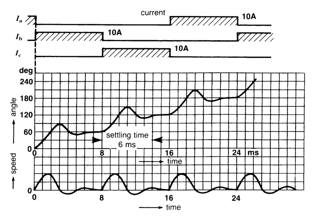
27 Figure shows current pulses Ia, Ib and Ic and instantaneous position of its rotor when motor makes one half revolution The motor is assumed to have some inertia and its driving mechanical load In the figure, duration of pulse is 8ms Hence stepping rate is 125 per sec One revolution requires 6 steps, so it takes 6/125 = sec to complete one turn Average speed is 60/0.048 = 1250rpm Stepper motor rotates in start-stop jumps
28 In start-stop operation, there is upper limit to permissable stepping rate If pulse rate of current in winding too fast, rotor may not be able to accurately follow pulses and steps will be lost To maintain synchronism rotor must be allowed to settle down before advancing to next position Refer to previous figure, interval between successive steps must be at least 6ms due to settling down of 6ms This means stepping rate limited to 167 sps
29
30 Figure shows start-stop and slewing characteristic of typical stepper motor Curve1: start-stop curve with only inertia Curve2: same as 1 but with added load inertia 2kg.cm2 Curve3: slewing curve Start-stop stepping mode sometimes referred as start without error and its characteristics shown in curve1
31 Stepper motor can be made to run at uniform speed without starting and stopping at every step = slewing mode At uniform speed, inertia effect is absent For a given stepping rate, motor can carry greater load torque when slewing Next figure shows the difference between startstop mode and slewing mode, where in both cases motor is turning at average speed of 250sps Motor will cover same number of sps, namely 1 step every 4ms but angle increases smoothly when slewing
32
33 When motor is carrying a load, it cannot suddenly go from zero to 5000sps In the same way, motor that is slewing at 5000sps cannot brought to dead stop in a step Thus to bring up motor speed ans similarly to stop a motor running at high speed, it must be accelerated/decelerated gradually-subject to condition that instantaneous position of rotor must correspond to number of pulses This process is called ramping During acceleration phase, ramping consist of progressive increase in number of driving pulse per sec Ramping usually completed in fraction of second Generated by power supply that drives the stepper motor
34 Stepper motors use either bipolar or a unipolar winding on the stator In 4-pole stator, bipolar winding consists of two coil sets A1, A2, B1 and B2 as shown in figure
35 Current Ia reverses periodically and the same goes for Ib Coils are excited by a common dc source, and because current pulses Ia and Ib must alternate, switching is required Switches are represented by Q1 to Q8 Coils can be excited sequentially in 3 different ways: Wave drive Normal drive Half-step drive Micro-step drive
36 In wave drive only one set of coils is excited at a time Below is switching sequence for cw rotation Flux produced by Ia and Ib rotates by 90deg per step Q1 Q2 on on Q3 Q4 on Q5 Q6 on Q7 Q8 on
37 In normal drive, both sets of coils are excited at a time Below is switching sequence for cw rotation Flux is oriented midway between poles as each step, however it still rotates 90deg per step Slightly greater torque than wave drive Q1 Q2 on on on Q3 Q4 on on Q5 Q6 on on on Q7 Q8 on on
38
39 Combining wave drive and normal drive Flux now rotates at 45degrees per step Main advantage: improving resolution of position tends to reduce problems of resonance Q1 Q2 On On On On Q3 Q4 On On On Q5 Q6 On On On Q7 Q8 On on On
40
41 In practice, current pulse in a winding does not rise immediately to its rated value at beginning of pulse and does not drop immediately to zero at the end of pulse interval If winding has inductance of L in henrys and resistance of R ohms, time constant T 0 equal to L/R seconds Let the coil be connected to a dc source of E volts by means of transistor A diode is connected across the windings to prevent high induced voltage from destroying the switching transistor at the moment it interrupts current flow When transistor switched on, transient current i1 reaches rated value I=E/R after 3 time constants When transistor turns line current off, transient current i2 continues to flow in coil for about 3T0 secs
42
43 Two important facts here: Current does not immediately rise to final value when transistor turned on so initial torque developed by stepper motor is smaller than normal. Rotor does not move as quickly as expected. When transistor turned off, current i2 continues to circulate in the coil/diode loop. Effective duration of pulse is Tp + 3T 0. This means we cannot switch from one coil to the next as quickly as we thought
44 Shortest possible pulse that permits the current to rise to its value I has length 6T 0. Windings of stepper motor have time constants T 0 ranging from 1ms to 8ms. Duration of steps can be no shorter than 6 x 1ms = 6ms Corresponds to 166 sps, still considered slow. One way to quicken stepping rate is to reduce T 0 by adding external resistance to motor windings and raising dc voltage so same rated of current will flow
45
46 External resistor has value 4 times of the coil resistance R, and dc voltage raised from E to 5E volts T 0 drops by factor of 5 (L/R to L/5R) hence stepping rate can be increased by the same factor Drawbacks of solution: Power supply is more expensive to deliver 5 times power Efficiency of system is low because lots of power wasted in external resistor. Fast-acting stepper motor in 100W must be driven by other means
47 The basic function of a motor driver is to provide the rated motor phase current to the motor windings in the shortest possible time. There are currently three types of motor drivers: Bilevel drivers L/R drivers PWM (Chopper) drivers
48 Bilevel drive enable us to obtain fast rise and fall times of current without using external resistors In the figure, switches Q1 and Q2 represent transistors that open and close the circuit Winding assumed to have R=0.3Ω, inductance = 2.4mH and rated current=10a Power supply is 60V with a tap at 3V Switch Q1 initially closed (a). Current pulse initiated by closing Q2 (b). Time constant for this circuit (b) is 8ms
49 Initial rate of rise corresponds to straight line OP that reaches 200A in 8ms (c). Hence current in coil rises at rate of 25000A/s Time to reach 10A is 0.4ms As soon as current reach this rated value, Q1 opens, forces current to follow new path in (d) Current is now fed by 3V source and remains fixed at 10A Current stays at this value until we want to end the pulse
50 To end pulse, we open Q2, forcing current to flow in path in (e) 57V source tries to drive current through the coil that opposite to i, thus decreasing i to zero at rate of 23750A/s. Hence current becomes zero after 0.42ms The moment current reaches zero, Q1 closes Pulse shape and Q1,Q2 switching sequence is shown in (f)
51
52
53 Chopper drives are also used in addition to bilevel drives Most stepper motors are coupled to a lead screw which permits rotary motion converted to linear displacement Suppose a stepper motor having 200 steps per revolution coupled to lead srew having pitch 5threads per inch The motor has to make 200x5 = 1000 steps to advance linearly by 1 inch Hence each step contributes displacement of 0.001in
54 Microcontroller is normally used to perform the control for the bilevel drive and chopper drive operation for the stepper motor Microcontrollers are often used to control stepper motors because: Compatible with the discrete movements of steppers Fast Can easily be programmed to work with steppers of other types Can produce the waveform used to drive small stepper motors
55 Rotation angle is proportional to number of step of input pulse Motor has full torque at standstill Precise positioning and repeatability of movement Excellent response start/stop/reverse Open loop control possible Realize a wide range of speeds Inexpensive relative to other motion control systems Easy to set up and use Overload safe. Motor cannot be damaged by mechanical overload
56 Low efficiency. Motor draws substantial power regardless of load. Torque drops rapidly with speed. No feedback to indicate missed steps. Motor gets very hot in high performance configurations. Motor is audibly very noisy at moderate to high speeds. Low output power for size and weight.
Step Motor. Mechatronics Device Report Yisheng Zhang 04/02/03. What Is A Step Motor?
 Step Motor What is a Step Motor? How Do They Work? Basic Types: Variable Reluctance, Permanent Magnet, Hybrid Where Are They Used? How Are They Controlled? How To Select A Step Motor and Driver Types of
MANTECH ELECTRONICS. Stepper Motors. Basics on Stepper Motors I. STEPPER MOTOR SYSTEMS OVERVIEW 2. STEPPING MOTORS
 MANTECH ELECTRONICS Stepper Motors Basics on Stepper Motors I. STEPPER MOTOR SYSTEMS OVERVIEW 2. STEPPING MOTORS TYPES OF STEPPING MOTORS 1. VARIABLE RELUCTANCE 2. PERMANENT MAGNET 3. HYBRID MOTOR WINDINGS
gear reduction. motor model number is determined by the following: O: Single 1: Double Motor Characteristics (1-99) Construction
 Construction") TEP OPERATIO & THEORY 1 KC tepping Motor Part umber. oncumulative positioning error (± % of step angle).. Excellent low speed/high torque characteristics without 1. tepping motor model number description
TEP OPERATIO & THEORY 1 KC tepping Motor Part umber. oncumulative positioning error (± % of step angle).. Excellent low speed/high torque characteristics without 1. tepping motor model number description
AC Motors vs DC Motors. DC Motors. DC Motor Classification ... Prof. Dr. M. Zahurul Haq
 AC Motors vs DC Motors DC Motors Prof. Dr. M. Zahurul Haq http://teacher.buet.ac.bd/zahurul/ Department of Mechanical Engineering Bangladesh University of Engineering & Technology ME 6401: Advanced Mechatronics
Note 8. Electric Actuators
 Note 8 Electric Actuators Department of Mechanical Engineering, University Of Saskatchewan, 57 Campus Drive, Saskatoon, SK S7N 5A9, Canada 1 1. Introduction In a typical closed-loop, or feedback, control
UNIT 7: STEPPER MOTORS
 UIT 7: TEPPER MOTOR 1 TEPPER MOTOR tepper motors convert digital information to mechanical motion. tepper motors rotate in distinct angular increments (steps) in response to the application of digital
QUESTION BANK SPECIAL ELECTRICAL MACHINES
 SEVENTH SEMESTER EEE QUESTION BANK SPECIAL ELECTRICAL MACHINES TWO MARK QUESTIONS 1. What is a synchronous reluctance 2. What are the types of rotor in synchronous reluctance 3. Mention some applications
Technical Reference H-37
 tepper Technical Reference H-37 tructure of tepper The figures below show two cross-sections of a.72 stepper motor. The stepper motor consists primarily of two parts: a stator and rotor. The rotor is made
HSI Stepper Motor Theory
 HI tepper Motor Theory Motors convert electrical energy into mechanical energy. A stepper motor converts electrical pulses into specific rotational movements. The movement created by each pulse is precise
Hybrid Stepper Motors
 DINGS Electrical & Mechanical Co., Ltd 3 Quality Performance Flexibility Price WHO IS DINGS? DINGS is a premier supplier of rotary and linear step motors. Based in the greater Shanghai, China area, we
Step Motors & Drives. Hybrid Step Motors
 The typical step motor system consists of a step motor and a drive package that contains the control electronics and a power supply. The drive receives step and direction signals from an indexer or programmable
COLLEGE OF ENGINEERING DEPARTMENT OF ELECTRICAL AND ELECTRONICS ENGINEERING QUESTION BANK SUBJECT CODE & NAME : EE 1001 SPECIAL ELECTRICAL MACHINES
 KINGS COLLEGE OF ENGINEERING DEPARTMENT OF ELECTRICAL AND ELECTRONICS ENGINEERING QUESTION BANK SUBJECT CODE & NAME : EE 1001 SPECIAL ELECTRICAL MACHINES YEAR / SEM : IV / VII UNIT I SYNCHRONOUS RELUCTANCE
9.9 Light Chopper Drive Motor
 9.9 Light Chopper Drive Motor This application is for a motor to drive a slotted wheel which in turn interrupts (chops) a light beam at a frequency of 200 H z. The chopper wheel has only a single slot
EEE3441 Electrical Machines Department of Electrical Engineering. Lecture. Introduction to Electrical Machines
 Department of Electrical Engineering Lecture Introduction to Electrical Machines 1 In this Lecture Induction motors and synchronous machines are introduced Production of rotating magnetic field Three-phase
Application Note : Comparative Motor Technologies
 Application Note : Comparative Motor Technologies Air Motor and Cylinders Air Actuators use compressed air to move a piston for linear motion or turn a turbine for rotary motion. Responsiveness, speed
Stepper motor From Wikipedia, the free encyclopedia
 Page 1 of 13 Stepper motor From Wikipedia, the free encyclopedia A stepper motor or step motor or stepping motor is a brushless DC electric motor that divides a full rotation into a number of equal steps.
Primer. Stepper Motors
 Primer Stepper Motors Phidgets - Primer Manual Motors Phidgets Inc. 2011 Contents 4 Introduction 5 Types of Stepper Motors 7 Controlling the Stepper Motor 9 Selecting a Gearbox 10 Glossary of Terms Introduction
Unit-IV. 1. Explain the operation, characteristics and application of DC and AC servo motor.
 Unit-IV Special Machines - Servo motor DC and AC servomotors; stepper motors variable reluctance and permanent magnet stepper motors; single phase synchronous motor reluctance motor and hysteresis motor
SOME FACTORS THAT INFLUENCE THE PERFORMANCE OF
 SOME FACTORS THAT INFLUENCE THE PERFORMANCE OF Authored By: Robert Pulford Jr. and Engineering Team Members Haydon Kerk Motion Solutions There are various parameters to consider when selecting a Rotary
Data Sheet. Size 1 and 2 Stepper Motors. 7.5 stepper motors Size 1 (RS stock no ) Size 2 (RS stock no ) Data Pack B
 Size 2 (RS stock no ) Data Pack B") Data Pack B Issued November 005 1504569 Data Sheet Size 1 and Stepper Motors 7.5 stepper motors Size 1 (S stock no. 33-947) Size (S stock no. 33-953) Two 7.5 stepper motors each with four 1Vdc windings
Data Pack B Issued November 005 1504569 Data Sheet Size 1 and Stepper Motors 7.5 stepper motors Size 1 (S stock no. 33-947) Size (S stock no. 33-953) Two 7.5 stepper motors each with four 1Vdc windings
Part- A Objective Questions (10X1=10 Marks)
") Dr. Mahalingam College of Engineering and Technology, Pollachi-3 (An Autonomous Institution) CCET 3(2016Regulation) Name of Programme: B.E. (EEE) Course Code&Course Title: 16EET41 & Synchronous & Induction
Dr. Mahalingam College of Engineering and Technology, Pollachi-3 (An Autonomous Institution) CCET 3(2016Regulation) Name of Programme: B.E. (EEE) Course Code&Course Title: 16EET41 & Synchronous & Induction
9. Define: Pull out torque of stepper motor?
 UNIT II STEPPING MOTORS PART - A 1. Define: Stepper motor? (June 14) Stepper motor is a motor which rotates step by step and not continuous rotation. When the stator is excited using a DC supply the rotor
Synchronous Motor Drives
 UNIT V SYNCHRONOUS MOTOR DRIVES 5.1 Introduction Synchronous motor is an AC motor which rotates at synchronous speed at all loads. Construction of the stator of synchronous motor is similar to the stator
EXPERIMENTAL VERIFICATION OF INDUCED VOLTAGE SELF- EXCITATION OF A SWITCHED RELUCTANCE GENERATOR
 EXPERIMENTAL VERIFICATION OF INDUCED VOLTAGE SELF- EXCITATION OF A SWITCHED RELUCTANCE GENERATOR Velimir Nedic Thomas A. Lipo Wisconsin Power Electronic Research Center University of Wisconsin Madison
Copyright Notice. Small Motor, Gearmotor and Control Handbook Copyright Bodine Electric Company. All rights reserved.
 Copyright Notice Small Motor, Gearmotor and Control Handbook Copyright 1993-2003 Bodine Electric Company. All rights reserved. Unauthorized duplication, distribution, or modification of this publication,
Introduction. Introduction. Switched Reluctance Motors. Introduction
 UNIVERSITY OF TECHNOLOGY, SYDNEY FACULTY OF ENGINEERING 48550 Electrical Energy Technology Switched Reluctance Motors Topics to cover: 1. Introduction 2. Structures & Torque Production 3. Drive Circuits
CHAPTER 6 INTRODUCTION TO MOTORS AND GENERATORS
 CHAPTER 6 INTRODUCTION TO MOTORS AND GENERATORS Objective Describe the necessary conditions for motor and generator operation. Calculate the force on a conductor carrying current in the presence of the
Electrical System Design
 Electrical System Design UNIT 4 Stepper Motors What is Stepper Motor Stepper motor is a special type of electric motor that moves in precisely defined increments of rotor position(steps). A stepper motor
Actuators are the muscles of robots.
 6.1 INTRODUCTION Actuators are the muscles of robots. Several types of actuator noteworthy? Electric motors? Servomotors? Stepper motors? Direct-drive electric motors? Hydraulic actuators? Pneumatic actuators?
Chapter 5: DC Motors. 9/18/2003 Electromechanical Dynamics 1
 Chapter 5: DC Motors 9/18/2003 Electromechanical Dynamics 1 Reversing the Rotation Direction The direction of rotation can be reversed by reversing the current flow in either the armature connection the
Principles of Electrical Engineering
 D.C GENERATORS Principle of operation of D.C machines, types of D.C Generators, e.m.f equation of D.C Generator, O.C.C of a D.C Shunt Generator, Load characteristics of D.C.Generators GENERATOR PRINCIPLE:
CHAPTER 3 DESIGN OF THE LIMITED ANGLE BRUSHLESS TORQUE MOTOR
 33 CHAPTER 3 DESIGN OF THE LIMITED ANGLE BRUSHLESS TORQUE MOTOR 3.1 INTRODUCTION This chapter presents the design of frameless Limited Angle Brushless Torque motor. The armature is wound with toroidal
MOTORS. Part 2: The Stepping Motor July 8, 2015 ELEC This lab must be handed in at the end of the lab period
 MOTORS Part 2: The Stepping Motor July 8, 2015 ELEC 3105 This lab must be handed in at the end of the lab period 1.0 Introduction The objective of this lab is to examine the operation of a typical stepping
INTRODUCTION Principle
 DC Generators INTRODUCTION A generator is a machine that converts mechanical energy into electrical energy by using the principle of magnetic induction. Principle Whenever a conductor is moved within a
INTRODUCTION TO SENSORS, TRANSDUCERS & ACTUATORS
 INTRODUCTION Transducers play a major role in mechatronics engineering & technology. These are the basic elements that convert or transform one form of energy to another form. Let us change the word energy
Creating Linear Motion One Step at a Time
 Creating Linear Motion One Step at a Time In classic mechanical engineering, linear systems are typically designed using conventional mechanical components to convert rotary into linear motion. Converting
 APGENCO/APTRANSCO Assistant Engineer Electrical Previous Question Papers Q.1 The two windings of a transformer is conductively linked. inductively linked. not linked at all. electrically linked. Q.2 A
COMPARING SLOTTED vs. SLOTLESS BRUSHLESS DC MOTORS
 COMPARING SLOTTED vs. SLOTLESS Authored By: Engineering Team Members Pittman Motors Slotless brushless DC motors represent a unique and compelling subset of motors within the larger category of brushless
Special-Purpose Electric Machines
 Special-Purpose Electric Machines The machines introduced in this lecture are used in many applications requiring fractional horsepower, or the ability to accurately control position, velocity or torque.
CHAPTER THREE DC MOTOR OVERVIEW AND MATHEMATICAL MODEL
 CHAPTER THREE DC MOTOR OVERVIEW AND MATHEMATICAL MODEL 3.1 Introduction Almost every mechanical movement that we see around us is accomplished by an electric motor. Electric machines are a means of converting
Basic Instruments Introduction Classification of instruments Operating principles Essential features of measuring
 Basic Instruments www.worldwebsites8.blogspot.com Introduction Classification of instruments Operating principles Essential features of measuring instruments PMMC Instruments Moving Iron instruments Introduction
CHAPTER 3 BRUSHLESS DC MOTOR
 53 CHAPTER 3 BRUSHLESS DC MOTOR 3.1 INTRODUCTION The application of motors has spread to all kinds of fields. In order to adopt different applications, various types of motors such as DC motors, induction
GENERATION, CONVERSION, OR DISTRIBUTION OF ELECTRIC POWER
 XXXX H02 GENERATION, CONVERSION, OR DISTRIBUTION OF ELECTRIC POWER XXXX CONTROL OR REGULATION OF ELECTRIC MOTORS, GENERATORS, OR DYNAMO-ELECTRIC CONVERTERS; CONTROLLING TRANSFORMERS, REACTORS OR CHOKE
EE6351 ELECTRIC DRIVES AND CONTROL UNIT-1 INTRODUTION
 EE6351 ELECTRIC DRIVES AND CONTROL UNIT-1 INTRODUTION 1. What is meant by drive and electric drive? Machines employed for motion control are called drives and may employ any one of the prime movers for
DHANALAKSHMI SRINIVASAN COLLEGE OF ENGINEERING AND TECHNOLOGY MAMALLAPURAM, CHENNAI
 DHANALAKSHMI SRINIVASAN COLLEGE OF ENGINEERING AND TECHNOLOGY MAMALLAPURAM, CHENNAI -603104 DEPARTMENT OF ELECTRICAL AND ELECTRONICS ENGINEERING QUESTION BANK VII SEMESTER EE6501-Power system Analysis
Technical Explanation for Inverters
 CSM_Inverter_TG_E_1_2 Introduction What Is an Inverter? An inverter controls the frequency of power supplied to an AC motor to control the rotation speed of the motor. Without an inverter, the AC motor
UNIT 2. INTRODUCTION TO DC GENERATOR (Part 1) OBJECTIVES. General Objective
 OBJECTIVES. General Objective") DC GENERATOR (Part 1) E2063/ Unit 2/ 1 UNIT 2 INTRODUCTION TO DC GENERATOR (Part 1) OBJECTIVES General Objective : To apply the basic principle of DC generator, construction principle and types of DC generator.
DC GENERATOR (Part 1) E2063/ Unit 2/ 1 UNIT 2 INTRODUCTION TO DC GENERATOR (Part 1) OBJECTIVES General Objective : To apply the basic principle of DC generator, construction principle and types of DC generator.
Unternehmensportrait. High Pole Servo. Stepper Motor basics vs. High Pole Servo
 High Pole Servo Stepper Motor basics vs High Pole Servo Stepper Motor types Hybrid-Stepper Motor Principal Construction like a BLDC (brushless DC Motor), but higher pole count Rotor and Stator silicon
Introduction to hmtechnology
 Introduction to hmtechnology Today's motion applications are requiring more precise control of both speed and position. The requirement for more complex move profiles is leading to a change from pneumatic
Most home and business appliances operate on single-phase AC power. For this reason, singlephase AC motors are in widespread use.
 Chapter 5 Most home and business appliances operate on single-phase AC power. For this reason, singlephase AC motors are in widespread use. A single-phase induction motor is larger in size, for the same
Stepper Motors ver ver.5
 A Stepper s Stepper s A-1 Overview... A-2 Overview and... A-15 & Stepper and RK Series A-16 RK... A-47... A-51 Stepper Series A-52 Stepper Series A-8 See Full Product Details Online www.orientalmotor.com
Electrical Machines II. Week 5-6: Induction Motor Construction, theory of operation, rotating magnetic field and equivalent circuit
 Electrical Machines II Week 5-6: Induction Motor Construction, theory of operation, rotating magnetic field and equivalent circuit Asynchronous (Induction) Motor: industrial construction Two types of induction
ROTATING MAGNETIC FIELD
 Chapter 5 ROTATING MAGNETIC FIELD 1 A rotating magnetic field is the key to the operation of AC motors. The magnetic field of the stator is made to rotate electrically around and around in a circle. Stator
Question Bank ( ODD)
") Programme : B.E Question Bank (2016-2017ODD) Subject Semester / Branch : EE 6703 SPECIAL ELECTRICAL MACHINES : VII-EEE UNIT - 1 PART A 1. List the applications of synchronous reluctance motors. 2. Draw
Programme : B.E Question Bank (2016-2017ODD) Subject Semester / Branch : EE 6703 SPECIAL ELECTRICAL MACHINES : VII-EEE UNIT - 1 PART A 1. List the applications of synchronous reluctance motors. 2. Draw
Electrical Machines, Drives, and Power Systems Theodore Wildi Sixth Edition
 Electrical Machines, Drives, and Power Systems Theodore Wildi Sixth Edition Pearson Education Limited Edinburgh Gate Harlow Essex CM20 2JE England and Associated Companies throughout the world Visit us
Handout Activity: HA773
 Charging system HA773-2 Handout Activity: HA773 Charging system The charging system allows for a means to recharge the battery and allow for electrical usage of components in the vehicle. The charging
HaydonKerk Motion SolutionsTM Phone: International: Stepper Motor Linear Actuators
 HaydonKerk Motion SolutionsTM www.haydonkerk.com Phone: 800.243.2715 International: 203.756.7441 Stepper Motor Linear Actuators Stepper Motor Linear Actuators: Product Summary Hybrid Linear Actuators Series
TurboDisc Stepper Motors
 TurboDisc Stepper Motors P43 P532 P31 P11 P1 The TurboDisc provides exceptional dynamic performance unparalleled by any other stepper on the market. The unique thin disc magnet enables finer step resolutions
PHY 152 (ELECTRICITY AND MAGNETISM)
") PHY 152 (ELECTRICITY AND MAGNETISM) ELECTRIC MOTORS (AC & DC) ELECTRIC GENERATORS (AC & DC) AIMS Students should be able to Describe the principle of magnetic induction as it applies to DC and AC generators.
PHY 152 (ELECTRICITY AND MAGNETISM) ELECTRIC MOTORS (AC & DC) ELECTRIC GENERATORS (AC & DC) AIMS Students should be able to Describe the principle of magnetic induction as it applies to DC and AC generators.
Ch 4 Motor Control Devices
 Ch 4 Motor Control Devices Part 1 Manually Operated Switches 1. List three examples of primary motor control devices. (P 66) Answer: Motor contactor, starter, and controller or anything that control the
Bistable Rotary Solenoid
 Bistable Rotary Solenoid The bistable rotary solenoid changes state with the application of a momentary pulse of electricity, and then remains in the changed state without power applied until a further
ECE 325 Electric Energy System Components 6 Three Phase Induction Motors. Instructor: Kai Sun Fall 2016
 ECE 325 Electric Energy System Components 6 Three Phase Induction Motors Instructor: Kai Sun Fall 2016 1 Content (Materials are from Chapters 13-15) Components and basic principles Selection and application
To discover the factors affecting the direction of rotation and speed of three-phase motors.
 EXPERIMENT 12 Direction of Rotation of Three-Phase Motor PURPOSE: To discover the factors affecting the direction of rotation and speed of three-phase motors. BRIEFING: The stators of three-phase motors
Mechatronics Chapter 10 Actuators 10-3
 MEMS1049 Mechatronics Chapter 10 Actuators 10-3 Electric Motor DC Motor DC Motor DC Motor DC Motor DC Motor Motor terminology Motor field current interaction Motor commutator It consists of a ring of
Identifying the Motorized RGS part number codes when ordering
 RGS04 Motorized with 28000 Series Size11 DS RGS04 Linear Rail for Hybird 28000 Series Size 11 Double Stacks and RGS04 for 43000 Series Size 17 Single and Double Stacks (See Page 4) RGS04 Linear Rail with
Product Manual. 42BYGH40(M)-160-4A NEMA 17 Bipolar 5.18:1. Planetary Gearbox Stepper
-160-4A NEMA 17 Bipolar 5.18:1. Planetary Gearbox Stepper") Product Manual 42BYGH40(M)-160-4A NEMA 17 Bipolar 5.18:1 Planetary Gearbox Stepper Phidgets - Product Manual 42BYGH40(M)-160-4A NEMA 17 Bipolar 5.18:1 Planetary Gearbox Stepper Phidgets Inc. 2011 Contents
Product Manual 42BYGH40(M)-160-4A NEMA 17 Bipolar 5.18:1 Planetary Gearbox Stepper Phidgets - Product Manual 42BYGH40(M)-160-4A NEMA 17 Bipolar 5.18:1 Planetary Gearbox Stepper Phidgets Inc. 2011 Contents
ELECTRO MAGNETIC INDUCTION
 6 ELECTRO MAGNETIC INDUCTION 06.01 Electromagnetic induction When the magnetic flux linked with a coil or conductor changes, an emf is developed in it. This phenomenon is known as electromagnetic induction.
3. What are the types of rotor in synchronous reluctance motor? Salient rotor Radially laminated rotor Axially laminated rotor.
 EE 2403- SPECIAL ELECTRICAL MACHINES UNIT I SYNCHRONOUS RELUCTANCE MOTOR 1. What is a synchronous reluctance motor? It is the motor driven by reluctance torque which is produced due to tendency of the
SSC-JE STAFF SELECTION COMMISSION ELECTRICAL ENGINEERING STUDY MATERIAL ELECTRICAL MACHINES
 1 SSC-JE STAFF SELECTION COMMISSION ELECTRICAL ENGINEERING STUDY MATERIAL 28-B/7, Jia Sarai, Near IIT, Hauz Khas, New Delhi-110016. Ph. 011-26514888. www.engineersinstitute.com 2 CONTENT 1. : DC MACHINE,
Doubly fed electric machine
 Doubly fed electric machine Doubly fed electric machines are electric motors or electric generators that have windings on both stationary and rotating parts, where both windings transfer significant power
UNIT-1 Drive Characteristics
 UNIT-1 Drive Characteristics DEFINITION: Systems employed for motion control are called as DRIVES Drives may employ any of the prime movers such as diesel or petrol engine, gas or steam turbines, steam
Comprehensive Technical Training
 Comprehensive Technical Training For Sugar Mills Staff on Operation & Maintenance of Baggase Based HP Cogeneration System Schedule: 10 th July to 13 th July, 2017 A.C. GENERATOR Topics Covered. Introduction.
AGN Unbalanced Loads
 Application Guidance Notes: Technical Information from Cummins Generator Technologies AGN 017 - Unbalanced Loads There will inevitably be some applications where a Generating Set is supplying power to
10. Starting Method for Induction Motors
 10. Starting Method for Induction Motors A 3-phase induction motor is theoretically self starting. The stator of an induction motor consists of 3-phase windings, which when connected to a 3-phase supply
Motor Types. Motor and Controls Introduction to Motors & Controls
 Motor and Controls www.velmex.com Motor Types MO92 MO91 PK268 These motors advance 0.9 degrees per step with half step controllers. Step accuracy is 3% noncumulative. For incremental positioning or accurate
2006 MINI Cooper S GENINFO Starting - Overview - MINI
 MINI STARTING SYSTEM * PLEASE READ THIS FIRST * 2002-07 GENINFO Starting - Overview - MINI For information on starter removal and installation, see the following articles. For Cooper, see STARTER WITH
A Practical Guide to Free Energy Devices
 A Practical Guide to Free Energy Devices Part PatD20: Last updated: 26th September 2006 Author: Patrick J. Kelly This patent covers a device which is claimed to have a greater output power than the input
Sensors & Actuators. Actuators Sensors & Actuators - H.Sarmento
 Sensors & Actuators Actuators 014-015 Sensors & Actuators - H.Sarmento Outline Mechanical actuators Electromechanical actuators Electric motors Piezo actuators 014-015 Sensors & Actuators - H.Sarmento
SECTION 4 ELECTRIC MOTORS UNIT 17: TYPES OF ELECTRIC MOTORS UNIT OBJECTIVES UNIT OBJECTIVES 3/21/2012
 SECTION 4 ELECTRIC MOTORS UNIT 17: TYPES OF ELECTRIC MOTORS UNIT OBJECTIVES After studying this unit, the reader should be able to Describe the different types of open single-phase motors used to drive
SDC,Inc. SCR-Regenerative Ac Drive
 SDC,Inc WWW.STEVENSDRIVES.COM APPLICATION NOTE #: AN_REG_GEN000 EFFECTIVE DATE: 12 MAR 02 SUPERSEDES DATE: Original NO. OF PAGES: 10 SCR-Regenerative Ac Drive Using a regeneration controller with adjustable-frequency
M2 Fractional HP Motors Performance of Reluctance, Universal and Stepper Motors
 M Fractional HP Motors Performance of Reluctance, Universal and Stepper Motors Introduction In this lab session the following motors will be studied and tested:. Synchronous Reluctance Motor.. Universal
Question 2: Around the bar magnet draw its magnetic fields. Answer:
 Chapter 13: Magnetic Effects of Electric Current Question 1: What is the reason behind the compass needle is deflected when it is brought close to the bar magnet? Compass needles work as a small bar magnet;
CHAPTER 2 MODELLING OF SWITCHED RELUCTANCE MOTORS
 9 CHAPTER 2 MODELLING OF SWITCHED RELUCTANCE MOTORS 2.1 INTRODUCTION The Switched Reluctance Motor (SRM) has a simple design with a rotor without windings and a stator with windings located at the poles.
Lower-Loss Technology
 Lower-Loss Technology FOR A STEPPING MOTOR Yasuo Sato (From the Fall 28 Technical Conference of the SMMA. Reprinted with permission of the Small Motor & Motion Association.) Management Summary The demand
14 Single- Phase A.C. Motors I
 Lectures 14-15, Page 1 14 Single- Phase A.C. Motors I There exists a very large market for single-phase, fractional horsepower motors (up to about 1 kw) particularly for domestic use. Like many large volume
Stepper Motors. By Brian Tomiuk, Jack Good, Matthew Edwards, Isaac Snellgrove. November 14th, 2018
 tepper Motors By Brian Tomiuk, Jack Good, Matthew Edwards, Isaac nellgrove November 14th, 2018 1 What is a tepper Motor? A motor whose movement is divided into discrete steps Turn 10 steps clockwise Holds
DC Motor and Generator Theory By
 DC Principles Study Unit DC Motor and Generator Theory By Robert Cecci iii Preview DC motors and generators are widely used in industrial applications. Both motors and generators are devices that produce
SMD10 SMD11 SMD15 SMD30
 SMD10 SMD11 SMD15 SMD30 Step Motor Drivers User Manual JVL Industri Elektronik A/S - January 1992 LB0009-02GB Revision 11th Feb 98 Contents 1.1 Introduction 2 1.2 Overview of Driver Models 3 1.3 Front
Pretest Module 21 Units 1-4 AC Generators & Three-Phase Motors
 Pretest Module 21 Units 1-4 AC Generators & Three-Phase Motors 1. What are the two main parts of a three-phase motor? Stator and Rotor 2. Which part of a three-phase squirrel-cage induction motor is a
5. LINEAR MOTORS 5.1 INTRODUCTION
 5.1 INTRODUCTION 5. LINEAR MOTORS Linear Electric Motors belong to the group of Special electrical machines that convert electrical energy into mechanical energy of translator motion. Linear Electric motors
SHINANO KENSHI CORP. STEPPING MOTORS DC BRUSHLESS MOTORS DC SERVO MOTORS
 SHINANO KENSHI CORP. STEPPING MOTORS DC BRUSHLESS MOTORS DC SERVO MOTORS ISO-9000 & ISO-14000 Certified Since its inception in 1918, Shinano Kenshi Co., Ltd. of Japan has found innovative and creative
Appendix A: Motion Control Theory
 Appendix A: Motion Control Theory Objectives The objectives for this appendix are as follows: Learn about valve step response. Show examples and terminology related to valve and system damping. Gain an
Sub:EE6604/DESIGN OF ELECTRICAL MACHINES Unit V SYNCHRONOUS MACHINES. 2. What are the two type of poles used in salient pole machines?
 SRI VIDYA COLLEGE OF ENGINEERING & TECHNOLOGY DEPARTMENT OF EEEE QUESTION BANK Sub:EE6604/DESIGN OF ELECTRICAL MACHINES Unit V SYNCHRONOUS MACHINES 1. Name the two types of synchronous machines. 1. Salient
Elbtalwerk GmbH. Universität Karlsruhe Elektrotechnisches Institut. Switched Reluctance Motor. Compact High-torque Electric Motor. Current.
 Elbtalwerk GmbH Switched Reluctance Motor Compact High-torque Electric Motor Current B1 Winding A1 D4 C1 C4 Pole D1 Rotation B4 A2 Rotor tooth Shaft A4 B2 Field line D3 C2 C3 D2 Stator A3 B3 Cooling air
Unit 34 Single-Phase Motors
 Unit 34 Single-Phase Motors Objectives: Unit 34 Single-Phase Motors List the different types of split-phase motors. Discuss the operation of split-phase motors. Reverse the direction of rotation of a splitphase
Design, Engineering, and Manufacturing of Motors for Electric Vehicle Applications
 Design, Engineering, and Manufacturing of Motors for Electric Vehicle Applications Mark Steffka Email: msteffka@ieee.org FR-AM-5 History of Electric Drives in Transportation 2 Why Use Electric Drives?
MOTOR TERMINAL CONNECTIONS
 MOTOR TERMINAL CONNECTIONS Motor Classification Most of the industrial machines in use today are driven by electric motors Motors are classified according to the type of power used (AC or DC) and the motors
Sensorless Brushless DC-Servomotors
 Sensorless Brushless DC-Servomotors FAULHABER Brushless DC-Servomotors are built for extreme operating conditions. They are precise, have exceptionally long lifetimes and are highly reliable. Outstanding
A Practical Guide to Free Energy Devices
 A Practical Guide to Free Energy Devices Part 16: Last updated: 28th January 2006 Author: Patrick J. Kelly Please note that this is a re-worded extract from Edwin Gray s Patent 3,890,548. It describes
The Wound-Rotor Induction Motor Part I
 Experiment 1 The Wound-Rotor Induction Motor Part I OBJECTIVE To examine the construction of the three-phase wound-rotor induction motor. To understand exciting current, synchronous speed and slip in a