9. Define: Pull out torque of stepper motor?
|
|
|
- Lynn Manning
- 5 years ago
- Views:
Transcription
1 UNIT II STEPPING MOTORS PART - A 1. Define: Stepper motor? (June 14) Stepper motor is a motor which rotates step by step and not continuous rotation. When the stator is excited using a DC supply the rotor poles align with the stator poles in opposition such that reluctance is less. 2. What are the advantages of Stepper motor? No feedback is normally required for either position control or speed control, Positional control is non cumulative, Stepping motor are compatible with modern digital equipment 3. Mention the different types of stepper motor? Variable Reluctance stepper motor (Single stack, Multi stack), Permanent magnet stepper motor, Hybrid stepper motor, Outer rotor stepper motor. 4. Mention the features of stepper motor?(dec 13) Small step angle, High positioning accuracy, High torque inertia ratio, Stepping rate, Pulse frequency 5. Define: Step Angle of stepper motor?(june 2013, Dec 13, June 2016) A stepping motor rotates through a fixed angle for every pulse. The rated value of this angle is called the step angle and expressed in degrees. 6. Define: Holding torque and Detent torque of stepper motor? (Dec 15) Holding torque is defined as the maximum static torque that can be applied to the shaft of an excited motor without causing continuous rotation. It is defined as the maximum static torque that can be applied to the shaft of an unexcited motor without causing continuous rotation. 7. Define: Resolution of stepper motor? It is defined as the accuracy of positioning of the rotor pole at a particular step angle with respect to stator pole. 8. Define: Pull in torque of stepper motor? These are alternatively called the starting characteristics and refer to the range of frictional load torque at which the motor can start and stop without loosing steps for various frequencies in a pulse strain. 9. Define: Pull out torque of stepper motor?
2 These are alternatively called the slewing characteristics. After the test, motor is started by a specified driver in the specified excitation mode in the self starting range; the pulse frequency is gradually increased; the motor will eventually run out of synchronism. The relation between the frictional load torque and the minimum pulse frequency with which the motor can synchronize is called pull out characteristics. 10. Define: Slewing frequency of stepper motor? This is defined as the maximum frequency (stepping rate) at which the loaded motor can run without losing steps is alternatively called the maximum slewing frequency. 11. Define: Stepping frequency of stepper motor? The speed of rotation of a stepping motor is given in terms of the number of steps per second and the term stepping rate is often used to indicate speed. 12. Define: Maximum starting torque of stepper motor? This is alternatively called as maximum pull in torque and is defined as the maximum frictional load with which the motor can start and synchronize with the pulse train of frequency as low as 10 Hz. 13. Why interleaving is done in a stepper motor? Interleaving is done in the stepper motor to decrease the step angle and thus increasing the resolution. 14. Explain: VR type stepper motor? It is a basic type of stepping motor in which the motor step by step rotation is achieved when the rotor teeth and stator teeth are in alignment such that the magnetic reluctance is minimized and this state provides a rest or equilibrium position. 15. Explain: PM type stepper motor? A stepping motor using permanent magnet in the rotor for step movement is called a permanent magnet motor. 16. What are the different modes of excitation?(may 12) (Dec 15) Single phase excitation, two phase excitation, Half step mode, Mini-step drive. 17. Compare closed loop control and open loop control in stepper motor.(may 12) Closed loop control is more accurate, oscillatory motions are avoided for certain speed ranges, Speed remains constant for high inertial load, follows the input pulses at stepping frequency are some of the advantages over open loop control. But it is costly and complex.
3 18. Calculate the stepping angle for a 3 phase, 24 pole permanent magnet stepper motor.(dec 12) Step angle β = 360/(no. of stator phases * no. of rotor teeth)=5º. 19. Define torque constant of a stepper motor.(dec 12) The torque constant of the stepper motor is defined as the initial slope of the torque current curve of the stepper motor. 20. What is the function of driver circuit in stepper motor. (June 13) The stepper motor is a digital device that needs binary signals for its operation. The power driver is essentially a current amplifier, since the sequence generator can supply only logic but not any power. 21. Give the difference between single and multi stack stepping motors?(june 14) Sl.No Single Stack Stepper Motor Multi Stack Stepper Motor 1 The number of stator poles should be different that of the rotor poles in order to have self starting capability and bidirectional rotation. 2 In single stack each and every stator pole carries a field coil. The stator and rotor have same number of poles and same pole pitch. It is used to obtain small step sizes. It consist of m identical single stack variable reluctance motor with the rotor mounts on the single shaft. 22. Distinguish the half step and full step operation of a stepper motor.(dec 14) SL.NO HALF STEP OPERATION FULL STEP OPERATION 1 It is defined as the alternate one phase on and two phase on mode operation. 2 Rotor rotates on each step angle is half of the full step angle. It is the one phase on mode operation.it means at that time only one winding is energized. By energizing one stator winding the rotor rotates at some angle.it s full step operating. 23. Define the micro stepping mode of stepper motor. (May 15)
4 Micro stepping means, the step angle of the VR stepper motor is very small. It is also called mini stepping. It can be achieved by two phases simultaneously as in 2 phases on mode but with two currents deliberately made unequal. 24. Name the various driver circuits used in stepper motor. (May 15, June 2016) Driver circuit for stepper motor are broadly classified in to Unipolar and Bipolar driver circuits. Based on the supply voltage given to stator windings they are classified as L/R driver circuit, Chopper drive circuit, H bridge drive circuit. 25. Define: Maxwell s stress It is defined as curving of magnetic lines of force at the end of the poles of the stator when rotor rotates. 26. Define Lead angle(dec 2016) The angle difference between the phase to be de-energized to bring the stepper motor to the position of equilibrium (stopping the motor) and energization of next phase winding to start the motor during closed loop operation is known as lead angle. The relation between the rotor s present position and the phase to be excited specified in terms of lead angle. 27. What is the need for suppressor circuits in stepper motor? (Dec 2016) The suppressor circuits are needed to ensure the fast decay of current through the winding whn it is turned off Part B 1. Explain the construction and principle of operation of Variable Reluctance Stepping motor? (May 12, Dec 12, Dec 13,June 14 )( Working of Single stack type and multi stack type( June 13, June 2016))(Micro stepping Dec 13) Variable Reluctance Stepping motor: 1. Single stack type, 2.multi stack type(refer 10) Construction:
5 The variable reluctance motor does not use a permanent magnet. As a result, the motor rotor can move without constraint or "detent" torque. This type of construction is good in non industrial applications that do not require a high degree of motor torque, such as the positioning of a micro slide. The variable reluctance motor in the above illustration has four "stator pole sets" (A, B, C) set 15 degrees apart. Current applied to pole A through the motor winding causes a magnetic attraction that aligns the rotor (tooth) to pole A. Energizing stator pole B causes the rotor to rotate 15 degrees in alignment with pole B. This process will continue with pole C and back to A in a clockwise direction. Reversing the procedure (C to A) would result in a counterclockwise rotation. If your motor has three windings, typically connected as shown in the schematic diagram in Figure, with one terminal common to all windings, it is most likely a variable reluctance stepping motor. In use, the common wire typically goes to the positive supply and the windings are energized in sequence. The cross section shown in Figure is of 30 degree per step variable reluctance motor. The rotor in this motor has 4 teeth and the stator has 6 poles, with each winding wrapped around two opposite poles. With winding number 1 energized, the rotor teeth marked X are attracted to this winding's poles. If the current through winding 1 is turned off and winding 2 is turned on, the rotor will rotate 30 degrees clockwise so that the poles marked Y line up with the poles marked 2. To rotate this motor continuously, we just apply power to the 3 windings in sequence. Assuming positive logic, where a 1 means turning on the current through a motor winding, the following control sequence will spin the motor illustrated in Figure 2.6 clockwise 24 steps or 2 revolutions: Winding Winding Winding time ---> There are also variable reluctance stepping motors with 4 and 5 windings, requiring 5 or 6 wires. The principle for driving these motors is same as that for the three winding motors, but it becomes important to work out the correct order to energize the windings to make the motor step nicely. Principle of operation: One phase on or full step operation, 2 phase on mode, half step operation, micro stepping. 2. Explain the construction and operation of hybrid Stepping motor? (Dec 14) Hybrid motors combine the best characteristics of the variable reluctance and permanent magnet motors. They are constructed with multi-toothed stator poles and a permanent magnet rotor. Standard hybrid motors have 200 rotor teeth and rotate at 1.80

(May 12)(June 14, Dec 2016, June 2016) There are two characteristics- torque displacement characteristics,")
6 step angles. Other hybrid motors are available in 0.9ºand 3.6º step angle configurations. Because they exhibit high static and dynamic torque and run at very high step rates, hybrid motors are used in a wide variety of industrial applications. 3.Discuss the static and dynamic characteristics of stepper motor with neat sketch? (June 14)(May 12)(June 14, Dec 2016, June 2016) There are two characteristics- torque displacement characteristics, torque current characteristics
7
8 Dynamic characterictics: At low stepping rates, the rise and fall times of the current through the motor windings has little effect on the motor's performance, but at higher speeds, the effect of the inductance of the motor windings is to reduce the available torque, as shown in Figure
9 Torque Normal mode Slewing mode Speed An ideal torque-speed characteristic for a stepper motor 2 distinct modes of operation: Locked-step (normal) mode Slewing mode In the first, the rotor comes to rest between steps (mode commonly used to achieve a given rotor position); rotor can be started, stopped, reversed Slewing mode does not allow stopping or reversal of the rotor, although it advances in synchronism with the stepping sequence (e.g. rewinding a tape drive) Torque Curve A: Pull-out torque Curve B: Pull-in torque Curve B Curve A Normal mode Slewing mode Pull-in rate Max pull-in rate Pull-out rate Speed Max pull-out rate The motor's maximum speed is defined as the speed at which the available torque falls to zero. Measuring maximum speed can be difficult when there are resonance problems, because these cause the torque to drop to zero prematurely. The cutoff speed is the speed above which the torque begins to fall. When the motor is operating below its cutoff speed, the rise and fall times of the current through the motor windings occupy an
10 insignificant fraction of each step, while at the cutoff speed, the step duration is comparable to the sum of the rise and fall times. Note that a sharp cutoff is rare, and therefore, statements of a motor's cutoff speed are, of necessity, approximate. The details of the torque versus speed relationship depend on the details of the rise and fall times in the motor windings, and these depend on the motor control system as well as the motor. Therefore, the cutoff speed and maximum speed for any particular motor depend, in part, on the control system! The torque versus speed curves published in motor data sheets occasionally come with documentation of the motor controller used to obtain that curve, but this is far from universal practice! Similarly, the resonant speed depends on the moment of inertia of the entire rotating system, not just the motor rotor, and the extent to which the torque drops at resonance depends on the presence of mechanical damping and on the nature of the control system. Some published torque versus speed curves show very clear resonances without documenting the moment of inertia of the hardware that may have been attached to the motor shaft in order to make torque measurements. The torque versus speed curve shown in Figure is typical of the simplest of control systems. More complex control systems sometimes introduce electronic resonances that act to increase the available torque above the motor's low-speed torque. A common result of this is a peak in the available torque near the cutoff speed. Characteristic Parameters Holding torque: the maximum torque which can be applied to an energized stationary motor without causing spindle rotation Pull-out torque: the maximum torque which can be applied to a motor, running at a given stepping rate, without losing synchronism Pull-in torque: the maximum torque against which a motor will start, at a given pulse rate, and reach synchronism without losing a step. Pull-out rate: the maximum switching rate at which a motor will remain in synchronism while the switching rate is gradually increased. Pull-in rate: the maximum switching rate at which a loaded motor can start without losing steps Slew range: the range of switching rates between pull-in and pull-out in which a motor will run in synchronism but cannot start or reverse. There are following two modes of operation with regards to dynamic characteristics start stop mode, slewing mode 4. Explain in detail the drive system of a stepping motor? (May 12, Dec 12,Dec 14,June 14) There are two main drive circuits for stepper motors, namely; Uni-polar and Bi-polar drive circuits.
 pulses to run the motor.")
11 Uni-polar Drive Circuit Uni-polar drive circuit for three-phase variable reluctance stepper motor Bi-polar Drive Circuit One phase of a Bi-polar drive circuit for permanent magnet or hybrid stepper motors DRIVERS The stepper motor driver receives low-level signals from the indexer or control system and converts them into electrical (step) pulses to run the motor. One step pulse is required for every step of the motor shaft. In full step mode, with a standard 200 step motor, 200 step pulses are required to complete one revolution. Likewise, in microstepping mode the driver may be required to generate 50,000 or more step pulses per revolution. TYPES OF STEP MOTOR DRIVERS For industrial applications there are basically three types of driver technologies. They all utilize a "translator" to convert the step and direction signals from the indexer into electrical pulses to the motor. The essential difference is in the way they energize the motor winding. The circuit that performs this task is known as the "switch set."
12 UNIPOLAR The name unipolar is derived from the fact that current flow is limited to one direction. As such, the switch set of a unipolar drive is fairly simple and inexpensive. The drawback to using a unipolar drive however, is its limited capability to energize all the windings at any one time. As a result, the number of amp turns (torque) is reduced by nearly 40% compared to other driver technologies. Unipolar drivers are good for applications that operate at relatively low step rates. R/L R/L (resistance/limited) drivers are, by today's standards, old technology but still exist in some (low power) applications because they are simple and inexpensive. The drawback to using R/L drivers is that they rely on a "dropping resistor" to get almost 10 times the amount of motor current rating necessary to maintain a useful increase in speed. This process also produces an excessive amount of heat and must rely on a DC power supply for its current source. BIPOLAR CHOPPER Bipolar chopper drivers are by far the most widely used drivers for industrial applications. Although they are typically more expensive to design, they offer high performance and high efficiency. Bipolar chopper drivers use an extra set of switching transistors to eliminate the need for two power sources. Additionally, these drivers use a four transistor bridge with recirculating diodes and a sense resistor that maintains a feedback voltage proportional to the motor current. Motor windings, using a bipolar chopper driver, are energized to the full supply level by turning on one set (top and bottom) of the switching transistors. The sense resistor monitors the linear rise in current until the required level is reached. At this point the top switch opens and the current in the motor coil is maintained via the bottom switch and the diode. Current "decay" (lose over time) occurs until a preset position is reached and the process starts over. This "chopping" effect of the supply is what maintains the correct current voltage to the motor at all times. In the below circuits, the details of the necessary switches have been deliberately ignored. Any switching technology, from toggle switches to power MOSFETS will work! Figure contains some suggestions for implementing each switch, with a motor winding and protection diode included for orientation purposes:
13 Each of the switches shown in Figure is compatible with a TTL input. The 5 volt supply used for the logic, including the 7407 open-collector driver used in the figure, should be well regulated. The motor power, typically between 5 and 24 volts, needs only minimal regulation. It is worth noting that these power switching circuits are appropriate for driving solenoids, DC motors and other inductive loads as well as for driving stepping motors. ` The SK3180 transistor shown in Figure is a power darlington with a current gain over 1000; thus, the 10 milliamps flowing through the 470 ohm bias resistor is more than enough to allow the transistor to switch a few amps current through the motor winding. The 7407 buffer used to drive the Darlington may be replaced with any high-voltage open collector chip that can sink at least 10 milliamps. In the event that the transistor fails, the high-voltage open collector driver serves to protect the rest of the logic circuitry from the motor power supply. The IRC IRL540 shown in Figure is a power field effect transistor. This can handle currents of up to about 20 amps, and it breaks down nondestructively at 100 volts; as a result, this chip can absorb inductive spikes without protection diodes if it is attached to a large enough heat sink. This transistor has a very fast switching time, so the protection diodes must be comparably fast or bypassed by small capacitors. This is particularly essential with the diodes used to protect the transistor against reverse bias! In the event that the transistor fails, the zener diode and 100 ohm resistor protect the TTL circuitry. The 100 ohm resistor also acts to somewhat slow the switching times on the transistor. For applications where each motor winding draws under 500 milliamps, the ULN200x family of darlington arrays from Allegro Microsystems, also available as the DS200x from National Semiconductor and as the Motorola MC1413 darlington array will drive multiple motor windings or other inductive loads directly from logic inputs. Figure 3.8 shows the pin out of the widely available ULN2003 chip, an array of 7 darlington transistors with TTL compatible inputs:
14 The base resistor on each darlington transistor is matched to standard bipolar TTL outputs. Each NPN darlington is wired with its emitter connected to pin 8, intended as a ground pin, Each transistor in this package is protected by two diodes, one shorting the emitter to the collector, protecting against reverse voltages across the transistor, and one connecting the collector to pin 9; if pin 9 is wired to the positive motor supply, this diode will protect the transistor against inductive spikes. The ULN2803 chip is essentially the same as the ULN2003 chip described above, except that it is in an 18-pin package, and contains 8 darlingtons, allowing one chip to be used to drive a pair of common unipolar permanent-magnet or variable-reluctance motors. For motors drawing under 600 milliamps per winding, the UDN2547B quad power driver made by Allegro Microsystems will handle all 4 windings of common unipolar stepping motors. For motors drawing under 300 milliamps per winding, Texas Instruments SN7541, 7542 and 7543 dual power drivers are a good choice; both of these alternatives include some logic with the power drivers. 5.Explain in detail the multi stack Variable Reluctance Stepping motor?(june 13, Dec 2016,June 2016) Multi-Stack Variable Reluctance Stepper Motors Cross section view of a typical three-stack variable reluctance stepper motor
15 Teeth position for a 3-phase, 4-pole, 12-teeth, three-stack, variable reluctance stepper motor when phase a is energized The VR stepper motors mentioned up to this point are all single-stack motors. That is, all the phases are arranged in a single stack, or plane. The disadvantage of this design for a stepper motor is that the steps are generally quite large (above 15 ). Multi-stack stepper motors can produce smaller step sizes because the motor is divided along its axial length into magnetically isolated sections, or stacks. Each of these sections is excited by a separate winding, or phase. In this type of motor, each stack corresponds to a phase, and the stator and rotor have the same tooth pitch. 6. What is the motor torque Tm required to accelerate an initial load of 3x10⁻⁴ kg m 2 from f1 = 1000Hz to f2 = 2000Hz during 100msec. The frictional torque Tf is 0.05 Nm and the step angle is T L2Ti ( t)sint 2 7.With a neat block diagram, explain the closed loop operation of stepping motor. (June 13) 8.a Explain the concept of torque production in variable reluctance stepping motor.(dec 13)
16 Let e(t) = voltage applied per stack R = winding resistance per stack L(θ) = winding inductance per stack (a function of rotor position only and independent of coil current because of linear magnetic circuit assumption) i(t) = current per stack θ(t) = angular position of rotor d Kirchoff s mesh equation for stator winding is e( t) Ri( t) dt where λ = flux linkages of stator winding = il(θ). Therefore, di dl( ) d Ri( t) L( ) i...(1) dt d dt Transformer emf speed emf Energy stored in air gap is W = ½ L(θ) i 2 (t)..(2) Mechanical torque developed is given by T W ( i, ) 1 2 dl( ) i () t...(3) 2 d Rotor dynamics is governed by 2 d d T J f.(4) 2 dt dt In a toothed structure, reluctance and therefore winding inductance varies continuously (even function) as function of θ over and above an average value, i.e., L( ) L L cost.(5) 1 2 Substituting in equation 3, 1 2 T L2Ti ( t)sint 2 8.b.A single stack, 3-phase variable reluctance motor has a step angle of 15º. Find the number of stator and rotor poles. (Dec12) Nr=8, when Ns>Nr, Ns=12, when Ns<Nr, Ns=6 9. What is the motor torque Tm required to accelerate an initial load of 2x10⁻⁴ kgm 2 from 500Hz to 1500Hz in 50 ms. the frictional torque is 0.03 Nm and step angle is 1.18º. (Dec 12)
17 1 2 2 T L2Ti ( t)sint 10. a.with a neat block diagram explain microprocessor control of stepper motor (June 2013) A positional signal is feedback to the block of hardware which monitors the rotor movement and exchanges information with the microprocessor. The software must be programmed so that the microprocessor determines better timings for changing lead angles. b. What are the advantages of closed loop control of stepper motor. Closed loop control is more accurate, oscillatory motions are avoided for certain speed ranges, Speed remains constant for high inertial load, follows the input pulses at stepping frequency are some of the advantages over open loop control.
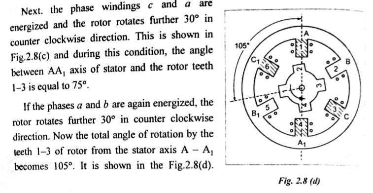
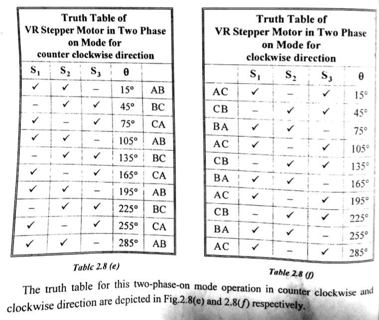
18 11.Explain the modes of excitation of a stepper motor with neat diagram(dec 2016)


19
20


21
22

23
24


25
 Solution: Ressolution = 180 steps/rev Required motor speed = 2400 rpm Speed in rps (n) = Speed in rpm/60 = 2400/60 Speed in")
26 12. A stepper motor has resolution of 180 steps/rev. Find the pulse rate required in order to obtain a speed of 2400rpm. (Dec 2016) Solution: Ressolution = 180 steps/rev Required motor speed = 2400 rpm Speed in rps (n) = Speed in rpm/60 = 2400/60 Speed in rps (n) = 40 rps
27 Step angle (β) = / (Number of steps/ rev) = 360/180 β = 2 0 From the expression, n = (β*f)/ f = (n *360)/ β f = ( 40*360)/2 f = 7200 pps
MANTECH ELECTRONICS. Stepper Motors. Basics on Stepper Motors I. STEPPER MOTOR SYSTEMS OVERVIEW 2. STEPPING MOTORS
 MANTECH ELECTRONICS Stepper Motors Basics on Stepper Motors I. STEPPER MOTOR SYSTEMS OVERVIEW 2. STEPPING MOTORS TYPES OF STEPPING MOTORS 1. VARIABLE RELUCTANCE 2. PERMANENT MAGNET 3. HYBRID MOTOR WINDINGS
QUESTION BANK SPECIAL ELECTRICAL MACHINES
 SEVENTH SEMESTER EEE QUESTION BANK SPECIAL ELECTRICAL MACHINES TWO MARK QUESTIONS 1. What is a synchronous reluctance 2. What are the types of rotor in synchronous reluctance 3. Mention some applications
gear reduction. motor model number is determined by the following: O: Single 1: Double Motor Characteristics (1-99) Construction
 Construction") TEP OPERATIO & THEORY 1 KC tepping Motor Part umber. oncumulative positioning error (± % of step angle).. Excellent low speed/high torque characteristics without 1. tepping motor model number description
TEP OPERATIO & THEORY 1 KC tepping Motor Part umber. oncumulative positioning error (± % of step angle).. Excellent low speed/high torque characteristics without 1. tepping motor model number description
Prepared By: Ahmad Firdaus Bin Ahmad Zaidi
 Prepared By: Ahmad Firdaus Bin Ahmad Zaidi A stepper motor is an electromechanical device which converts electrical pulses into discrete mechanical rotational movements. Stepper motor mainly used when
COLLEGE OF ENGINEERING DEPARTMENT OF ELECTRICAL AND ELECTRONICS ENGINEERING QUESTION BANK SUBJECT CODE & NAME : EE 1001 SPECIAL ELECTRICAL MACHINES
 KINGS COLLEGE OF ENGINEERING DEPARTMENT OF ELECTRICAL AND ELECTRONICS ENGINEERING QUESTION BANK SUBJECT CODE & NAME : EE 1001 SPECIAL ELECTRICAL MACHINES YEAR / SEM : IV / VII UNIT I SYNCHRONOUS RELUCTANCE
Step Motor. Mechatronics Device Report Yisheng Zhang 04/02/03. What Is A Step Motor?
 Step Motor What is a Step Motor? How Do They Work? Basic Types: Variable Reluctance, Permanent Magnet, Hybrid Where Are They Used? How Are They Controlled? How To Select A Step Motor and Driver Types of
DHANALAKSHMI SRINIVASAN COLLEGE OF ENGINEERING AND TECHNOLOGY MAMALLAPURAM, CHENNAI
 DHANALAKSHMI SRINIVASAN COLLEGE OF ENGINEERING AND TECHNOLOGY MAMALLAPURAM, CHENNAI -603104 DEPARTMENT OF ELECTRICAL AND ELECTRONICS ENGINEERING QUESTION BANK VII SEMESTER EE6501-Power system Analysis
Question Bank ( ODD)
") Programme : B.E Question Bank (2016-2017ODD) Subject Semester / Branch : EE 6703 SPECIAL ELECTRICAL MACHINES : VII-EEE UNIT - 1 PART A 1. List the applications of synchronous reluctance motors. 2. Draw
Programme : B.E Question Bank (2016-2017ODD) Subject Semester / Branch : EE 6703 SPECIAL ELECTRICAL MACHINES : VII-EEE UNIT - 1 PART A 1. List the applications of synchronous reluctance motors. 2. Draw
Electrical System Design
 Electrical System Design UNIT 4 Stepper Motors What is Stepper Motor Stepper motor is a special type of electric motor that moves in precisely defined increments of rotor position(steps). A stepper motor
AC Motors vs DC Motors. DC Motors. DC Motor Classification ... Prof. Dr. M. Zahurul Haq
 AC Motors vs DC Motors DC Motors Prof. Dr. M. Zahurul Haq http://teacher.buet.ac.bd/zahurul/ Department of Mechanical Engineering Bangladesh University of Engineering & Technology ME 6401: Advanced Mechatronics
HSI Stepper Motor Theory
 HI tepper Motor Theory Motors convert electrical energy into mechanical energy. A stepper motor converts electrical pulses into specific rotational movements. The movement created by each pulse is precise
Note 8. Electric Actuators
 Note 8 Electric Actuators Department of Mechanical Engineering, University Of Saskatchewan, 57 Campus Drive, Saskatoon, SK S7N 5A9, Canada 1 1. Introduction In a typical closed-loop, or feedback, control
B.E-EEE(Marine) Batch 7. Subject Code EE1704 Subject Name Special Electrical Machines
 Batch 7. Subject Code EE1704 Subject Name Special Electrical Machines") Course B.E-EEE(Marine) Batch 7 Semester VII Subject Code EE1704 Subject Name Special Electrical Machines Part-A Unit-1 1 List the applications of synchronous reluctance motors. 2 Draw the voltage and torque
Course B.E-EEE(Marine) Batch 7 Semester VII Subject Code EE1704 Subject Name Special Electrical Machines Part-A Unit-1 1 List the applications of synchronous reluctance motors. 2 Draw the voltage and torque
9.9 Light Chopper Drive Motor
 9.9 Light Chopper Drive Motor This application is for a motor to drive a slotted wheel which in turn interrupts (chops) a light beam at a frequency of 200 H z. The chopper wheel has only a single slot
Hybrid Stepper Motors
 DINGS Electrical & Mechanical Co., Ltd 3 Quality Performance Flexibility Price WHO IS DINGS? DINGS is a premier supplier of rotary and linear step motors. Based in the greater Shanghai, China area, we
UNIT 7: STEPPER MOTORS
 UIT 7: TEPPER MOTOR 1 TEPPER MOTOR tepper motors convert digital information to mechanical motion. tepper motors rotate in distinct angular increments (steps) in response to the application of digital
MOTORS. Part 2: The Stepping Motor July 8, 2015 ELEC This lab must be handed in at the end of the lab period
 MOTORS Part 2: The Stepping Motor July 8, 2015 ELEC 3105 This lab must be handed in at the end of the lab period 1.0 Introduction The objective of this lab is to examine the operation of a typical stepping
Actuators are the muscles of robots.
 6.1 INTRODUCTION Actuators are the muscles of robots. Several types of actuator noteworthy? Electric motors? Servomotors? Stepper motors? Direct-drive electric motors? Hydraulic actuators? Pneumatic actuators?
CHAPTER 2 MODELLING OF SWITCHED RELUCTANCE MOTORS
 9 CHAPTER 2 MODELLING OF SWITCHED RELUCTANCE MOTORS 2.1 INTRODUCTION The Switched Reluctance Motor (SRM) has a simple design with a rotor without windings and a stator with windings located at the poles.
Chapter 5. Design of Control Mechanism of Variable Suspension System. 5.1: Introduction: Objective of the Mechanism:
 123 Chapter 5 Design of Control Mechanism of Variable Suspension System 5.1: Introduction: Objective of the Mechanism: In this section, Design, control and working of the control mechanism for varying
Introduction. Introduction. Switched Reluctance Motors. Introduction
 UNIVERSITY OF TECHNOLOGY, SYDNEY FACULTY OF ENGINEERING 48550 Electrical Energy Technology Switched Reluctance Motors Topics to cover: 1. Introduction 2. Structures & Torque Production 3. Drive Circuits
Creating Linear Motion One Step at a Time
 Creating Linear Motion One Step at a Time In classic mechanical engineering, linear systems are typically designed using conventional mechanical components to convert rotary into linear motion. Converting
KINGS COLLEGE OF ENGINEERING DEPARTMENT OF ELECTRICAL AND ELECTRONICS ENGINEERING QUESTION BANK
 KINGS COLLEGE OF ENGINEERING DEPARTMENT OF ELECTRICAL AND ELECTRONICS ENGINEERING QUESTION BANK NAME OF THE SUBJECT: EE 1001 SPECIAL ELECTRICAL MACHINES YEAR / SEM : IV / VII UNIT- I AC COMMUTATOR MOTORS
Mathematical Modeling and Simulation of Switched Reluctance Motor
 Mathematical Modeling and Simulation of Switched Reluctance Motor Vikramarajan Jambulingam Electrical and Electronics Engineering, VIT University, India. Abstract: The SRM motors are simple in construction
Step Motors & Drives. Hybrid Step Motors
 The typical step motor system consists of a step motor and a drive package that contains the control electronics and a power supply. The drive receives step and direction signals from an indexer or programmable
Stepper motor From Wikipedia, the free encyclopedia
 Page 1 of 13 Stepper motor From Wikipedia, the free encyclopedia A stepper motor or step motor or stepping motor is a brushless DC electric motor that divides a full rotation into a number of equal steps.
CHAPTER THREE DC MOTOR OVERVIEW AND MATHEMATICAL MODEL
 CHAPTER THREE DC MOTOR OVERVIEW AND MATHEMATICAL MODEL 3.1 Introduction Almost every mechanical movement that we see around us is accomplished by an electric motor. Electric machines are a means of converting
SOME FACTORS THAT INFLUENCE THE PERFORMANCE OF
 SOME FACTORS THAT INFLUENCE THE PERFORMANCE OF Authored By: Robert Pulford Jr. and Engineering Team Members Haydon Kerk Motion Solutions There are various parameters to consider when selecting a Rotary
EXPERIMENTAL VERIFICATION OF INDUCED VOLTAGE SELF- EXCITATION OF A SWITCHED RELUCTANCE GENERATOR
 EXPERIMENTAL VERIFICATION OF INDUCED VOLTAGE SELF- EXCITATION OF A SWITCHED RELUCTANCE GENERATOR Velimir Nedic Thomas A. Lipo Wisconsin Power Electronic Research Center University of Wisconsin Madison
Technical Reference H-37
 tepper Technical Reference H-37 tructure of tepper The figures below show two cross-sections of a.72 stepper motor. The stepper motor consists primarily of two parts: a stator and rotor. The rotor is made
2014 ELECTRICAL TECHNOLOGY
 SET - 1 II B. Tech I Semester Regular Examinations, March 2014 ELECTRICAL TECHNOLOGY (Com. to ECE, EIE, BME) Time: 3 hours Max. Marks: 75 Answer any FIVE Questions All Questions carry Equal Marks ~~~~~~~~~~~~~~~~~~~~~~~~~~
Primer. Stepper Motors
 Primer Stepper Motors Phidgets - Primer Manual Motors Phidgets Inc. 2011 Contents 4 Introduction 5 Types of Stepper Motors 7 Controlling the Stepper Motor 9 Selecting a Gearbox 10 Glossary of Terms Introduction
BELT-DRIVEN ALTERNATORS
 CHAPTER 13 BELT-DRIVEN ALTERNATORS INTRODUCTION A generator is a machine that converts mechanical energy into electrical energy using the principle of magnetic induction. This principle is based on the
INSTITUTE OF AERONAUTICAL ENGINEERING Dundigal, Hyderabad
 INSTITUTE OF AERONAUTICAL ENGINEERING Dundigal, Hyderabad - 500 043 MECHANICAL ENGINEERING ASSIGNMENT Name : Electrical and Electronics Engineering Code : A40203 Class : II B. Tech I Semester Branch :
3. What are the types of rotor in synchronous reluctance motor? Salient rotor Radially laminated rotor Axially laminated rotor.
 EE 2403- SPECIAL ELECTRICAL MACHINES UNIT I SYNCHRONOUS RELUCTANCE MOTOR 1. What is a synchronous reluctance motor? It is the motor driven by reluctance torque which is produced due to tendency of the
Special-Purpose Electric Machines
 Special-Purpose Electric Machines The machines introduced in this lecture are used in many applications requiring fractional horsepower, or the ability to accurately control position, velocity or torque.
TurboDisc Stepper Motors
 TurboDisc Stepper Motors P43 P532 P31 P11 P1 The TurboDisc provides exceptional dynamic performance unparalleled by any other stepper on the market. The unique thin disc magnet enables finer step resolutions
Today s lecture: Generators Eddy Currents Self Inductance Energy Stored in a Magnetic Field
 PHYSICS 1B Today s lecture: Generators Eddy Currents Self Inductance Energy Stored in a Magnetic Field PHYSICS 1B Lenz's Law Generators Electric generators take in energy by work and transfer it out by
SHINANO KENSHI CORP. STEPPING MOTORS DC BRUSHLESS MOTORS DC SERVO MOTORS
 SHINANO KENSHI CORP. STEPPING MOTORS DC BRUSHLESS MOTORS DC SERVO MOTORS ISO-9000 & ISO-14000 Certified Since its inception in 1918, Shinano Kenshi Co., Ltd. of Japan has found innovative and creative
Data Sheet. Size 1 and 2 Stepper Motors. 7.5 stepper motors Size 1 (RS stock no ) Size 2 (RS stock no ) Data Pack B
 Size 2 (RS stock no ) Data Pack B") Data Pack B Issued November 005 1504569 Data Sheet Size 1 and Stepper Motors 7.5 stepper motors Size 1 (S stock no. 33-947) Size (S stock no. 33-953) Two 7.5 stepper motors each with four 1Vdc windings
Data Pack B Issued November 005 1504569 Data Sheet Size 1 and Stepper Motors 7.5 stepper motors Size 1 (S stock no. 33-947) Size (S stock no. 33-953) Two 7.5 stepper motors each with four 1Vdc windings
Simulation and Development of Stepper Motor for Badminton Playing Robot
 International OPEN ACCESS Journal Of Modern Engineering Research (IJMER) Simulation and Development of Stepper Motor for Badminton Playing Robot Rupesh Borkar 1, Tanveer Aga 2 1 Electrical Department,
User Manual. Model P403. High Performance Microstepping Driver
 User Manual Model P403 High Performance Microstepping Driver 1. General The P403 is a high performance microstepping driver based on the most advanced technology in the world today. It is suitable for
Unit-IV. 1. Explain the operation, characteristics and application of DC and AC servo motor.
 Unit-IV Special Machines - Servo motor DC and AC servomotors; stepper motors variable reluctance and permanent magnet stepper motors; single phase synchronous motor reluctance motor and hysteresis motor
SDC,Inc. SCR-Regenerative Ac Drive
 SDC,Inc WWW.STEVENSDRIVES.COM APPLICATION NOTE #: AN_REG_GEN000 EFFECTIVE DATE: 12 MAR 02 SUPERSEDES DATE: Original NO. OF PAGES: 10 SCR-Regenerative Ac Drive Using a regeneration controller with adjustable-frequency
Design and Finite Element Analysis of Hybrid Stepper Motor for Spacecraft Applications
 Design and Finite Element Analysis of Hybrid Stepper Motor for Spacecraft Applications Praveen R.P., Ravichandran M.H., V. T. Sadasivan Achari, Dr.Jagathy Raj V. P., Dr.G.Madhu and Dr.G.R. Bindu 6 Abstract
Mechatronics Chapter 10 Actuators 10-3
 MEMS1049 Mechatronics Chapter 10 Actuators 10-3 Electric Motor DC Motor DC Motor DC Motor DC Motor DC Motor Motor terminology Motor field current interaction Motor commutator It consists of a ring of
2. Draw the speed-torque characteristics of dc shunt motor and series motor. (May2013) (May 2014)
 (May 2014)") UNIT 2 - DRIVE MOTOR CHARACTERISTICS PART A 1. What is meant by mechanical characteristics? A curve is drawn between speed-torque. This characteristic is called mechanical characteristics. 2. Draw the
UNIT 2 - DRIVE MOTOR CHARACTERISTICS PART A 1. What is meant by mechanical characteristics? A curve is drawn between speed-torque. This characteristic is called mechanical characteristics. 2. Draw the
Introduction - Why Brushless? (Cont( Introduction. Brushless DC Motors. Introduction Electromechanical Systems
 UNIVERSITY OF TECHNOLOGY, SYDNEY FACULTY OF ENGINEERING 48531 Electromechanical Systems Brushless DC Motors Topics to cover: 1. 2. Structures & Drive Circuits 3. Equivalent Circuit 4. Performance - Why
2 Principles of d.c. machines
 2 Principles of d.c. machines D.C. machines are the electro mechanical energy converters which work from a d.c. source and generate mechanical power or convert mechanical power into a d.c. power. These
) and the rotor position (f r
 and the rotor position (f r") Microstepping This application note discusses microstepping and the increased system performance that it offers. Some of the most important factors that limit microstepping performance, as well as methods
Microstepping This application note discusses microstepping and the increased system performance that it offers. Some of the most important factors that limit microstepping performance, as well as methods
Lecture 2. Power semiconductor devices (Power switches)
") Lecture 2. Power semiconductor devices (Power switches) Power semiconductor switches are the work-horses of power electronics (PE). There are several power semiconductors devices currently involved in
Lecture 2. Power semiconductor devices (Power switches) Power semiconductor switches are the work-horses of power electronics (PE). There are several power semiconductors devices currently involved in
DMX-A2-DRV Integrated Advanced Step Motor Driver
 DMX-A2-DRV Integrated Advanced Step Motor Driver DMX-A2-DRV Manual page 1 rev 3.10 COPYRIGHT 2008 ARCUS, ALL RIGHTS RESERVED First edition, May 2008 ARCUS TECHNOLOGY copyrights this document. You may not
EEE3441 Electrical Machines Department of Electrical Engineering. Lecture. Introduction to Electrical Machines
 Department of Electrical Engineering Lecture Introduction to Electrical Machines 1 In this Lecture Induction motors and synchronous machines are introduced Production of rotating magnetic field Three-phase
CHAPTER 4 MODELING OF PERMANENT MAGNET SYNCHRONOUS GENERATOR BASED WIND ENERGY CONVERSION SYSTEM
 47 CHAPTER 4 MODELING OF PERMANENT MAGNET SYNCHRONOUS GENERATOR BASED WIND ENERGY CONVERSION SYSTEM 4.1 INTRODUCTION Wind energy has been the subject of much recent research and development. The only negative
This is the H-bridge in it's off position. All four switches are turned off and no power is provided to the motor.
 The direction of a DC motor is determined by the direction of the current through the motor, so by reversing the positive and negative supply we can make the motors change direction. H-bridge circuit The
Wheeled Locomotion. Geared Drive Vs. Direct Drive. Driving DC motors. Stepper motors. Open-loop and Closed-loop Control
 Wheeled Locomotion Geared Drive Vs. Direct Drive Driving DC motors Stepper motors Open-loop and Closed-loop Control Feedback for Close-Loop Systems Drive Configurations 1 Geared Drive Usually a DC motor
Single Phase Induction Motors
 Single Phase Induction Motors Prof. T. H. Panchal Asst. Professor Department of Electrical Engineering Institute of Technology Nirma University, Ahmedabad Introduction As the name suggests, these motors
OUTLINE (MOTORS) STEPPING MOTORS. COPAL ELECTRONICS handles motors marked by the. Induction motors. A C motors. Inductor synchronous motors.
 STEPPING MOTORS. COPAL ELECTRONICS handles motors marked by the. Induction motors. A C motors. Inductor synchronous motors.") OUTLINE (MOTORS) OPL ELETRIS handles motors marked by the motors Induction motors Induction motors make use of the rotation of a basket placed in a rotating magnetic field. Three phase is used to produce
OUTLINE (MOTORS) OPL ELETRIS handles motors marked by the motors Induction motors Induction motors make use of the rotation of a basket placed in a rotating magnetic field. Three phase is used to produce
EE6351 ELECTRIC DRIVES AND CONTROL UNIT-1 INTRODUTION
 EE6351 ELECTRIC DRIVES AND CONTROL UNIT-1 INTRODUTION 1. What is meant by drive and electric drive? Machines employed for motion control are called drives and may employ any one of the prime movers for
Managing regeneration in RoboteQ controllers
 Managing regeneration in RoboteQ controllers Application Note Introduction Electrical motors are reversible machines; they can function as motors or as generators. A motor receives electrical power from
14 Single- Phase A.C. Motors I
 Lectures 14-15, Page 1 14 Single- Phase A.C. Motors I There exists a very large market for single-phase, fractional horsepower motors (up to about 1 kw) particularly for domestic use. Like many large volume
GENERATION, CONVERSION, OR DISTRIBUTION OF ELECTRIC POWER
 XXXX H02 GENERATION, CONVERSION, OR DISTRIBUTION OF ELECTRIC POWER XXXX CONTROL OR REGULATION OF ELECTRIC MOTORS, GENERATORS, OR DYNAMO-ELECTRIC CONVERTERS; CONTROLLING TRANSFORMERS, REACTORS OR CHOKE
Figure 1 Linear Output Hall Effect Transducer (LOHET TM )
") PDFINFO p a g e - 0 8 4 INTRODUCTION The SS9 Series Linear Output Hall Effect Transducer (LOHET TM ) provides mechanical and electrical designers with significant position and current sensing capabilities.
PDFINFO p a g e - 0 8 4 INTRODUCTION The SS9 Series Linear Output Hall Effect Transducer (LOHET TM ) provides mechanical and electrical designers with significant position and current sensing capabilities.
DC motor theory. Resources and methods for learning about these subjects (list a few here, in preparation for your research):
:") DC motor theory This worksheet and all related files are licensed under the Creative Commons Attribution License, version 1.0. To view a copy of this license, visit http://creativecommons.org/licenses/by/1.0/,
DC motor theory This worksheet and all related files are licensed under the Creative Commons Attribution License, version 1.0. To view a copy of this license, visit http://creativecommons.org/licenses/by/1.0/,
LECTURE 27 SERVO VALVES FREQUENTLY ASKED QUESTIONS
 LECTURE 27 SERVO VALVES FREQUENTLY ASKED QUESTIONS 1. Define a servo valve Servo valve is a programmable orifice. Servo valve is an automatic device for controlling large amount of power by means of very
10 Permanent Magnet Motors I
 Lectures 10-13, Page1 10 Permanent Magnet Motors I Permanent magnets are found in motors of various types. Clearly magnets can be used on place of dc field windings in dc motors and synchronous motors.
UNIT 2. INTRODUCTION TO DC GENERATOR (Part 1) OBJECTIVES. General Objective
 OBJECTIVES. General Objective") DC GENERATOR (Part 1) E2063/ Unit 2/ 1 UNIT 2 INTRODUCTION TO DC GENERATOR (Part 1) OBJECTIVES General Objective : To apply the basic principle of DC generator, construction principle and types of DC generator.
DC GENERATOR (Part 1) E2063/ Unit 2/ 1 UNIT 2 INTRODUCTION TO DC GENERATOR (Part 1) OBJECTIVES General Objective : To apply the basic principle of DC generator, construction principle and types of DC generator.
Application Note CTAN #127
 Application Note CTAN #127 Guidelines and Considerations for Common Bus Connection of AC Drives An important advantage of AC drives with a fixed DC is the ability to connect the es together so that energy
Step Motor Lower-Loss Technology An Update
 Step Motor Lower-Loss Technology An Update Yatsuo Sato, Oriental Motor Management Summary The demand for stepping motors with high efficiency and low losses has been increasing right along with the existing
Sensorless Brushless DC-Servomotors
 Sensorless Brushless DC-Servomotors FAULHABER Brushless DC-Servomotors are built for extreme operating conditions. They are precise, have exceptionally long lifetimes and are highly reliable. Outstanding
Product Manual. 42BYGH40(M)-160-4A NEMA 17 Bipolar 5.18:1. Planetary Gearbox Stepper
-160-4A NEMA 17 Bipolar 5.18:1. Planetary Gearbox Stepper") Product Manual 42BYGH40(M)-160-4A NEMA 17 Bipolar 5.18:1 Planetary Gearbox Stepper Phidgets - Product Manual 42BYGH40(M)-160-4A NEMA 17 Bipolar 5.18:1 Planetary Gearbox Stepper Phidgets Inc. 2011 Contents
Product Manual 42BYGH40(M)-160-4A NEMA 17 Bipolar 5.18:1 Planetary Gearbox Stepper Phidgets - Product Manual 42BYGH40(M)-160-4A NEMA 17 Bipolar 5.18:1 Planetary Gearbox Stepper Phidgets Inc. 2011 Contents
UNIT-1 Drive Characteristics
 UNIT-1 Drive Characteristics DEFINITION: Systems employed for motion control are called as DRIVES Drives may employ any of the prime movers such as diesel or petrol engine, gas or steam turbines, steam
CHAPTER 6 MECHANICAL SHOCK TESTS ON DIP-PCB ASSEMBLY
 135 CHAPTER 6 MECHANICAL SHOCK TESTS ON DIP-PCB ASSEMBLY 6.1 INTRODUCTION Shock is often defined as a rapid transfer of energy to a mechanical system, which results in a significant increase in the stress,
Application Note : Comparative Motor Technologies
 Application Note : Comparative Motor Technologies Air Motor and Cylinders Air Actuators use compressed air to move a piston for linear motion or turn a turbine for rotary motion. Responsiveness, speed
Operating Manual For Stepper Driver
 Contents Table of Contents Operating Manual For Stepper Driver 5042 High Performance Micro stepping Driver Attention: Please read this manual carefully before using the driver! E L E C T R O N I C S 54
R13 SET - 1. b) Describe different braking methods employed for electrical motors. [8M]
![R13 SET - 1. b) Describe different braking methods employed for electrical motors. [8M]](/thumbs/89/100786446.jpg "R13 SET - 1. b) Describe different braking methods employed for electrical motors. [8M]") Code No:RT32026 R13 SET - 1 III B. Tech II Semester Regular Examinations, April - 2016 POWER SEMICONDUCTOR DRIVES (Electrical and Electronics Engineering) Time: 3 hours Maximum Marks: 70 Note: 1. Question
Code No:RT32026 R13 SET - 1 III B. Tech II Semester Regular Examinations, April - 2016 POWER SEMICONDUCTOR DRIVES (Electrical and Electronics Engineering) Time: 3 hours Maximum Marks: 70 Note: 1. Question
CHAPTER 3 DESIGN OF THE LIMITED ANGLE BRUSHLESS TORQUE MOTOR
 33 CHAPTER 3 DESIGN OF THE LIMITED ANGLE BRUSHLESS TORQUE MOTOR 3.1 INTRODUCTION This chapter presents the design of frameless Limited Angle Brushless Torque motor. The armature is wound with toroidal
Manual of SM442. High Performance Microstepping Driver. Nietz Electric Co.,Ltd.
 Manual of SM442 Nietz Electric Co.,Ltd. Add: No.988, Fulian Rd., Gucun Industry, Baoshan District, Shanghai, China201100 High Performance Microstepping Driver CATALOG 1. Introduction... 1 Introduction...
Elbtalwerk GmbH. Universität Karlsruhe Elektrotechnisches Institut. Switched Reluctance Motor. Compact High-torque Electric Motor. Current.
 Elbtalwerk GmbH Switched Reluctance Motor Compact High-torque Electric Motor Current B1 Winding A1 D4 C1 C4 Pole D1 Rotation B4 A2 Rotor tooth Shaft A4 B2 Field line D3 C2 C3 D2 Stator A3 B3 Cooling air
ELEN 236 DC Motors 1 DC Motors
 ELEN 236 DC Motors 1 DC Motors Pictures source: http://hyperphysics.phy-astr.gsu.edu/hbase/magnetic/mothow.html#c1 1 2 3 Some DC Motor Terms: 1. rotor: The movable part of the DC motor 2. armature: The
Stepper Motors ver ver.5
 A Stepper s Stepper s A-1 Overview... A-2 Overview and... A-15 & Stepper and RK Series A-16 RK... A-47... A-51 Stepper Series A-52 Stepper Series A-8 See Full Product Details Online www.orientalmotor.com
Contents. Review of Electric Circuitd. Preface ;
 Preface ; Chapter 1 Review of Electric Circuitd 1.1 Introduction, 1 1.2 Direct Circuit Current, 1 1.2.1 Voltage, 3 1.2.2 Power, 3 1.2.3 Ohm's Law, 5 1.2.4 KirchhofTs Laws, 5 1.2.4.1 Kirchhoff s Current
Introduction to hmtechnology
 Introduction to hmtechnology Today's motion applications are requiring more precise control of both speed and position. The requirement for more complex move profiles is leading to a change from pneumatic
AC Motor Control circuits
 AC Motor Control circuits This part of document only provides brief definitions of the key terms and concepts that is just a part of the complete document. You may download the complete document from website
Chapter 7: DC Motors and Transmissions. 7.1: Basic Definitions and Concepts
 Chapter 7: DC Motors and Transmissions Electric motors are one of the most common types of actuators found in robotics. Using them effectively will allow your robot to take action based on the direction
Bistable Rotary Solenoid
 Bistable Rotary Solenoid The bistable rotary solenoid changes state with the application of a momentary pulse of electricity, and then remains in the changed state without power applied until a further
Technical Article. How improved magnetic sensing technology can increase torque in BLDC motors. Roland Einspieler
 Technical How improved magnetic sensing technology can increase torque in BLDC motors Roland Einspieler How improved magnetic sensing technology can increase torque in BLDC motors Roland Einspieler Across
Technical Guide No. 7. Dimensioning of a Drive system
 Technical Guide No. 7 Dimensioning of a Drive system 2 Technical Guide No.7 - Dimensioning of a Drive system Contents 1. Introduction... 5 2. Drive system... 6 3. General description of a dimensioning
INTRODUCTION. I.1 - Historical review.
 INTRODUCTION. I.1 - Historical review. The history of electrical motors goes back as far as 1820, when Hans Christian Oersted discovered the magnetic effect of an electric current. One year later, Michael
EMaSM. Principles Of Sensors & transducers
 EMaSM Principles Of Sensors & transducers Introduction: At the heart of measurement of common physical parameters such as force and pressure are sensors and transducers. These devices respond to the parameters
Application Information
 Moog Components Group manufactures a comprehensive line of brush-type and brushless motors, as well as brushless controllers. The purpose of this document is to provide a guide for the selection and application
Why a CanStack motor 118 What is a canstack motor 119 How to select your canstack motor 121 Where to apply your canstack motor 123 Specifications 124
 CANSTACK stepper motors 15M 20M 55M 42M 26M 35M Portescap can trace its roots back to the design team who invented the Permanent Magnet Stepper and AC Synchronous Motor. Today, this technology is found
General Purpose Permanent Magnet Motor Drive without Speed and Position Sensor
 General Purpose Permanent Magnet Motor Drive without Speed and Position Sensor Jun Kang, PhD Yaskawa Electric America, Inc. 1. Power consumption by electric motors Fig.1 Yaskawa V1000 Drive and a PM motor
AC MOTOR TYPES. DESCRIBE how torque is produced in a single-phase AC motor. EXPLAIN why an AC synchronous motor does not have starting torque.
 Various types of AC motors are used for specific applications. By matching the type of motor to the appropriate application, increased equipment performance can be obtained. EO 1.5 EO 1.6 EO 1.7 EO 1.8
THE BATTERY CHARGER OF RON PUGH
 THE BATTERY CHARGER OF RON PUGH THANKS IS DUE TO RON PUGH WHO HAS KINDLY SHARED THE CONSTRUCTION DETAILS OF HIS VERY SUCCESSFUL BATTERY CHARGER WHICH IS COP=13 WHEN OPERATING AT 24 VOLTS. IF YOU DECIDE
A Practical Guide to Free Energy Devices
 A Practical Guide to Free Energy Devices Part PatD20: Last updated: 26th September 2006 Author: Patrick J. Kelly This patent covers a device which is claimed to have a greater output power than the input
LIMITED ANGLE TORQUE MOTORS
 LIMITED ANGLE TORQUE MOTORS Limited Angle Torque Motors H2W Technologies Limited Angle Torque Motors are ideal for compact, limited angular excursion (
EE 370L Controls Laboratory. Laboratory Exercise #E1 Motor Control
 1. Learning Objectives EE 370L Controls Laboratory Laboratory Exercise #E1 Motor Control Department of Electrical and Computer Engineering University of Nevada, at Las Vegas To demonstrate the concept
KL-8070D. Fully Digital Stepping Driver. Table of Contents 1. Introduction, Features and Applications...1 Introduction...1 Features...
 Contents KL-8070D Fully Digital Stepping Driver Attention: Please read this manual carefully before using the driver! I Table of Contents 1. Introduction, Features and Applications...1 Introduction......1
Journal of Asian Scientific Research. DESIGN OF SWITCHED RELUCTANCE MOTOR FOR ELEVATOR APPLICATION T. Dinesh Kumar. A. Nagarajan
 Journal of Asian Scientific Research journal homepage: http://aessweb.com/journal-detail.php?id=5003 DESIGN OF SWITCHED RELUCTANCE MOTOR FOR ELEVATOR APPLICATION T. Dinesh Kumar PG scholar, Department