Plasma Dual Swing-Out (PDS Series) Wall Mount
|
|
|
- Joshua Francis
- 5 years ago
- Views:
Transcription

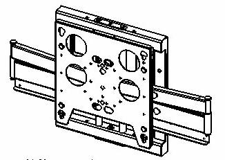
1 INSTALLATION INSTRUCTIONS Plasma Dual Swing-Out ( Series) Wall Mount The wall mount is a rugged, versatile, and installer-friendly solution to unique display mounting requirements. In addition to providing lateral movement, tilt and rotational capability, the allows you to mount your display landscape or portrait. The dual arm design provides the exceptional strength required to support heavy plasma screens (up to 61 ). You can pull your display out more than 33 from the wall, pivot it up to 90 degrees left or right of center, adjust the pitch infinitely between approximately 5 degrees up and 15 degrees down and allows some rotational adjustment. With the brackets attached to the display and the securely mounted on a wall, simply hang your plasma like a picture and lock the display in place using the convenient flag. Two outlet holes in the mounting plate and cable management along each arm are provided. BEFORE YOU BEGIN Caution: To prevent damage to the, which could affect or void the Factory warranty, and to the equipment that will be attached to it, thoroughly study all instructions and illustrations before you begin the installation. Pay particular attention to the Important Warnings and Precautions on Page 2. The maximum weight to be installed on the wall mount is 150 pounds (68.36 Kg). The wall mount is designed to be installed using wall studs or supporting framework. The wall to which the wall mount is anchored must be capable of supporting four times the total weight of the mount and all attached equipment. If you have any questions about this installation, contact Chief Manufacturing at CHIEF MANUFACTURING INC FAX EAGLE CREEK PARKWAY, STE. 700 SAVAGE, MINNESOTA USA PART NO (Rev. K) 2002 Chief Manufacturing
2 IMPORTANT WARNINGS AND PRECAUTIONS! WARNING: CAUTION: A WARNING alerts you to the possibility of serious injury or death if you do not follow the instructions. A CAUTION alerts you to the possibility of damage or destruction of equipment if you do not follow the corresponding instructions. WARNING: Improper installation can result in serious personal injury! Make sure that the structural members can support a redundant weight factor five times the total weight of the equipment: if not, reinforce the structure before installing the. WARNING: Be aware also of the potential for personal injury or damage to the unit if it is not adequately mounted. WARNING: The installer is responsible for verifying that the wall to which the is anchored will safely support the combined load of all attached components or other equipment. WARNING: The weight of the display placed on the must not exceed 150 lbs. (68.04 kg), the maximum load capacity of the. WARNING: Watch for pinch points. Do not put your fingers between movable parts. WARNING: Make sure the mount and brackets are correctly oriented. WARNING: Make sure the flag securing the display is completely lowered at all times except when removing or installing the display. CAUTION: Check the unit for shipping damage before you begin the installation. NOTE: Hardware for attaching this unit to the wall is not supplied. 2
3 TOOLS REQUIRED FOR INSTALLATION INSPECT THE UNIT BEFORE INSTALLING Electric drill and bit set Socket set with extension and open wrenches NOTE: Other tools may be required depending on the method of installing the lift in the ceiling. WARNING: Watch for pinch points. Do not put your fingers between movable parts. 1. Carefully inspect the for shipping damage. If any damage is apparent, call your carrier claims agent and do not continue with the installation until the carrier has reviewed the damage. NOTE: Read all instructions before starting installation. 2. Lay out components to ensure you have all the required parts before proceeding (see dimensional drawing on page 4). CONTENTS TOOLS REQUIRED FOR INSTALLATION... 3 INSPECT THE UNIT BEFORE INSTALLING... 3 DIMENSIONAL DRAWING... 4 INSTALLATION... 5 MOUNT THE DISPLAY... 6 CABLE MANAGEMENT... 6 ADJUSTMENTS... 7 REMOVE THE DISPLAY
4 DIMENSIONAL DRAWING 4

 and two cover plates (one each side. See Figure 1. 3. Drill two pilot holes 2 1/2 below the line drawn in Step 1 measuring 16 apart.")
5 INSTALLATION WARNING: WARNING: Install the as follows: The must be installed with correct end, indicated by Mount This Side Up, on top. It is the responsibility of the installer to verify that the wall to which the is anchored will safety support the combined load of all attached components and equipment. 1. Determine the exact mounting location prior to installation, considering the unit s total swing arm radius, and draw a level line to indicate the desired height of the top of the mounting plate. 2. Remove four screws (two each side) and two cover plates (one each side. See Figure Drill two pilot holes 2 1/2 below the line drawn in Step 1 measuring 16 apart. NOTE: Notice the wall plate has 2 nominal holes (2 X4 ) to accommodate two duplex wall outlets. WARNING: Improper installation can result in serious personal injury! Make sure that the structural members can support a redundant weight factor five times the total weight of the equipment: if not, reinforce the structure before installing the. 4. With the correctly oriented and level, secure the to the wall using two fasteners (not included) in the top mounting holes (see Figure 2). Fasteners must be driven into the supporting wall studs or other supporting framework. 5. Using the mounting plate as a template, drill pilot holes in the remaining four mounting holes and, if using one or both electrical box cutouts, trace cutout location(s). 6. Secure the to the wall using all six fasteners (not included). Fasteners must be driven into the supporting wall studs or other supporting framework. 7. Check mount to insure it is level and adjust to level if necessary. 8. Install two cover plates and secure using four screws (see Figure 1). Mounting Holes 16 Cover Plate Screws Figure 1. Cover Plate Removal Figure 2. Mounting Holes 5

.")
6 MOUNT THE DISPLAY 1. Make sure no power is supplied to the display and the locking device is in the unlocked (down) position (see Figure 3) before attempting to mount the display. NOTE: Skip step 2 for the Sony PFM Series plasmas. These models do not require a mounting bracket. 2. Following the instructions for mounting the hanging bracket of your specific plasma display panel, install the mounting bracket on your plasma display panel. WARNING: Watch for pinch points. Do not put your fingers between movable parts. 3. Using two people, slide the display down over the. Make sure the slots of the mounting bracket fully engage all hooks of the. 4. Secure the mounting bracket to the by completely engaging the locking device (see Figure 3). WARNING: Make sure the locking device securing the display is completely engaged at all times except when removing or installing the display. The locking device must be completely engaged during installation/removal of cables when the display is mounted. 5. Connect and secure power/audio/video cables, making sure to leave sufficient slack to allow for movement of the swing arms. Lock Unlock Figure 3. Locking Device CABLE MANAGEMENT WARNING: Make sure your cables do not run through a pinch point. 1. Route power/audio/video cables through the access hole (see Figure 4), allowing sufficient slack in cables for extension and avoiding pinch points. Tiewraps 2. Route power/audio/video cables along arm, using tiewraps to secure cables to arm, and through access hole. 3. Route power/audio/video cables through the cutout in the mounting plate, allowing sufficient slack in cables for extension. Cables Figure 4. Cord Management 6

, slightly tighten or loosen lateral tilt tension adjustment nut (see Figure 6). 2. Mount the display and check for desired tilt tension. 3. Repeat Steps 1 and 2 until desired tilt tension is obtained.")

7 ADJUSTMENTS Vertical Tilt Tension Adjustment 1. Using 5/32 Allen wrench (provided), slightly tighten or loosen two screws, one on each side, equally (see Figure 5). 2. With display mounted, check for desired vertical tilt tension. 3. Repeat Step 1 and Step 2 until desiredvertical tilt tension is obtained. Vertical Tilt Adj. Screw Lateral Tilt Tension Adjustment CAUTION: Overtightening lateral adjustment will cause excessive wear and may distort adjustment components. 1. Using a 3/8 wrench (not provided), slightly tighten or loosen lateral tilt tension adjustment nut (see Figure 6). 2. Mount the display and check for desired tilt tension. 3. Repeat Steps 1 and 2 until desired tilt tension is obtained. Rotational Tilt Tension Adjustment 1. If necessary, loosen or tighten bottom rotational tilt tension adjustment nut (see Figure 7). 2. Mount the display and check for desired rotational tilt tension. 3. Repeat Steps 1 and 2 until desired rotational tilt tension is obtained. Adjustment Nut Figure 5. Vertical Tilt Figure 6. Lateral Tilt Rotational Adj. Nut Figure 7. Rotational Adjustment 7

8 Swing Arm Location Adjustment 1. Remove the display from the mount. 2. Remove two screws securing retainer clip and remove retainer clip (see Figure 8). WARNING: The next step may release the arm assemblies from the mount. The arms and plate may fall if you are not careful. 3. Remove two bolts (one top and one bottom) securing retaining pin assemblies (one top and one bottom). WARNING: The next step will release the arm assemblies from the mount. The arms and plate may fall if you are not careful. 4. Remove two retaining pin assemblies. 5. Move arm assemblies to desired location. 6. Install retaining pin assemblies (one top and one bottom) and secure using two bolts (one top and one bottom). 7. Install retainer clip between swing arm assemblies and and secure retainer clip using two screws. Top Bolts Bottom Bolts Top Retaining Pin Assembly Retainer Clip Bottom Retaining Pin Assembly Figure 8. Swing Arm Adjustment REMOVE THE DISPLAY 1. Disconnect power/audio/video cables. 2. Release the locking device (see Figure 3). 3. Using two people, lift the display up from the. 8
Universal Pitch Adjustable Wall Mount For Flat Panel Display UPM-2401
 INSTALLATION INSTRUCTIONS Universal Pitch Adjustable Wall Mount For Flat Panel Display UPM-2401 Your new Chief Universal Pitch-Adjustable Wall Mount (UPM-2401) is a quick disconnect mounting system with
INSTALLATION INSTRUCTIONS Horizontal Array Pole Clamp Models: KTA-220/225 and KTA-320/325
 INSTALLATION INSTRUCTIONS Horizontal Array Pole Clamp Models: KTA-220/225 and KTA-320/325 The KTA-220/225 and KTA-320/325 pivot arrays allow horizontal (yaw), vertical (pitch), and roll display adjustment.
Universal Pitch-Adjustable Wall Mount For Flat Panel Display PLP-91/D
 INSTALLATION INSTRUCTIONS Universal Pitch-Adjustable Wall Mount For Flat Panel Display PLP-91/D Your new Wall Mount (PLP-91/D) is a quick disconnect mounting system with adjustability between 0 and 15
Plasma Gas Cylinder Lift
 I N S T R U C T I O N M A N U A L The Model PLM-42 is a smooth, quiet and reliable display lift mechanism, providing exceptional protection for your display unit in a mobile application. The lift is compatible
INSTALLATION INSTRUCTIONS Small Flat Panel Extreme Pitch Mechanism Model: FSA-1006
 INSTALLATION INSTRUCTIONS Small Flat Panel Extreme Pitch Mechanism Model: FSA-06 The FSA-06 Extreme Pitch Mechanism is an accessory kit for Small Flat Panel Display mounts. Specifications: fixed axis 90
GAS CYLINDER LIFTS BEFORE YOU BEGIN
 I N S T R U C T I O N M A N U A L GAS CYLINDER LIFTS The LM Series gas cylinder lifts are smooth, quiet reliable lift mechanisms for your valuable equipment in a mobile application. The LM Series can be
Plasma Display Electric Pop-Up Lift (PUL)
") I N S T R U C T I O N M A N U A L Plasma Display Electric Pop-Up Lift (PUL) Your is designed for installation in furniture or cabinets. Display mounting is made easy using the Q-latch mounting system and
I N S T R U C T I O N M A N U A L Plasma Display Electric Pop-Up Lift (PUL) Your is designed for installation in furniture or cabinets. Display mounting is made easy using the Q-latch mounting system and
Plasma Display Electric Ceiling Lifts
 I N S T R U C T I O N M A N U A L The Plasma Display Electric Ceiling Lift is designed for plasma displays requiring an extended drop (18 to 42 inches) from their hidden location. The lift is designed
PCS Series INSTALLATION INSTRUCTIONS. Single Ceiling Mount. Instrucciones de instalación Installationsanleitung Instruções de Instalação
 INSTALLATION INSTRUCTIONS Instrucciones de instalación Installationsanleitung Instruções de Instalação Istruzioni di installazione Installatie-instructies Instructions d installation Single Ceiling Mount
MCS Series INSTALLATION INSTRUCTIONS. Single Ceiling Mount. Instrucciones de instalación Installationsanleitung Instruções de Instalação
 INSTALLATION INSTRUCTIONS Instrucciones de instalación Installationsanleitung Instruções de Instalação Istruzioni di installazione Installatie-instructies Instructions d installation Single Ceiling Mount
PFW 6855 Installation Guide Installationsanleitung, Guía de Instalacíon, Guida de Installazione, Guide d Installation, Installatie gids
 Installation Guide Installationsanleitung, Guía de Instalacíon, Guida de Installazione, Guide d Installation, Installatie gids Max: 227kg/500lbs MOUIN_PFW6855_V01 Refer to Step: Included components 3 10
Installation Manual for Philips SureSigns VS3/VS4/VM4/VM6/VM8/VSV VHM-25 Countertop Mount
 3875 Cypress Drive Petaluma, CA 94954 800.228.2555 707.773.1100 Fax 707.773.1180 www.gcx.com Installation Manual for Philips SureSigns VS3/VS4/VM4/VM6/VM8/VSV VHM-25 Countertop Mount Install Time: 20-30
MCS Series INSTALLATION INSTRUCTIONS. Single Medium Ceiling Mount
 INSTALLATION INSTRUCTIONS Single Medium Ceiling Mount Spanish Product Description German Product Description Portuguese Product Description Italian Product Description Dutch Product Description French
VHM-P (Non-Locking) and VHM-PL (Locking) Variable Height Arm with Slide-In Mounting Plate
 and VHM-PL (Locking) Variable Height Arm with Slide-In Mounting Plate") 3875 Cypress Drive Petaluma, CA 94954 800.228.2555 +1.707.773.1100 Fax 707.773.1180 www.gcx.com VHM-P (Non-Locking) and VHM-PL (Locking) Variable Height Arm with Slide-In Mounting Plate (Refer to qualified
3875 Cypress Drive Petaluma, CA 94954 800.228.2555 +1.707.773.1100 Fax 707.773.1180 www.gcx.com VHM-P (Non-Locking) and VHM-PL (Locking) Variable Height Arm with Slide-In Mounting Plate (Refer to qualified
FRONT STABILIZER BAR KIT
 FRONT STABILIZER BAR KIT P/N 2881205 APPLICATION RZR XP 1000 MY16 and Newer, RZR XP 4 1000 MY16 and Newer BEFORE YOU BEGIN Read these instructions and check to be sure all parts and tools are accounted
(Refer to qualified personnel)
") 3875 Cypress Drive Petaluma, CA 94954 800.228.2555 +1.707.773.1100 Fax 707.773.1180 www.gcx.com Installation Guide VHM-P (Non-Locking) and VHM-PL (Locking) Variable Height Arm (Slide-Above-Arm Configuration)
3875 Cypress Drive Petaluma, CA 94954 800.228.2555 +1.707.773.1100 Fax 707.773.1180 www.gcx.com Installation Guide VHM-P (Non-Locking) and VHM-PL (Locking) Variable Height Arm (Slide-Above-Arm Configuration)
SAFETY THIS PRODUCT IS FOR OFFROAD USE ONLY. ALL LIABILITY FOR INSTALLATION AND USE RESTS WITH THE OWNER.
 SAFETY Your safety and the safety of others is very important. In order to help you make informed decisions about safety, we have provided installation instructions and other information. These instructions
3875 Cypress Drive Petaluma, CA Fax
 3875 Cypress Drive Petaluma, CA 94954 800.228.2555 +1.707.773.1100 Fax 707.773.1180 www.gcx.com VHM-P (Non-Locking) Variable Height Arm with Fixed Angle Front End for Flat Panel / Keyboard Bracket (L Brackets
SAFETY THIS PRODUCT IS FOR OFFROAD USE ONLY. ALL LIABILITY FOR INSTALLATION AND USE RESTS WITH THE OWNER.
 SAFETY Your safety and the safety of others is very important. In order to help you make informed decisions about safety, we have provided installation instructions and other information. These instructions
VHM-P (Non-Locking) Variable Height Arm with VESA Mounting Plate for 75 x 75mm or 100 x 100mm applications
 Variable Height Arm with VESA Mounting Plate for 75 x 75mm or 100 x 100mm applications") 3875 Cypress Drive Petaluma, CA 94954 800.228.2555 +1.707.773.1100 Fax 707.773.1180 www.gcx.com VHM-P (Non-Locking) Variable Height Arm with VESA Mounting Plate for 75 x 75mm or 100 x 100mm applications
3875 Cypress Drive Petaluma, CA 94954 800.228.2555 +1.707.773.1100 Fax 707.773.1180 www.gcx.com VHM-P (Non-Locking) Variable Height Arm with VESA Mounting Plate for 75 x 75mm or 100 x 100mm applications
NOVO LIGHTED MIRROR. Installation Instructions
 NOVO LIGHTED MIRROR Installation Instructions IMPORTANT SAFETY INSTRUCTIONS Must be installed by a qualified technician. Read these installation instructions. Keep these instructions for future use. Follow
SAFETY THIS PRODUCT IS FOR OFFROAD USE ONLY. ALL LIABILITY FOR INSTALLATION AND USE RESTS WITH THE OWNER.
 SAFETY Your safety and the safety of others is very important. In order to help you make informed decisions about safety, we have provided installation instructions and other information. These instructions
INSTALLATION INSTRUCTIONS
 INSTALLATION INSTRUCTIONS AUTOMOTIVE PRODUCTS, INC. APPLICATION: 2006-2008 FORD F-150 PART NUMBER: 45-92010, 40-92015 WINCH MOUNTED SPORTSMAN GRILLE GUARD ITEM QUANTITY ITEM DESCRIPTION TOOLS NEEDED 1
<THESE INSTRUCTIONS MUST BE GIVEN TO THE END USER> B&W Trailer Hitches 1216 Hawaii Road / PO Box 186 Humboldt, KS P: F:
 B&W Trailer Hitches 26 Hawaii Road / PO Box 86 Humboldt, KS 6678 P:620.73.366 F:620.869.903 RAM OEM Mount System Installation Instructions 25,000 LBS.
SAFETY THIS PRODUCT IS FOR OFFROAD USE ONLY. ALL LIABILITY FOR INSTALLATION AND USE RESTS WITH THE OWNER.
 Installation Instructions SAFETY Your safety and the safety of others is very important. In order to help you make informed decisions about safety, we have provided installation instructions and other
Installation Manual for VHM-25 Series Arms Channel Mount
 3875 Cypress Drive Petaluma, CA 94954 800.228.2555 707.773.1100 Fax 707.773.1180 www.gcx.com Installation Manual for VHM25 Series Arms Channel Mount Install Time: 1015 minutes The purpose of this manual
SAFETY THIS PRODUCT IS FOR OFFROAD USE ONLY. ALL LIABILITY FOR INSTALLATION AND USE RESTS WITH THE OWNER.
 SAFETY Your safety and the safety of others is very important. In order to help you make informed decisions about safety, we have provided installation instructions and other information. These instructions
CMA347 INSTALLATION INSTRUCTIONS. Vibration Damper Mount
 INSTALLATION INSTRUCTIONS Vibration Damper Mount Spanish Product Description German Product Description Portuguese Product Description Italian Product Description Dutch Product Description French Product
SAFETY THIS PRODUCT IS FOR OFFROAD USE ONLY. ALL LIABILITY FOR INSTALLATION AND USE RESTS WITH THE OWNER.
 SAFETY Your safety and the safety of others is very important. In order to help you make informed decisions about safety, we have provided installation instructions and other information. These instructions
RMK HANDLEBAR KIT P/N ; ; APPLICATION BEFORE YOU BEGIN KIT CONTENTS. Verify accessory fitment at Polaris.com.
 RMK HANDLEBAR KIT P/N 2883835; 2883836; 2883837 APPLICATION Verify accessory fitment at Polaris.com. BEFORE YOU BEGIN Read these instructions and check to be sure all parts and tools are accounted for.
Installation Instructions Table of Contents
 Installation Instructions Table of Contents Pre- Installation of Garage Storage Lift 2 Layout the Garage Storage Lift 3 Installing the strut Channels 3 Install the Drive Assembly 5 Install the Drive Shaft
CMA360 INSTALLATION INSTRUCTIONS. I-Beam Clamp Accessory. Instrucciones de instalación Installationsanleitung Instruções de Instalação
 INSTALLATION INSTRUCTIONS Instrucciones de instalación Installationsanleitung Instruções de Instalação Istruzioni di installazione Installatie-instructies Instructions d installation I-Beam Clamp Accessory
FOR SIT-STAND WORKSTATION
 INSTALLATION MANUAL FOR SIT-STAND WORKSTATION Weight Capacity: 6.5-24.5 lbs. 6017180 Rev. B Contents Tools Required / Supplied Part Kits / Warnings/Disclaimers...2 Base Installation Clamp Mount Base Location...3
SAFETY SENSORS FIELD OF VIEW WILL BE ALTERED WITH USE OF THE REPLACEMENT BUMPER. Injury hazard
 SAFETY Your safety and the safety of others is very important. In order to help you make informed decisions about safety, we have provided installation instructions and other information. These instructions
Down and Out Motor Mount Assembly & Installation Directions
 Down and Out Motor Mount Assembly & Installation Directions Mounting the Down and Out Motor Mount correctly takes a lot of thought and a lot of planning. Please read the directions thoroughly and plan
SAFETY THIS PRODUCT IS FOR OFFROAD USE ONLY. ALL LIABILITY FOR INSTALLATION AND USE RESTS WITH THE OWNER.
 SAFETY Your safety and the safety of others is very important. In order to help you make informed decisions about safety, we have provided installation instructions and other information. These instructions
INSTALLATION INSTRUCTIONS
 INSTALLATION INSTRUCTIONS Universal Short Throw Projector Wall Mount Model: NORTH AMERICA 3130 East Miraloma Avenue Anaheim, CA 92806 USA USA and Canada Phone: 1-800-368-9700 Fax: 1-800-832-4888 Other
SAFETY THIS PRODUCT IS FOR OFFROAD USE ONLY. ALL LIABILITY FOR INSTALLATION AND USE RESTS WITH THE OWNER.
 SAFETY Your safety and the safety of others is very important. In order to help you make informed decisions about safety, we have provided installation instructions and other information. These instructions
RETRACTABLE CEILING COLUMN
 RETRACTABLE CEILING COLUMN Installation Manual RETRACTABLE CEILING COLUMN INTRODUCTION Location, sequence of services and orientation of Surgical Ceiling Columns are specified on the building plans. Be
Installation Guide VHM Wall Mount Kit for Philips MX600/700/800 and MP60/70 IntelliVue
 Installation Guide VHM Wall Mount Kit for Philips MX600/700/800 and MP60/70 IntelliVue The purpose of this guide is to: 1. Describe attachment of Table Top Mount to Mounting Adapter (page 2). 2. Describe
SAFETY THIS PRODUCT IS FOR OFFROAD USE ONLY. ALL LIABILITY FOR INSTALLATION AND USE RESTS WITH THE OWNER.
 SAFETY Your safety and the safety of others is very important. In order to help you make informed decisions about safety, we have provided installation instructions and other information. These instructions
SAFETY SENSORS FIELD OF VIEW WILL BE ALTERED WITH USE OF THE REPLACEMENT BUMPER. Injury hazard
 SAFETY Your safety and the safety of others is very important. In order to help you make informed decisions about safety, we have provided installation instructions and other information. These instructions
INSTALLATION INSTRUCTIONS
 AUTOMOTIVE PRODUCTS, INSTALLATION INSTRUCTIONS ULTIMATE BULL BAR APPLICATION: 2009-2018 Dodge Ram 1500 (Excl. Rebel Model) 2019 Dodge Ram 1500 Classic PART NUMBER: 32-1960, 32-1965, 32-1960L, 32-1965L
INSTALLATION INSTRUCTIONS
 AUTOMOTIVE PRODUCTS, INSTALLATION INSTRUCTIONS HDX DROP STEP APPLICATION: 2007-2017 Chevy Silverado / GM Sierra / 1500-2500-3500 Ext. / Double / Crew Cab PART NUMBER: 56-13715, 56-13725 ITEM QUANTITY DESCRIPTION
FOR WALL MOUNT COMBINATION ARMS
 INSTALLATION MANUAL FOR WALL MOUNT COMBINATION ARMS LIGHT DUTY ARMS HEAVY DUTY ARMS KEYBOARD TRAY VERSION Weight Capacity 4-20 lbs KEYBOARD TRAY VERSION Weight Capacity 8-40 lbs WORKSTATION VERSION Weight
Procedure Replacing a Cover
 Procedure 7.1 - Replacing a Cover Cover Removal 1. Remove two screws, one each side, from the front of the top cover. Remove the top cover. See Diagram 7.1. Diagram 7.1 - RBK 815 Covers Top Cover Left
INSTALLATION INSTRUCTIONS WARN FRONT RECEIVER For: DODGE RAM, 2500 and 3500, + 03 Kit Number: 65370
 INSTALLATION INSTRUCTIONS WARN FRONT RECEIVER For: DODGE RAM, 2500 and 3500, + 03 Kit Number: 65370 USE EXTREME CAUTION WHEN DRILLING ON ANY VEHICLE. MAKE SURE THAT ALL FUEL LINES, BRAKE LINES, ELECTRICAL
TIP-OUT GLASS WINDSHIELD KIT
 TIP-OUT GLASS WINDSHIELD KIT P/N 2881108 APPLICATION Verify accessory fitment at Polaris.com. BEFORE YOU BEGIN Read these instructions and check to be sure all parts and tools are accounted for. Please
SAFETY. Read and understand all safety precautions and instructions before installing this product.
 SAFETY Your safety and the safety of others is very important. In order to help you make informed decisions about safety, we have provided installation instructions and other information. These instructions
SAFETY THIS PRODUCT IS FOR OFFROAD USE ONLY. ALL LIABILITY FOR INSTALLATION AND USE RESTS WITH THE OWNER.
 SAFETY Your safety and the safety of others is very important. In order to help you make informed decisions about safety, we have provided installation instructions and other information. These instructions
Part Name/Description Part Number Quantity Instruction Kit Metalfor Flow Sensor
 NOTE: Indented items indicate parts included in an assembly listed above Part Name/Description Part Number Quantity Instruction Kit Metalfor 4101091 1 Flow Sensor 4001356 1 Deflector plate 2000612-1 1
SAFETY. Read and understand all safety precautions and instructions before installing this product.
 SAFETY Your safety and the safety of others is very important. In order to help you make informed decisions about safety, we have provided installation instructions and other information. These instructions
INSTALLATION INSTRUCTIONS
 INSTALLATION INSTRUCTIONS OUTLAW REAR BUMPER APPLICATION: 2016-2018 Chevrolet Silverado 1500 PART NUMBER: 58-81005 CONTENT ITEM QUANTITY DESCRIPTION TOOLS NEEDED 1 1 REAR BUMPER 18MM WRENCH 2 4 SENSOR
Assist Step Kit Installation (Side Assist Step)
") Page 1 of 6 2015 Chevrolet Silverado - 2WD Cheyenne, Sierra, Silverado Accessory Installation Manual Accessories Exterior Trim Accessories Accessories Document ID: 2741491 Assist Step Kit Installation
Page 1 of 6 2015 Chevrolet Silverado - 2WD Cheyenne, Sierra, Silverado Accessory Installation Manual Accessories Exterior Trim Accessories Accessories Document ID: 2741491 Assist Step Kit Installation
SAFETY THIS PRODUCT IS FOR OFFROAD USE ONLY. ALL LIABILITY FOR INSTALLATION AND USE RESTS WITH THE OWNER.
 SAFETY Your safety and the safety of others is very important. In order to help you make informed decisions about safety, we have provided installation instructions and other information. These instructions
GE CARESCAPE Monitor B650 on VHM- PL Variable Height Arm Channel Mount with Vertical Position Lock
 GE CARESCAPE Monitor B650 on VHM- PL Variable Height Arm Channel Mount with Vertical Position Lock PRODUCT DETAILS VHM-PL (Locking) Variable Height Arm with 14" / 35.6 cm Extension and Slide-In Mounting
INSTALLATION INSTRUCTIONS
 AUTOMOTIVE PRODUCTS, INC. INSTALLATION INSTRUCTIONS ULTIMATE BULL BAR APPLICATION: 2017 Ford F-250/350 PART NUMBER: 32-3900, 32-3905, 32-3900L, 32-3905L ITEM QUANTITY DESCRIPTION TOOLS NEEDED 1 1 ULTIMATE
SAFETY. Injury hazard
 SAFETY Your safety and the safety of others is very important. In order to help you make informed decisions about safety, we have provided installation instructions and other information. These instructions
SERVICE MANUAL SL220-SK6. Lift Assembly Replacement
 SERVICE MANUAL Lift Assembly Replacement Spanish Product Description German Product Description Portuguese Product Description Italian Product Description Dutch Product Description French Product Description
Installation Guide. Philips MP20/30/40/50 IntelliVue VHM Wall Mount Kit
 Installation Guide Philips MP20/30/40/50 IntelliVue VHM Wall Mount Kit The purpose of this guide is to: 1. Describe attachment of Table Top Mount to Mounting Adapter. 2. Describe attachment of Mounting
SAFETY THIS PRODUCT IS FOR OFFROAD USE ONLY. ALL LIABILITY FOR INSTALLATION AND USE RESTS WITH THE OWNER.
 SAFETY Your safety and the safety of others is very important. In order to help you make informed decisions about safety, we have provided installation instructions and other information. These instructions
INSTALLATION MANUAL FOR PILOT WORKSTATION
 INSTALLATION MANUAL FOR PILOT WORKSTATION Weight Capacity: 5-25 lbs. Monitor Weight: 5-20 lbs. 6011180 Rev. B Contents Tools Required / Supplied Part Kits / Warnings/Disclaimer...2 Possible Base Mounting
SAFETY THIS PRODUCT IS FOR OFFROAD USE ONLY. ALL LIABILITY FOR INSTALLATION AND USE RESTS WITH THE OWNER.
 SAFETY Your safety and the safety of others is very important. In order to help you make informed decisions about safety, we have provided installation instructions and other information. These instructions
AMAYA XT/BRAVO X-Cable Tension Gauge User Instructions
 AMAYA XT/BRAVO X-Cable Tension Gauge User Instructions The following instructions will guide you through checking and, if necessary, adjusting the X-Cable tension on your AMAYA XT or BRAVO machine. The
SAFETY. Read and understand all safety precautions and instructions before installing this product.
 SAFETY Your safety and the safety of others is very important. In order to help you make informed decisions about safety, we have provided installation instructions and other information. These instructions
<THESE INSTRUCTIONS MUST BE GIVEN TO THE END USER> B&W
 B&W Trailer Hitches 26 Hawaii Road / PO Box 86 Humboldt, KS 6678 P:620.73.366 F:620.869.903 GM Puck Mount System Installation Instructions 20,000 LBS.
INTEGRATED1500LB WINCH KIT
 INTEGRATED1500LB WINCH KIT P/N 2882798 APPLICATION Verify accessory fitment at Polaris.com. BEFORE YOU BEGIN Read these instructions and check to be sure all parts and tools are accounted for. Please retain
SAFETY. Read and understand all safety precautions and instructions before installing this product.
 SAFETY Your safety and the safety of others is very important. In order to help you make informed decisions about safety, we have provided installation instructions and other information. These instructions
CAUTION. INSTALLATION INSTRUCTIONS Part Number Hidden Winch Kit with special XD 9000 Short Drum Winch For Ford F-150 Truck
 INSTALLATION INSTRUCTIONS Part Number 69110 Hidden Winch Kit with special XD 9000 Short Drum Winch For Ford F-150 Truck As you read these instructions, you will see NOTES, CAUTIONS and WARNINGS. Each message
INSTALLATION INSTRUCTIONS
 AUTOMOTIVE PRODUCTS, INSTALLATION INSTRUCTIONS HDX DROP STEP APPLICATION: 2007-2016 Chevy Silverado / GM Sierra / 1500-2500-3500 PART NUMBER: 56-13715, 56-13725 CONTENT ITEM QUANTITY DESCRIPTION TOOLS
SAFETY SENSORS FIELD OF VIEW WILL BE ALTERED WITH USE OF THE REPLACEMENT BUMPER. Injury hazard
 SAFETY Your safety and the safety of others is very important. In order to help you make informed decisions about safety, we have provided installation instructions and other information. These instructions
SAFETY THIS PRODUCT IS FOR OFFROAD USE ONLY. ALL LIABILITY FOR INSTALLATION AND USE RESTS WITH THE OWNER.
 SAFETY Your safety and the safety of others is very important. In order to help you make informed decisions about safety, we have provided installation instructions and other information. These instructions
Installation Guide VHM Arm Kit for Philips Heartstart MRx and Heartstart XL+
 Installation Guide VHM Arm Kit for Philips Heartstart MRx and Heartstart XL+ The purpose of this guide is to: 1. Describe installation of Arm in channel (page 2). 2. Describe mounting of defibrillator
2015 Mustang Lightbar (All Models) CDC#
 CDC#") 2015 Mustang Lightbar (All Models) CDC# 1511-7000-01 Components: 1 CDC Lightbar Note: READ instructions before starting installation!!! CDC Part# Driver side bracket 0511-6001-05 Passenger side bracket
2015 Mustang Lightbar (All Models) CDC# 1511-7000-01 Components: 1 CDC Lightbar Note: READ instructions before starting installation!!! CDC Part# Driver side bracket 0511-6001-05 Passenger side bracket
E Series Enclosures Installation Instructions (UL /UL2416 E Series Equipment Cabinet/Rack)
") E Series Enclosures Installation Instructions (UL60950-1/UL2416 E Series Equipment Cabinet/Rack) WeRackYourWorld.com 1-866-TRY-GLCC (879-4522) Instructions for the following Great Lakes Enclosures: GL720E-2432,
E Series Enclosures Installation Instructions (UL60950-1/UL2416 E Series Equipment Cabinet/Rack) WeRackYourWorld.com 1-866-TRY-GLCC (879-4522) Instructions for the following Great Lakes Enclosures: GL720E-2432,
<THESE INSTRUCTIONS MUST BE GIVEN TO THE END USER> B&W Trailer Hitches 1216 Hawaii Road / PO Box 186 Humboldt, KS P: F:
 B&W Trailer Hitches 26 Hawaii Road / PO Box 86 Humboldt, KS 6678 P:620.73.366 F:620.869.903 Ford OEM Mount System Installation Instructions 20,000 LBS.
SAFETY THIS PRODUCT IS FOR OFFROAD USE ONLY. ALL LIABILITY FOR INSTALLATION AND USE RESTS WITH THE OWNER.
 SAFETY Your safety and the safety of others is very important. In order to help you make informed decisions about safety, we have provided installation instructions and other information. These instructions
SAFETY. Read and understand all safety precautions and instructions before installing this product.
 SAFETY Your safety and the safety of others is very important. In order to help you make informed decisions about safety, we have provided installation instructions and other information. These instructions
R O A D M A S T E R, I N C.
 R O A D M A S T E R, I N C. MOUNTING BRACKET KIT Item Qty. Length Width Description Part # 1... 2... 1 1/2"... 1/2"...BOLT...350095-00 2... 2... 5"... 1/2"...BOLT...350107-00 3... 2... 3"... 1/2"...BOLT...350101-00
PAC-710 INSTALLATION INSTRUCTIONS. Shelf Accessory
 INSTALLATION INSTRUCTIONS Shelf Accessory Spanish Product Description German Product Description Portuguese Product Description Italian Product Description Dutch Product Description French Product Description
SAFETY. Read and understand all safety precautions and instructions before installing this product.
 SAFETY Your safety and the safety of others is very important. In order to help you make informed decisions about safety, we have provided installation instructions and other information. These instructions
SAFETY THIS PRODUCT IS FOR OFFROAD USE ONLY. ALL LIABILITY FOR INSTALLATION AND USE RESTS WITH THE OWNER.
 SAFETY Your safety and the safety of others is very important. In order to help you make informed decisions about safety, we have provided installation instructions and other information. These instructions
1-3/8 Designer Metals Telescoping Traversing Rod Installation Instructions
 1-3/8 Designer Metals Telescoping Traversing Rod Installation Instructions Please read and follow all installation instructions provided for proper operation and enjoyment of your new drapery hardware
Model 3770 WARNING. Failure to comply with the safety information in these instructions could result in serious injury or death.
 B&W Trailer Hitches 1216 Hawaii Road / PO Box 186 Humboldt, KS 66748 P:620.473.3664 See Limited Lifetime Warranty at F:620.869.9031 bwtrailerhitches.com/warranty NOTE: We recommend reading instructions
SAFETY THIS PRODUCT IS FOR OFFROAD USE ONLY. ALL LIABILITY FOR INSTALLATION AND USE RESTS WITH THE OWNER.
 SAFETY Your safety and the safety of others is very important. In order to help you make informed decisions about safety, we have provided installation instructions and other information. These instructions
TV Lift System Model L-75i Installation Instructions
 TV Lift System Model L-75i Installation Instructions Below is a parts list describing all of the items included with the Model L-75i Lift System. Contact: Support@Nexus21.com Toll Free: (866) 500-5438
Please read BOTH these Installation Instructions and the General Information sheet prior to installing or operating this equipment.
 Attachment Tab Height: 24-1/4 Serial Number Attachment Tab Width: 24 Please read BOTH these and the General Information sheet prior to installing or operating this equipment. 1. Blue Ox towing products
CONTENTS: 5740AH - 40 Ton Air/Hydraulic Shop Press 5750AH - 50 Ton Air/Hydraulic Shop Press OWNER'S MANUAL
 OWNER'S MANUAL CONTENTS: Page 1 Specifications 2 Safety Information and Warranty Information 3 Parts List 4-6 Assembly Instructions 7 Pump and Ram Assembly Instructions 8 Procedure for Bleeding Air 9 Pump
SAFETY THIS PRODUCT IS FOR OFFROAD USE ONLY. ALL LIABILITY FOR INSTALLATION AND USE RESTS WITH THE OWNER.
 SAFETY Your safety and the safety of others is very important. In order to help you make informed decisions about safety, we have provided installation instructions and other information. These instructions
INSTALLATION INSTRUCTIONS ATV WINCH MULTI-MOUNT Multi-Mount Mounting-Kit: PN Application: YAMAHA GRIZZLY 660
 INSTALLATION INSTRUCTIONS ATV WINCH MULTI-MOUNT Multi-Mount Mounting-Kit: PN 63172 Application: YAMAHA GRIZZLY 660 As you read these instructions, you will see NOTES, CAUTIONS and WARNINGS. Each message
Installation Guide Philips MP2 IntelliVue M-Series Arm (12'' or 8'') Rail Mount Kit
 Rail Mount Kit") Installation Guide Philips MP2 IntelliVue M-Series Arm (12'' or 8'') Rail Mount Kit The purpose of this guide is to: 1. Describe mounting of MP2 equipment on Mounting Bracket (page 2). 2. Describe mounting
Installation Guide Philips MP2 IntelliVue M-Series Arm (12'' or 8'') Rail Mount Kit The purpose of this guide is to: 1. Describe mounting of MP2 equipment on Mounting Bracket (page 2). 2. Describe mounting
B&W Trailer Hitches 1216 Hawaii Road / PO Box 186 Humboldt, KS P: F:
 B&W Trailer Hitches 1216 Hawaii Road / PO Box 186 Humboldt, KS 66748 P:620.473.3664 F:620.869.9031 NOTE: We recommend reading instructions before beginning the installation. Ford OEM Mount System Slider
LoD Offroad. Jeep JK Door Linked Rear Bumper with Tire Carrier Installation Instructions
 LoD Offroad Jeep JK Door Linked Rear Bumper with Tire Carrier Installation Instructions Please read through the instructions before beginning any part of the installation process. Packaging List: 1-Rear
PFadvantage JD 3300/4400/6600/7700; 4420
 Ag Leader Technology Combine Installation JD 33//66/77; 2 Note: Indented items indicate parts included Quantity by Model in an assembly listed above Early Late Part Name/Description Part Number 3 3 6 6