TV Lift System Model L-75i Installation Instructions
|
|
|
- Sara Cole
- 5 years ago
- Views:
Transcription


1 TV Lift System Model L-75i Installation Instructions

 500-5438 Phone: (480)")


 Bayonet Sleeves (2) (6 1/8 x 3 ¼ )")
 Bayonet Bracket (4 ¾ x 5 ¼ ) Center")
 Screen Back Plate (36 x 7 ¾ )")
2 Below is a parts list describing all of the items included with the Model L-75i Lift System. Contact: Support@Nexus21.com Toll Free: (866) Phone: (480) Fax: (480) Revised: 03/02/17 Before beginning assembly and installation, please make sure that you have all items included on the list. If any parts are missing or damaged, please contact Nexus 21. Our contact information is shown at the top of this page. Parts List Lift Columns (3) (Marked A, B, and C) (22 x 4 ) Bayonet Sleeves (2) (6 1/8 x 3 ¼ ) Screen Support Bracket (6 ¼ x 17 ½ ) Lid Plate (7 ½ x 30 ) Bayonet Bracket (4 ¾ x 5 ¼ ) Center Riser Bracket (20 ¾ x 18 ¼ x 5 ) Rear Support Bracket (24 x 3 ) Screen Back Plate (36 x 7 ¾ ) Front Cover (21 ¾ x 20 x 2 ¾ ) Lower Cable Track Bracket (2 ¾ x 3 ¾ ) Upper Cable Track Bracket (3 1/8 x 2 3/8 ) Center Cable Track Bracket (7 ½ x 30 ) Parts list continued 1
 Assorted Hardware Pack Cables & Other Parts o Motor Cables (3) Black cable with white, six-pin plugs.")
 Use to connect the RF Receiver to the Control Box.")
 Cable Ties you will use these with the Snakeskin Wrap to help keep your wires in order.")
 -- 6mm x 12mm BHMS o Two (2) 6mm x 16mm BHMS with Two (2) ¼ Washers o Twelve (12) -- 6mm x 20mm BHMS o Four (4) --")
 5mm x 12mm FHMS o Four (4) -- Square Multi-Mount Washers o Two (2) -- Screen Locks o Four (4) -- Allen Wrenches 3mm, 4mm, 3/16 and 7/32 Contents of hardware pack that is labeled LID")
3 Parts List, continued Control Box (10 ½ x 3 ¾ x 1 ½ ) Lid Support Brackets (2) (14 x 2 ¾ ) Cable Tracks (2) (Short Upper, Long Lower) Vertical Mounting Bars (2) (7 ½ x 30 ) Top Beam Support (22 x 5 5/8 ) Assorted Hardware Pack Cables & Other Parts o Motor Cables (3) Black cable with white, six-pin plugs. Use these cables to connect the Lift Columns to the Control Box (using slots #1, #2, and #3 on the Control Box). There are 3 Cables total, in 2 different sizes, two 2m and one 2.5m. o Power Cable Connects Control Box to power outlet. Three feet long. o RF Cable (only present if you ordered the RF version of the Lift System) Use to connect the RF Receiver to the Control Box. Ends have RJ-45 connectors. One foot long. o Snakeskin Cable Management Wrap this is a 48 length of black cable wrap material. You may or may not use Snakeskin depending on your install preferences. o Ten (10) Cable Ties you will use these with the Snakeskin Wrap to help keep your wires in order. o Extension Pak This will give you 7 of additional cable to extend your back up switch to closer location. Contents of hardware pack that is labeled L-75i HARDWARE o Seventeen (17) -- 6mm x 12mm BHMS o Two (2) 6mm x 16mm BHMS with Two (2) ¼ Washers o Twelve (12) -- 6mm x 20mm BHMS o Four (4) -- 3/8-16 x ¾ BHMS o Four (4) -- #8 x ¾ FHWS o Two (2) -- #10 x 1 ¾ FHWS o Eight (8) -- #10 x ¾ THWS o Four (4) -- 6mm x 12mm FHMS o Twelve (12) -- 6mm x 20mm FHMS o Eight (8) -- 6mm x 40mm FHMS o Eight (8) 5mm x 12mm FHMS o Four (4) -- Square Multi-Mount Washers o Two (2) -- Screen Locks o Four (4) -- Allen Wrenches 3mm, 4mm, 3/16 and 7/32 Contents of hardware pack that is labeled LID STABILIZATION PACK o Four (4) Shoulder Bolts o Four (4) -- Lid Stabilization Springs o Four (4) -- Brass Threaded Inserts o Eight (8) ½ Nylon Spacers END OF PARTS LIST


4 SAFETY INFORMATION SEVERE PERSONAL INJURY AND PROPERTY DAMAGE CAN RESULT FROM IMPROPER INSTALLATION OR ASSEMBLY. READ THE FOLLOWING WARNINGS BEFORE BEGINNING: TV HAZARD LID HAZARD CAUTION: Avoid contact with the TV and Lift System during operation. Use with caution. CAUTION: The lid of your enclosure must be installed as described in the instructions, using the Steel Threaded Tapered Pins. Installing the enclosure lid in any other fashion will create hazardous pinch points that can cause serious personal injury. WARNINGS: 1. Do not use this product for any application other than those specified by Nexus Do not exceed the weight capacity. This can result in serious personal injury or damage to the equipment. It is the installer s responsibility to ensure that the total combined weight of all attached components does not exceed that of the maximum figure stated. 3. Follow all technical specifications and instructions during the installation. 4. Only use attachments/accessories specified by the manufacturer. 5. Close supervision is necessary when this system is being used by, or near, children, or disabled persons. 6. It is the responsibility of the installer to warn all potential users of the dangers of interfering with the mechanism during operation. 7. Read all technical instructions fully before installation and use. It is the installer s responsibility to ensure that all documentation is passed on the users and read fully before operation. 8. Failure to provide adequate structural strengthening, prior to installation can result in serious personal injury or damage to the equipment. It is the installer s responsibility to ensure the structure to which the Lift System is affixed can support four times the weight of the system. 9. Risk of electric shock. Do not attempt to open the Control Box. 10. To reduce risk of fire or electric shock, do not expose parts to rain or other liquids. 11. Protect the power cord from being walked on or pinched. 12. Keep all documentation. 13. Heed all warnings. 14. Clean only with a dry cloth. 15. Refer all service questions to Nexus 21 if the system does not operate normally. Nexus 21 disclaims any liability for modifications, improper installations, or installations over the specified weight range. Nexus 21 will not be liable for any damages arising out of the use of, or inability to use, Nexus 21 products. Nexus 21 bears no responsibility for incidental or consequential damages. This includes, but is not limited to, any labor charges for the servicing of Nexus 21 products performed by anyone other than Nexus 21. Nexus 21 intends to make this and all documentation as accurate as possible. However, Nexus 21 makes no claim that the information contained herein covers all details, conditions or variations, nor does it provide for every possible contingency in connection with the installation or use of this product. The information contained in this document is subject to change without prior notice or obligation of any kind. Nexus 21 makes no representation of warranty, expressed or implied, regarding the information contained herein. Nexus 21 assumes no responsibility for accuracy, completeness or sufficiency of the information contained in this document. 3
.")

 the most common form of control is to WIRE IT DIRECTLY to the relays of")

5 Types of Controls for Nexus 21 Lift Systems All Nexus 21 Lift Systems come standard with a wireless remote control and receiver. We offer a choice of two different types of remotes: IR and RF (both of which are explained in detail below). Our standard control type is RF, so unless you specifically requested the IR version when you made your purchase, you probably received the RF controls with this Lift System. The method of installation for each type of remote control is slightly different, so you should now identify which type of remote you have by reading below, and then follow the instructions for that type of remote. NOTE: If you will be using the Lift with a home control system (like the ones made by companies such as Crestron or Control 4) the most common form of control is to WIRE IT DIRECTLY to the relays of your home control system. This direct-wire method is called Integration by Contact Closure, and is accomplished by using the Contact Closure Hardware that is supplied with the IR Control Kit to connect the Lift to your home control system. Before You Begin the Installation: Identify Your Control Type IR (Infrared) This control option allows you to utilize a 3 rd party universal style remote control to raise and lower the TV Lift. Your universal remote will learn the IR codes from the provided IR Handset, which will enable you to control the lift. The universal remote will then communicate with the eye located on the IR Receiver via your 3 rd party emitter (or flasher). Instructions for setting the TV Lift s travel limit are on Page 26. NOTE: If you are NOT planning on using a 3 rd party Universal Remote, switch to the RF setup. (There is no charge for swapping) These are the parts included with IR controls: Contact Closure Hardware IR Receiver IR Handset Height Limit Insert RF (Radio Frequency) - This system utilizes a wireless remote control handset that sends a radio signal to the RF Receiver. The radio signal can go through cabinet walls and does not require line-of-sight. Instructions for setting the Lift System travel limit are on Page 26. TIP: Planning to integrate the TV Lift with your UNIVERSAL REMOTE CONTROL? The RF version of the Nexus 21 controls won t do it. Switch to IR. These are the parts included with RF controls: Backup Switch RF Receiver RF Handset Height Limit Insert Integration by Contact Closure To direct-wire the TV Lift controls to a home control system (Crestron, Control 4, AMX, etc.) you will use the Contact Closure Hardware. You won t use any Nexus 21 receiver or handset for this type of control because you will use the handset or control pad that comes with your home control system. Instructions for setting up the System using Contact Closure are on Page 29. 4

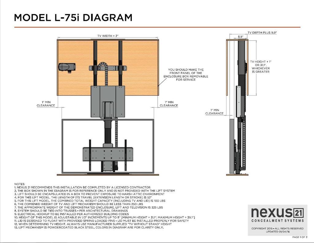
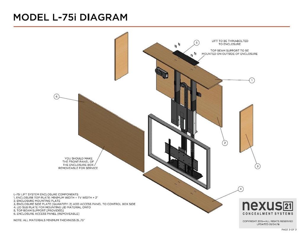
6 Assembly and Mounting Instructions DETAILED STEPS Preparing the Enclosure Box BEFORE BEGINNING, PLEASE READ THE SAFETY NOTICE ON THE FIRST PAGE OF THIS DOCUMENT The Enclosure Box for the TV and Lift System should be constructed of materials no less than ¾ thick. We recommend a high-grade plywood or combi-core material. The back and top of the enclosure are the parts that must be able to support the weight of the lift and TV, so MDF or particle board materials are not suitable for use in this project. The Enclosure Box dimensions depend on the size of your TV. Please review the Installation Dimensions Drawing on page 24 & 25 before beginning. IF YOU HAVE THE SPACE, WE RECOMMEND INCREASING EACH DIMENSION BY 1 TO MAKE FOR EASIER INSTALLATION AND SERVICE ACCESS. The End, Front and Back panels of the Enclosure Box should be attached to the underside of the Top Cover, so that the Top Cover is resting on top of the four panels. This provides the maximum strength for holding the Lift and TV in its inverted orientation. Step 1: Cut the five panels (#1 4) from ¾ plywood. Paint the inside of the panels a dark color before assembly. This will help camouflage the Enclosure Box after it is installed. Step 2: Determine where the electrical power will feed into the Enclosure Box. Cut out the appropriate sized opening near the top of the End Panel nearest the power feed. We recommend using a 110V duplex outlet and conduit that conform to the building code for your location. Step 3: Create a hinged front panel. a) This will provide convenient access to the electrical connections in the Control Box after installation. b) Put hinges and a latch (not provided) on the outside of the door so it opens OUT. c) Re-attach the Access Door to the Back Panel. Step 4: If a ventilation fan (not provided) is needed (in climates where attic temperatures exceed 110 degrees F), cut the opening for the fan near the top of the End Panel opposite the electrical feed. This will vent into the attic. 5
7 Table of Contents This Lift Model consists of three major systems, the Upper Actuation System, the Center Actuation System and the TV Mounting System. This instruction manual will cover how to build, install and wire the Lift. Installation and Assembly (Page 7-10) Assembling & Installing the Upper Actuation System (Page 11) Assembling the Center Actuation System (Page 12) Installing the Center Actuation System (Page 13-14) Calibrating and Synchronizing the Actuation Systems (Page 15-16) Managing the Motor Cables (Page 16) Re-calibrating & Re-synchronizing the Actuation Systems (Page 17) Assembling the TV Support System (Page 18) Installing the TV Support System (Page 19-21) Preparing the TV & Adjustments (Page 22-23) Installing the Lid & Lid Stabilization Assembly (Page 24-25) Dimensional Drawings (Page 26) Setting a Height Limit (Page 27) L-75i IR Wiring Diagram (Page 28) L-75i RF Wiring Diagram (Page 29) Contact Closure Integration Supplemental Information Wiring Diagrams 6
 Bayonet Sleeves (2) Lift Columns (Labeled A & B) Rear Support")
 5mm x 12mm FHMS (8) 10 x ¾ THWS Screws Step 1: Attach the Upper Cable")
 Bayonet Sleeves to the Rear Support Bracket using (4) 6 x 12 mm")

8 Assembling & Installing the Upper Actuation System For these steps, you will need the following parts: (2) Bayonet Sleeves (2) Lift Columns (Labeled A & B) Rear Support Bracket Top Beam Support (1) Cable Management Track (6) 6mm x 12mm BHMS (8) 6 x 40mm FHMS Screws (2) 5mm x 12mm FHMS (8) 10 x ¾ THWS Screws Step 1: Attach the Upper Cable Track Bracket to the Rear Support Bracket using (2) 6 x 12 mm BHMS screws. Step 2: Attach the (2) Bayonet Sleeves to the Rear Support Bracket using (4) 6 x 12 mm BHMS screws. Step 3: Stand both Lift Columns A & B upright and seat the pigtail grommets for each Lift Column so that they are both facing each other. Note: Columns A & B are interchangeable. 7


9 Step 4: Slide the tabs of the Rear Support Assembly down into the welded metal sleeve on each Lift Column. Step 5: Using a rubber mallet, tap each of the Bayonet Sleeves into the welded metal sleeves of each Lift Column until they are flush with the top of the metal sleeve on the Lift Columns. Step 6: Center the Top Beam Support on the top panel on the interior of the enclosure. Important Note: Ensure the edge of the Top Beam Support, farthest from the mounting holes is ½ away from the back panel of the enclosure. See right photo for reference. 8

 drilled")

 6 x 40mm FHMS")

10 Step 7: Using a 7/32 Drill Bit, drill out all (8) mounting holes for the Top Beam Support. Step 8: Now place the Top Beam Support on the top panel on the exterior of the enclosure, aligning it with the (8) drilled holes. Step 9: Place the Upper Lift Columns with the attached Rear Support Bracket into the enclosure Align them with the holes drilled for the Top Beam Support and using (8) 6 x 40mm FHMS Screws, through bolt them to the top panel You will need a 2nd person to hold the lift system while the screws are fastened. Note: Leave these screws slightly loose to assist with attaching the Center Actuation System. 9


11 Step 10: Level each Lift Column horizontally within the enclosure, then fasten the Rear Support Bracket to the back panel of the enclosure using (8) 10 x ¾ THWS Screws. Step 11: Attach the Upper Cable Management Track to the Center Cable Track Bracket on the Rear Support Assembly using (2) 5mm x 12mm FHMS. Ensure the Upper Cable Management Track bends initially then hangs. The Upper Lift Columns are now successfully installed. 10
 Lift Column (Labeled C) Center Cable Track Bracket")
 Step 12: Slide the Bayonet Bracket into the welded")

 6 x 20mm")


12 Assembling the Center Actuation System For these steps, you will need the following parts: Center Riser Bracket (1) Lift Column (Labeled C) Center Cable Track Bracket Bayonet Bracket (8) 6mm x 20mm FHMS (4) 5 x 12mm FHMS Screws Small Hex Key and 5mm Hex Key Rubber Mallet (Not Included) Step 12: Slide the Bayonet Bracket into the welded metal sleeves of the Center Lift Column C. Using a rubber mallet, tap the Bayonet Bracket into the welded metal sleeves until they are flush with the top of the metal sleeve on the Lift Columns. Step 13: Attach the Center Lift Column C to the Center Riser Bracket using (4) 6 x 20mm FHMS Screws. Step 14: Attach the Center Cable Track Bracket to the back of the Center Riser Bracket using (2) 6 x 16mm BHMS Screws and (2) ¼ Flat Washers. Now seat the pigtail grommet for the Center Lift Column C so that it is facing the back panel of the enclosure. Note: The Center Cable Track Bracket should look identical to the photo. (Color Changed for reference). The Center Actuation System is now assembled and ready to be installed. 11
")


 5 x 12mm FHMS")

13 Installing the Center Actuation System For these steps, you will need the following parts: Center Actuation System (8) 6mm x 20mm FHMS (4) 5 x 12mm FHMS Screws (1) Cable Management Track Small Hex Key and 5mm Hex Key Step 15: Attach the Center Actuation System to Upper Actuation System using (8) 6 x 20mm FHMS Screws. After the Center Actuation System has been attached fasten the screws for the Top Beam Support. Step 16: Attach the Upper Cable Management Track to the Upper Tab of the Center Cable Track Bracket using (2) 5 x 12mm FHMS Screws. Step 17: Attach the Lower Cable Management Track to the Lower Tab of the Center Cable Track Bracket using (2) 5 x 12mm FHMS Screws. You have successfully installed the Center Actuation System. 12


14 Calibrating and Synchronizing the Actuation Systems For these steps, you will need the following parts: (2) 2000mm Motor Cables (1) 2500mm Motor Cable Control Box Power Cord Wired Backup Switch (2) #10 x 1 ¾ FHWS Screw In order to calibrate and synchronize the systems together, you will need to mount your Control Box to the enclosure. We recommend mounting the Control Box on the left side of the enclosure to make cable management easier. Note: All installations are different and the Control Box may be mounted base upon your preference and electrical outlet accessibility. Longer Motor Cables are available upon request. Once your Control Box is mounted you are ready to connect the Motor Cables to each Lift Column. Note: You will not need to route the Motor Cables through the Cable Management Tracks at this time as this will be covered in later steps. We do recommend marking each cable with a tag to label which port it is connected to thought. Step 18: Locate the pigtails for the Upper Lift Columns (A & B) and connect the Upper Right Lift Column to port 1 and the Upper Left Lift Column to port 2 on the Control Box using the (2) 2000mm Motor Cables. Refer to page (25 and 26) for a Wiring Diagram Step 19: Locate the pigtail for the Center Lift Column (C) and connect it to port 3 on the Control Box using the 2500mm Motor Cable. 13

15 Step 20: Connect the Wired Backup Switch to either port A1 or A2 on the Control Box. Note: You may use the bag labeled Extension Pack to increase the length of the Wired Backup Switch for easier use or to remotely mount it. Step 21: Press and hold the button without the raised dot on the Wired Backup Switch for 10 seconds. You should see a slight movement from the lift system but do not release the button until 10 seconds have elapsed. Note: If you do not see the movement on the first attempt, release the down button and try this step again. It may take 2 or 3 tries. Ensure no cables are tangled on any brackets of the Lift System, then extend the Lift System by pressing the button with the raised dot on the Wired Backup Switch to fully extend the lift. Note: If you need to stop the lift at any time you may do so by pressing the button without the raised dot. You have now successfully calibrated and synchronized the Lift System. 14


16 Managing the Motor Cables Now that the lift has been calibrated and extended it will be easier to fish the Motor Cables through their respective Cable Management Tracks. Step 22: Before doing this however, ensure the Lift System is level relative to the enclosure by placing a level on the top of the Center Riser Bracket. Note: If your lift is not level, you may need to check the level of the Upper Columns again. If the Upper Columns are level, loosen the screws to the Center Actuation System ¼ turn and retry the step 30 again. Once the level of the Lift System has been checked, you are now ready to route the Motor Cables through the Cable Management Tracks. Step 23: Disconnect all of the motor cables from the pigtails on each of the Lift Columns, leaving them only connected to the Control Box. Note: We recommend marking each cable with a tag to label which port it is connected to. Step 24: Take the Motor Cables connected to ports 1, 2, and 3 on the Control Box and fish them through the Upper Cable Management Track one by one. Step 25: Take the Motor Cable connected to port 1 and run it through the hole on the left side of the Center Riser Bracket, across the front of the Center Lift Column, and through the hole on the right side of the Center Riser Bracket then connect it to the Upper Right Lift Column s pigtail. 15


17 Step 26: Take the Motor Cable connected to port 2 and connect it to the Upper Left Lift Column s pigtail. Step 27: Take the Motor Cable connected to port 3, fish it through the Lower Cable Management Track, and connect it to the Center Lift Column s pigtail. You have successfully connected and managed the Lift Systems cabling. Re-Calibrate & Re-synchronizing the Lift System After the Motor Cables are routed and re-connected to each column you will need to reinitialize them again. Step 28: Fully retract the lift by pressing the button without the raised dot on the Wired Backup Switch. Note: The Lift may be in Safe Mode which means you will need to keep the button without the raised dot on the Wired Backup Switch held until the lift fully retracts. Once the lift is fully retracted, press and hold the button without the raised dot on the Wired Backup Switch for 10 seconds. You should see a slight movement from the lift system but do not release the button until 10 seconds have elapsed. Note: If you do not see the movement on the first attempt, release the down button and try this step again. It may take 2 or 3 tries. You have successfully re-synchronized and reinitialized the lift system. 16
 3/8-16 ¾ BHMS 38 Step 29: Attach both Top Support Brackets to the Screen Support using (6) 6 x 12mm BHMS Screws.")
 6 x 12mm BHMS Screws to attach the Top Support Brackets. Step 30: Attach the Screen Back Plate to the Screen Support using (4) 3/8-16 ¾ BHMS.")
18 Assembling the TV Support System For these steps, you will need the following parts: (2) Top Support Brackets (2) Lift Columns (Labeled A & B) Screen Support Screen Back Plate (6) 6mm x 12mm BHMS (4) 3/8-16 ¾ BHMS 38 Step 29: Attach both Top Support Brackets to the Screen Support using (6) 6 x 12mm BHMS Screws. As long as the Top Support Brackets are in-line, you can use any set of holes. Adjustments will be covered in a later section. Note: You must use ALL (6) 6 x 12mm BHMS Screws to attach the Top Support Brackets. Step 30: Attach the Screen Back Plate to the Screen Support using (4) 3/8-16 ¾ BHMS. Once again use any sets of holes as adjustments will be covered in a later section. You have successfully assembled the TV Support System. 17
 6 x 20mm BHMS Step 31: Attach the TV Support System to the Center Lift")

19 Installing the TV Support System For these steps, you will need the following parts: TV Support System (4) 6 x 20mm BHMS Step 31: Attach the TV Support System to the Center Lift Column using (4) 6 x 20mm BHMS. Once again making sure the pigtail for the Center Lift Column is facing the back panel of the enclosure. You have successfully installed the TV Support System. 18


20 Preparing the TV & Adjustments For these steps, you will need the following parts: Lower Cable Track Bracket Vertical Mounting Bars Front Cover Lid Plate (5) 6 x 12mm BHMS Screws (4) 6 x 12mm FHMS Screws TV Mounting Hardware Before you mount the TV to the Lift System you will need to know more about adjustability of the lift. There are 2 points of adjustment on the L-75i; The Top Support Brackets, which can be adjust up and down in ½ increments up to a total of 8 and the Screen Back Plate which can also be adjusted up or down depending on the mounting pattern of your TV. Step 32: Attach the Vertical Mounting Bars to the TV using the screws found in the bag labeled TV Mounting Screws Hardware. The length and size of the screw required will depend on whether the TV has a flat/unobstructed or irregular/obstructed back. A Flat/Unobstructed Back Diagram A installation procedure: 1) Place the flat screen TV face down on a protected surface. 2) Position the Vertical Mounting Bars equidistant from the bottom and top of the TV, with the slots facing toward the top of the TV. 3) Using the four (4) Square Multi-Mount washers and the TV mounting screws selected from the bag, attach and tighten the hardware. DO NOT OVERTIGTHEN HARDWARE. DAMAGE TO TV MAY RESULT. 19
 Position the Vertical Mounting Bars equidistant from the bottom and top of the TV, with the slots facing toward the top of the TV.")
: TV, Spacers, Vertical Mounting Bars, Square Multi-Mount Washers, TV Mounting Screws. DO NOT OVERTIGTHEN HARDWARE.")
21 B Irregular/Obstructed Back Diagram B installation procedure: 1) Place the flat screen TV face down on a protected surface. 2) Position the Vertical Mounting Bars equidistant from the bottom and top of the TV, with the slots facing toward the top of the TV. 3) Using the four (4) spacers needed, (4) Square Multi-Mount washers and the TV mounting screws selected from the bag, attach and tighten the hardware. The hardware will be used in this order (as shown in the diagram above): TV, Spacers, Vertical Mounting Bars, Square Multi-Mount Washers, TV Mounting Screws. DO NOT OVERTIGTHEN HARDWARE. DAMAGE TO TV MAY RESULT. Step 33: Hang the TV on the Screen Back Plate by the Vertical Mounting Bars. Ensure both sets of hooks are on the channels of the Screen Back Plate. You may need to adjust the Screen Back Plate at this point to adjust the viewing position of the TV. Step 34: Once the TV has been mounted and adjusted to its final viewing position, adjust the Top Support Brackets so that they are ¼ to ½ above the bottom of the enclosure. Step 35: Once you have made the necessary adjustments to the Top Supports, remove the TV from the lift. Step 36: Fully extend the lift by pressing the button with the raised dot on the Wired Backup Switch. 20
 5 x 12mm FHMS.")
 6 x 12mm BHMS Screws.")


22 Step 45: Attach the Lower Cable Track Bracket to the Lower Cable Track using (2) 5 x 12mm FHMS. Step 37: Attach the Lower Cable Track Bracket to the Right Top Support Bracket using (3) 6 x 12mm BHMS Screws. Note: Ensure the Lower Cable Management Track does not have any slack, but is not so tight that it deforms the radial bend at the top of it. Step 38: Attach the Front Cover to the Center Riser Bracket using (2) 6 x 12mm BHMS Screws. Step 39: Retract the lift by pressing the button without the raised dot on the Wired Backup Switch. Step 40: Attach the Lid Plate to the Top Support Brackets using (4) 6 x 12mm FHMS Screws. Note: The Lid Plate will overhang on the back end of the lift so that the mounting holes in the 4 corners of the Lid Plate sit behind the TV. 21


23 Installing the Lid & Lid Stabilization Assembly For these steps, you will need the following parts: (4) Shoulder Bolt (4) ½ Nylon Spacers (4)Lid Stabilization Springs (4) Brass Threaded Inserts Your Lid Important Info: You must have your TV mounted when installing your lid as the additional weight from the TV may cause the lid to shift throwing all measurements off. The Lid Stabilization Assemblies are spring loaded so the Ceiling Cut-out will stop level with the ceiling and allow the Lift to travel an additional 1/8 1/2 up into the ceiling. You should create a stop, or lip above the ceiling, around the edge of the opening for your Ceiling Cover to pull up against, like an upside-down manhole cover. The illustration on the left shows how it should work, and details for assembly are shown on the following pages. Most Contractors use a 45 degree bevel on both the lid and the ceiling cutout so the lid self-centers when retracting into its recess. There are other ways of doing this. This is just a recommendation and it may or may not be able to be done based on the material of the lid. Step 41: Re-hang the TV on the Screen Back Plate and place the Screen Locks in the bottom set of hooks of the Vertical Mounting Bars. Step 42: Fasten the Screen Locks using a philips screw driver, this will secure and lock the TV onto the Screen Back Plate. 22
.")


24 Step 43: Mark and drill (4) ½ holes on your Lid Material: Hold your lid piece (your ceiling cut-out piece) up to the Lid Plate (which you have already installed on the Lift, and is now hanging out of the ceiling). The Lid Plate has 4 holes that are used to attach your lid piece. Mark the position of the holes on your lid piece. Drill four holes ½ deep using a 1/2 drill bit. Step 44: Screw the Four (4) Brass Inserts into the (4) ½ holes using a flat head screwdriver or keep the brass insert screwed to the bolt and use a 3/16 Allen Wrench to drive the brass insert into the lid. Tighten them down until the tops of the Brass Inserts are flush with the surface of the lid piece. Step 45: Attach your lid to the bottom of the Lid Plate. Screw the (4) Shoulder Bolts with springs attached through the Lid Plate into the Brass Inserts previously installed in step 27b. NOTE: Depending on the weight of your lid material you may need to use a nylon spacer between the top of the spring and the head of the bolt, to tighten the tension of the spring which will give the lid more stability preventing the lid from sagging. (Example photo to the right.) Spacers You have successfully installed the lid and lid stabilization assembly. 23
25 24
26 25


27 Please follow this procedure if you would like to limit the distance that your TV Lift extends. To set your Travel Limit with IR Controls: If you want the lift system to always go to its full extension, do NOT use the Height Limit Insert. Simply leave it unplugged and the system will always travel to the full extension. To limit the travel, follow the procedure below: 1. Using the IR Receiver, run the lift system to the ideal height limit position and stop it there. 2. With the lift system stopped, plug the Height Limit Insert into the available RJ45 port on the Control Box. This will set the height limit at this position for both the IR Remote (or 3 rd party universal remote) and the IR Receiver. 3. If the height limit is set at the incorrect position, remove the Height Limit insert and repeat the procedure. To set your Travel Limit with RF Controls: If you want the lift system to always go to its full extension, do NOT use the Height Limit Insert. Simply leave it unplugged and the system will always travel to the full extension. To limit the travel, follow the procedure below: 1. Using the Wired Backup Switch, run the lift system to the ideal height limit position and stop it there. 2. With the lift system stopped, plug the Height Limit Insert into the available RJ45 port on the RF Receiver. This will set the height limit at this position for both the RF Remote and Backup Switch. 3. If the height limit is set at the incorrect position, remove the Height Limit insert and repeat the procedure. 26
 prior to inserting.")
28 Ports A1 & A2 are interchangeable To Power Outlet Height Limit Insert Note: Read page (26) prior to inserting. Lift Column C IR Receiver Lift Column A or B Lift Column A or B 27

29 Ports A1 & A2 are interchangeable To Power Outlet Height Limit Insert Note: Read page (26) prior to inserting. Lift Column C Lift Column A or B Lift Column A or B Backup Switch RF Receiver 28

30 29
31 30 (Intentionally left blank)
32 31 (Intentionally left blank)
33
INSTALLATION INSTRUCTIONS
 INSTALLATION INSTRUCTIONS Universal Short Throw Projector Wall Mount Model: NORTH AMERICA 3130 East Miraloma Avenue Anaheim, CA 92806 USA USA and Canada Phone: 1-800-368-9700 Fax: 1-800-832-4888 Other
Mobile TV Mount Stand with Hydraulic Height Adjustment Model: DMS-172
 Mobile TV Mount Stand with Hydraulic Height Adjustment Model: DMS-172 Instruction Manual Images may be different from actual product Disclaimer It is Dyconn s intention to have all the correct information
OPERATOR S MANUAL. 20-bu 3-Point Hitch Material Collection System. LP65048 Supplier ST /07/2017 English. North American Edition Printed in USA
 OPERATOR S MANUAL 20-bu 3-Point Hitch Material Collection System LP65048 Supplier ST48289 11/07/2017 English North American Edition Printed in USA Introduction Using Your Operator s Manual Read this entire
Down and Out Motor Mount Assembly & Installation Directions
 Down and Out Motor Mount Assembly & Installation Directions Mounting the Down and Out Motor Mount correctly takes a lot of thought and a lot of planning. Please read the directions thoroughly and plan
UNPACK AND IDENTIFY THE FOLLOWING PARTS.
 SUT-250-M2 ASSEMBLY REQUIREMENTS *Torque all T-bolt nuts to 35-40 foot pounds. *Check all lights before towing. *Tire pressure not to exceed recommendation on serial tag. *Re-torque wheel nuts after first
LSL PF - Lift System Light Push Flap
 Installation Instructions LSL PF - Lift System Light Push Flap Design Highlights -Quiet Smooth Action at Approximately 40mm [1.6 ] per Second -Full Cable Management -Wide Range of Mounting Options -24V
ARION: 19 EIA-310E Standard Enclosure
 Patents Pending: 1002000994, 1001000784, 1001000785, 1001000786, 1001000787 UL 2416 Approved Part No. TBA Publication Date: March, 2015 User Manual 1 Contents Page Important Safety Information..............................................
Fiber Splice Panel Rack Mount User Manual
 Fiber Splice Panel Rack Mount User Manual Content Page INTRODUCTION... 1 Revision History... 1 List of Changes... 1 Trademark Information... 2 Admonishments... 2 1. DESCRIPTION... 2 A. Product Definition
LSM PF - Lift System Medium Push Flap
 Installation Instructions LSM PF - Lift System Medium Push Flap Design Highlights -Quiet Smooth Action at Approximately 40mm [1.6 ] per Second -Full Cable Management -Wide Range of Mounting Options -24V
Automatic Roof Hatch Opener
 Automatic Roof Hatch Opener Installation Guide REQUIRED TOOLS (These tools are required to complete the installation) Cordless Drill 1/8 1/4 Drill Bits 1/8 Pin Punch #2 Philips Bit Rachet Sharpie Hammer
LSL EFA - Lift System Light Electric Flap Actuator
 Installation Instructions LSL EFA - Lift System Light Electric Flap Actuator Design Highlights -Quiet Smooth Action at Approximately 40mm [1.6 ] per Second -Full Cable Management -Wide Range of Mounting
PM - Projector Mount System
 Installation Instructions PM - Projector Mount System Design Highlights -Beautiful Anodised Aluminium Finish -Complete Lead-Screw Adjustment of All Pitches of Angle -Range of Fixed and Telescopic Poles
Installation Instructions Table of Contents
 Installation Instructions Table of Contents Pre- Installation of Garage Storage Lift 2 Layout the Garage Storage Lift 3 Installing the strut Channels 3 Install the Drive Assembly 5 Install the Drive Shaft
Anthro Mobile Device Charging Carts and Cabinets Owners Manual
 Anthro Mobile Device Charging Carts and Cabinets Owners Manual TECHNOLOGY FURNITURE Hello! Thank you for choosing Anthro. Anthro's Tablet Charging Carts and Cabinets are designed to automatically charge
Instructions for 2-row monitoring only
 Installation Instructions for CaseIH cotton picker models: Instructions for 2-row monitoring only CAUTION: Ensure the model numbers shown above correspond to the machine model. If you receive the incorrect
FOR SIT-STAND WORKSTATION
 INSTALLATION MANUAL FOR SIT-STAND WORKSTATION Weight Capacity: 6.5-24.5 lbs. 6017180 Rev. B Contents Tools Required / Supplied Part Kits / Warnings/Disclaimers...2 Base Installation Clamp Mount Base Location...3
Installation Manual. For. Trident Boat Lifts
 Installation Manual For Trident Boat Lifts Page 2 Safety Precautions 1. Your boat lift is a heavy duty piece of equipment. It is important that all persons that may operate this unit have read and understood
INSTALLATION & OWNER S MANUAL
 INDUSTRIES, LLC. INSTALLATION & OWNER S MANUAL CAB INSTALLATION INSTRUCTIONS KUBOTA GRAND L 40 SERIES HARD SIDED CAB ENCLOSURE (p/n 1KGL4AS) This Curtis Cab is designed and manufactured for use only as
A B C D E F. Tools Required (supplied by others)
") Page 1 of 17 Parts List Below Deck Automatic Retractable Security Cover Kit (1) Tube End Bearing Plate (A) (1) Rope Reel and Cover Drum Motor Assembly (B) (1) Cover Drum (1) Pulley Support Channel (2)
Page 1 of 17 Parts List Below Deck Automatic Retractable Security Cover Kit (1) Tube End Bearing Plate (A) (1) Rope Reel and Cover Drum Motor Assembly (B) (1) Cover Drum (1) Pulley Support Channel (2)
Assembly Instructions
 Assembly Instructions Part Number Description Model Approx. Assembly Time 99994-0903 Windshield Wiper Kit Mule SX 1 Hour WARNING Improper installation of this accessory could result in an accident causing
Plasma Dual Swing-Out (PDS Series) Wall Mount
 Wall Mount") INSTALLATION INSTRUCTIONS Plasma Dual Swing-Out ( Series) Wall Mount The wall mount is a rugged, versatile, and installer-friendly solution to unique display mounting requirements. In addition to providing
INSTALLATION INSTRUCTIONS Plasma Dual Swing-Out ( Series) Wall Mount The wall mount is a rugged, versatile, and installer-friendly solution to unique display mounting requirements. In addition to providing
AGCO. Corn Header Manual d HEADSIGHT.COM
 AGCO Corn Header Manual 09020401d HEADSIGHT.COM 574.546.5022 About Headsight Headsight Contact Info Headsight, Inc. 4845 3B Road Bremen, IN 46506 Phone: 574-546-5022 Fax: 574-546-5760 Email: info@headsight.com
Installation Instructions. Attention Dealers: Please give this owners manual to the customer when the product is delivered.
 Serving the Truck & Trailer Industry Since 1944 Attention Dealers: Please give this owners manual to the customer when the product is delivered. Call 800-535-9545 www.aeroindustries.com Indianapolis, IN
STACK-ON UNIT WARNING. Illustration 1
 Illustration 1 Illustration 2 End panel label Sound deadening material (do not remove) RH RH Read all instructions and review illustrations before installing. Tools required for assembly: Phillips driver
MOTORIZED FOLDING CAMPER WINCH
 OWNER'S MANUAL MOTORIZED FOLDING CAMPER WINCH With 1200lb Lift Capacity The 12 Volt Motorized Folding Camper Winch is used to raise and lower folding campers with the touch of the switch, eliminating hand
36" Galvanized Direct Drive Hyflo Fan Installation and Operators Instruction Manual. Fan and Framing Dimensions
 6" Galvanized Direct Drive Hyflo Fan Installation and Operators Instruction Manual Fan and Framing Dimensions Planning the layout of the spacing between Fans is very important. Spacing too close together
INSTALLATION INSTRUCTIONS
 AUTOMOTIVE PRODUCTS, INC. INSTALLATION INSTRUCTIONS ULTIMATE BULL BAR APPLICATION: 2017 Ford F-250/350 PART NUMBER: 32-3900, 32-3905, 32-3900L, 32-3905L ITEM QUANTITY DESCRIPTION TOOLS NEEDED 1 1 ULTIMATE
Siderolling Tarp Systems Under 9 6 Wide
 Load Loc Select Maximizer Grain Carts Grain Bagger Siderolling Tarp Systems Under 9 6 Wide CRANK STYLE INSTALLATION INSTRUCTIONS MICHEL S INDUSTRIES, LTD. P.O. BOX 119 ST. GREGOR, SK. S0K 3X0 PH:306.366.2184
Instructions for 2-row monitoring only
 Installation Instructions for CaseIH cotton picker models: Instructions for 2-row monitoring only Ensure the model numbers shown above correspond to the machine model. If you receive the incorrect installation
Plasma Display Electric Pop-Up Lift (PUL)
") I N S T R U C T I O N M A N U A L Plasma Display Electric Pop-Up Lift (PUL) Your is designed for installation in furniture or cabinets. Display mounting is made easy using the Q-latch mounting system and
I N S T R U C T I O N M A N U A L Plasma Display Electric Pop-Up Lift (PUL) Your is designed for installation in furniture or cabinets. Display mounting is made easy using the Q-latch mounting system and
FL2000 Termination/Splice Panels User Manual
 FL2000 Termination/Splice Panels User Manual Content Page INTRODUCTION... 1 Revision History... 1 List of Changes... 1 Trademark Information... 2 Related Publications... 2 Admonishments... 2 General Safety
2-row and All-row systems included.
 Ag Leader Technology Cotton Picker Installation Installation Instructions for John Deere cotton picker models: 2-row and All-row systems included. IMPORTANT: Ensure the model numbers shown above correspond
EASYBIRD AUTO-FEED 6 - PACKER Part No (40912 with Oscillating Base)
") EASYBIRD AUTO-FEED 6 - PACKER Part No. 40911 (40912 with Oscillating Base) Instruction Manual WARNING! THIS MACHINE CAN CAUSE SERIOUS INJURY OR DEATH. THOROUGHLY READ INSTRUCTIONS BEFORE INSTALLING OR
EASYBIRD AUTO-FEED 6 - PACKER Part No. 40911 (40912 with Oscillating Base) Instruction Manual WARNING! THIS MACHINE CAN CAUSE SERIOUS INJURY OR DEATH. THOROUGHLY READ INSTRUCTIONS BEFORE INSTALLING OR
Feed Scale Installation & Operator s Instruction Manual
 Installation & Operator s Instruction Manual May 004 CTB Inc. Warranty CTB Inc. Warranty CTB Inc. warrants each new C-Collect product manufactured by it to be free from defects in material or workmanship
Please visit for the latest version of these installation instructions.
 Please visit www.blueox.com for the latest version of these installation instructions. BX3796 Attachment Tab Height: 13-1/2 Serial Number Attachment Tab Width: 24 Please read BOTH these and the General
Installation Instructions LSM TU EFA - Lift System Medium Telescopic Unit Electric Flap Actuator
 Installation Instructions LSM TU EFA - Lift System Medium Telescopic Unit Electric Flap Actuator Design Highlights -Quiet Smooth Action at Approximately 40mm [1.6 ] per Second -Full Cable Management -Wide
UNPACK AND IDENTIFY THE FOLLOWING PARTS.
 SUT-500-S ASSEMBLY REQUIREMENTS *Torque all T-bolt nuts to 35-40 foot pounds. *Check all lights before towing. *Tire pressure not to exceed recommendation on serial tag. *Re-torque wheel nuts after first
INSTALLATION & OWNER S MANUAL
 Rev. B, p. 1 of 25 INSTALLATION & OWNER S MANUAL POLARIS RANGER RCS (for models XP or HD) (for model years 2009-) cab without doors kit (p/n 1POLRCWD) cab with doors kit (p/n 1POLRC) doors only kit (p/n
Installation and Service Manual
 RAVE Stair Lift Installation and Service Manual WARNING! STRICT ADHERENCE TO THESE INSTALLATIONS INSTRUCTIONS IS REQUIRED to promote the safety of those installing this product, as well as that of those
Cetra Assembly Instructions
 99877 Revision F- Complete Series Master Packet If you have any questions concerning these instructions, please call Kimball Office Customer Service. 0 Kimball International, Inc. T 800.8.88 F 8.8.800
A B C D E F. b.tools Required (supplied by others) 3/16" Drill Bit 3/8" Wrench Phillips Head Screwdriver
 3/16 Drill Bit 3/8 Wrench Phillips Head Screwdriver") Page 1 of 13 5E.1 Parts List a. Below Deck Automatic Retractable Security Cover Kit (1) Tube End Bearing Plate (A) (1) Rope Reel with Motor Attached (B) (1) Rope Reel Cover (C) (1) Cover Drum (1) Cover
Page 1 of 13 5E.1 Parts List a. Below Deck Automatic Retractable Security Cover Kit (1) Tube End Bearing Plate (A) (1) Rope Reel with Motor Attached (B) (1) Rope Reel Cover (C) (1) Cover Drum (1) Cover
INSTALLATION & OWNER S MANUAL
 Rev. C p. 1 of 21 INSTALLATION & OWNER S MANUAL F5205 HARD SIDED CAB KIT INSTALLATION & OWNER S MANUAL The contents of this envelope are the property of the owner. Be sure to leave with the owner when
NORTHSTAR TRAILERS. Assembly Guide for SPORTSTAR II Trailer
 NORTHSTAR TRAILERS Assembly Guide for SPORTSTAR II Trailer Congratulations! You are the proud owner of a NORTHSTAR trailer. Please follow the instructions and steps in this manual for proper assembly.
INSTALLATION GUIDE TCP RCKM-01
 READ ALL INSTRUCTIONS COMPLETELY AND THOROUGHLY UNDERSTAND THEM BEFORE DOING ANYTHING. CALL TOTAL CONTROL PRODUCTS TECH SUPPORT (916) 388-0288 IF YOU NEED ASSISTANCE. INSTALLATION GUIDE TCP RCKM-01 Manual
INSTALLATION INSTRUCTIONS
 PART NO. 23100T PRODUCT DESCRIPTION: Front Winch Bumper, Center Section PRODUCT SAFETY & LEGAL DISCLAIMER IMPORTANT READ ALL INSTRUCTIONS CAREFULLY BEFORE INSTALLING, FAILURE TO DO SO MAY CAUSE PERSONAL
INSTALLATION MANUAL ALUMINUM & STEEL SIDE BOX
 TRUCK STORAGE SOLUTIONS SECURING YOUR REPUTATION INSTALLATION MANUAL ALUMINUM & STEEL SIDE BOX STEEL & ALUMINUM SIDE BOX WITH PACK RAT DRAWER UNITS MODELS ATTENTION: PLEASE READ AND UNDERSTAND ALL INSTRUCTIONS
Model A Turn Signal Kit Installation Guide
 Model A Turn Signal Kit Installation Guide Creative Connections, Inc. Consumer Hot Line: 888-471-LOGO 770-476-7322 In Atlanta, GA http://www.logolites.com P/N: 100-005/K 2008 Creative Connections, Inc.
Installation Instructions Studio Makeup Station
 Installation Instructions Studio Makeup Station 30" and 36" Models 5-light 30" Studio Makeup Station 8-light 30" Studio Makeup Station 6-light 36" Studio Makeup Station 9-light 36" Studio Makeup Station
INSTALLATION INSTRUCTIONS AND OWNER S MANUAL
 INSTALLATION INSTRUCTIONS AND OWNER S MANUAL Thank you for purchasing the AlloyCover from WeatherTech. Manufactured with pride using superior quality materials and workmanship. With proper care, your cover
INSTALLATION INSTRUCTIONS
 INSTALLATION INSTRUCTIONS Single-Stud/Dual-Stud Short-Throw Projector Wall Mount Model: EST100/EST200 NORTH AMERICA 3130 East Miraloma Avenue Anaheim, CA 92806 USA USA and Canada Phone: 1-800-368-9700
INSTALLATION FORK MOUNTED DRIVING LIGHTS 5008
 5008 PARTS INCLUDED 1 Right Fork Mount Assembly 1 Left Fork Mount Assembly 2 H3 Driving Light Assemblies 1 12-Pin Wiring Adapter 1 Hardware Kit for Fork Mount Driving Lights, Including: 6 5/16-18 Nylock
INSTALLATION INSTRUCTIONS
 144F TABLE OF CONTENTS GENERAL... 2 SPECIFICATIONS... 2 PACKAGE CONTENTS... 2 PACKAGE CONTENTS: ACCESSORIES... 3 REQUIRED TOOLS... 3 ADD-ON COMPONENTS... 3 CABINET MOUNTING WALL MOUNT BRACKET ATTACHMENT...
Turbo-House Air Inlet Installation & Operator s Instruction Manual
 Turbo-House Air Inlet Installation & Operator s Instruction Manual October 2011 Chore-Time Warranty Turbo-House Air Inlet Chore-Time Warranty Chore-Time Equipment ( Chore-Time ) warrants each new Chore-Time
Please visit for the latest version of these installation instructions.
 Please visit www.blueox.com for the latest version of these installation instructions. Attachment Tab Height: 25 Serial Number Attachment Tab Width: 22-1/2 Please read BOTH these and the General Information
*Enclosed pictures and devices are for reference only. Individual vehicles and devices may vary.
 Dash Strap Mount Product Number AS5.S500.001 *Enclosed pictures and devices are for reference only. Individual vehicles and devices may vary. The Dash Strap Mount is held tight against the vehicle dash
TGS 1100 & TGS 600 TAILGATE SPREADER INSTALLATION & OWNER S MANUAL
 BOSS PRODUCTS A Division of Northern Star Industries, Inc. P.O. Box 787 Iron Mountain MI 49801-0787 www.bossplow.com TGS 1100 & TGS 600 TAILGATE SPREADER INSTALLATION & OWNER S MANUAL TABLE OF CONTENTS
The RICON Eclipse F8000 (A) Series Export Use Wheelchair and Standee Lift is installed in a
 Series Export Use Wheelchair and Standee Lift is installed in a") II. INSTALLATION TABLE OF CONTENTS The RICON Eclipse F8000 (A) Series Export Use Wheelchair and Standee Lift is installed in a cassette mounted to the underside of the vehicle and behind the bottom step
II. INSTALLATION TABLE OF CONTENTS The RICON Eclipse F8000 (A) Series Export Use Wheelchair and Standee Lift is installed in a cassette mounted to the underside of the vehicle and behind the bottom step
LPE C5 Battery Relocation Kit
 LPE C5 Battery Relocation Kit The LPE C5 Corvette battery relocation kit improves vehicle weight distribution by moving weight to the rear of the vehicle. The improved weight distribution increases traction
Linear Actuator. Installation Manual. warranty installation parts list. Linear Actuator Installation Manual Page 1
 Linear Actuator Installation Manual warranty installation parts list January 2004 Linear Actuator Installation Manual Page 1 MA1221B12 Warranty Information Chore-Time Equipment ( Chore-Time ) warrants
Installation Manual. For. Alumavator / Platinum Boathouse Lifts
 Installation Manual For Alumavator / Platinum Boathouse Lifts Page 2 Safety Precautions 1. Your boat lift is a heavy duty piece of equipment. It is important that all persons that may operate this unit
TAILGATE SPREADER INSTALLATION & OWNER S MANUAL TABLE OF CONTENTS
 A Division of Northern Star Industries, Inc. P.O. Box 788 Iron Mountain MI 49801-0788 www.bossplow.com SMARTHITCH 1100 TAILGATE SPREADER INSTALLATION & OWNER S MANUAL TABLE OF CONTENTS S & CAUTIONS...
1000 Park Drive Lawrence, PA Fax
 Copyright 2008. Black Box Corporation. All rights reserved. 1000 Park Drive Lawrence, PA 15055-1018 724-746-5500 Fax 724-746-0746 JANUARY 2008 RM810A-R2 RM825A-R2 RM840A-R2 RM855A-R2 RM812A-R2 RM825A-3F-R2
FIGURE 2-1: LIFT (LEFT-SIDE) MOUNTING HOLES
 MOUNTING HOLES") II. INSTALLATION T he RICON Mirage F9A Series Transit Use Wheelchair and Standee Lift is installed in a cassette mounted to the underside of the vehicle and behind the bottom step riser. Due to the wide
II. INSTALLATION T he RICON Mirage F9A Series Transit Use Wheelchair and Standee Lift is installed in a cassette mounted to the underside of the vehicle and behind the bottom step riser. Due to the wide
SERVICE MANUAL SL220-SK6. Lift Assembly Replacement
 SERVICE MANUAL Lift Assembly Replacement Spanish Product Description German Product Description Portuguese Product Description Italian Product Description Dutch Product Description French Product Description
ENCLOSURES & PANELS. The Trusted Source for Innovative Control Solutions
 ENCLOSURES & PANELS The Trusted Source for Innovative Control Solutions 1-717-767-6511 999 This page intentionally left blank. 1000 www.redlion.net MODEL ENC13 - NEMA 4 ENCLOSURES FOR CUB7 This enclosure
Suzuki Samurai to Toyota Front Spring Swap Kit, with Missing Link Shackles (SKU#SSP-TSFM) Installation Instructions
 Installation Instructions") Suzuki Samurai to Toyota Front Spring Swap Kit, with Missing Link Shackles (SKU#SSP-TSFM) Installation Instructions CAUTION: Safety glasses should be worn at all times when working with vehicles and related
Suzuki Samurai to Toyota Front Spring Swap Kit, with Missing Link Shackles (SKU#SSP-TSFM) Installation Instructions CAUTION: Safety glasses should be worn at all times when working with vehicles and related
8400 Series Fiber Distribution System
 8400 Series Fiber Distribution System Instructions January 1997 34-7041-4699-1-A 1 Contents: 1.0 General... 3 2.0 System Components... 4 3.0 System Engineering... 5 4.0 Hardware Installation... 7 5.0 Cable
JEEVES. JEEVES Installation Manual. Installation Manual The Easiest Do-It-Yourself Dumbwaiter on the Market
 1 888-323-8755 www.nwlifts.com JEEVES Installation Manual The Easiest Do-It-Yourself Dumbwaiter on the Market This manual will cover the installation procedure step-by-step. The installation of this dumbwaiter
USER S MANUAL CAUTION. Visit our website at. new products, prizes, fitness tips, and much more!
 Patent Pending Model No. 831.159730 Serial No. The serial number is found in the location shown below. Write the serial number in the space above. USER S MANUAL Serial Number Decal SEARS, ROEBUCK AND CO.
Prismpack V, Prismalume V, Large Prismpack, Large Prismalume
 AFTER INSTALLATION DELIVER THIS MANUAL TO OWNER Holophane Company Inc. Field Service Department IMPORTANT SAFETY INSTRUCTIONS -READ THESE INSTRUCTIONS CAREFULLY BEFORE ATTEMPTING TO INSTALL OR MAINTAIN
Installation MKIV Headlight Housings with Fog Lamps (Procedures apply to both MKIV Jetta and Golf)
") Page 1 This tutorial is provided as a courtesy by ECS Tuning. Service Procedure Installation Proper service and repair procedures are vital to the safe, reliable operation of all motor vehicles as well
Page 1 This tutorial is provided as a courtesy by ECS Tuning. Service Procedure Installation Proper service and repair procedures are vital to the safe, reliable operation of all motor vehicles as well
CONTENTS: 5740AH - 40 Ton Air/Hydraulic Shop Press 5750AH - 50 Ton Air/Hydraulic Shop Press OWNER'S MANUAL
 OWNER'S MANUAL CONTENTS: Page 1 Specifications 2 Safety Information and Warranty Information 3 Parts List 4-6 Assembly Instructions 7 Pump and Ram Assembly Instructions 8 Procedure for Bleeding Air 9 Pump
SUT-250-S (These instructions are used for SUT-250-SCLC also)
") SUT-250-S (These instructions are used for SUT-250-SCLC also) Torque wrench, carpenters square, wire cutters, Phillips screwdriver, 7/16, 9/16, and 3/4 combination wrenches, ratchet, 9/16, 3/4, 13/16,
SUT-250-S (These instructions are used for SUT-250-SCLC also) Torque wrench, carpenters square, wire cutters, Phillips screwdriver, 7/16, 9/16, and 3/4 combination wrenches, ratchet, 9/16, 3/4, 13/16,
Advanced Netbook Charging Carts for 10 laptops or 20 netbooks
 Advanced Netbook Charging Carts for 10 laptops or 20 netbooks Owners Manual TECHNOLOGY FURNITURE Hello! Thank you for choosing Anthro. This unit has been tested to Underwriters Laboratories U.S. and Canadian
Instruction Sheet SRSR SERIES. Rotating Sliding Rail System
 Instruction Sheet SRSR SERIES Rotating Sliding Rail System THANK YOU Thank you for purchasing the SRSR Series Rotating Sliding Rail System. Please read these instructions thoroughly before assembling this
CHEVY AVALANCHE 1/2-TON ONLY 3 BODY LIFT KIT INSTALLATION INSTRUCTIONS KIT# 10173
 3651 N Highway 89 Chino Valley, AZ 86323 (928) 636-7080 www.p-a-g.net CHEVY AVALANCHE 1/2-TON ONLY 3 BODY LIFT KIT INSTALLATION INSTRUCTIONS 2003-2005 KIT# 10173 Installation of a Performance Automotive
Assembly Instructions
 Assembly Instructions Part Number Description Model Approx. Assembly Time 99994-049 Cab Enclosure MULE SX 3-4 Hours WARNING Improper installation of this accessory could result in an accident causing serious
GPS AutoSteer System Installation Manual
 GPS AutoSteer System Installation Manual Supported Vehicles Case IH Vehicles Case 2577 Combines Case 2588 Combines Accuguide Ready PN: 602-0233-01-A LEGAL DISCLAIMER Note: Read and follow ALL instructions
NORTHSTAR TRAILERS. Assembly Guide for MULTISTAR Trailer
 NORTHSTAR TRAILERS Assembly Guide for MULTISTAR Trailer Congratulations! You are the proud owner of a NORTHSTAR trailer. Please follow the instructions and steps in this manual for proper assembly. TRAILER
INSTALLATION & OWNER S MANUAL
 INSTALLATION & OWNER S MANUAL CAB INSTALLATION INSTRUCTIONS JOHN DEERE 4000 SERIES (4500/4600/4700) (4510/4610/4710) (4120/4320/4520/4720) HARD SIDED CAB ENCLOSURE (p/n 1JD4120AS) SOFT SIDED CAB ENCLOSURE
48" and 52" Hyflo Fans Installation and Operators Instruction Manual
 48" and 52" Hyflo Fans Installation and Operators Instruction Manual Thank You The employees of Chore-Time Equipment would like to thank your for your recent Chore-Time purchase. If a problem should arise,
Multistrada (MTS) Tank Installation Notes. Tools Required. Phase 1: Remove Fairings. Phase 2: Remove Fuel Tank
 Tank Installation Notes. Tools Required. Phase 1: Remove Fairings. Phase 2: Remove Fuel Tank") The California Cycleworks MTS tank provides an aftermarket alternative to the OEM nylon fuel tanks as used on aircooled Desmodue Ducati Multistrada 1100, 1000, and 620 models. This fuel tank is NOT for
The California Cycleworks MTS tank provides an aftermarket alternative to the OEM nylon fuel tanks as used on aircooled Desmodue Ducati Multistrada 1100, 1000, and 620 models. This fuel tank is NOT for
Installation Instructions For Motor Control Center (MCC) Units
 Units") s Page 1 of 8 Installation Instructions December, 2013 Installation Instructions For Motor Control Center (MCC) Units Hazardous voltage. Will cause death or serious injury. Always de-energize and ground
s Page 1 of 8 Installation Instructions December, 2013 Installation Instructions For Motor Control Center (MCC) Units Hazardous voltage. Will cause death or serious injury. Always de-energize and ground
Please visit for the latest version of these installation instructions.
 Please visit www.blueox.com for the latest version of these installation instructions. Attachment Tab Height: 21 Serial Number Attachment Tab Width: 31.25 Please read BOTH these and the General Information
MKVI Jetta Fog Light Kit
 MKVI Jetta Fog Light Kit Part Number VW Jetta Fog Light Installation This tutorial is provided as a courtesy by ECS Tuning. Proper service and repair procedures are vital to the safe, reliable operation
Removable Applied Panel Mounting System
 Removable Applied Panel Mounting System Every attempt has been made to ensure that this documentation is as accurate and up-to-date as possible. However, Vertical Express assumes no liability for consequences,
PART NUMBER: MINI Cooper S L4-1.6L SEE * NOTE
 Equipped with AEM Dryflow Filter No Oil Required! INSTALLATION INSTRUCTIONS PART NUMBER: 21-699 2007-2010 MINI Cooper S L4-1.6L SEE * NOTE * NOTE: Legal in California only for racing vehicles which may
INSTALLATION INSTRUCTIONS SEMI-HIDDEN WINCH MOUNT Part Number:70005 Application: Ford Super Duty
 INSTALLATION INSTRUCTIONS SEMI-HIDDEN WINCH MOUNT Part Number:70005 Application: Ford Super Duty Your safety, and the safety of others, is very important. To help you make informed decisions about safety,
LIGHT DUTY ROLL UP DOOR
 1-800-225-6729 LIGHT DUTY ROLL UP DOOR CAUTION Use proper lifting equipment and correct lifting procedures to avoid damage or injury. MODEL 150C installation guide A rolling door is a large heavy object
GEN 3 LED LIGHT BAR INSTALLATION MANUAL Model 7840-A 44"
 GEN 3 LED LIGHT BAR INSTALLATION MANUAL Model 7840-A 44" Your purchase of a Wolo warning light bar is the perfect choice to compliment your vehicle. Wolo s warning lights are manufactured with the finest
Manual Height Adjustable Desk Frame
 Manual Height Adjustable Desk Frame Instruction Manual SKU: DESK-V101M Scan the QR code with your mobile device or follow the link for helpful videos and specifications related to this product. https://vivo-us.com/products/desk-v101m
Table of Contents WARN INDUSTRIES PAGE A1
 INSTALLATION INSTRUCTIONS AND OPERATORS GUIDE ProVantage Bucket Conversion Kit Part Number: 84133 (50 ), 83133 (54 ) and 85133 (60 ) Application: Front Mount Plow* * Not recommended for use with Center
CORN HEADER MANUAL: CNH PRE-2012
 CORN HEADER MANUAL: CNH PRE-2012 09020201c HEADSIGHT.COM 574.546.5022 About Headsight Headsight Contact Info Headsight, Inc. 4845 3B Road Bremen, IN 46506 Phone: 574-546-5022 Fax: 574-546-5760 Email:
Upgrading the Sure Coat Modular Gun Control System
 Instruction Sheet P/N 007365B Upgrading the Sure Coat Modular Gun Control System WARNING: Read the Safety section in the Sure Coat Modular Gun Control System manual before performing any of the following
ELECTRICAL SYSTEM UPGRADE
 NEW CONTROLLER & ELECTRICAL SYSTEM UPGRADE FOR DAIRY TECH, INCORPORATED 10, 30 & 60G PASTEURIZERS Parts to Include 2 Wire ties (Nuts) 2 sticky wire mount pads Large Rubber Grommet (for bottom of electric
FORD RANGER/SPLASH MAZDA B-SERIES (2&4WD, STANDARD & EXT. CAB) 3 BODY LIFT KIT INSTALLATION INSTRUCTIONS KIT# 853
 3 BODY LIFT KIT INSTALLATION INSTRUCTIONS KIT# 853") 3651 N Highway 89 Chino Valley, AZ 86323 (928) 636-7080 www.p-a-g.net FORD RANGER/SPLASH MAZDA B-SERIES (2&4WD, STANDARD & EXT. CAB) 3 BODY LIFT KIT INSTALLATION INSTRUCTIONS 1995-1997 KIT# 853 Installation
3651 N Highway 89 Chino Valley, AZ 86323 (928) 636-7080 www.p-a-g.net FORD RANGER/SPLASH MAZDA B-SERIES (2&4WD, STANDARD & EXT. CAB) 3 BODY LIFT KIT INSTALLATION INSTRUCTIONS 1995-1997 KIT# 853 Installation
DRAGO. Corn Header Manual f HEADSIGHT.COM
 DRAGO Corn Header Manual 09020801f HEADSIGHT.COM 574.546.5022 About Headsight Headsight Contact Info Headsight, Inc. 4845 3B Road Bremen, IN 46506 Phone: 574-546-5022 Fax: 574-546-5760 Email: info@headsight.com
USER'S MANUAL QUESTIONS?
 Model No. WESY19510 Serial No. (Write the serial number in the space above for reference.) USER'S MANUAL Serial Number Decal QUESTIONS? As a manufacturer, we are committed to providing complete customer
TOBi PI Wi-Z. Performance Indicator and Event Logger. Quick Installation Guide
 TOBi PI WiZ Performance Indicator and Event Logger Quick Installation Guide S470180 Revised 6/19/2015 Safety Instructions WARNING BATTERIES CONTAIN LETHAL VOLTAGE LEVELS. INSTALLATION AND SERVICING MUST
INSTALLATION INSTRUCTIONS
 INSTALLATION INSTRUCTIONS Thank you for purchasing ACCESS Original Roll-Up Cover. Agri-Cover, Inc. proudly manufactured this cover using superior quality materials and workmanship. With proper care, your