Spicer Drive Axle. Service Manual. Spicer All Wheel 6 x 6 Drive System AXSM-0600 February 1994
|
|
|
- Philip Newton
- 5 years ago
- Views:
Transcription
1 Spicer Drive Axle Service Manual Spicer All Wheel 6 x 6 Drive System AXSM-0600 February 1994
2 Spicer All-Wheel 6x6 Drive System Spicer Axles & Brakes Spicer Steer-Drive Axles ESD-18 Spicer 6x6 Tandem Axles D346-P, 386-P, 406-P, 466-P, 486-P, 586-P,656-P, Gearing: Single Reduction, Dual Range, Double Reduction
3 Spicer Axle Service and Maintenance Instructions The Spicer 6x6 Drive System Spicer presents this publication to aid in maintenance and overhaul of Spicer 6x6 Drive Systems. Axle models and other equipment covered in this publication are listed below. Spicer Steer-Drive Axles Model No. Identification Steer-Drive Axle Spicer Tandem Axles Model No. Identification Tandem Axle Contents 6x6 Drive System Section No. Description Operation Steer-Drive Axle Differential Carriers Tandem Drive Axle Power Divider Differential Carriers(Single Reduction) Differential Carriers (Dual Range and Double Reduction) Controlled Traction Differential Shift Systems Fastener Tightening Specifications page ii page iii x6-i

4 Spicer 6x6 Drive System The Spicer 6x6 Drive System is a new-design concept. It consists of an Spicer standard tandem axle incorporating a unique transfer gearing in the power divider Spicer Tandem Axle Gearing Combinations The Spicer 6x6 Drive Systems are available in the following gearing combinations: Shift Systems The vehicle operator uses cab-mounted air con trol valves to change drive system operating modes, axle range selections and operation of controlled traction differentials. Detailed descrip tions of air shift systems which control these func tions are contained in the Shift System Section of this manual. 6x6-ii


5 Operation The power divider transfer gearing provides the means to deliver power to the steer-drive axle. Operating modes and power flow are shown in the illustrations below. The transfer gearing includes two mechanical clutches, which, in turn, control the drivelines from transmission to the input shaft and from front output shaft to the steer-drive axle. 6x6 Operating Mode Power Divider Transfer Gearing Driver flips an air control valve to engage steer drive axle and tandem inter-axle differential lockout. Gearing: Single Reduction, Dual Range, Double Reduction 6x6 Operating Mode Power Divider Transfer Gearing Driver flips valve back, two clutches disengage removing torque from steer-drive axle and allow ing inter-axle differential to function conventionally. 6x6-iii
6 Service and Maintenance Instructions ESD-18 Steer-Drive Axle Contents ESD-18 STEER-DRIVE AXLE Introduction Steering and Wheel End Equipment Steering and Wheel End Inspection Lubrication Overhaul Differential Carrier Contents Lubrication Cleaning, Inspection and Replacement Adjustments Differential Carrier Replacement Differential Carrier Overhaul Single Reduction Dual Range and Double Reduction Section 1, Page No Section 2, Page No (4x4) (6x6)
7 ESD-18 Steer-Drive Axle Introduction This manual includes instructions for the Spicer ESD-18 Steer-Drive Axle (capacity rating 18,000 lbs.). This axle may include one of three types of gearing: single reduction, dual range or double reduction. The single reduction gearing may be equipped with an Spicer Controlled Traction Differential. For service information on this special differential, refer to separate section in this manual. The axle housing is one piece. A special ball and socket assembly and wheel end equipment are provided at each end of the housing. The axle shaft assembly on each side of the axle is equipped with cardan-type universal joint. These joints are housed in a trunnion-type ball and socket assembly to provide steering capabilities. The axle is equipped with Spicer Single-Anchor Pin Air Brakes (16-1/2 x 5 ). (4x4) (6x6) 1-2
8 ESD-18 Steer-Drive Axle Wheel Alignment and Wheel End Inspection Wheel Alignment Specifications Camber... 1/2 Caster... J0 Toe-in /8 General Inspection Proper wheel alignment promotes longer tire wear, ease of handling, and minimizes strain on front suspension and axle components. Do not check and adjust front wheel alignment without first making the following inspection for front end maladjustments, damage or wear. 1. Check the air pressure in all the tires. Make sure that the pressures agree with those specified for the tires and vehicle model being checked. 2. Raise the front of the vehicle off the floor. Grasp each front tire at the front and rear, and push the wheel inward and outward. If any free play is noticed between the brake drum and the brake backing plate, adjust the wheel bearings. Replace the bearings if they are worn or damaged. Adjust and/or replace worn or damaged bearings. 3. Check brakes for dragging and wheels for proper balance. 4. Check all steering linkage for wear or maladjust ment. Adjust and/or replace worn parts. 5. Check the steering gear mounting bolts, and torque them wherever required. Check the front spring clips (U-bolts) and the spring tie bolt, and tighten them if necessary. 6. Spin each front wheel with a wheel spinner, and check and balance each wheel as required. 7. Rotate each front wheel slowly, and observe the amount of lateral or side runout. If the wheel run out exceeds 1/8 inch, replace the wheel or install the wheel on the rear. Wheels 1. Wheel stud nuts should be inspected and tightened twice in the first 500 miles, and again after 1,000 miles to avoid accidental loosening of the wheels. Loose wheel stud nuts may cause shimmy and vibration. Elongated stud holes in the wheels may also result from loose stud nuts. 2. Keep the wheels and hubs clean. Stones or lumps of mud wedged between the wheel and drum will unbalance a wheel and tire. 3. Check for damage that would affect the runout of the wheels. Wobble or shimmy caused by a damaged wheel will eventually damage the wheel bearings. Inspect the wheel rims for dents that could permit air to leak from the tires. Tires 1. The tires should be checked frequently to be sure that the air pressures agree with those speci fied for the tires and vehicle model. 2. Inspect the tire treads, and remove all stones, nails, glass, or other objects that may be wedged in the tread. Check for holes or cuts that may permit air leakage from the tire, and make the necessary repairs. 3. Inspect the tire side walls for cuts, bruises, and other damage. If internal damage is suspected, demount the tire from the wheel for further inspec tion and repair or replacement. 4. Check the tire valve for air leaks, and replace the valve if necessary. Replace any missing valve caps. Kingpin 1. Check kingpin bearing nut tightness after first 1000 miles; yearly after that. Front Wheel Bearings 1. When the front wheel bearings are excessively worn or damaged, check the bearing cups for proper installation before removing them for replacement. If a cup is improperly seated in the hub, inspect the hub for burrs, rough spots, or other irregular surfaces that would prevent seating the cup properly. 2. Bearing damage is often caused by lack of lubrication or improper adjustment. When installing bearing cups or cones and rollers, make sure that the specified lubricant is properly used. Adjust the bearings after installation. 1-3 (4x4) (6x6)
9 Wheel Alignment and Wheel End Inspection Tie Rod and Tie Rod Ends Tie rods are of three-piece construction, consist ing of a tie rod and two rod end assemblies. The ends are threaded to the rod and locked with clamp bolts. Right and left hand threads are provided for toe-in adjustment. Tension on ball stud in the rod ends is self-adjusting and requires no attention in service other than periodic inspection to see that the ball studs are tight in the steering knuckle arms. Fittings are provided for periodic lubrication on some types of tie rod ends. Where no fittings are used, the tie rods have been lubricated at assembly and no further lubrication is necessary. Wheel Alignment Factors In checking wheel alignment, or when installing new axle parts, both wheels should be checked in the following order: 1. Camber. 2. Caster. 3. Toe-in. There are many types of alignment checking equipment that accomplishes the same purpose, although the method of using the equipment may differ. Refer to equipment manufacturer s instruc tions for correct procedures. Regardless of make or type of equipment used, the checking and adjusting operations should be done in the sequence outlined above. NOTE: When checking wheel alignment, make sure the truck is placed on a level floor. Camber Angle Camber is the amount in degrees that the wheel inclines away from the vertical at the top, as viewed from the front of the truck. Positive camber is an outward tilt or inclination of the wheel at the top. Negative or reverse camber is an inward tilt of the wheel at the top. The amount of camber used depends on the amount in degrees the wheel end is inclined. An incorrect camber angle causes the side of the thread to wear, resulting in abnormal tire wear. Unequal camber in the front wheels will cause the truck to lead to the right or left. The truck will lead to the side which has the most positive camber. Normal camber angle is ½ degree. Camber is nonadjustable and is only changed if the axle ball assembly or axle housing becomes bent. Camber Angle Should Be ½ (Left-Hand Wheel) (Viewing Rear of Axle) (4x4) (6x6) 1-4
10 ESD-18 Steer-Drive Axle Caster Angle Caster is the amount in degrees the top of the kingpin is inclined toward the front or rear of the truck, as viewed from the side of the truck. The caster angle can range from a positive angle to a negative angle. Positive caster is the tilting of the top of the kingpin toward the rear of the truck, while negative, or reverse caster, is the tilting of the top of the kingpin toward the front of the truck. Positive caster imparts a trailing action to the front wheels, while a negative, or reverse caster causes a leading action. The correct amount of caster helps to keep the wheels in the straight-ahead position. When turning a curve, caster acts as a lever, assisting the driver to return the wheels to the straight-ahead position. Caster specifications are established and adjusted in all new trucks. However, variations in spring equipment, type of service, tire or wheel size or even wheel base may make a slight change in caster angle desirable to provide the best possible steering stability. The caster angle must be equal Adjust Toe-in Toe-in should be set at 0 to 1/80. The front of the wheels should be the same distance apart (or 1/8s closer) than the rear of the wheels. Change adjustment by turning tie rod to change its length. Adjustment can be checked as follows: Scribe a line at center of each tire tread completely around the tire (line must begin and end at the same point). This can be done by rotating wheel while holding chalk against tire tread. Measure the line (on the axle centerline, see draw ing) at front of the tires. Repeat measurement at rear of tires. Compare measurements. Front measurement (A) should be same (or 1/8 shorter) than rear measurement (B). Adjust tie rod as necessary to achieve these tolerances. 1-5 (4x4) (6x6)


11 Lubrication Wheel Bearings: Pack with wheel bearing grease NLGI No. 1 or No. 2. Lubricate during bearing adjustment or annually. Axle Ball and Socket: Use chassis lube. Rotate axle ball socket to one extreme and coat inside area of socket with lube. Turn ball socket to opposite extreme and lubricate ball. Differential Carrier: Refer to Lubrication, Section 3. Brake Camshaft Bushings: Use chassis lube and lube fitting (located in brake chamber mounting bracket). Apply with lube gun until lube can be seen escaping from slack adjuster end of camshaft. Kingpin Bearings: Use wheel bearing grease NLGI No. 1 or No. 2. Lubricate through lube fitting in upper bearing cover. For lower bear ings, remove pipe plug and install lube fitting. Lubricate with lube gun then reinstall plug. Frequency: Lubricate at Axle Lube Change. Tie Rods: Use chassis lube and lube fitting (one in each tie rod end). Lubricate at axle lube change intervals. Slack Adjuster: Lubricate with lube gun at fitting mounted on slack adjuster. Lubricate at Axle Lube Change. (4x4) (6x6) 1-6
12 Steering and Wheel End Equipment 1-7 (4x4) (6x6)
13 Steering and Wheel End Equipment Overhaul (4x4) (6x6) 1-8
")
14 Steering and Wheel End Equipment Overhaul 1-9 (4x4) (6x6)
")
15 Steering and Wheel End Equipment Overhaul (4x4) (6x6) 1-10
16 Steering and Wheel End Equipment Overhaul 1-11 (4x4) (6x6)
")
17 Steering and Wheel End Equipment Overhaul (4x4) (6x6) 1-12

18 Steering and Wheel End Equipment Overhaul 1-13 (4x4) (6x6)
")
19 Steering and Wheel End Equipment Overhaul (4x4) (6x6) 1-14

20 Steering and Wheel End Equipment Overhaul 1-15 (4x4) (6x6)
21 Steering and Wheel End Equipment Overhaul (4x4) (6x6) 1-16
22 Steering and Wheel End Equipment Overhaul 1-17 (4x4) (6x6)
23 Steering and Wheel End Equipment Overhaul (4x4) (6x6) 1-18

24 Steering and Wheel End Equipment Overhaul 1-19 (4x4) (6x6)
")
25 Steering and Wheel End Equipment Overhaul (4x4) (6x6) 1-20
26 Steering and Wheel End Equipment Overhaul 1-21 (4x4) (6x6)
")
27 Steering and Wheel End Equipment Overhaul (4x4) (6x6) 1-22
28 Steering and Wheel End Equipment Overhaul 1-23 (4x4) (6x6)
")
29 Steering and Wheel End Equipment Overhaul (4x4) (6x6) 1-24

30 Steering and Wheel End Equipment Overhaul 1-25 (4x4) (6x6)
")
31 Steering and Wheel End Equipment Overhaul (4x4) (6x6) 1-26
32 Differential Carriers for ESD-18 Steer-Drive Axles Single Reduction, Dual Range, Double Reduction These instructions cover service and maintenance for the steer-drive axle differential carrier. For information on single reduction gearing with Spicer Controlled Traction Differential, refer to Section (4x4) (6x6)

33 Lubrication The ability of a drive axle to deliver quiet, trouble-free operation over a period of years is largely dependent upon the use of good quality gear lubricant in correct quantity. The most satisfactory results can be obtained by following the directions contained in this book. Multigrade gear lubricants which meet the requirements of military specification MIL-L-2105-C are recommended for use in Spicer drive axles. These lubricants per form well over broad temperature ranges, providing good gear and bearing protection in a variety of climates. The MIL-L-2105-C specifi cation divides lubricants into three major categories on the basis of Choosing the Correct Gear Lube Axle gear lube should be selected on the basis of the ambient temperature range in which the vehicle normally operates. This should also be considered when-ever changes in vehicle location or primary operating area are made, and the grade of lube changed if necessary. lube viscosity at various tempera tures. These are 75W, 80W-90 and 85W W-140 lubricants are also available, but are listed with 80W-90 by MIL-L-2105-C. Lubricants approved under MIL-L are also accept able for use in Spicer Axles. Synthetic Lubricants: Use of synthetic lubricants in Spicer Axles is approved only after Engineering Department review. This is essen tial to ensure proper seal life and axle performance with a particular synthetic. For additional informa tion, contact Spicer Field Service Department, or call Regional Office. See back cover for address and phone numbers. Oil Additives: The use of oil additives is not approved for use in Spicer axles. (4x4) (6x6) 2-2
34 NOTE: Lube fill capacities in the adjacent chart are good guidelines but will vary somewhat on the basis of the angle the axle is installed in a particular chassis. Always use the filler hole as the final reference. If lube is level with the bottom of the hole, the axle is properly filled. Axles installed at angles exceeding 10 degrees or operated in areas of continuous and lengthy grades may require standpipes to allow proper fill levels. Contact Spicer Service Department or call Regional Office for specific recommendations. See back cover for address and phone numbers. 2-3 (4x4) (6x6)
35 Cleaning, Inspection, Replacement As the drive axle is disassembled, set all parts aside for thorough cleaning and inspection. Careful inspection will help determine whether parts should be reused. In many cases, the causes of premature wear or drive axle failure will also be revealed. (4x4) (6x6) 2-4
36 IMPORTANT: To achieve maximum value from an axle rebuild, replace lower-cost parts, such as thrust washers, seals, and bushings. These items protect the axle from premature wear or loss of lubricants. Replac ing these parts will not increase rebuild cost significantly. It is also important to replace other parts which display signs of heavy wear even though not cracked or broken. A significant portion of such a part s useful life has been expended and the damage caused, should the part fail, is far in excess of its cost. Steel Parts - Gear sets, input and output shafts, differential parts and bearings are not repairable. Worn or damaged parts should be discarded without hesitation. Also discard mating parts in some cases. Gear sets for example, must be replaced in sets. Miscellaneous Parts -Seals and washers are routinely replaced. None of these parts can be reused if damaged. Fasteners using self-locking nylon patches may be reused if not damaged, but should be secured by a few drops of Loctite #277 on the threaded surface of the hole during installation and carefully torqued during installation. Axle Housings- Repairs are limited to removal of nicks or burrs on machined surfaces and the replacement of loose or broken studs. CAUTION: ANY DAMAGE WHICH AFFECTS THE ALIGNMENT OR STRUCTURAL INTEGRITY OF THE HOUSING REQUIRES HOUSING REPLACEMENT. REPAIR BY WELDING OR STRAIGHTENING SHOULD NOT BE ATTEMPTED. THIS PROCESS CAN AFFECT THE HOUSING HEAT TREATMENT AND CAUSE IT TO FAIL COMPLETELY WHEN UNDER LOAD. Silicone Rubber Gasket Compound- For more effective sealing. Spicer uses silicone rubber gasket compound to seal the majority of metal-to metal mating surfaces. Spicer includes gasket compound and application instructions in many repair parts kits. It is recommended that this compound be used in place of conventional gaskets. The compound will provide a more effective seal against lube seepage and is easier to remove from mating surfaces when replacing parts. Always use Spicer Genuine Axle Parts and Parts Kits Genuine Spicer replacement parts are the same high quality tolerances as the original axle components and include the latest engineering improvements. Parts Kits have only one part number which makes ordering, stocking and servicing easier. They are not only convenient, but give the advantage of having every part needed for a good repair job. 2-5 (4x4) (6x6)
37 Adjustments (4x4) (6x6) 2-6
38 2-7 (4x4) (6x6)
39 Adjustments (4x4) (6x6) 2-8
40 2-9 (4x4) (6x6)
41 Adjustments (4x4) (6x6) 2-10
42 Differential Carrier Replacement 2-11 (4x4) (6x6)
43 Differential Carrier Assembly (4x4) (6x6) 2-12
44 Differential Carrier Overhaul 2-13 (4x4) (6x6)
 (4x4) (6x6)")
45 Differential Carrier Overhaul (Single Reduction) (4x4) (6x6) 2-14
")
46 2-15 (4x4) (6x6)
 (4x4) (6x6)")
47 Differential Carrier Overhaul (Single Reduction) (4x4) (6x6) 2-16
 2-17 (4x4)")
48 Differential Carrier Overhaul (Single Reduction) 2-17 (4x4) (6x6)
49 Differential Carrier Overhaul (4x4) (6x6) 2-18
50 Differential Carrier Overhaul 2-19 (4x4) (6x6)
 (6x6)")
51 Differential Carrier Overhaul (4x4) (6x6) 2-20
52 Differential Carrier Overhaul 2-21 (4x4) (6x6)
53 Differential Carrier Overhaul (4x4) (6x6) 2-22
")
54 Differential Carrier Overhaul 2-23 (4x4) (6x6)
 (6x6)")
55 Differential Carrier Overhaul (4x4) (6x6) 2-24
")
56 Differential Carrier Overhaul 2-25 (4x4) (6x6)
 (6x6)")
57 Differential Carrier Overhaul (4x4) (6x6) 2-26
")
58 Differential Carrier Overhaul 2-27 (4x4) (6x6)
 (6x6)")
59 Differential Carrier Overhaul (4x4) (6x6) 2-28
60 Differential Carrier Overhaul 2-29 (4x4) (6x6)
61 Differential Carrier Overhaul (4x4) (6x6) 2-30
")
62 Differential Carrier Overhaul 2-31 (4x4) (6x6)
 (6x6)")
63 Differential Carrier Overhaul (4x4) (6x6) 2-32
64 Differential Carrier Overhaul 2-33 (4x4) (6x6)
65 Service and Maintenance Instructions ESD-18 Steer-Drive Axle Spicer Axles & Brakes These instructions cover the 6x6 tandem drive axle, the differential carrier and power divider assembly, and the tandem rear axle differential carrier. Contents are divided into major sections as shown below. Contents Lubrication Cleaning, Inspection, Replacement Adjustments Differential Carrier Replacement Section 3, Page No Power Divider Overhaul Section 4 Differential Carrier Overhaul Single Reduction Section 5 Differential Carrier Overhaul Dual Range and Double Reduction Section 6 6x6 Tandem Axle Models Single Reduction DS346-P, 386-P, 406-P, 466-P,486-P,586-P,656-P Dual Range DT346-P, 386-P, 406-P, 466-P,486-P,586-P,656-P Double Reduction DP346-P, 386-P, 406-P, 466-P,486-P,586-P,656-P (6x6) 3-1

66 Lubrication The ability of a drive axle to deliver quiet, trouble-free operation over a period of years is largely dependent upon the use of good quality gear lubricant in correct quantity. The most satisfactory results can be obtained by following the directions contained in this book.. in Multigrade gear lubricants which meet the requirements of military specification MIL-L-2105-C are recommended for use in Spicer drive axles. These lubricants per form well over broad temperature ranges, providing good gear and bearing protection in a variety of climates. The MIL-L-2105-C specifi cation divides lubricants into three major categories on the basis of lube viscosity at various tempera tures. These are 75W, SOW-90 and 85W-140. SOW-140 lubricants are also available, but are listed with SOW-90 by MIL-L-2105-C. Lubricants approved under MIL-L-2105-B are also accept- able for use in Spicer Axles. Synthetic lubricants: Use of synthetic lubricants in Spicer Axles is approved only after Engineering Department review. This is essen tial to ensure proper seal life and axle performance with a particular synthetic. For additional informa tion, contact Spicer Field Service Department, or call Regional Office. See back cover for address and phone numbers. Oil Additives: The use of oil additives is not approved for use in Spicer axles. Choosing the Correct Gear Lube Axle gear lube should be selected on the basis of the ambient temperature range in which the vehicle normally operates. This should also be considered when- ever changes in vehicle location or primary operating area are made, and the grade of lube changed if necessary. 3-2 (6x6)

67 Differential Carrier Overhaul NOTE: Lube fill capacities in the adjacent chart are good guidelines but will vary somewhat on the basis of the angle the axle is installed in a particular chassis. Always use the filler hole as the final reference. If lube is level with the bottom of the hole, the axle is properly filled. Axles installed at angles exceeding 10 degrees or operated in areas of continuous and lengthy grades may require standpipes to allow proper fill levels. Contact Spicer Field Service Department or call Regional Office for specific recommendations. See back cover for address and phone numbers. Capacities listed are approximate. The amount of lubricant will vary with angle of axle as installed in vehicle chassis. Figures do not apply to housings not designed or manufactured by Spicer. (6x6) 3-3
68 Lubrication 3-4 (6x6)
69 Cleaning, Inspection, Replacement As the drive axle is disassembled, set all parts aside for thorough cleaning and inspection. Careful inspection will help determine whether parts should be reused. In many cases of premature wear or drive failure will also be revealed. (6x6) 3-5
70 Cleaning, Inspection, Replacement IMPORTANT: To achieve maximum value from an axle rebuild, replace lower-cost parts, such as thrust washers, seals, and bushings. These items protect the axle from premature wear or loss of lubricants. Replac ing these parts will not increase rebuild cost significantly. It is also important to replace other parts which display signs of heavy wear even though not cracked or broken. A significant portion of such a part s useful life has been expended and the damage caused, should the part fail, is far in excess of its cost. Steel Parts - Gear sets, input and output shafts, differential parts and bearings are not repairable. Worn or damaged parts should be discarded without hesitation. Also discard mating parts in some cases. Gear sets for example, must be replaced in sets. Miscellaneous Parts - Seals and washers are routinely replaced. None of these parts can be reused if damaged. Fasteners using self-locking nylon patches may be reused if not damaged, but should be secured by a few drops of Loctite #277 on the threaded surface of the hole during installation and carefully torqued during installation. Axle Housings - Repairs are limited to removal of nicks or burrs on machined surfaces and the replacement of loose or broken studs. CAUTION: ANY DAMAGE WHICH AFFECTS THE ALIGNMENT OR STRUCTURAL INTEG- RITY OF THE HOUSING REQUIRES HOUSING REPLACEMENT. REPAIR BY WELDING OR STRAIGHTENING SHOULD NOT BE ATTEMPTED. THIS PROCESS CAN AFFECT THE HOUSING HEAT TREATMENT AND CAUSE IT TO FAIL COMPLETELY WHEN UNDER LOAD. Silicone Rubber Gasket Compound- For more effective sealing, Spicer uses silicone rubber gasket compound to seal the majority of metal-to metal mating surfaces. Spicer includes gasket compound and application instructions in many repair parts kits. It is recommended that this compound be used in place of conventional gaskets. The compound will provide a more effective seal against lube seepage and is easier to remove from mating surfaces when replacing parts. Always use Spicer Genuine Axle Parts and Parts Kits Genuine Spicer replacement parts are the same high quality tolerances as the original axle components and include the latest engineering improvements. Parts Kits have only one part number which makes ordering, stocking and servicing easier. They are not only convenient, but give the advantage of having every part needed for a good repair job. 3-6 (6x6)
71 Adjustments (6x6) 3-7

72 Adjustments 3-8 (6x6)

73 Adjustments (6x6) 3-9
74 Adjustments 3-10 (6x6)
75 Adjustments (6x6) 3-11
76 Adjustments 3-12 (6x6)
77 Adjustments (6x6) 3-13
78 Forward Axle Differential Carrier Replacement 3-14 (6x6)
79 Forward Axle Differential Carrier Replacement (6x6) 3-15
80 Forward Axle Differential Carrier Replacement 3-16 (6x6)
81 Rear Axle Differential Carrier Replacement (6x6) 3-17
82 Differential Carrier Replacement 3-18 (6x6)
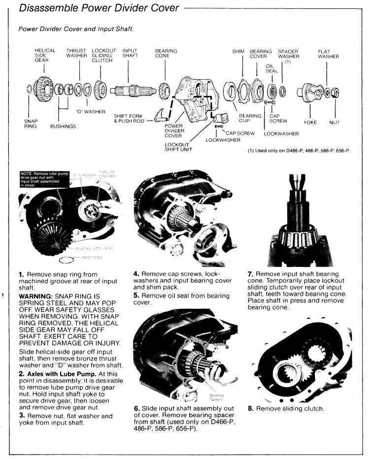
83 Power Divider Overhaul for 6x6 Tandem Axles These instructions cover the Spicer 6x6 power divider assembly and related parts. Instructions are the same for all axle gearing and models except where specified otherwise by Tandem Axle Series No. (6x6) 4-1
84 Power Divider Overhaul for 6x6 Tandem Axles 4-2 (6x6)
85 Tandem Power Divider Axle Series D346-P, 386-P, 406-P, 466-P, 486-P, 586-P, 656-P (6x6) 4-3

86 Power Divider Overhaul 4-4 (6x6)
87 (6x6) 4-5

88 Power Divider Overhaul 4-6 (6x6)
")
89 Power Divider Overhaul (6x6) 4-7
90 Power Divider Overhaul 4-8 (6x6)
")
91 Power Divider Overhaul (6x6) 4-9
92 Power Divider Overhaul 4-10 (6x6)
")
93 Power Divider Overhaul (6x6) 4-11

94 Power Divider Overhaul 4-12 (6x6)
")
95 Power Divider Overhaul (6x6) 4-13

96 Power Divider Overhaul 4-14 (6x6)
97 Differential Carriers for 6x6 Tandem Axles Single Reduction DS346-P, 386-P, 406-P, 466-P, 486-P, 586-P, 656-P These instructions cover single reduction differential carrier assemblies for 6x6 tandem forward and rear axle tandems. It is assumed that the power divider assembly has been removed from the forward axle carrier. For service information on single reduction carriers equipped with Spicer Controlled Traction Differential, refer to Section 7. (6x6) 5-1
98 6x6 Tandem Axle Single Reduction DS346-P, 386-P, 406-P, 466-P, 486-P, 586-P, 656-P 5-2 (6x6)
99 RS346, 386, 406, 466, 486, 586, 656 (6x6) 5-3

100 Differential Carrier Overhaul 5-4 (6x6)

101 Differential Carrier Overhaul (6x6) 5-5
102 Differential Carrier Overhaul 5-6 (6x6)
103 Differential Carrier Overhaul (6x6) 5-7

104 Differential Carrier Overhaul 5-8 (6x6)

105 Differential Carrier Overhaul (6x6) 5-9
106 Differential Carrier Overhaul 5-10 (6x6)

107 Differential Carrier Overhaul (6x6) 5-11

108 Differential Carrier Overhaul 5-12 (6x6)
109 Differential Carrier Overhaul (6x6) 5-13
110 Differential Carrier Overhaul 5-14 (6x6)

111 Differential Carrier Overhaul (6x6) 5-15

112 Differential Carrier Overhaul 5-16 (6x6)

113 Differential Carrier Overhaul (6x6) 5-17
114 6x6 Tandem Axle Dual Range DT346-P, 386-P, 406-P, 446-P, 486-P, 586-P, 656-P Double Reduction DP346-P, 386-P, 406-P, 446-P, 486-P, 586-P, 656-P 6-1 (6x6)
115 6x6 Tandem Axle Dual Range DT346-P, 386-P, 406-P, 446-P, 486-P, 586-P, 656-P Double Reduction DP346-P, 386-P, 406-P, 446-P, 486-P, 586-P, 656-P (6x6) 6-2
116 Differential Carrier Overhaul 6-3 (6x6)

117 Differential Carrier Overhaul (6x6) 6-4

118 Differential Carrier Overhaul 6-5 (6x6)
119 Differential Carrier Overhaul (6x6) 6-6
120 Differential Carrier Overhaul 6-7 (6x6)

121 Differential Carrier Overhaul (6x6) 6-8

122 Differential Carrier Overhaul 6-9 (6x6)

123 Differential Carrier Overhaul (6x6) 6-10

124 Differential Carrier Overhaul 6-11 (6x6)
125 Differential Carrier Overhaul (6x6) 6-12
126 Differential Carrier Overhaul 6-13 (6x6)

127 Differential Carrier Overhaul (6x6) 6-14
128 Differential Carrier Overhaul 6-15 (6x6)

129 Differential Carrier Overhaul (6x6) 6-16

130 Differential Carrier Overhaul 6-17 (6x6)

131 Differential Carrier Overhaul (6x6) 6-18
132 6-19 (6x6)
133 Service and Maintenance Instructions ESD-18 Steer-Drive Axle Spicer Axles & Brakes Contents Description and Operation Checking Effectiveness of Contreolled Traction Defferential Section 7, Page No. 2 3 CTD Overhaul All Types Remove Differential Carrier Assembly from Axle Housing Remove Differential and Clutch Pack and Carrier Medium-Duty CTD Remove and Desassemble Clutch Pack Assemble and Install Clutch Pack Medium-Duty CTD Remove and Desassemble Clutch Pack Assemble and Install Clutch Pack All Types Install Differential and Clutch Pack Assembly in Carrier Adjust Differential Bearing Preload Install Differential Carrier Assembly in Axle Housing (4x4) (6x6) 7-1
. NOTE: In this manual, instructions for both CTD design types are the same except where specified otherwise.")
134 Spicer Axle Service and Maintenance Instructions Spicer presents this publication to aid in maintenance and overhaul of Spicer single reduction axles equipped with a biasing type, controlled traction differential. In this manual, this unit is termed Controlled Traction Differential (or CTD). NOTE: In this manual, instructions for both CTD design types are the same except where specified otherwise. This manual includes specific instructions for single reduction, differential carriers (both single drive and tandem axles) equipped with Controlled Traction Differentials. For service instructions covering other axle parts and adjustments, refer to the appropriate Spicer axle service manuals. 7-2 (4x4) (6x6)
135 Spicer Controlled Traction Differen tiats (or CTD) incorporate a friction plate assembly designed to transfer torque from the slipping wheel to the one with traction. Engaged, the Spicer CTD converts to a biasing differential and assists in overcom ing adverse operating conditions. Disengaged, it restores convention al differential action for normal road conditions. The CTD unit is basically a multiple disc clutch designed to slip above predetermined torque values. This controlled slipping characteristic at higher torque values enables the vehicle to negotiate turns in a nor mal manner. Resistance to slippage at lower torque values enables the vehicle to maintain an appreciable amount of tractive effort when one wheel encounters relatively poor traction. The Controlled Traction Differential friction plate assembly (clutch pack} is under constant spring pressure. The Heavy-duty CTD clutch pack includes tanged and splined friction plates. The tanged plates, attached to the differential case, drive both axle shafts through the splined plates, thereby limiting differential action. The Medium-duty CTD clutch pack includes internal-splined and external-splined plates. The external-splined plates (engaged with internal teeth of the ring gear) drive the axle shafts through the internal-splined plates, thereby limiting differential action. In operation, the clutch pack resists spin-out and directs torque to the wheel with better traction. Operating Types The CTD is available in three operating types: 1. Driver-Controlled CTD. Engagement is controlled by a cab mounted air valve using a Spicer straight-air shift system. See Sec tion 8 for description, service and maintenance. 2. Seasonal Engagement. Manual adjustment in the shop. 3. Permanent Engagement. Constantly engaged. (4x4) (6x6) 7-3
")
136 CTD Overhaul 7-4 (4x4) (6x6)
137 7. Remove bearing cups, then lift ring gear and differential assembly out of carrier. 8. Drive Pinion: For pinion instructions. refer to appropriate Spicer Axle Service Manual covering your specific axle model. (4x4) (6x6) 7-5
138 Medium-duty CTD Overhaul 7-6 (4x4) (6x6)
139 10. Disassemble and Reassemble Wheel Differential. Refer to the appropriate Spicer Axle Service Manual covering your specific axle. (4x4) (6x6) 7-7
140 Medium-duty CTD Overhaul 7-8 (4x4) (6x6)
 7-9")
141 (4x4) (6x6) 7-9
")
142 Heavy-duty CTD Overhaul 7-10 (4x4) (6x6)
")
143 (4x4) (6x6) 7-11
")
144 Heavy-duty CTD Overhaul 7-12 (4x4) (6x6)
")
145 (4x4) (6x6) 7-13

146 CTD Overhaul NOTE: If the drive pinion was removed, refer to the appropriate Spicer Service Manual covering your specific axle for instructions (4x4) (6x6)

147 NOTE: For detailed instructions on checking and adjusting procedures, refer to the appropriate Spicer service manual covering your specific axle. (4x4) (6x6) 7-15
148 CTD Overhaul 7-16 (4x4) (6x6)
149 Service and Maintenance Instructions ESD-18 Steer-Drive Axle Spicer Axles & Brakes Contents 6x6 Drive Shift Systems Single Reduction or Double Reduction Axles Single Reduction with Controlled Traction Differentials Dual Range Axles with Range Interlock Dual Range Tandem with Single Reduction Steer-Drive Shift System Components Air Shifter Valves Standard Lockup Shift Unit Interlock Type Lockup Shift Unit Special Components Air Shift Unit(Dual Range Selection and Controlled Traction Differential) Section 7, Page No (6x6) 8-1
150 8-2 (6x6) Dual Range Axles with Range Interlock 6x6 Drive Shift Systems
151 (6x6) 8-3
152 Dual Range Axles with Range Interlock Spicer 8-4 (6x6)
153 Dual Range Axles with Range Interlock (6x6) 8-5
154 Dual Range Tandem, Single Reduction Steer-Drive 8-6 (6x6)
")
155 Dual Range Axles with Range Interlock (6x6) 8-7
156 Dual Range Axles with Range Interlock 8-8 (6x6)
157 Dual Range Tandem, Single Reduction Steer-Drive Spicer (6x6) 8-9

158 8-10 (6x6) Dual Range Tandem, Single Reduction Steer-Drive
159 Dual Range Tandem, Single Reduction Steer-Drive (6x6) 8-11

160 Dual Range Tandem, Single Reduction Steer-Drive 8-12 (6x6)
")
161 Dual Range Tandem, Single Reduction Steer-Drive (6x6) 8-13
162 Service and Maintenance Instructions ESD-18 Steer-Drive Axle Spicer Axles & Brakes These instructions include fastener tightening torque values for the steer-drive and tandem axles for 6x6 Drive Systems. Contents are listed below. Correct tightening torque values are extremely impor tant to assure long Spicer Axle life and dependable per formance. Under-tightening of attaching parts is just as harmful as over-tightening. Exact compliance with recommended torque values will assure the best results. The data includes fastener size, grade and torque tight ening values. Axle models are included to pinpoint identification of fasteners for your particular axle. To determine bolt or cap screw grade, check for designation stamped on bolt head (see illustration). 9-1 (6x6)
163 Spicer Steer-Drive Axle Steering and Wheel End Equipment Model ESD-18 Fastener Tightening Specifications (6x6) 9-2
164 Spicer Steer-Drive Axle Steering and Wheel End Equipment Model ESD-18 Fastener Tightening Specifications 9-3 (6x6)
165 (6x6) 9-4
166 9-5 (6x6)
167 (6x6) 9-6
168 9-7 (6x6)
169 (6x6) 9-8
170 9-8 (6x6)


171 Dana Aftermarket Group PO Box 321 Toledo, Ohio Warehouse Distributors: OE Dealers: AXIB-9501 Printed in U.S.A. Copyright Dana Limited, All rights reserved. Dana Limited.
172
Service Manual. Spicer Drive Axle. AXSM-0400 September 2007
 Spicer Drive Axle Service Manual Spicer Drive Axle AXSM-0400 September 2007 This bulletin contains product improvement information. Dana Corporation is not commited or liable for canvassing existing product.
Illustrated Parts List
 Spicer Tandem Drive Axles 44,000 65,000 Illustrated Parts List AXIP-0107t May 1988 For the most current information, visit the Spicer website at www.spicerparts.com Spicer Axle Parts Book Spicer presents
SUSPENSION 2-1 SUSPENSION TABLE OF CONTENTS
 DN SUSPENSION 2-1 SUSPENSION TABLE OF CONTENTS page ALIGNMENT... 1 FRONT SUSPENSION - 4x2... 6 page FRONT SUSPENSION - 4x4... 14 REAR SUSPENSION... 23 ALIGNMENT TABLE OF CONTENTS page AND OPERATION WHEEL
SUSPENSION 2-1 SUSPENSION CONTENTS
 ZJ SUSPENSION 2-1 SUSPENSION CONTENTS page ALIGNMENT... 1 FRONT SUSPENSION... 6 page REAR SUSPENSION... 14 ALIGNMENT INDEX page GENERAL INFORMATION WHEEL ALIGNMENT... 1 DIAGNOSIS AND TESTING SUSPENSION
SUSPENSION 2-1 SUSPENSION CONTENTS
 TJ SUSPENSION 2-1 SUSPENSION CONTENTS page ALIGNMENT... 1 FRONT SUSPENSION... 5 page REAR SUSPENSION... 12 ALIGNMENT INDEX page GENERAL INFORMATION WHEEL ALIGNMENT... 1 DIAGNOSIS AND TESTING SUSPENSION
SUSPENSION 2-1 SUSPENSION CONTENTS
 TJ SUSPENSION 2-1 SUSPENSION CONTENTS page ALIGNMENT... 1 FRONT SUSPENSION... 6 page REAR SUSPENSION... 13 ALIGNMENT INDEX page DESCRIPTION AND OPERATION WHEEL ALIGNMENT... 1 DIAGNOSIS AND TESTING SUSPENSION
FRONT SUSPENSION GROUP 2 FRONT SUSPENSION 2-1 CONTENTS SPECIFICATIONS VC-1, VC-2, VC-3 VY-1 TOOL LIST. Page
 GROUP 2 FRONT SUSPENSION CONTENTS Page Specifications 1 Tool List.... 1 Torque Reference 2 Preparation for Measuring Front End Alignment... 2 Front Suspension Height Adjustment 3 Front Suspension Alignment
SUSPENSION 2-1 SUSPENSION TABLE OF CONTENTS
 XJ SUSPENSION 2-1 SUSPENSION TABLE OF CONTENTS page ALIGNMENT... 1 FRONT SUSPENSION... 7 page REAR SUSPENSION... 16 ALIGNMENT TABLE OF CONTENTS page AND WHEEL ALIGNMENT...1 DIAGNOSIS AND TESTING SUSPENSION
SUSPENSION 2-1 SUSPENSION CONTENTS
 WJ SUSPENSION 2-1 SUSPENSION CONTENTS page ALIGNMENT... 1 FRONT SUSPENSION... 4 page REAR SUSPENSION... 15 ALIGNMENT INDEX page AND WHEEL ALIGNMENT... 1 SERVICE PROCEDURES PRE-ALIGNMENT... 2 AND WHEEL
SUSPENSION 2-1 SUSPENSION CONTENTS
 DN SUSPENSION 2-1 SUSPENSION CONTENTS page ALIGNMENT... 1 FRONT SUSPENSION... 5 page REAR SUSPENSION... 13 ALIGNMENT INDEX page GENERAL INFORMATION WHEEL ALIGNMENT... 1 DIAGNOSIS AND TESTING PRE-ALIGNMENT
Premium wheel-end brake products
 Premium wheel-end brake products Spicer Automatic Slack Adjuster Service Manual Self Adjusting Brake Adjuster The description and specifications contained in this service publication are current at the
Spicer Drive Axles. Service Manual. AXSM-0050 September 2007
 Spicer Drive Axles Service Manual Spicer Drive Axles AXSM-0050 September 2007 Wheel Reduction Axle Service and Maintenance Instructions Introduction Dana Corporation, Axle & Brake Division, presents this
GENERAL INFORMATION. Wheel Alignment Theory & Operation
 Fig. 1: Checking Steering Linkage GENERAL INFORMATION Wheel Alignment Theory & Operation ADJUSTMENTS NOTE: This article is intended for general information purposes only. This information may not apply
1940 Hudson SERVICING THE FRONT SUSPENSION SYSTEM
 1940 Hudson SERVICING THE FRONT SUSPENSION SYSTEM Source of this material is from 1940 Series, Issue 3, November-December Hudson Service Magazine SERVICING THE FRONT SUSPENSION SYSTEM No set rule can be
dana. Engineered for Precision. Why Dana Aftermarket Parts?
 1 Engineered for Precision. Backed by dana. Parts You Trust for the Vehicles You Rely On. Your business depends on keeping your vehicles on the road, with minimal downtime and fewer maintenance intervals.
SuperTrac. Axle. Service & Maintenance. Manual
 SuperTrac Axle Service & Maintenance Manual Table of Contents Page Exploded Views Section 1: General Information General Warnings Description of Axle Models Identifications Section 2: Installation Axle
Dana Spicer Single Drive Axles. More time on the road. Service Manual. Dana Spicer Single Drive Axles AXSM0047
 Dana Spicer Single Drive Axles More time on the road Service Manual Dana Spicer Single Drive Axles AXSM0047 September 2007 Eaton Axle Service and Maintenance Instructions Eaton R Controlled Traction Differentials
Drive Axles SHAIS171. The Dana LMS Hub is available on the following Steer and Drive Axle Models:
 Information Sheet Spicer Drive Axles SHAIS171 Topic: Dana LMS Hub Assembly Procedure Steer and Drive Axles Note: Bulletin ABIB-0302 replaces the original bulletin ABIB-9606. The Dana LMS hub design eliminates
DIAGNOSIS AND TESTING
 DIAGNOSIS AND TESTING SUSPENSION AND STEERING SYSTEM 2007 SUSPENSION Suspension - Nitro CONDITION POSSIBLE CAUSES CORRECTION FRONT END NOISE 1. Loose or worn wheel bearings. 1. Replace wheel bearings.
Illustrated Parts List
 Spicer Steer Axles Illustrated Parts List Spicer EFA Family AXIP-0074 February 2008 Table of Contents Table of Contents Introduction...2 About this Parts Book...2 Abbreviations...2 Genuine Spicer Parts...2
Camber Angle. Wheel Alignment. Camber Split. Caster Angle. Caster and Ride Height. Toe Angle. AUMT Wheel Alignment
 AUMT 1316 - Wheel Alignment 11/15/11 Camber Angle Wheel Alignment Donald Jones Brookhaven College Camber Split Camber is the amount that the centerline of the wheel tilts away from true vertical when viewed
PROPELLER SHAFTS 16-1 PROPELLER SHAFTS CONTENTS
 Z PROPELLER SHAFTS 16-1 PROPELLER SHAFTS CONTENTS page GENERAL INFORMATION... 1 PROPELLER SHAFT REPLACEMENT... 7 SERVICE DIAGNOSIS/PROCEDURES... 3 page TORQUE SPECIFICATIONS... 14 UNIVERSAL JOINT REPLACEMENT...
Illustrated Parts List
 Spicer Drive System Illustrated Parts List Spicer All Weel 6 x 6 Drive System AXIP-0600 January 1989 Axle Parts Book Corporation, Axle & Brake Division, presents this Parts Book as an aid in the identification
Ilustrated Parts List
 Spicer Drive Axles Ilustrated Parts List Spicer All Wheel 4 x 4 Drive System AXIP-0400 November 1999 Page to Insert The Spicer 4x4 Drive System Axle models and other equipment covered in this publication
Illustrated Parts List
 Spicer Drive Axles Illustrated Parts List AXIP-0487 February 201 S140 Model Table of Contents General Information... 2 How To Use Illustrated Parts List... 2 Model Identification... 3 Axle Parts Explode...
Steer Axles. Spicer. Service Manual. AXSM-0070 November Front Drive Steer Axle Model 60
 Spicer Steer Axles Service Manual AXSM-0070 November 2017 Front Drive Steer Axle Model 60 General Information The description and specifications contained in this service publication are current at the
DIFFERENTIALS & AXLE SHAFTS
 DIFFERENTIALS & AXLE SHAFTS 2001 Chevrolet Camaro 2000-01 DRIVE AXLES General Motors Differentials & Axle Shafts Chevrolet; Camaro Pontiac; Firebird DESCRIPTION & OPERATION Drive axle is a semi-floating,
FRONT SUSPENSION AND STEERING LINKAGE
 A FRONT SUSPENSION AND STEERING LINKAGE CONTENTS GROUP 2 Page LOWER BALL JOINTS 12 LOWER CONTROL ARM AND SHAFT... 9 LOWER CONTROL ARM STRUT 12 PRE-ALIGNMENT INSPECTION Height Adjustment., 4 RUBBER ISOLATED
Condensed Specifications
 Spicer Specialty Axles Condensed Specifications Spicer Specialty Axles for On/Off-Highway Specialty Applications AXSL-0010 March 1999 Cost Effective. Lighter Weight. Spicer All-Wheel Drive Systems. Fast
FRONT SUSPENSION GROUP CONTENTS GENERAL INFORMATION ON-VEHICLE SERVICE FASTENER TIGHTENING SPECIFICATIONS...
 33-1 GROUP 33 FRONT SUSPENSION CONTENTS GENERAL INFORMATION 33-2 FASTENER TIGHTENING SPECIFICATIONS 33-2 GENERAL SPECIFICATIONS 33-3 SERVICE SPECIFICATIONS 33-3 LUBRICANTS 33-3 DIAGNOSIS 33-4 INTRODUCTION
Dana Spicer Tandem Drive Axles. More time on the road. Service Manual. Dana Spicer Tandem Drive Axles AXSM0042
 Dana Spicer Tandem Drive Axles More time on the road Service Manual Dana Spicer Tandem Drive Axles AXSM0042 September 2007 Warning Warnings and Caution The description and specifications contained in this
REMOVAL & INSTALLATION
 REMOVAL & INSTALLATION AXLE SHAFTS & BEARINGS Removal CAUTION: Failure to turn off air suspension power before raising vehicle may result in unexpected inflation or deflation of air springs. DO NOT reconnect
FRONT SUSPENSION GROUP CONTENTS GENERAL INFORMATION FASTENER TIGHTENING SPECIFICATIONS GENERAL SPECIFICATIONS...
 33-1 GROUP 33 FRONT SUSPENSION CONTENTS GENERAL INFORMATION 33-2 FASTENER TIGHTENING SPECIFICATIONS 33-2 GENERAL SPECIFICATIONS 33-3 SERVICE SPECIFICATIONS 33-3 DIAGNOSIS 33-4 INTRODUCTION TO DIAGNOSIS
Section I TORSION-AIRE FRONT WHEEL SUSPENSION CONTENTS DATA AND SPECIFICATIONS MANUAL STEERING WITH POWER STEERING SPECIAL TOOLS
 CHRYSLER SERVICE MANUAL FRONT WHEEL SUSPENSION 7 Section I TORSION-AIRE FRONT WHEEL SUSPENSION CONTENTS Page Servicing the Front Wheel Suspension 10 Checking Front Suspension Height.. 12 Front Wheel Alignment
INDEX GENERAL. Page Connecting Rod 2M-3 Front Wheel Alignment 2M-4 Front Wheel Shimmy 2M-5 General 2M-1
 INDEX Page Connecting Rod 2M-3 Front Wheel Alignment 2M-4 Front Wheel Shimmy 2M-5 General 2M-1 Pago Specifications 21-8 Steering Damper 2M-3 Steering Wheel Spoke Alignment 2M-5 Tie Rod 2M-3 GENERAL The
Spicer Tandem Drive Axles. Service Manual. AXSM-0045 September 2007
 Spicer Tandem Drive Axles Service Manual Spicer Tandem Drive Axles AXSM-0045 September 2007 Spicer Axle Service and Maintenance Instructions Tandem Drive Axles Dual Range and Planetary Double Reduction
Independent Front Suspension
 Independent Front Suspension Technical Training Contents Why Independent? Tuthill Models Features and Benefits Description Special Tools Regular Maintenance Troubleshooting Available Kits Contacting Tuthill
FRONT SUSPENSION GROUP CONTENTS GENERAL INFORMATION SPECIFICATIONS STRUT ASSEMBLY FRONT SUSPENSION DIAGNOSIS.
 33-1 GROUP 33 FRONT SUSPENSION CONTENTS GENERAL INFORMATION 33-2 SPECIFICATIONS 33-3 FASTENER TIGHTENING SPECIFICATIONS 33-3 GENERAL SPECIFICATIONS 33-3 SERVICE SPECIFICATIONS 33-3 LUBRICANT 33-3 DIAGNOSIS
FRONT AXLE - 9 1/4 AA
 DR FRONT AXLE - 9 1/4 AA 3-45 FRONT AXLE - 9 1/4 AA TABLE OF CONTENTS page FRONT AXLE - 9 1/4 AA DESCRIPTION......................... 45 OPERATION........................... 45 DIAGNOSIS AND TESTING................
2004 SUSPENSION. Wheel Alignment - Corvette. Caster Cross +/ / Fastener Tightening Specifications Specification Application
 2004 SUSPENSION Wheel Alignment - Corvette SPECIFICATIONS WHEEL ALIGNMENT SPECIFICATIONS Wheel Alignment Specifications Camber Cross Caster Cross Suspension Camber Tolerance Caster Tolerance FE1 & FE3
STEERING SYSTEM Introduction
 STEERING SYSTEM Introduction The steering makes it possible to change direction. The steering must be reliable and safe; there must not be too much play in the steering. It must be possible to steer accurately.
SECTION Front Drive Axle/Differential
 205-03-i Front Drive Axle/Differential 205-03-i SECTION 205-03 Front Drive Axle/Differential CONTENTS PAGE Axle... 205-03-2 205-03-2 Front Drive Axle/Differential 205-03-2 Axle Special Tool(s) C-Frame
REAR SUSPENSION GROUP CONTENTS GENERAL DESCRIPTION REAR SUSPENSION DIAGNOSIS LOWER ARM AND TOE CONTROL ARM ASSEMBLY...
 34-1 GROUP 34 CONTENTS GENERAL DESCRIPTION........... 34-2 DIAGNOSIS.... 34-2 INTRODUCTION....................... 34-2 TROUBLESHOOTING STRATEGY........ 34-2 SYMPTOM CHART..................... 34-3 SYMPTOM
SECTION ZF FRONT AXLE
 04-101.01/ 1 2011JA14 SECTION 04-101.01 6 3 5 1 2 9 1. Upper radius rod 2. Lower radius rod 3. Caliper 4. BRAKE Disk 5. Pneumatic connector 6. Hub 7. steering knuckle 8. Grease Fitting 9. Pneumatic connector
1984 Dodge W250 PICKUP
 1984 Dodge W250 PICKUP Submodel: Engine Type: V8 Liters: 5.2 Fuel Delivery: CARB Fuel: GAS Dana 44 MODELS THROUGH 1984 2. Raise and safely support the vehicle, then remove the wheel hub and bearings as
TIRES AND WHEELS 22-1 TIRES AND WHEELS CONTENTS
 ZJ TIRES AND WHEELS 22-1 TIRES AND WHEELS CONTENTS TIRES... 1 WHEELS... 7 TIRES INDEX DESCRIPTION AND OPERATION RADIAL-PLY TIRES... 2 REPLACEMENT TIRES... 3 SPARE TIRE TEMPORARY... 2 TIRE INFLATION PRESSURES...
Wheels. Wheels and Tires ! CAUTION. Wheel Selection
 Wheels Wheel Selection Wheels are a very important and critical component of your running gear system. When specifying or replacing your trailer wheels it is important that the wheels, tires, and axle
BRAKES. Section III REAR AXLE DATA AND SPECIFICATIONS HAND BRAKE CHRYSLER SERVICE MANUAL BRAKES 17
 BRAKES 17 There is no basic design change in the rear axle and sure grip differential except the larger diameter pinion shaft is now used on all models for 1959. The Service Procedures will remain the
DRIVE AXLE Volvo 960 DESCRIPTION & OPERATION AXLE IDENTIFICATION DRIVE AXLES Volvo Differentials & Axle Shafts
 DRIVE AXLE 1994 Volvo 960 1994 DRIVE AXLES Volvo Differentials & Axle Shafts 960 DESCRIPTION & OPERATION All 960 station wagon models use type 1041 rear axle assembly. All 960 4-door models use type 1045
Wheels. Wheels and Tires ! CAUTION. Wheel Selection
 Wheel Selection Wheels Wheels are very important and critical components of your running gear system. When specifying or replacing your trailer wheels it is important that the wheels, tires, and axle are
SUSPENSION SYSTEM PROBLEM SYMPTOMS TABLE SP 1
 SUENSION SUENSION SYSTEM 1 Vehicle/pulls Bottoming Sway/pitches Wheel shimmy Abnormal tire wear SUENSION SYSTEM PROBLEM SYMPTOMS TABLE Use the table below to help determine the cause of the problem. The
MANUAL TRANSAXLE Return to Main Table of Contents
 MANUAL TRANSAXLE Return to Main Table of Contents GENERAL... 2 MANUAL TRANSAXLE CONTROL... 12 SHIFT LEVER ASSEMBLY... 14 MANUAL TRANSAXLE... 15 MANUAL TRANSAXLE ASSEMBLY... 17 FIFTH SPEED SYNCHRONIZER
Dana Spicer Single Drive Axles. More time on the road. Service Manual. Dana Spicer Single Drive Axles AXSM0041
 Dana Spicer Single Drive Axles More time on the road Service Manual Dana Spicer Single Drive Axles AXSM0041 September 2007 Table of Contents Introduction...1 Failure Analysis...7 Inspection...9 Differential
REAR SUSPENSION GROUP CONTENTS GENERAL DESCRIPTION TRAILING ARM ASSEMBLY REAR SUSPENSION DIAGNOSIS
 34-1 GROUP 34 CONTENTS GENERAL DESCRIPTION......... 34-2 DIAGNOSIS.. 34-3 INTRODUCTION TO DIAGNOSIS........................ 34-3 DIAGNOSIS TROUBLESHOOTING STRATEGY...... 34-3 SYMPTOM CHART...................
WHEELS BEARINGS TIRES
 GROUP 22 WHEELS BEARINGS TIRES CONTENTS Page GENERAL INFORMATION 1 SERVICE DIAGNOSIS 1 SERVICE PROCEDURES... 2 WHEELS... 2 Page BEARINGS 2 TIRES 4 SPECIFICATIONS AND TIGHTENING REFERENCE.. In Rear of Manual
 Page 1 of 8 SECTION 204-00: Suspension System - General Information 1998 Contour/Mystique Workshop Manual DIAGNOSIS AND TESTING Procedure revision date: 09/14/2001 Suspension System Special Tool(s) Dial
FRONT AXLE GROUP 11A CONTENTS 11A-0. SECTION 0 GENERAL Removal 3 SECTION 1 FRONT AXLE HUB 1
 11A-0 GROUP 11A FRONT AXLE CONTENTS SECTION 0 GENERAL 1 1-1 Removal 3 SECTION 1 FRONT AXLE HUB 1 1-2 Inspection 3 1-3 Installation 4 1. Removal and Installation 1 1-1 Removal 1 SECTION 3 WHEEL ALIGNMENT
SECTION 17 SUSPENSION CONTENTS FRONT SUSPENSION REAR SUSPENSION MAINTENANCE SERVICES
 SECTION 17 SUSPENSION CONTENTS 17-1. FRONT SUSPENSION...................................... 17-2 17-2. REAR SUSPENSION...................................... 17-15 17-3. MAINTENANCE SERVICES................................
Typical mounting of a dial indicator for a radial check. Moog Automotive, Inc.
 Inspect / Service / Test / Replace To find out if the ball joint is loose beyond manufacturer's specifications, use an accurate measuring device. Most load carrying ball joints have a wear limit of 0.060"
Suspension System RS6582B
 Suspension System RS6582B Tahoe/Yukon READ ALL INSTRUCTIONS THOROUGHLY FROM START TO FINISH BEFORE BEGINNING INSTALLATION IMPORTANT NOTES! WARNING: This suspension system will enhance the off-road performance
Why do cars need Alignment
 Why do cars need Alignment The main purpose of wheel alignment is to make the tires roll without Scuffing, slipping, or dragging under all operating conditions. Caster Camber Toe Steering axis inclination
Inspection and Verification, Ranger
 file://c:\tso\tsocache\vdtom_5368\svk~us~en~file=svk53a03.htm~gen~ref.htm Page 1 of 1 Section 05-03A: Wheel Hubs and Bearings, Front Wheels, 4- Wheel Drive DIAGNOSIS AND TESTING 1997 Ranger 4x4 with Dana
TC Series Front Axle. TC Series Front Axle 010-1
 TC Series Front Axle Blue Bird Corporation assumes sole responsibility for ensuring that the information provided herein is accurate to the best of its knowledge at the time of printing. In keeping with
STERNDRIVE UNIT 3 A DRIVE SHAFT HOUSING
 STERNDRIVE UNIT 3 A 23262 DRIVE SHAFT HOUSING Table of Contents Page Specifications............................ 3A-1 Torque Specifications.................. 3A-1 Upper Drive Shaft Bearing Preload.......
2011 MKS Workshop Manual. SECTION : Suspension System - General Information DESCRIPTION AND OPERATION Procedure revision date: 05/25/2010
 SECTION 204-00: Suspension System - General Information 2011 MKS Workshop Manual DESCRIPTION AND OPERATION Procedure revision date: 05/25/2010 Wheel Alignment Angles Camber Negative and Positive Camber
M Ring and Pinion Installation
 !!! PLEASE READ ALL OF THE FOLLOWING INSTRUCTIONS CAREFULLY PRIOR TO INSTALLATION. Axle Shaft Removal (1994-2012 Mustang typical) STEP 1: STEP 2: Remove the 10 differential housing cover bolts and drain
FRONT SUSPENSION GROUP 33A 33A-1 CONTENTS GENERAL DESCRIPTION... 33A-2 FRONT SUSPENSION DIAGNOSIS. 33A-3 LOWER ARM... 33A-13 SPECIAL TOOLS...
 33A-1 GROUP 33A FRONT SUSPENSION CONTENTS GENERAL DESCRIPTION......... 33A-2 DIAGNOSIS. 33A-3 INTRODUCTION TO DIAGNOSIS........................ 33A-3 DIAGNOSIS TROUBLESHOOTING STRATEGY...... 33A-3 SYMPTOM
FRONT & REAR SUSPENSION SECTIONSU CONTENTS IDX. FRONT SUSPENSION...2 Precautions...2. REAR SUSPENSION...14 Precautions...14
 FRONT & REAR SUSPENSION SECTIONSU GI MA EM LC EC CONTENTS FE FRONT SUSPENSION...2 Precautions...2 PRECAUTIONS...2 Preparation...2 SPECIAL SERVICE TOOLS...2 COMMERCIAL SERVICE TOOLS...2 Noise, Vibration
S-ABA Service Manual. Self-Setting Automatic Brake Adjusters
 S-ABA Service Manual Self-Setting Automatic Brake Adjusters Warning: Haldex strongly recommends routine visual checks be performed at EACH maintenance service interval. Foundation brake operational checks
Refer to separate Installation Instructions for installation details.
 OWNER S GUIDE 8A000729 DuraLift 13.5 13,500 CAPACITY Link Mfg. Ltd. 223 15th St. N.E. Sioux Center, IA USA 51250-2120 www.linkmfg.com QUESTIONS? CALL CUSTOMER SERVICE 1-800-222-6283 DEALER / INSTALLER:
1988 Chevrolet Pickup V SUSPENSION - FRONT (4WD)' 'Front Suspension - "V" Series 1988 SUSPENSION - FRONT (4WD) Front Suspension - "V" Series
' 'Front Suspension - V Series 1988 SUSPENSION - FRONT (4WD) Front Suspension - V Series") 1988 SUSPENSION - FRONT (4WD) Front Suspension - "V" Series DESCRIPTION NOTE: Vehicle serial numbers used in this article has been abbreviated for common reference to Chevrolet and GMC models. Chevrolet
1988 SUSPENSION - FRONT (4WD) Front Suspension - "V" Series DESCRIPTION NOTE: Vehicle serial numbers used in this article has been abbreviated for common reference to Chevrolet and GMC models. Chevrolet
Basic Wheel Alignment Techniques
 Basic Wheel Alignment Techniques MASTERING THE BASICS: Modern steering and suspension systems are great examples of solid geometry at work. Wheel alignment integrates all the factors of steering and suspension
SECTION 3D REAR AXLE TABLE OF CONTENTS
 SECTION 3D REAR AXLE TABLE OF CONTENTS General Description and Operation... 3D-2 Specifications... 3D-2 Fastener Tightening Specifications... 3D-2 Diagnostic Information and Procedures... 3D-3 Component
Illustrated Parts List
 Spicer Drive Axles Illustrated Parts List AXIP-00322 February 2015 Two-Speed-Planetary Double Reduction 19055T/P, 21065T/P, 22065T/P, 23065T/P Model Table of Contents General Information... 3 How To Use
Spicer Tandem Drive Axles. Service Manual. AXSM0057 September D170 Series D190 Series D590 Series
 Spicer Tandem Drive Axles Service Manual AXSM0057 September 03 D70 Series D90 Series D590 Series General Information General Information The description and specifications contained in this service publication
INSTALLATION INSTRUCTION 88088
 INSTALLATION INSTRUCTION 88088 For Rancho Suspension Systems RS6588 & RS6589: FORD F-150 READ ALL INSTRUCTIONS THOROUGHLY FROM START TO FINISH BEFORE BEGINNING INSTALLATION Rev B IMPORTANT NOTES! WARNING:
Return To Main Table of Contents GENERAL... 2 STRUT ASSEMBLY LOWER ARM STABILIZER BAR CENTER MEMBER WHEEL AND TIRE...
 FRONT SUSPENSION Return To Main Table of Contents GENERAL... 2 STRUT ASSEMBLY... 11 LOWER ARM... 13 STABILIZER BAR... 17 CENTER MEMBER... 19 WHEEL AND TIRE... 21 GENERAL GENERAL SPECIFICATIONS Suspension
FRONT & REAR SUSPENSION SECTIONSU CONTENTS IDX. FRONT SUSPENSION...2 Precautions...2
 FRONT & REAR SUSPENSION SECTIONSU GI MA EM LC EC CONTENTS FE...2 Precautions...2 PRECAUTIONS...2 Preparation...2 SPECIAL SERVICE TOOLS...2 COMMERCIAL SERVICE TOOLS...2 Noise, Vibration and Harshness (NVH)
Diagnostic Procedures
 Section 6 Diagnostic Procedures Learning Objectives: 1. Describe manual transmission, transaxle and transfer case component inspection and diagnostic procedures 2. Identify clutch component inspection
HUB & WHEEL INSTALLATION
 HUB & WHEEL INSTALLATION 1.0 SCOPE This specification covers the torque requirements for the attachment of all component parts of Spoke Wheels, Rims, Tyres and Hub assemblies. 1.1 Spoke Wheels CAUTION:
GROUP 33A 33A-1 CONTENTS GENERAL DESCRIPTION... 33A-2 FRONT SUSPENSION DIAGNOSIS. 33A-3 LOWER ARM... 33A-13 SPECIAL TOOLS... 33A-5
 33A-1 GROUP 33A CONTENTS GENERAL DESCRIPTION 33A-2 DIAGNOSIS 33A-3 INTRODUCTION TO FRONT SUSPENSION DIAGNOSIS 33A-3 DIAGNOSIS TROUBLESHOOTING STRATEGY 33A-3 SYMPTOM CHART 33A-3 SYMPTOM PROCEDURES 33A-3
Spicer Tandem Axles. List
 Spicer Tandem Axles Illustrated Parts List Spicer S400- S Tandem Rear Axle AXIP-1951 September 2013 (Supersedes February 2002) TableofContents Table of Contents Introduction How To Use Illustrated Parts
SECTION 3A FRONT DRIVE AXLE TABLE OF CONTENTS SPECIFICATIONS GENERAL SPECIFICATIONS. Description Drive Shaft Type. CV Joint Axle Housing Type
 SECTION 3A FRONT DRIVE AXLE TABLE OF CONTENTS Specifications........................ 3A-1 General Specifications.................. 3A-1 Fastener Tightening Specifications......... 3A-2 Component Locator...................
FRONT SUSPENSION SECTION CONTENTS E SUSPENSION FSU-1 FSU
 E SUSPENSION A SECTION FRONT SUSPENSION B C D CONTENTS FSU PRECAUTIONS... 2 Precautions... 2 PREPARATION... 3 Special Service Tools... 3 Commercial Service Tools... 3 NOISE, VIBRATION, AND HARSHNESS (NVH)
DISASSEMBLY AND ASSEMBLY
 205-03-1 Front Drive Axle/Differential Ford 8.8-Inch Ring Gear 205-03-1 DISASSEMBLY AND ASSEMBLY Axle Front Drive Special Tool(s) 2-Jaw Puller 205-D072 (D97L-4221-A) Special Tool(s) Carrier Bearing Replacer
Technician Handbook. 453 Suspension, Steering and Handling. Technician Objectives
 Technician Objectives 1. List the six functions of suspension components.. 2. List the six major groups of components that require inspection. 3. Explain the inspection methods for the individual suspension
SUSPENSION SYSTEM PROBLEM SYMPTOMS TABLE SP 1
 SUENSION SUENSION SYSTEM 1 SUENSION SYSTEM Suspension system Vehicle is unstable Bottoming Sways/pitches Wheels shimmy Abnormal tire wear Vehice pull PROBLEM SYMPTOMS TABLE Use the table below to help
CHASSIS CONTENTS FRONT WHEEL 6-1 FRONT BRAKE 6-6 FRONT FORK 6-14 STEERING STEM 6-20 REAR WHEEL AND REAR BRAKE 6-25 SUSPENSION 6-31 REAR SWING ARM 6-36
 CHASSIS CONTENTS FRONT WHEEL 6-1 FRONT BRAKE 6-6 FRONT FORK 6-14 STEERING STEM 6-20 REAR WHEEL AND REAR BRAKE 6-25 SUSPENSION 6-31 REAR SWING ARM 6-36 6 6-1 CHASSIS FRONT WHEEL REMOVAL Support the machine
Illustrated Parts List
 Spicer Drive Axles Illustrated Parts List AXIP-0055 May 2014 S130, S132 Model Table of Contents Table of Contents General Information...2 How To Use Illustrated Parts List...2 Model Identification...3
Premium wheel-end brake products. Supplement to BW7253
 Premium wheel-end brake products Bendix ESD-225 Air Disc Brake Supplement to BW7253 I l l u s t r a t e d P a r t s L i s t Table of Contents Table of Contents Introduction About this Parts Book...2 Abbreviations...2
Module 6: Air Foundation Brakes
 Air Brakes Terms and Definitions Basic Components That Make Up Air Foundation Brakes Types of Air Foundation Brakes Parts of a Cam Foundation Brake Parts of a Wedge Foundation Brake Parts of a Disc Foundation
POWER STEERING TO INDEX POWER STEERING SYSTEM PRECAUTIONS... OPERATION CHECK... PROBLEM SYMPTOMS TABLE... VANE PUMP ASSEMBLY COMPONENTS...
 TO INDEX STEERING POWER STEERING POWER STEERING SYSTEM PRECAUTIONS.............................................. OPERATION CHECK......................................... PROBLEM SYMPTOMS TABLE.................................
OPERATION AND MAINTENANCE MANUAL
 WREN IBT SERIES HYDRAULIC TORQUE WRENCHES IBT SQUARE DRIVE SERIES OPERATION AND MAINTENANCE MANUAL FOR WREN Products: POINT 75, 1IBT, 3IBT, 5IBT, 8IBT, 10IBT, 20IBT, 25IBT, 35IBT, 50IBT SQUARE DRIVE HYDRAULIC
SPECIAL TOOLS Dodge Pickup 5.9L Eng R3500. Fig 1: Identifying Remover C-3985-B (Special Tool) 9/6/13 Printer Friendly View
 9/6/13 Printer Friendly View") Procedures 2003 Dodge Pickup 5.9L Eng R3500 manual transmission SPECIAL TOOLS Fig 1: Identifying Remover C-3985-B (Special Tool) www2.prodemand.com/print/index?content=tabs&module=true&tab=true&terms=true&ymms=false&classname=
Procedures 2003 Dodge Pickup 5.9L Eng R3500 manual transmission SPECIAL TOOLS Fig 1: Identifying Remover C-3985-B (Special Tool) www2.prodemand.com/print/index?content=tabs&module=true&tab=true&terms=true&ymms=false&classname=
TECHNICAL BULLETIN. TP Issued Servicing Rockwell s TB Series Trailer Axles with Unitized Hub Assemblies
 TECHNICAL BULLETIN TP-96175 Issued 12-96 Servicing Rockwell s TB Series Trailer Axles with Unitized Hub Assemblies TB Series Trailer Axles Introduction Rockwell s TB series trailer axle features a permanently
SECTION 4A HYDRAULIC BRAKES
 SECTION 4A HYDRAULIC BRAKES CAUTION: Disconnect the negative battery cable before removing or installing any electrical unit or when a tool or equipment could easily come in contact with exposed electrical
(800) MON-FRI 7AM-5PM PST OR WEBSITE: ReadyLIFT.COM **Please retain this document in your vehicle at all times**
 MON-FRI 7AM-5PM PST OR WEBSITE: ReadyLIFT.COM **Please retain this document in your vehicle at all times**") IF YOUR ReadyLIFT PRODUCT IS MISSING A OR HAS A DAM- AGED PART, PLEASE CONTACT CUSTOMER SERVICE DIRECTLY. For warranty issues please return to the place of installation and contact ReadyLIFT. A NEW REPLACEMENT
IF YOUR ReadyLIFT PRODUCT IS MISSING A OR HAS A DAM- AGED PART, PLEASE CONTACT CUSTOMER SERVICE DIRECTLY. For warranty issues please return to the place of installation and contact ReadyLIFT. A NEW REPLACEMENT
SECTION 3A WHEEL ALIGNMENT
 SECTION 3A WHEEL ALIGNMENT NOTICE: All wheel alignment fasteners are important attaching parts in that they could affect the performance of vital components and systems, and/or could result in major repair
151 Lawrence Drive, Livermore, CA Phone: (925) Fax: (925)
 Fax: (925)") 151 Lawrence Drive, Livermore, CA 94551 Phone: (925) 454-9500 Fax: (925) 454-9501 www.fabcoautomotive.com TABLE OF CONTENTS I. DESCRIPTION AND OPERATION A. General Description B. Operation C. Operating
151 Lawrence Drive, Livermore, CA 94551 Phone: (925) 454-9500 Fax: (925) 454-9501 www.fabcoautomotive.com TABLE OF CONTENTS I. DESCRIPTION AND OPERATION A. General Description B. Operation C. Operating
FSD-18A, 21A, & 23A STEERABLE DRIVE AXLE SERVICE MANUAL ()
") FSD-18A, 21A, & 23A STEERABLE DRIVE AXLE SERVICE MANUAL 625-0518() TABLE OF CONTENTS INTRODUCTION...... 1.0 General Description.......1.1 Operation.........1.2 Operating Instructions...... 1.3 Specifications..............1.4
FSD-18A, 21A, & 23A STEERABLE DRIVE AXLE SERVICE MANUAL 625-0518() TABLE OF CONTENTS INTRODUCTION...... 1.0 General Description.......1.1 Operation.........1.2 Operating Instructions...... 1.3 Specifications..............1.4