LIVESTOCK TRAILER OWNER S MANUAL
|
|
|
- Gregory Riley
- 5 years ago
- Views:
Transcription

1 Wilson Trailer Company LIVESTOCK TRAILER OWNER S MANUAL This manual has been prepared to help you operate your new Wilson trailer successfully, economically, and safely. Should you have any questions, we ask that you contact a Wilson Trailer Company factory representative immediately for a clear explanation. We thank you for expressing your confidence in us through the purchase of your new Wilson Livestock trailer. We want you to know that it was designed to meet your specific needs for a livestock trailer and was built for long life and low cost operation. With regular, proper maintenance and your common sense use, we are confident that it will do so. Additional owner s manuals and decal kits for this trailer are available without charge. (Rev.6-99) This Manual Includes: Certificate of Limited Warranty Disclaimer and Exclusive Remedies to Which the Sale is Subject. MODEL NO. SERIAL NO.
2 This safety alert symbol is to raise your awareness to important messages in this manual. When you see this symbol, be alert to the possibility of personal injury and carefully read the message that follows. TABLE OF CONTENTS by SECTION GENERAL INFORMATION Normal Trailer Operation Loading and Unloading of Livestock Modification of Trailer SAFETY Decals and Emblems Federal Motor Vehicle Safety Standard Rear Impact Guards ABS Braking System Backup Warning System Over-the-Road Safe Handling Wheel Torques Inspection Procedure Before Trip Brake and Electrical Controls Fifth Wheel and King Pin Engagement Door Locks Tires Wide Base Single Tires & 2 Offset Wheels Hub Lubricants Hub Maintenance Wheels and Rims Disc Wheel Installation Wheel Nut Torques Mud Flaps Gates Lift Deck Slider - Suspension Air Ride - Suspension Spring - Suspension Side Structure Operating Instructions Parking/Emergency Braking Loading and Unloading Landing Leg Use Front Counter-Balanced Gate Rear Compartment Dog House Suspension - Sliding Repositioning Slider Suspension - Air Ride Liftbable Suspension Axle Auto Lower System Liftable, Regulated Axle (Dial Down) Parking and Dock Walk Liftable Suspension Tire Changing Procedure Backing Operation of Nose Carrier Storing the Tire Removing the Spare Tire King Pin and Fifth Wheel Lube Plates Hubs and Bearings Axilok Installation Procedures Spindle Nut & Wheel Bearing Adustment Wheel Bearing Inspection Bearing Lubricant Brakes Spring Brake In-Service Checking Procedures Automatic Slack Adjusters Disc Wheel and Tire Assembly Mounting Instructions Air System Cold Weather Operation Thawing Frozen Air Lines Reservoir Draining Air Travels through Brake Valves Proper Axle Alignment Full Air Ride Suspension Spring Suspension Holland SwingAlign Axle Alignment Neway EZ-Align Suspension Hendrickson Quik-Align Suspension Electical System Connector Wiring Diagram Wiring Diagram Harness Diagram Electrical Troubleshooting ABS Valve Cap Securement Pneumatic System Spring ABS Pneumatics Air Ride ABS Pneumatics Load Sensing Axle System (LSAS) Pull Trailer Dolly Connections General Maintenance Misc Floor Gate and Ramp Hinges Fastenings Washout Notice King Pin Inspection and Maintenance CONSUMER INFORMATION Reporting Safety Defects Keep Informed Customer Assistance Certificate of Limited Warranty Extended Warranty Schedule INDEX Index...6-1
3 Normal Trailer Operation NOTICE The maximum load indicated on the identification plate may not be a legal load on the highway you plan to use. States have differing laws and regulations affecting vehicle lengths and weights on roads that are not a part of the primary interstate road system. This Wilson trailer is designed for operation within legal highway speed limits on reasonable road surfaces for the type of service it was built to perform, in accordance with the noted weight restrictions. Normal use means the loading, unloading and transportation of uniformly distributed legal loads, in a manner which does not subject the trailer to stresses or impacts greater than imposed by reasonable use. This trailer was built to carry cargo within the two weight ratings on the identification plate located on the road side of the trailer near the front. The GAWR (gross axle weight rating) is the structural capability of the lowest rated member of the running gear component: suspension and spring system, hub, wheels and drums, rims, bearings, brakes, axles, or tires. The GVWR (gross vehicle weight rating) is the structural capability of the trailer when supported by the kingpin and axles with the load uniformly distributed throughout the cargo space. Loading and Transport of Livestock The loading of the trailer is important! Keep the center of gravity as low as possible. Proper placement of the larger animals should be considered. Because load types vary, the driver needs to drive with appropriate care and within the limits of the load. The well being of the livestock is dependent on the stock density, ventilation, the standard of driving, and quality of roads. Frequent inspection and careful driving cannot be overemphasized! Modification of Trailer Any modification made to the trailer must comply with DOT and NHTSA regulations and must not compromise the gross vehicle weight rating (GVWR) of the trailer. (Rev ) WARNING Any operation of the trailer outside the limitations stated in this manual will void any responsibility of Wilson Trailer Company for any of its results. General Information 1-1


4 SAFETY CAUTION Personal Injury, death, and property damage may result from improper operation or unsafe practices. Be sure to read and follow all decals and emblems carefully. Decals and Emblems ACC A The following section contains the decals and emblems used on Wilson Livestock Trailers. Due to differences in configurations and equipment, your trailer may or may not use all the decals and emblems listed. Newer trailers may also have decals and emblems that differ from older trailers. Replace damaged or missing decals promptly. ACC A AAA AAA AAA LQ AAA AK AAA AW ABB ABB A AAA DX ABB C AAA EH AAA GP AAA DW AAA DG AAA CZ (Rev ) 2-1 Safety


5 SAFETY Decals and Emblems AAA P AAA BF AAA AH AAA BJ AAA AQ AAA BL AAA AW AAA K AAA DH AAA P AAA Q AAA GC AAA C AAA GT AAA DR AAA GB AAA MA AAA AS (Rev ) Safety 2-2
6 SAFETY Federal Motor Vehicle Safety Standard 121 Your new Wilson trailer is equipped with an air brake system which will meet or exceed the requirements set forth in this federal regulation. Mandatory 10/8/92 FMVSS-121 requires that the supply line be protected to 70 psi. Previously, pressure was near the 55 psi level. The higher pressure protection levels require that supply line pressure levels be achieved before the pressure protection valve opens (opening pressures must be higher than closing pressures by design). Keeping your compressor cut-in pressure at maximum levels (over 100 psi) is a clear advantage for peak operation of your entire system; we recommend using a 105 psi cut-in governor. Air leaks at spring brake chambers, reservoir fittings, drain valves, drop hoses, and connections can cause the air system to perform less efficiently and the compressor to cycle too frequently. If you suspect air system problems in either service brakes or spring brakes, don't hesitate: - Use the "soap bubble" test at all connections throughout the air system to detect external leaks. - Check for exhaust leaks at all valves to detect internal leaks. - Check the actuator and spring brake push rod for proper movement in operational modes. Should you still have a problem after going through the listed tests, contact your vehicle manufacturer's service representative. (Rev. 6-01) 2-3 Safety
 has been installed on your trailer with rear tires 12 inches or more from the rear of the trailer. Trailer R.I.G.'s are subject to impacts and stress in docking and loading operations.")

7 SAFETY Rear Impact Guards Effective January 26, 1998, all trailers must conform to FMVSS 223 and 224, which specify equipment and performance standards for rear impact guards on new semi-trailers. A R.I.G. (rear impact guard) has been installed on your trailer with rear tires 12 inches or more from the rear of the trailer. Trailer R.I.G.'s are subject to impacts and stress in docking and loading operations. A damaged guard may not be as strong as originally manufactured and may not satisfy NHTSA performance standards. Pre-trip inspections should be made of the guard to assure its integrity and strength. Broken welds, bent components, missing or loose fasteners, or other damage will likely affect its performance. For these reasons, R.I.G. inspection, service, and repair records should be maintained. Repairs and replacements must be in accordance with the original design specifications of the guard. In the event that a Wilson trailer is impacted by another vehicle in a rear-end collision photgraphs should be taken before any repairs is made. Any questions regarding repair or replacement can be directed to your Wilson representative. (Rev ) ABS Braking System All trailers manufactured with air braking systems are required to have ABS (Anti-Lock Braking System). The systems used on your livestock trailer meet or exceed the FMVSS-121 requirement for ABS. The ABS system, specified a Midland Grau, Rockwell, or Bendix, as a minimum for livestock trailers is a 4S/2M (4 sensor-2 modulator) system. The intended purpose of ABS is to help maintain control and reduce the likelihood of jackknife situations. The ABS indicator light is located at the drivers side rear of the trailer (effective ). The lighting sequence is "on"-"off" upon initial startup. If a malfunction occurs, the light will come on and stay on until the problem is fixed. NOTICE ABS (Anti-Lock Braking Systems) is a safety item and must be properly maintained. To operate an ABS equipped truck and trailer properly, during braking - constant pedal force must be applied. (Rev. 2-98) Safety 2-4
 (Rev. 9-03) The backup warning system is intended to indicate that the vehicle is backing up.")
8 SAFETY Backup Warning System A backup warning system consisting of rear facing white lights and an audible alarm is available as an option on Wilson trailers. (Livestock trailers are not equipped with an audible alarm.) (Rev. 9-03) The backup warning system is intended to indicate that the vehicle is backing up. Separate backup or spotlight options are available for illuminating the area behind the trailer. The system is activated by rearward movement and will turn "ON" after a short distance has been traveled in the reverse direction and will turn "OFF" when the trailer stops moving backward or moves any distance forward. The backup warning system draws power from the auxiliary (blue) circuit of the trailer's main electrical harness. The auxiliary circuit must be constantly powered from the tractor for the backup warning system to operate. Travel direction is determined by a sensor installed on the rearmost wheel end on the driver's (road) side of the trailer. Proper orientation of this sensor and the correct distance from the toner ring is critical for proper system operation. If the backup warning system fails to operate properly: 1. Be sure the auxiliary (blue) circuit is powered continuously by the tractor. 2. Check cable connections to the sensor, main harness drop-off, control box, lights, and alarm. 3. Check the orientation of the backup warning sensor. The mark on the top of the sensor must be directly away from the axle within to function properly. If, after checking these items, the system still does not function properly, contact Wilson Trailer Service Department for assistance. (Rev. 4-01) 2-5 Safety
9 SAFETY Over-The-Road Safe Handling YOU AND YOUR SAFETY 1. You - the OPERATOR - have control of the most important factors that affect vehicle stability. Trailers are important tools in our transportation industry and, like any tool, are safe in the hands of a properly qualified operator. 2. The fifth wheel should be securely mounted to the tractor frame. 3. The driver should be familiar with the characteristics of the particular trailer and the load being transported. 4. The driver should be familiar with the nature of the roads and traffic which may be encountered during the trip. 5. Stability CAUTION Like any other vehicles, semi-trailers can tip or slide out of control if turns are negotiated at too high a speed or when making violent maneuvers such as abrupt lane changes or other evasive actions to avoid obstacles. 6. Within the relatively narrow confines of road laws limiting vehicle size and weight, together with the characteristics of available tires, suspensions, and other components, there is little that a manufacturer can do to affect the inherent stability of a trailer other than keeping the loading decks as low as feasible, considering the requirements for loading space and adequate tire clearance. This means that the major factors affecting operational stability are the knowledge and skill of the driver. The predominant causes of the rollover accidents are: Excessive speed. Violent swerving or turning. Application of brakes or tractor power while turning. Safety 2-6
10 SAFETY Over-The-Road Safe Handling Entering curves at too high a speed may be caused by one of the following factors: a. Traveling at freeway speeds for long periods of time and failing to recognize the high speed of travel and reducing it before entering freeway interchanges or other curves requiring a reduced and controlled speed. b. Lack of familiarity with the vehicle characteristics to recognize its safe speed with relation to posted speed limits on curves, which are usually determined with automobile traffic in mind. c. Failure to reduce speed sufficiently when approaching congested traffic such as might be found at traffic signals on highways. With the advent of today s more powerful and higher torque engines, the original practice of maintaining momentum to avoid acceleration in traffic is outmoded. 7. Tire Characteristics: High pressure truck/trailer tires have different characteristics under high speed cornering conditions than do passenger car tires. As an extreme example, it is fairly common knowledge that a skilled race car driver can consistently drift his racer around tight turns where very high lateral g forces are encountered. However, truck/trailer tires which are designed for carrying high loads over long distances have substantially different characteristics, and their lateral stability becomes unpredictable when lateral forces approach.04 g. This means that commercial vehicles must be operated in a conservative manner when cornering. 8. Braking and Acceleration: Either braking or accelerating while cornering can significantly reduce the stability of the vehicle and should be avoided. The best driving practice is to decelerate to a safe conservative speed before entering a corner or approaching congested traffic, and then to apply only moderate power until a straight path has been reestablished. (Rev. 1-98) 2-7 Safety
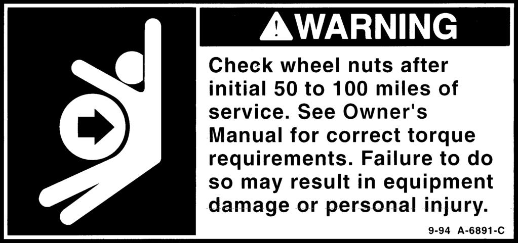
11 SAFETY Wheel Torques Proper torquing and retorquing the wheel nuts are critical to prevent the premature loss of wheel equipment Wheels must be checked and retorqued after 50 to 100 miles of use. This is important every time you change a wheel. Safety 2-8


12 INSPECTION PROCEDURE BEFORE TRIP WARNING Be careful when making inspections, hookups, and repairs to avoid personal injury. Make sure parking brakes are properly activated or that wheel chocks are in place to avoid sudden or unexpected movement of the trailer which could result in bodily injury. IMPORTANT It is the Operator s responsibility to conduct a safe and accurate pre-trip inspection o fthe vehicle including brake condition and proper adjustments and be satisfied that the vehicle is in safe operating condition. See 49 CFR Parts 383 and 396. Brake and Electrical Controls Check and clean all lights and reflectors. Proper operation of lights and brakes requires a firm seal between the air brake glad-hands, as well as a clean, secure contact of electrical connections. Inspect glad-hand for rubber washer damage and cracked housings. Check air hoses for cracking and check outside surfaces of electrical cables and connections for fraying. Check the operation of the brakes and slack adjusters as required. Drain the moisture from the air brake system each day by opening drain cocks on the air tanks. Fifth Wheel and King Pin Engagement After hook up, check for positive engagement of the lower fifth wheel and king pin. Apply trailer brakes and attempt to move the tractor forward to insure that the fifth wheel and king pin are positively locked. CAUTION PLASTIC KING PIN LINERS (LUBE PLATE) cannot be installed on Wilson Trailer Company king pin assemblies. A lube plate changes the king pin interface dimensions of the fifth wheel lock. This may result in coupling difficulties, premature lock wear, and a potential dropped trailer. Only trailers specifically designed for king pin plate liners may be so equipped. 3-1 Operation


13 INSPECTION PROCEDURE BEFORE TRIP Door Locks Check all clean-out door locks, access door locks, side door locks, and gate locks before each trip to insure that they are in proper working order. Any door or gate locks or keepers which show excessive wear should be replaced immediately. Care should be taken to keep area around the door frame clear of any debris or animal wastes. A build-up of refuse may result in more pressure being applied to the locks than they were designed to withstand. CAUTION Door and gate locks which show excessive wear should be replaced immediately. Tires Check tires frequently for cuts and abrasions. Check tire pressure daily and keep inflated as recommended by the tire manufacturer. Remove foreign objects that may be lodged in the tire threads or between dual tires. Wide Base Single Tires & 2 Offset Wheels Wilson Trailer recommends that customers using wide based super single tires and 2 offset wheels specify axles and hubs with the same size inner and outer bearings. When using wide based super single tires and 2 offset wheels our vendors require using axles and hubs with the same size inner and outer bearings due to the increased loading that occurs at the outer wheel bearings. Hendrickson will only allow straight spindle with the same inner/outer bearing on their axles/ suspensions (Intraax/AANT) when running wide base super single tires. Meritor or IMT axles with the 2 offset wide base super single wheels require you use the same size inner/outer bearings. The increased load from using wide based super single tires and 2 offset wheels on wheel ends with tapered bearings could result in bearing failure. Wilson Trailer will not provide warranty to customers using wide based super single tires and 2 offset wheels with tapered bearings. Operation 3-2

14 INSPECTION PROCEDURE BEFORE TRIP Hub Lubricants Check and maintain proper level of lubricant in hubs. Hubs using oil lubricant will have clear hub windows and the oil level will be clearly visible. Be sure the oil level is at the fill line noted on the hub window. Hubs equipped with semi-fluid grease will retain the grease between the bearings and no lubricant visual check is possible at the hub window. Gray hub windows are installed on hubs with semi-fluid grease to identify the lubricant and prevent concern over no visible lubricant. Outer bearings should be inspected every 100,000 miles following the procedures listed in the Hub and Bearings: Bearing Lubricant - Semi-Fluid Grease section of this manual. Additionally, hubs with semi-fluid grease should be periodically hand-checked for excessive heat or significant differences in temperature from one hub to another. To handcheck the hubs, immediately after driving at highway speeds for at least 50 miles touch each hub to test for heat buildup. Further inspection is needed if a hub is excessively hot or noticeably hotter than the other hubs on the trailer. (Rev. 8-03) NOTICE: Do not add oil to hubs equipped with semifluid grease. If mixing of lubricants occurs, remove the lubricant and re-install the proper lubricant as soon as possible. (Rev. 6-97) Hub Maintenance Unless otherwise specified on the trailer order, the dual wheel stud standout is 1-3/8 for both steel or aluminum wheels, as recommended by wheel manufacturers. When a broken stud is replaced, the stud on each side of it should be replaced. If more than two stud are broken, replace all studs. CAUTION If longer studs with a wheel stud standout of 1-5/8 have been specifically requested and installed, they must be used only with aluminum wheels. Use of steel wheels may result in improper seating of inner capnuts, causing equipment damage, personal injury or both! 3-3 Operation


15 INSPECTION PROCEDURE BEFORE TRIP Livestock Trailer Owner s Manual Wheels and Rims Check all wheel nuts for tightness after the first 50 to 100 miles of service and before each trip. Manufacturer s Recommendations To prevent Joint settings - eliminate any material soft enough to cold form out of the wheel-hub-drum stack. Expect up to 25% loss in clamp load when the trailer is put into service, customers need to re-torque wheel retaining nuts to recommended torques. No paint is allowed on mounting surfaces and stud threads. Check and maintain proper level of oil in wheels. Check all metal surfaces thoroughly while making tire inspections and during tire changes and look for: 1. Excessive rust or corrosion build up. 2. Cracks in metal. 3. Bent flanges or components. 4. Loose, missing, or damaged nuts or clamps. 5. Bent or stripped nuts. 6. Incorrectly matched rim parts. Replace damaged components, making sure that replacement parts are made with proper sized and type parts. NOTICE Excessively corroded or cracked rims are dangerous, particularly during removal. Deflate tires prior to removal of rims and wheels from the vehicle or personal injury could result. Operation 3-4


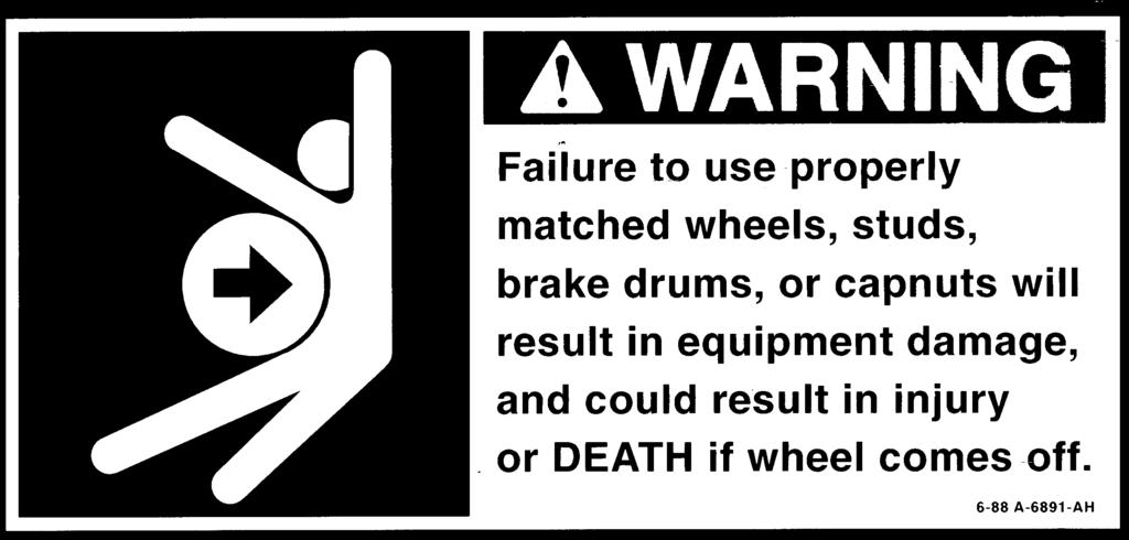
16 INSPECTION PROCEDURE BEFORE TRIP Disc Wheel Installation CAUTION Insufficient mounting torque can cause wheel shimmy, resulting in damage to parts and extreme tire wear. Excessive mounting torque can cause studs and capnuts to break and discs to crack in stud hole area. Check all parts for damage, including wheels and rims. Make sure that studs, nuts, and mounting faces of hub and wheels are free from grease. Replace any defective parts. Mount inner dual wheel over studs, being careful not to damage threads. Draw up nuts alternating in sequence shown. Do not tighten fully to permit uniform seating of nuts and insure the even face-to-face contact of wheels and hub. Tighten nuts fully, using same alternating sequence, to 450 to 500 ft. lb. torque. Mount outer wheel and repeat the entire procedure. In each case, be sure to tighten wheel nuts only to torque shown and maintain them at that level through periodic checks. Note: When inner cap nuts are retightened, be sure to loosen outer cap nuts several turns; then retighten them. CAUTION Be sure to use correct capnuts to match wheels. Grade 8 inner capnuts must be used with aluminum wheels. Wheel torque to be ft.lb. (Rev. 9-97) Wheel Nut Torques Torque for rim nuts or capnuts is expressed in foot pounds, and is the force of exerted in pounds multiplied by the lever arm or wrench length in feet. Example: 200 pounds x 2.2 ft. = 450 ft.lb. For Special disc wheel installations using single-flange nut attachment on dual wheels, see the manufacturer s recommended mounting procedures. 3-5 Operation


17 INSPECTION PROCEDURE BEFORE TRIP Mud Flaps Be sure mud flaps are securely in place. Gates Before traveling, be sure that: 1. All divide gates are secure in either an open or closed position. 2. Stationary deck model hand-operated front gate/ramp combination components are closed and secure. 3. All roll-up gates are closed and ropes are secured. Lift Deck SEE SUPPLEMENTAL LIFT DECK OPERATOR S MANUAL. Slider - Suspension If trailer is equipped with a sliding tandem, be sure all four (4) lock pins are locked in place and the manual stop bar at the rear of the slider is locked before moving the trailer. Operation 3-6


18 INSPECTION PROCEDURE BEFORE TRIP Air Ride - Suspension Before operating, the air ride must be set properly at the design height to get the correct load transfer to the suspension and the axle loads to balance. Check if the air bags are fully inflated and free of cuts and debris. The air controls need to work correctly and freely. These consist of the Full Suspension Dump and the Height Control Valve (HCV) attached to the rear suspension hanger. Spring - Suspension The spring suspension must be in good operating condition to transfer the loads equally to the axles. Check the springs for cracked or broken springs. Check for loose or missing bolts. Check to see if the equalizer is free to operate. Side Structure Check the trailer sides for inconspicuous damage to the top and bottom rails as well as the side structure. Any problems observed in the side structure should be corrected immediately to prevent the damage from extending further. Unrepaired damage could affect the safe load carrying capacity of the side structure. WARNING Use extreme caution when climbing the trailer side. Slippery surfaces or unpredictable animal behavior may result in personal injury. Punched side trailers are built with.080 aluminum side skin. Do not use the holes to hang heavy objects on the side. This could damage the side skin. Contact Wilson Trailer Company immediately for information on proper support of mounting brackets for such applications. 3-7 Operation

19 OPERATING INSTRUCTIONS Loading/Unloading To prevent unexpected trailer movement, exhaust the air from the suspension and set the parking brakes before adding or removing cargo. Summary of General Operational Guidelines 1. Do not back up a trailer with the trailer brakes engaged. 2. Do not park the trailer with the air suspension inflated. 3. Exhaust the air suspension before setting the parking brakes, unhooking from the tractor, or loading the trailer. (Rev. 6-97) Landing Leg Use on Livestock Trailers Landing gear legs are of two types: 1. Drop Leg style which uses a pin-in-hole support method. 2. Crank Down or Two Speed style which use a drive screw to raise and lower the trailer. The standard construction of both of these landing gear types do not allow fully loaded dropping or dolly down support of a fully loaded trailer and should not be used for fully loaded application except in emergencies and for short periods. Drop Leg Style Crank Down Style Wilson Trailer has an option for fully loaded trailers dolly down which has added structure and allows support of full livestock loads for extended periods of time. (Rev ) 3-9 Operation

 (Figure 1) In addition to the normal release of spring brake using air, a built-in manual release is provided (See Figure 2).")
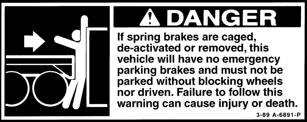
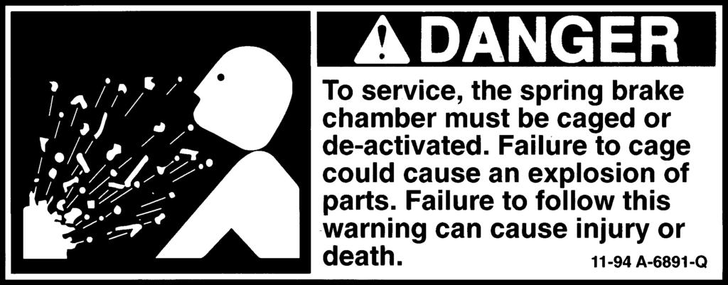
20 OPERATING INSTRUCTIONS Parking/Emergency Braking System This portion of the air brake system makes provision for parking a loaded vehicle on a grade and for emergency stopping in the event of a failure of air supply in the service brake system. Air pressure within the parking brake chamber is required to release the spring brake. An air reservoir is provided to store enough air to release the brakes at least once by means of the tractor parking brake control, if there is an air line failure. (See Figure 1.) (Figure 1) In addition to the normal release of spring brake using air, a built-in manual release is provided (See Figure 2). It allows easy release of the spring brake for relining the brakes or for moving the trailer in the absence of air pressure. (Figure 2) DANGER To service, the spring brake chamber must be cages or de-activated. Failure to cage could cause an explosion or parts. Failure to follow this warning can cause injury or death (Rev. 1-02) (A Q) DANGER If spring brakes are caged, de-activated, or removed, this vehicle will have no emergency parking brakes and must not be parked without blocking wheels nor driven. Failure to follow this warning can cause injury or death. (Rev. 1-02) (A P) Operation 3-8


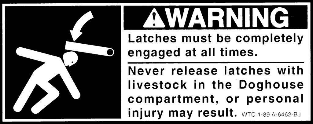
21 Front Counter-Balanced Gate and Ramp Livestock Trailer Owner s Manual OPERATING INSTRUCTIONS A counter-balanced front gate and ramp combination is provided on most stationary deck drop center trailers. It is used to accommodate loading and unloading the front lower compartment. Operating in unison, the ramp is lowered as the bottom of the upper gate is raised toward the roof of the trailer. CAUTION To be safe, always maintain a full arm's length distance from the upper gate while activating the gate and ramp combination. This is especially important when operating the gate while livestock are in the front compartment. (Animals may climb or jump onto the ramp while it is in a partially opened or closed position and force the gate upward.) Do not stand under the front counter-balanced gate and ramp when it is being operated. WARNING Always stand clear of the swinging arc of interior divide gates to prevent kicking animals from causing serious personal injury. Rear Compartment Dog House Dog houses are provided in many drop center trailers. When the trap door is in the vertical position, the latches must be completely engaged at all times. CAUTION Never release the trap door latches with livestock in the dog house compartment. To do so may result in serious personal injury. Operation 3-10
22 OPERATING INSTRUCTIONS Suspension - Sliding The "Slider" features manual locking of the suspension by insertion of four (4) lock pins, one at each corner of the lower unit. Repositioning Your Slider NOTICE Always reposition the slider with the trailer on a level surface. 1. Unlock handle and move manual stop bar to new location. Relock handle in place. 2. Draw out pull bar to release spring-activated lock pins. Lock pins are thus withdrawn and unit is free to be repositioned. 3. Set trailer brakes and slide trailer body forward with tractor to reduce weight on the tandem; slide trailer body backward to increase weight on the tandem. 4. After proper positioning is accomplished, lock manual stop bar at rear of slider Operation


 DO NOT continue to back trailer with the trailer brakes applied.")
23 OPERATING INSTRUCTIONS Suspension - Air Ride Special care must be used when backing, parking, and loading a trailer equipped with air ride suspensions. NOTICE TRAILING BEAM AIR SUSPENSION Continuing to back a trailer with the trailer brakes locked will cause the air suspension beams to rotate and raise the bed of the trailer. Excessive rotation of the air suspension beams may: (A) Pull apart the shock absorbers. (B) Damage the height control valve linkage. (C) Over extend and fail the air springs. Supporting the trailer on the landing gear with the beams rotated and the trailer brakes locked is dangerous! Tire rotation as the suspension beams return to their normal height will push the landing gear and may damage or fail the landing gear. To prevent the above problems: (A) DO NOT continue to back trailer with the trailer brakes applied. (B) After positioning the trailer, disengage the trailer brakes, allow the suspension to return to its normal position, and reapply the trailer brakes prior to supporting the trailer on the landing gear. PROPER POSITION IMPROPER POSITION Liftable Suspension Liftable suspensions are suspensions that may be raised to lift the tires off the ground, reducing tire wear when the full capacity of all the suspensions are not required. Liftable suspensions are raised and lowered by activating the switch in the control box, typically mounted near the center on the driver's side of the trailer. IMPORTANT Raising a liftable suspension with the trailer loaded may overload and damage the remaining suspension(s), wheel components, and trailer frame. Do not raise liftable suspensions on loaded trailers, even for low speed maneuvering. (Rev ) Operation 3-12


24 OPERATING INSTRUCTIONS Axle Auto Lower System aka ILAS Valve If your trailer has a lift axle, it may also have a Axle Auto Lower System installed. This system senses the application of cargo weight into the trailer and automatically lowers the lift axle or axles when a specific cargo weight is reached. This system is required in areas of Canada in order to get credit for the use of a lift axle. Also, in some cases this system may be installed by the factory to protect your trailer structure from cargo weight when the support of the lift axles is required. In those cases the lift axle will be automatically lowered to provide structural support to the trailer. Tapering or disabling the system may void your warranty. Mechanical repairs or adjustments must be done by a factory approved service shop. How It Works Suspension air bag pressure on a non-liftable axle is sensed by a special air valve, automatic lower valve, aka, ILAS valve. When cargo is loaded onto the trailer, the pressure in the suspension bags increases. When a predetermined air pressure value is reached, the lift axles will be lowered and their suspension bags will receive pressure to suport the trailer. Automatic ILAS Valve The system may be one of two types, Manual, or Automatic with manual overdrive. The Manual system will lower the axle by itself when cargo is applied but requires the operatro to raise the axle manually (after cargo has been removed) by operating a push knob on the ILAS valve. the Automatic with manual overdrive system will automatically lower and raise the axle according to cargo weight but allows the operator to force the lift axle down as desired and raise it again if there is little cargo weight. There may be trailer configurations where the Manual system is the only one offered. Manual ILAS Valve (Rev ) WARNING CRUSHING HAZARD Raising and lowering of life axles is controlled automatically and may activate at any time. Keep clear of suspensions and tires at all times. Lower axle manually before servicing Operation

25 OPERATING INSTRUCTIONS Liftable, Regulated Axle (Dial Down) For trailers equipped with a Liftable, Regulated alxe, the air controls are on the roadside of your trailer. This box contains a 160 psi regulator along with a locking detent lift control valve, and a manually adjustable regulator knob. The regulator is adjusted manually to control the pressure of the lift axle ride bags. Validate Your Load To control the load on your lift axle, with the trailer loaded, pull the regulator knob and turn to the desired pressure. This can be accomplished by placing the lift axle on a scale while the adjustment is taking place. Once the desired load is on the axle, push the knob to lock the adjustment in place. Operating Lift Axle To lift or lower the axle, rotate the locking detent lift control on the valve counterclockwise 1/4 turn to a horizontal position to lift and then back clockwise 1/4 turn to a vertical position to lower the axle. The lift axle needs to be lifted when the trailer is empty and lowered when the trailer is loaded. Lowering a preset axle when the trailer is empty will lift other axles off the ground. If the axle were to be connected to an electical power, the lift has a personal safety feature that will lift the axle when the power is disrupted. NOTE Loading the axle should never exceed the wheel, tire, or axle rating. This is listed on the Federal Registration Plate under the GAWR Rating. (Rev ) Operation 3-14
26 OPERATING INSTRUCTIONS Load vs Pressure Chart 25,000 Axle Load (lb) vs. Air Bag Pressure (psi) SAF CBX H Intraax (AAT, AANT, AAL, AANL) RideWell RSS-232/T (lift/steer) H Composilite ST lift 20,000 15,000 Axle Load (lb) 10,000 5, Air Bag Pressure (psi) Actual values can vary depending on various factors (ex. Ride height). Use this graph as a guide. Set values conservatively. Verify actual axle load on a scale. For singled out axles: Do not exceed 12,000 lb on any singled out (half a dual on each wheel end) axle. Verify individual axle load on a scale. Note: Some lift box configurations will only read pressure at the guage with a load on the trailer. If in doubt as to your suspension type set the dial down pressure at 30 psi and fine tune on a scale with a conservative load on the trailer. (Rev ) 3-15 Operation

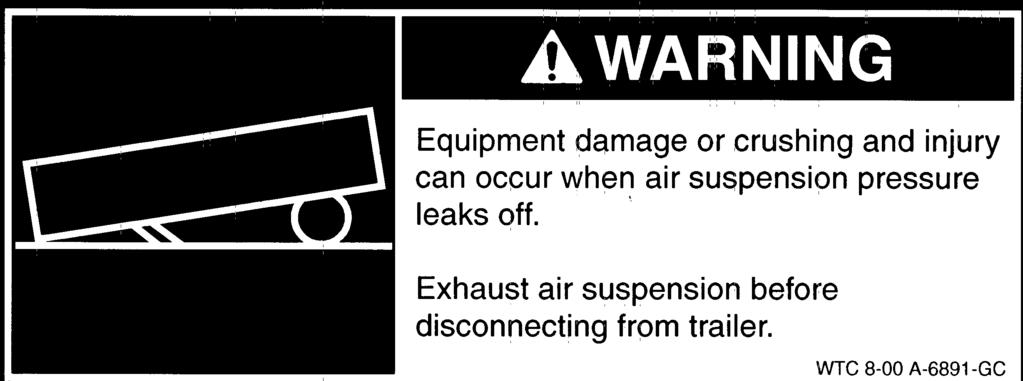
27 OPERATING INSTRUCTIONS Parking and Dock Walk CAUTION Personal injury or property damage could result from trailer movement due to failed landing gear resulting from dock walk. When parking a trailer, eliminate dock walk conditions by completely exhausting the air suspension to lower the trailer before engaging the parking brakes. NOTE When the trailer is equipped with manual or automatic dump valves, it is the responsibility of the operator to ensure that the air suspensions are exhausted when the trailer is parked for loading and unloading and unhooked from the trailer. Individual dump valves are not recommended on a Wilson Livestock trailer. Individual dump valves will void warranty. (Rev ) Trailers equipped with air ride suspensions are subject to dock walk, or forward creeping, when parked with the suspension inflated and the trailer brakes locked. This can be especially hazardous when the trailer is parked on the landing gear legs, as enough forward force can result with a loaded trailer to damage or buckle the landing gear legs and braces. To reduce the possiblity of dock walk, Wilson Trailers are equipped with a two-position manual valve for exhausting the air suspensions. Activate the suspension exhaust before engaging the trailer s parking brakes and unhooking from the trailer. The manual dump valve is typically located on the road side near the rear drop of the trailer. The OFF (fill) position is the normal operating position with the suspensions inflated. The ON (dumped) position exhausts the suspensions. An optional automatic suspension dump valve is available in place of the manual valve. The automatic valve is activated to exhaust the suspension whenever the emergency air line pressure is zero, such as when the parking brakes are engaged or the gladhand is disconnected from the front of the trailers. To position a trailer with automatic exhaust valves tightly against a loading dock in the lowered position, it may be necessary to set the brakes and fully exhaust the suspension, release the parking brakes and quickly move the trailer backward slightly then re-engage the brakes before the suspension has time to inflate. (Rev. 6-97) IMPORTANT The parking brakes may engage more quickly than the suspension will exhaust, resulting in dock walk conditions. Allow the trailer to walk forward as the suspension exhausts by releasing the tractor brakes. Do not unhook from the trailer before exhausting the suspensions and setting the trailer brakes. Operation 3-16
28 OPERATING INSTRUCTIONS Tire Changing Procedure Precautionary Notes: Keep unnecessary personnel away when raising and lowering trailer and changing tires. Do not climb under a raised trailer. Jack Points Do not leave a raised trailer unattended. Avoid raising a loaded trailer whenever possible. NOTE It is acceptable to position a single lifting device near the center of an axle on an unloaded trailer only. Do not attempt to raise a loaded trailer with a single lifting device located at the center of an axle. 1. Position trailer on a level, hard surface capable of supporting the total vehicle weight and lifting equipment. 2. Set brakes and block wheels at other locations to prevent movement. 3. Be sure air ride suspensions are inflated and an air source is available to maintain inflation. NOTE It is the responsibility of the individual raising the trailer to ensure that the placement of the lifting equipment is secure and on an adequate structure. 4. If a loaded trailer must be raised for changing tires, take appropriate precautions to reduce risk of tipping, load shifting, or structural damage, including: Lower landing gear to support and stabilize the front of the trailer. Use two lifting devices and raise both sides of the trailer evenly to prevent leaning and tipping. 5. Position the jacks or lifting devices under the axle, as close to the outer end as possible. Use care to avoid placement that will cause contact and damage to other components such as brake chambers, cam shafts, U-bolts, and slack adjusters. 6. Raise the trailer at a slow, steady rate until the tires to be removed are off the ground. If using two lifting devices, raise both sides of the trailer evenly to avoid leaning and tipping. 7. Position trailer supports under trailer frame or axle to prevent unexpected lowering of the trailer. 8. Remove the nuts securing the tires and remove the tire(s) using a tire fork or a similar device to lift the tire(s) Operation
29 OPERATING INSTRUCTIONS Tire Changing Procedure NOTICE Wheel nut torque must be checked within the first miles of operation following installation. Failure to do so may lead to loose wheels and result in lost wheels and personal injury. 9. Install the replacement tire(s). Refer to the appropriate section of the Owner s Manual for specific instructions for hub piloted, stud piloted, or spoke wheel installation. 10. Torque the securing nuts to the values specified in the appropriate wheel installation section. Torque Values: Hub Piloted Stud Piloted Spoke ft.lb ft.lb ft.lb. 11. Remove trailer supports. 12. Lower the trailer to the ground at a slow, steady rate. If two lifting devices are used, lower both sides evenly to avoid leaning and tipping. Watch for pinch points to ensure no electrical or pneumatic lines will be damaged. 13. Remove lifting devices and check wheel nuts to ensure they are torqued to the specified values. 14. Inspect suspension components for damage or improper adjustment resulting from raising and lowering the trailer. Repair any damaged components as necessary. 15. Remove blocks from wheels. (Rev ) Backing Backing a trailer equipped with air suspension with the trailer brakes locked will cause the suspension beams to rotate, raising the trailer bed and possibly damaging components. Trailer brakes must be released before backing. Operation 3-18

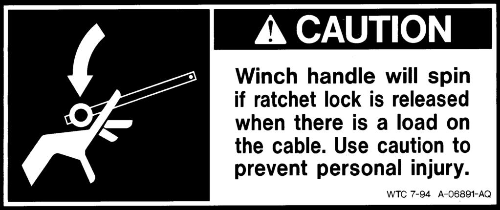
30 OPERATING INSTRUCTIONS Operation of the Nose Carrier If your Wilson trailer is equipped with a nose tire carrier, a cable winch is provided for lifting the spare tire up to rest on the tire carrier brackets. These components are located on the front of the trailer. Storing the Tire To lift the spare tire on to the carrier brackets, insert the cable through the tire and attach securely. Move the winch safety latch into the SAFETY position and proceed to turn the crank in a clockwise direction. After the spare tire is resting on the brackets, secure it to the trailer by attaching the clamping channel with the T-bar, both of which are provided with your new Wilson Trailer nose spare tire carrier option. When the tire is secured in place, release the tension on the lifting cable, and place the latch on the winch in the SAFETY position. Check the cables for fraying. If any deterioration is observed, replace the 1/4 galvanized aircraft cable immediately. Removing the Spare Tire Reverse the safety latch from the RAISE position to the LOWER position. Lift the tire off the tire carrier brackets and slowly turn the crank in a counter-clockwise direction. Keep a tight grip on the handle and be careful not to let the tire descend too quickly. And always stand a safe distance from the tire to avoid bodily injury Operation
31 King Pin and Fifth Wheel Lube Plates Livestock Trailer Owner s Manual OPERATING INSTRUCTIONS Trailer king pins are built to tight tolerances to ensure positive and secure engagement with tractor fifth wheel coupler. Worn, damaged, or modified king pins can prevent proper coupling and may cause the trailer to unhook unexpectedly. To ensure proper connection between the tractor and trailer: Do not use trailer king pins or tractor fifth wheels that are damaged, worn, or modified, or that are improperly equipped with lube plates (see below). Back the tractor firmly into the trailer until the king pin engages the fifth wheel coupler and locks. With the trailer brakes locked and before raising the trailer landing gear, pull the tractor forward to be sure the coupler is securely locked. IMPORTANT Avoid coupling problems: Do Not install a lube plate on a trailer that is not specifically built for lube plates. Do Not operate a trailer built for a lube plate without a lube plate installed. Lube Plates When properly installed and used, lube plates can increase equipment life and reduce regular maintenance by providing permanent lubrication between the tractor fifth wheel and trailer pickup plate. However, improper installation or misuse of lube plates can prevent proper coupling of tractors and trailers and may cause damage or rapid wear of king pin and fifth wheel parts. The thickness of a lube plate, either installed on a trailer not designed for it or removed from a trailer built for one, can prevent proper coupling of the trailer king pin with the tractor fifth wheel, possibly causing the trailer to unexpectedly disconnect from the tractor. Lube plates should only be used on trailers specifically designed and built with longer king pins and should not be removed from trailers designed to have them installed. IMPORTANT To avoid excessive wear on trailers equipped with an aluminum pickup plate: Always attach the lube plate securely to the aluminum pickup plate. Do Not use quick-attach lube plates such as those that attach only to the king pin shaft with a retaining ring. Do Not use lube plates attached to the tractor fifth wheel. Lube Plates and Aluminum Pickup Plates When lube plates are installed on trailers with aluminum pickup plates, the lube plate must be securely attached to the aluminum pickup plate. Grit or debris trapped between a lube plate and an aluminum pickup plate will rapidly wear the aluminum plate if the lube plate is allowed to move against the aluminum pickup plate. Operation 3-20

32 HUB AND BEARINGS Axilok Nut Removal & Installation Procedures WARNING Do not use chisel, hammer, or any power tool to remove the Axilok product. Equipment Required: 6-Point socket, sized according to the markings on the face of the Axilok. AX /4 AX /8 Torque Wrench Dial Indicator Axilok Component View FIGURE 1 1. Install correct size 6-point socket completely over the hex of the Axilok. Be sure that both the locking clips are completely disengaged from the retainer cage, permitting free rotation. Refer to Figure Turn counterclockwise to remove Axilok. If Axilok does not move freely, stop removal. Check that the socket is completely and fully engaged on the Axilok and that the locking clips are fully retracted from the retainer cage slots. If Axilok still will not turn freely, rotate slightly clockwise, to tighten, and then loosen again. The nut should rotate counterclockwise freely. 3. Continue counterclockwise rotation until Axilok threads disenage from the spindle threads. Checking Position of Locking Clip Tabs FIGURE 2 NOTE Light burnishing of the retainer cage bearing surface after use is normal. AXILOK Socket Size Initial Initial Final Final 6-Point Torque (in Backoff Torque (in Backoff foot-pounds) foot-pounds) AX / /2 turn 75 1/8 turn AX / /2 turn 75 1/8 turn TABLE General Maintenance
33 HUB AND BEARINGS Axilok Nut Pre-Installation Procedures WARNING Axilok may not be compatible with all axles currently in use. Do not use Axilok on an incompatible axle. Review appropriate manufacturer s bulletins for axles not compatible with Axilok. Inappropriate use could produce a wheel off condition, which may result in serious bodily injury and/or equipment failure. If Axilok has not been selected as standard equipment by the Original Equipment Manufacturer (OEM), do the following: Review axle manufacturer s bulletins to be sure axle is compatible with Axilok. OR, Remove hub to fully expose spindles and its slot or D flat. Carefully measure the width and depth of the spindle slot or D flat at the outboard end of the spindle and at the last full thread of the slot or D flat. If the measurements are identical, Axilok may be used. If not, DO NOT use Axilok on this spindle. Use a conventional wheel nut retaining system. Refer to Figure 3. Before installing Axilok, check the following: 1. Inspect Axilok for two locking clips. Refer to Figure 1. Each locking clip should be securely fastened to the nut body and have a rivet that passes through the top of the locking clip body. Each locking clip should have a locking clip tab protruding completely through the retainer cage adjustment slot (when properly aligned and not compressed by a socket). Refer to Figures 2, 4, and 5. Locking clips should not be bent, cracked, or broken. 2. Inspect Axilok retainer cage condition. Measuring Spindle Slot or D Flat FIGURE 3 There should be no cracks or other damage to the retainer cage. Retainer cage should be secure to the nut body and not fall off when the locking clips are compressed by the socket. The retainer cage tab or D flat should be free of damage, such as cracks, scarring, gouges, or distoration. Refer to Figure Inspect Axilok threads. The threads should show no signs of wear or damage. Wipe the threads to remove excess oil or debris. General Maintenance 4-2


34 HUB AND BEARINGS Axilok Nut Pre-Installation Procedures CAUTION Do not use Axilok assembly with hubs that have internal bearing spacer systems except as directed by the vehicle manufacturer. 4. If Axilok fails any of the checks above, the Axilok is unfit for use. DO NOT USE. Replace the unfit Axilok with a new Axilok, and repeat all checks. 5. Free Rotation Inspection. This test will check for nut and socket compatibility. With correct size 6-point socket turned upside down, insert Axilok completely into the socket, compressing locking clips. Retainer cage should spin freely with no interference between locking clip tabs and retainer cage. If locking clip tabs interfere with rotation of the retainer cage, the socket is not fully compressing the locking clips. This indicates that the socket is the incorrect size, worn, or out of specifications and must be replaced. Refer to Figure 2. Axilok Nut Installation Procedures NOTE If installing Axilok on vehicles purchased from an OEM, with Axilok as original equipment, follow the OEM s specific installation instructions. Locking Clip Tabs Broken FIGURE 4 Locking Clip Tabs Improperly Positioned FIGURE 5 1. Before installation, perform pre-installation checks: Be sure the spindle slot is clean and free of burrs and foreign material before installing Axilok. Be sure the thread size is the same on both components. Put a few drops of oil through one of the retainer cage holes. This will ensure friction-free movement. 2. Put Axilok in the correct 6-point socket (refer to Equipment Required) and verify that the locking clips are compressed. Refer to Figure 2. Retainer cage should spin freely. 4-3 General Maintenance

35 HUB AND BEARINGS Axilok Nut Installation Procedures 3. Align Axilok retainer cage tab D flat with spindle slot or D flat. Be sure to start and run down the Axilok by hand. Do not use power tools. Rotate the socket clockwise until contacting bearing. Do not overtorque. Refer to Table 1 for specific torque values. Rotate the socket clockwise until contacting bearing. 4. Using a properly calibrated torque wrench, torque Axilok to the initial torque of 200 ft.lbs. while rotating hub. Back off 1/2 turn. Tighten to final torque while rotating hub. Refer to Table 1. Back off 1/8 turn. This will provide end play. Refer to Figure 6. WARNING If locking clip tabs do not protrude through the adjustment slots, rotate Axilok slightly clockwise. Refer to Figures 2, 4, and 5. If locking clip(s) are broken replace Axilok and repeat installation procedures. 5. Remove socket and verify locking clip tabs have engaged the adjustment slots in the retainer cage. Refer to Figures 2, 4, and Measure end play using a dial indicator. If correct end play is not achieved, adjust according to Adjustment Increments shown in Table 1. Rotate Axilok clockwise to reduce end play. (Example: from.004 to.002 end play.) Rotate Axilok counterclockwise to increase end play. (Example: from.001 to.003 end play.) This same procedure can be used to achieve a controlled pre-load condition. (Example: from.001 end play to.001 pre-load.) 7. After end play adjustment, make sure that both locking clip tabs are protruding through the slots in the retainer cage. Refer to Figures 2, 4, and 5. General Maintenance 4-4

 A: Tighten the nut to 200 ft-lbs.")
 A: 1. Tighten the nut to 100 ft-lbs.")
 A: Tighten the nut to 100 ft-lbs.")
36 HUB AND BEARINGS Spindle Nut & Wheel Bearing Adjustment Procedures PRO-TORQ Installation Procedure & Wheel Bearing Adjustment STEP 1 Remove the keeper from the nut Use a screwdriver to carefully pry the keeper arm from the undercut groove on each side until the keeper is released. STEP 2 Seat the bearing (With hub or hub/drum only) A: 1. Tighten the nut to 200 ft-lbs. Spin the wheel at least one full rotation. 2. Tighten the nut to 200 ft-lbs. Spin the wheel at least one full rotation. 3. Tighten the nut to 200 ft-lbs. B: Back the nut off until it is loose. STEP 1 (With hub/drum/wheels) A: Tighten the nut to 200 ft-lbs. while the wheel is rotating. B: Back the nut off until it is loose. STEP 3 Adjust the bearing Using a torque wrench STEP 2 (With hub or hub/drum only) A: 1. Tighten the nut to 100 ft-lbs. Spin the wheel at least one full rotation. 2. Tighten the nut to 100 ft-lbs. Spin the wheel at least one full rotation. 3. Tighten the nut to 100 ft-lbs. B: Back the nut off one raised face mark. STEP 3 (With hub/drum/wheels) A: Tighten the nut to 100 ft-lbs. while the wheel is rotating. B: Back the nut off one raised face mark. 4-5 General Maintenance
37 HUB AND BEARINGS Spindle Nut & Wheel Bearing Adjustment Procedures STEP 4 Install the keeper (Orange side facing out) A: Insert the keeper tab into the undercut groove of the nut and engage the keyway tang in the axle keyway. Insert keeper tab with bent legs facing out. STEP 4 B: Engage the mating teeth. C: Compress and insert the keeper arms, one at a time, into the undercut groove with a screwdriver. (For Steering Spindle Nut , , , and ) A: Align the flat of the keeper with the milled flat on the spindle and insert the single keeper tab into the undercut groove of the nut. Insert keeper tab with bent legs facing out. B: Engage the mating teeth. C: Compress and insert the keeper arms, one at a time, into the undercut groove with a screwdriver. STEP 5 STEP 5 Inspect the installation A: Make sure that the keeper tab and keeper arms are fully seated into the undercut groove. Inspect keyway tang to insure it does not contact the bottom of the keyway. If contact exists, immediately notify your PRO-TORQ representative. WARNING PRO-TORQ ADVANCED AXLE SPINDLE NUTS PRO-TORQ is a registered trademark of STEMCO Inc. Failure to follow this instruction could cause the wheel to come off and cause bodily injury. The PRO-TORQ Spindle Nut is sold as an assembly with the keeper in place. DO NOT attempt to place the nut on the spindle or tighten or loosen the nut on the spindle while the keeper is locked inside the nut. Doing so may deform the keeper and allow the nut to unthread during operation. DO NOT bend or manipulate keyway tang in any way. Doing so may cause the tang to break off in service. Failure to back off the nut will cause the bearings to run hot and be damaged. General Maintenance 4-6
38 HUB AND BEARINGS Wheel Bearing Inspection Periodic inspection of wheel bearings and lubricants as well as regular lubricant changes is necessary for good maintenance and maximum wheel bearing life. The hub and/or wheel assembly must be properly cleaned to obtain optimum bearing life. This also applies to field service. When adding or checking oil level, make certain cap and plug are cleaned. This will minimize the possibility of dirt and road grime entering the system. Do not allow parts that have been cleaned and dried to remain dry for long periods of time. If bearings are not to be used immediately, they should be packed and coated with wheel bearing lubricant and wrapped in clean waxed paper. This will prevent corrosion of bearing surfaces. Bearing Lubricant NOTE The Integrated Sentinel Hub Cap includes a filtering system in the colored cap in the window. This colored cap in the center of the new hub cap is NOT to be removed. The lubricant is to be added through the pipe plug on the side of the hub cap. (Rev. 6-04) The lubricant change interval depends on the type of lubricant used, oil or semi-fluide grease. Oil levels should be checked at least every 1,000 miles (1,600 km), but can easily be checked in daily inspections. Oil should be changed whenever seals are replaced, brakes are relined, or at least once each year. Fill hubs with new oil to the level indicated on the hub window using HD80-90 heavy duty oil. Semifluid grease (gray hub windows) does not require regular changing, and need not be changed unless the lubricant becomes contaminated, leaks out, or is removed to replace seals or bearings. To install semi-fluid grease: 1. Install the inner bearing, inner seal, and hub. 2. Fill the cavitiy between the bearing races with approximately 50% of the cavity with semi-fluid grease. (Rev ) 3. Install the outer bearing and adjust end play as noted in the "Wheel Bearing Adjustment Procedure" section. 4. Install the hub cap and seal. Do not put grease in the hub cap. NOTE Do not mix oil and semi-fluid grease lubricants or add oil to hubs equipped with semi-fluid grease. Although mixing oil and semi-fluid grease lubricants are unlikely to cause component damage, it is recommended that mixed lubricants be removed and replaced with the proper lubricant as soon as possible. (Rev. 7-97) 4-7 General Maintenance

39 BRAKES Brakes Effective March 1, 1998, all trailers with air braking systems are required to have ABS (Anti-Lock Braking System). See your supplemental troubleshooting guide for specific details concerning operation and repair. If you have any questions or concerns contact your Wilson Trailer Company Sales Representative. (Rev. 1-98) Proper maintenace of brakes is most vital. This includes lining inspection, and brake adjustment. A schedule for the periodic adjustment, cleaning, inspection, and lubrication of the brake equipment must be made according to experience and the type of operation. NOTICE Wheel bearings must be correctly adjusted before brake adjustments are made. Brakes must be adjusted as frequently as required for correct operation and safety. The adjustments must give correct clearance between the lining and drum, correct push rod travel, and correct balance between the brakes. Brakes must be cleaned, inspected, lubricated, and adjusted every time the wheel hubs are removed. During a major overhaul, the following parts must be carefully checked and replaced with genuine replacement parts if required: 1. Backing plates or spiders for distortion and loose bolts. NOTICE Brake lining must not be permitted to wear to the point that the rivets or bolts touch the drum. 2. Anchor pins for wear and correct alignment. 3. Brake shoes for wear at anchor pin holes or roller slots. 4. Camshaft and camshaft bushings for wear. 5. Shoe return springs must be replaced. 6. Brake linings for grease on the lining, wear, and loose rivets or bolts. 7. Drums for cracks, deep scratches, or other damage. General Maintenance 4-8
40 BRAKES Spring Brake In-Service Checking Procedures Haldex Spring Brakes should be inspected for proper operation on a routine basis. Inspection is recommended every 3 months or 25,000 miles. IMPORTANT Always Block Wheels to Prevent Vehicle from Rolling Before Performing any Brake Maintenance 1) Check overall condition of Foundation Brake Assembly including drums, shoes, lining, retainer/return springs, bushings and rollers. 2) Check for obvious Structural Damage to spring brakes, brake adjusters or cam shafts and replace per OEM specifications. 3) Hook up tractor or apply shop air and release parking brakes. Apply and fully release Parking Brakes several times while watching for brake adjuster movement. Adjusters should apply and retract at relatively the same distance for all wheel positions. 4) To verify equal push rod movement, measure each push rod from the Face of the Air Chamber to the Center of the Clevis Pin with brakes Fully Set or Parked. Apply air to chambers to release parking brakes and re-measure all wheel positions. All strokes should be within 1/8 of each other. 5) Applied Stroke at p.s.i. can also be used to measure in a similar way as step #4. Apply Service Brakes instead of setting Spring (Emergency) Brakes and record before and after push rod measurements. Measured push rod stroke should NOT exceed the CVSA recommended maximum readjustment limit of 2 for Standard 30/30 chambers and 2-1/2 for Long Stroke 30/30 s. 4-9 General Maintenance
41 BRAKES Spring Brake In-Service Checking Procedures NOTE Two styles of release tools are available, removable and permanently mounted depending on chamber model and manufacture. 6) To further verify proper spring brake operation, remove Dust Plug located in the parking spring end of chamber. Remove Caging Bolt (Release Tool) mounted in chamber side pocket. Insert by hand the T-End of release tool into the tool or inspection hole. Twist tool ¼ turn clockwise and positively engage and lock T-End into chamber slot. 7) If release tool cannot be engaged in chamber slot, closely examine the inspection hole with a flashlight and look for the Tool Slot being Offset to the Inspection Hole; thus preventing positive tool engagement. If slot is off center to inspection hole, replace the complete spring brake. DO NOT continue to operate if this procedure cannot be accomplished. IMPORTANT NEVER use Impact type tools on any spring brakes or permanent damage may result. IMPORTANT NEVER use Impact type tools on any spring brakes or permanent damage may result. 8) After release tool is installed and locked, install washer and jam nut. Run nut down to chamber base and tighten to 55 ft. lbs. with a hand wrench. Measure the dimension from the face of the brake chamber to the tip end of the release tool. Perform same procedure for all Spring Brake positions. Measurements should be relatively the same for all brakes if parking sections are functioning properly. 9) Haldex Life Seal style chambers have the release tool permanently mounted in rear chamber housing. To check Life Seal parking sections, back off release tool nut Counter Clockwise until tool comes to a definite internal stop applying approximately 55 ft. lbs. IMPORTANT DO NOT operate if proper release tool dimension cannot be achieved. Replace the complete spring brake as soon as possible. Measure dimension from face of brake chamber to the inside of the tool nut. Correct dimensions should be: 2.4 to 2.56 for Regular Stroke 30/30 chambers 2.9 to 3.06 for Long Stroke 30/30 chambers General Maintenance 4-10
42 BRAKES Automatic Slack Adjusters NOTICE The brake adjustment must be checked with psi air pressure in the brake chambers when the brakes are fully applied. 100 psi in the air tanks with the ENGINE OFF will supply psi in the chambers when the brakes are fully applied. If necessary, run the engine to increase the pressure to 100 psi. If necessary, turn the engine off and apply and release the brakes to decrease the pressure to 100 psi. -Spring Brakes Released -Service Brakes Not Applied -Spring Brakes Released -Service Brakes Applied Chamber Type (Size) Measure Measure (100 PSI in air tank -- Engine Off) MAXIMUM STROKE AT WHICH BRAKES MUST BE ADJUSTED PSI AIR PRESSURE IN THE AIR CHAMBER. CLAMP TYPE AIR CHAMBERS. CAM BRAKES. Stroke length not to exceed: 9 1-3/8 inches /8 inches /4 inches /4 inches /4 inches 24 long stroke 2 inches 30 2 inches /4 inches The following procedures are used to check the inservice adjustment (adjusted chamber stroke) of air brakes with slack adjusters. The procedures are divided into two groups: 1. Truck, tractor only, or tractor and trailer combination. 2. Trailer only. TRUCK, TRACTOR ONLY, OR TRACTOR AND TRAILER COMBINATION 1. Check the gauges in the cab to make sure that the air pressure in the tanks is 100 psi with the engine off and the auxiliary spring chambers released. 2. With the brakes NOT APPLIED, measure the distance from the bottom of the air chamber to the center of the large clevis pin on all the brakes. Record each dimension. 3. Have another person apply and hold one full brake application. 4. Repeat Step 2 and measure WITH THE BRAKES APPLIED. Record each dimension. 5. Release the brakes. 6. Calculate the adjusted chamber stroke of each brake. a. Subtract the dimension that was measured in Step 2 from the dimension measured in Step 4. b. The difference between the two dimensions is the adjusted chamber stroke. The adjusted chamber stroke MUST NOT BE GREATER THAN THE STROKE LENGTH SHOWN TO THE LEFT for that size of air chamber. c. If the adjusted chamber stroke you measured is greater than the maximum stroke shown, inspect the slack adjuster General Maintenance
43 BRAKES Automatic Slack Adjusters TRAILER ONLY 1. Connect the auxiliary air system to the SUPPLY or EMERGENCY port of the trailers air system. 2. Increase the air pressure to 100 psi MINIMUM to release the auxiliary spring chambers. 3. With the brakes NOT APPLIED measure the distance from the bottom of the air chamber to the center of the large clevis pin on all the brakes. Record each dimension. 4. Connect a second auxiliary air system to the SERVICE port of the trailer air system. 5. Increase the air pressure of the second air system to 85 psi to apply the service brakes. 6. Repeat Step 3 and measure WITH THE SERVICE BRAKES APPLIED. Record each dimension. 7. Calculate the adjusted chamber stroke of each brake. a. Subtract the dimension that was measured in Step 3 from the dimension measured in Step 6. b. The difference between the two dimensions is the adjusted chamber stroke. The adjusted chamber stroke MUST NOT BE GREATER THAN THE STROKE LENGTH SHOWN IN THE CHART for the size of air chamber. c. If the adjusted chamber stroke you measured is greater than the maximum stroke shown in the chart, inspect the slack adjuster. See manufacturer's instructions. (Rev. 2-93) General Maintenance 4-12
44 DISC WHEEL and TIRE ASSEMBLY Mounting Instructions Stud Pilot mount wheels have stud holes that are reamed straight through the wheel. Pilot bosses machined on the hub fit tightly to the center of the disc wheel. Pilot mount wheels may be steel or aluminum. Pilot mount wheels are secured with flange nuts. Use only the correct, matched parts when assembling disc wheels. Incorrect components can result in separation of the rim components which can result in a crash. Flange Outer Cap Inner Cap Flange Nut Disc Wheels Reamed Holes Brake Stud Hub HUB PILOTED Disc Wheels Spherical Chamfer Brake Stud Hub BALL SEAT Do not mix pilot mount disc wheels with ball seated disc wheels. This may result in broken wheels or loss of a wheel, resulting in a crash. Do not use heat to remove the flange nuts. If heat is used to remove a nut, the stud, nut and outer wheel must be replaced. It is imperative for the safety and life of your vehicle that rim/disc wheels and tire assemblies be correctly installed and fasteners properly torqued. To assure proper installation, perform the following operations: a. Use the correct flange nuts to match your wheels. Failure to do so may lead to loose wheels or significantly reduce product life, and may result in a crash. Before proceeding with the installation of the disc wheel make certain you are using the proper flange nuts. The pilot mounting uses M22 x 1.5 metric threads. The stud standout is at least 2.16". All studs are right-hand threads. b. Before proceeding, make certain that all tires are matched to within 3/4" of the same rolling circumference per the tire manufacturer's instructions. Do not use tires that do not meet this criterion. Doing so may result in unstable operation and significantly reduce service life. c. Always correctly match disc wheel parts. Failure to use properly matched parts could result in serious injury. Consult the disc wheel manufacturer's literature for the correct parts of your tire and disc wheel General Maintenance
45 DISC WHEEL and TIRE ASSEMBLY Mounting Instructions 5 7 HUB PILOTED TIGHTENING SEQUENCE RECHECK TORQUE AFTER FIRST 50 TO 100 MILES OF SERVICE All threads are right hand metric. Tighten flange nuts to 50 ft.lbs. following sequence shown. Check disc wheels for proper positioning on pilots and proper sealing against drum back. Tighten flange nuts to ft.lbs. torque following sequence shown d. The disc wheel must be correctly installed and nuts tightened to recommended torque to assure maximum service life and maximize safety. Assemble the disc wheel and tire in accordance with the disc wheel manufacturer's instructions. Failure to do so may result in serious injury or death. e. Make sure that all mounting surfaces are clean and free of rust, dirt, or excessive paint. A wire brush may be used to clean these surfaces. Freshly painted wheels must have ample time to dry. Wet paint will be compressed under the wheel nut clamping force and result in loose wheels. Assembling painted, dirty or rusty components can prevent the wheel from seating properly which can result in unstable operation and cause an accident. f. Remove and discard the two shipping nuts (if used) prior to installing the disc wheel. Rotate the hub so that one pilot pad is at top center or at 12:00 position. g. Position the inner disc wheel over the studs and wheel pads, being careful not to damage the stud threads. Make sure the disc wheel is flat against the mounting surface and there is clearance between the disc wheel taper and the brake drum. h. Position the outer disc wheel over the studs and wheel pilot pads being careful not to damage the threads. Be sure the valve stems for both the inner and outer tires are accessible. i. On two piece flange nuts, apply a drop of oil between the nut and the washer and on the threads of the nut. Make sure that the flange washer is not seized to the nut. Do not lubricate on the mounting surface of the drum or wheel. (Rev ) j. Install the two piece flange nuts and tighten to fifty (50) foot-pounds in the sequence shown. Starting at the top will help insure that the drum and wheels seat properly on their pilots. k. Check both disc wheels to be sure that they are properly seated on the hub assembly. If they are not, loosen the flange nuts and return to Step i. above. General Maintenance 4-14
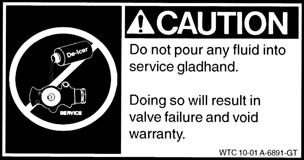
46 AIR SYSTEM COLD WEATHER OPERATION Thawing Frozen Air Lines "Prevention is the best medicine" DO'S 1. Do maintain freeze prevention devices to prevent road calls. Check (daily) evaporators or injectors so as not to run out of methanol alcohol. Check the air dryer for proper operation and change the desiccant when needed. 2. Do thaw out frozen air lines and valves by placing vehicle in a warmed building. This is the only method for thawing that will not cause damage to the air system or its components. DON'TS 1. Do not apply an open flame to air lines and valves. Beyond causing damage to the internal non-metallic parts of valves and melting or burning non-metallic air lines, THIS PRACTICE IS UNSAFE AND CAN RESULT IN VEHICLE FIRE! CAUTION Do Not pour any alcohol into service (blue) gladhand. Doing this will result in valve failure and void the warranty. 2. Air System Additives/Recommendations: The use of additives to thaw frozen air systems is sometimes required to get a trailer moving. While valve manufacturer s today use state of the art materials to provide the longest possible service life, the use of unapproved additives can affect valve service life. If a de-icer agent must be added, it is ONLY acceptable in the Red or Emergency Side of the air system, never in the Blue Control Side! Adding free liquid to the Blue control/application line can end up accumlating on top of the valve piston and can, depending on substance composition and volume, stop the function of the valve. Use only Methyl Alcohol as a de-icer. DO NOT USE Isopropyl Alcohol or Ethylene Glycol type Antifreeze. These substances will attack the Nitrile O-Rings in the valve, swell the O-Rings and remove the needed piston lubrication. If the wrong type of additive is added, valve function could cease and warranty will be declined. Additives should be introduced through an alcohol injector or similar type mechanism if equipped. If not, a small amount of Methyl Alcohol is acceptable - only in the Red/ Emergency side. Never pour more than 1/8 of an ounce into the Red gladhand, as a mist is all that is normally required and acceptable. (Rev ) 4-15 General Maintenance
47 AIR SYSTEM COLD WEATHER OPERATION Reservoir Draining Routine reservoir draining is the most basic step in reducing the possibility of freeze-up. While automatic drain valves relieve the operator of draining reservoirs on a daily basis, these valves MUST be routinely checked for proper operation. Air Travel Through Brake Valves Service Brakes: As driver presses the brake pedal, a pulse of air is put into the service line (blue). This air travels to the service relay valve. It enters the TOP of the valve and pushes a diaphragm down. The diaphragm pushes on a spring loaded cylinder which opens up and lets TANK AIR pass to the brake chambers and applies force to activate the brakes. Upon release of foot, air in brake chambers exhausts out the bottom of service valve. NOTE: The pulse air on top of the diaphragm dead ends there (so does any additive). Emergency Relay Valve: Supply air (red) passes (>70 psi) through valve and into air tank and builds up pressure ( psi). If the parking brake valve or emergency brake cab valve is activated, the air supply is dumped (stopped) and an internal spring applies the force to activate the brakes and air is exhausted out the bottom of the emergency relay valve. NOTE: Any additive introduced into emergency (red) side of air system will be exhausted. The only additive approved is methyl-alcohol. (Rev ) General Maintenance 4-16

 Your trailer s alignment should be checked on a regular schedule and the axles re-aligned when required to prevent unnecessary wear.")
48 PROPER AXLE ALIGNMENT Full Air Ride Suspension Complete details for inspection and maintenance can be found in the air ride suspension manufacturer's supplement provided with this manual. See warning emblems on trailer pertaining to air ride suspension. Spring Suspension IMPORTANT Your new WILSON trailer has been aligned at the factory with laser equipment. Re-aligning the axles will be the Owner s responsibility. (Rev ) Your trailer s alignment should be checked on a regular schedule and the axles re-aligned when required to prevent unnecessary wear. Check axle alignment with your trailer on a level surface with properly inflated tires, and with no load on the trailer. The king pin has a dead-center mark on the bottom side. To assure proper alignment, a steel tape measure should be run from the center point of the king pin to an identical spot or location on either side of the front axle. Your Wilson Trailer is equipped with screw-adjusted torque arms which are located on the driver's side of the trailer. Correction of mis-alignment is accomplished by adjusting the torque arms in and out, depending on which is required. The axles should be aligned to within 1/16" tolerance of the same location on either end of the axle. After aligning the front axle with the trailer king pin, then align the rear axle with the front axle. The front and rear axles should be parallel to each other, and both should be aligned within tolerance of the king pin. Make sure the torque arm clamp bolts are tightened back to ft.lb. when alignment is finished. Failure to keep the suspension properly aligned may cause tire scrub and suspension component strain General Maintenance
49 PROPER AXLE ALIGNMENT Spring Suspension After 500 miles or not later than 30 days after purchase, check carefully all the maintenance points listed below and make any necessary adjustments. Torque recommendations are listed in ft.lb. New-Oiled Clean-Dry 1. 3/4-16 U-Bolts 310 ft.lb. 420 ft.lb Torque Arm Bolts 590 ft.lb. 790 ft.lb. 3. 5/8-18 Step Equalizer Bolts 130 ft.lb. 170 ft.lb. 4. 5/8-18 Spring Retainer Bolts 35 ft.lb. 50 ft.lb. 5. 1/2-20 Torque Arm Clamp 65 ft.lb. 85 ft.lb. Bolts (Rev ) Tandem alignment should be checked and corrected if necessary after this initial break in period. Check all suspension bolts no less than every 6 months. They should be tightened to the above torque specifications. (Remember lubricants or sealants on the threads reduce torque readings drastically, and paint, corrosion, or road debris on the threads increase readings.) Check for and replace worn bushings in the equalizer and in the torque arm eye ends. Hutch suspensions are designed to make the replacement of bushings a fast, easy procedure. Use a good rubber lubricant on bushings before installation to prevent damage during installation. Be sure torque arm bolts are tightened back to 450 ft.lb. after replacing any torque arm bushings, and tighten equalizer step bolts back to 130 ft.lb. after replacing equalizer bushings. Check the equalizers to see that there is no obstructions to their movement during operation. If equalizer movement is restricted by an obstruction, the axle "walk" will not be sufficient and damage could result. General Maintenance 4-18
50 PROPER AXLE ALIGNMENT Holland SwingAlign Axle Alignment On the front face of the roadside frame bracket, rotate bolt head clockwise to move axle forward (A arrows); counterclockwise to move axle rearward (B arrows). (See figure 1). Figure 1 IMPORTANT Two scribe lines on the side of the frame bracket indicate maximum adjustment for axle alignment, called out of stroke (in either direction - See figure 2). If the edge of the visible washer touches either scribe line the SwingAlign axle alignment adjustment is at its maximum. IMPORTANT The SwingAlign design maintains proper alignment without welding or without loosening of the pivot connection. If connection requires tightening, see Torque Chart below. Figure 2 TORQUE CHART Torque Torque Size Ft.Lbs. NM 3/4 - Shock Absorber /8 (Pivot Conn.) /2 - Air Spring /4 - Air Spring /2 - SwingAlignTM Bolt Size Socket Size 1/2 3/4 3/4 1-1/8 1-1/8 1-11/16 (deep well socket) REQUIRED RE-TORQUING SCHEDULE: All fasteners after first three (3) months or 5,000 miles. At every routine preventive maintenance. At every brake relining. (Rev ) Reference Holland XL-AR436 Rev. F IMPORTANT Torque requirements listed are for clean and lubricated threads. Use of special modifers, such as Anti-Seize or Never-Seize will void warranty and could lead to premature bolt failure or other component issues General Maintenance
51 PROPER AXLE ALIGNMENT Neway EZ-Align Suspension Axle Travel 2.50" Up 3.50" Down 6.00" TOTAL The RL-228 Neway Air Suspension alignment feature provides fore and aft axle movement by simply loosening the lock nut and rotating the bolt head clockwise or counter clockwise to get the desired axle position. The clutch style tooth mechanism provides a positive locking feature. (Rev ) 1. Loosen lock nut. 2. Rotate Bolt Head to achieve axle alignment. 3. Torque Lock Nut to 800 ft. lbs. (Rev ) Hendrickson w/quik Align Suspension Axle Adjustment Quik-Align Alignment collars To ensure proper performance and clamp load, assemble properly and tighten the pivot connection to a torque of 550 ft.lbs. (+45 ft.lbs.). Failure to reach the required torque can result in a loose pivot connection and potentially damage the suspension and other components. 1. Replace pivot-connection hardware from the axle pivot connection being adjusted. IMPORTANT DO NOT APPLY ADDITIONAL LUBRICANT THAT CAN CAUSE OVERTIGHTENING OR FASTENER FAILURE. (Rev ) Flash IMPORTANT The QUIK-ALIGN pivot connection hardware can be reused one time prior to putting the trailer into service. If future realignment becomes necessary, use new pivot connection hardware. To reuse the shear-type bolt, grind or chisel off the flash (the excess metal around the sides of the hex head) from the bolt's hex head. TRAILER SUSPENSION BOLT TORQUE VALUES QUIK-ALIGN Pivot Connection Welded Pivot Connection (1-1/8") U-Bolts (HT Series) Shock Bolts Upper Air Spring Nuts Lower Air Spring Nuts (HT Series) 505 to 595 ft.lbs. 750 to 825 ft.lbs. 475 to 525 ft.lbs. 210 to 235 ft.lbs. 80 to 100 ft.lbs. 40 to 50 ft.lbs. General Maintenance 4-20
52 ELECTRICAL SYSTEM Connector Wiring Diagram LIGHTED SIGN (Rev ) BLACK YELLOW BLACK ABS BLACK GROUND JUMPER WHITE BLACK BROWN BLUEGREEN YELLOW RED RED GREEN BROWN INSIDE LIGHT A 7-way plug is located on the front of your trailer. Each terminal carries current from your tractor electrical source through a circuit to the various electrical devices. Individual circuits may be traced by the various wire colors. Shown below is the circuit wire color and the electrical device it serves. 1. BLUE: ABS - Constant Power (See CAUTION on Page 28.) 2. RED: Stop Lights, Driver's Side and Curb Side 3. BLACK: Clearance Lights and Tail Lights, Driver's Side, and License Plate Light 4. GREEN: Right Turn Signal 5. YELLOW: Left Turn Signal 6. BROWN: Clearance Lights and Tail Lights,Curb Side 7. WHITE: Ground CAUTION Connector Wiring Change Notice to ALL Tractor Trailer Owners and Users Federal Motor Vehicle Safety Standard No. 121, Air Brake Systems, was amended by the National Highway Traffic Safety Administration of DOT to require that truck tractors manufactured on or after March 1, 1997 provide constant power for a trailer's antilock brake system (ABS). Effective March 1, 2001 all trailers with ABS will provide for the activation of the fault warning light in the cab. Tractors and trailers using a single 7-way electrical connector will have constant power for ABS on the center pin when the key switch is on and the ABS unit will communicate to the dash warning light through this wire! In certain uses of constantly powered center pin connector, unexpected or unintended activation of this equipment may be hazardous or result in personal injury. Tractor-trailer owners and users who presently use the center pin for auxilary power to equipment other than ABS (for example, dome lights, backing lights, bottom dumps, sliding undercarriages, air ride dump valves, etc.) will be affected by this change. BEFORE connecting your trailer to a tractor, MAKE SURE that the constantly powered center pin WILL NOT UNINTENTIONALLY TURN ON TRAILER EQUIPMENT. If you have any questions about your present wiring, or how to rewire your vehicles, you should contact the tractor, auxiliary equipment, and/or trailer manufacturer. (Rev. 1-01) 4-21 General Maintenance
53 ELECTRICAL SYSTEM Wiring Diagram (Rev. 6-97) Harness Diagram To Combo Turn/Clearance Turn/Tail Ground Back Up Control Junction box Brown Rear Sill Harness----- Main Harness ABS Plug Black Stop/Tail Back Up Warning Light License Plate Light Back Up Warning Light ABS Plug A = Stop Light Power - Red B = Permanent Power - Blue C = In Cab Light - Yellow/Red ( or Dummy Plug) D = Trailer Fault Indicator Light - Black E = Ground - White B C A D E To ABS ECU ABS Fault Indicator Light To Combo Turn/Clearance Stop/Tail Turn/Tail (Rev. 1-01) General Maintenance 4-22
54 ELECTRICAL SYSTEM Electrical Troubleshooting Grote ULTRA BLUE SEAL W A R N I N G THIS UNIT EQUIPPED WITH THE GROTE ULTRA BLUE SEAL ELECTRICAL SYSTEM. PROBING/CUTTING/SPLICING OF ANY CABLE OR JUMPER HARNESS DESTROYS THE SEALED INTEGRITY. CALL FOR ADDITIONAL INFORMATION AND LOCATION OF NEAREST GROTE SUPPLIER A PLACE THIS LABEL IN A CONSPICUOUS LOCATION IMPORTANT NOTICE DO NOT cut into the system. Cutting any part of the electrical system will void electrical warranty. Be sure all electrical connections are greased properly for clean and secure e connections. TOOLS NEEDED: Flat screw driver Test light Black tape (for additional strength ONLY) Dielectic grease ONLY Yellow Black White Brown Clearance Light Not Working 1. Check for power at 7-way plug. (See fig. 1) 2. Check for proper ground behind light. Make sure you have a clean ground. Figure 1 Blue Green Red 3. Check for corrosion. Corrosion may occur on wires, connections, lights (bulbs), and light and harness prongs. 4. Check for burned out light. White Black Yellow Blue Red Green Brown = Ground = Clearance, Running, License, Inside Light Switch (D.S.) = Left Turn Signal = ABS Constant Power = Stop = Right Turn Signal = Clearance, Running (C.S.) 5. Check for unplugged wires. Make sure connections are completely sealed General Maintenance
55 ELECTRICAL SYSTEM Electrical Troubleshooting Turn Signal (Rear) Not Working 1. Check for power at 7-way plug. (See fig. 1) 2. Check for proper ground behind light. Make sure you have a clean ground. 3. Check for corrosion. Corrosion may occur on wires, connections, lights (bulbs), and light and harness prongs. 4. Check for power at rear sill harness (See fig. 2 Detail B ). First check at tail light for power. If no power check where rear sill harness plugs into main harness. 5. Inspect main harness at 7-way plug. (See fig. 2) 6. Check for unplugged wires. Make sure connections are completely sealed. 7. Check for burned out light (both filaments). Turn Signal (Side) Not Working 1. Check for power at 7-way plug (See fig. 1). 2. Check for proper ground behind light. Make sure you have a clean ground. 3. Check for corrosion. Corrosion may occur on wires, connections, lights (bulbs), and light and harness prongs. 4. Check for power at rear sill harness (See fig. 2 Detail B ). First check tail light for power. If no power check where rear sill harness plugs into main harness. 5. Inspect main harness at 7-way plug (See fig. 2). 6. Check for unplugged wires. Make sure connections are completely sealed (See fig. 2 Detail A). 7. Check for burned out light (both filaments). General Maintenance 4-24
56 ELECTRICAL SYSTEM Electrical Troubleshooting Stop Light Not Working 1. Check for power at 7-way plug (See fig. 1). 2. Check for proper ground behind light. Make sure you have a clean ground. 3. Check for corrosion. Corrosion may occur on wires, connections, lights (bulbs), and light and harness prongs. 4. Check for power at rear sill harness (See fig. 2 Detail B ). First check at tail light for power. If no power check where rear sill harness plugs into main harness. 5. Inspect main harness at 7-way plug (See fig. 2). 6. Check for unplugged wires. Make sure connections are completely sealed. 7. Check for burned out light (both filaments). Interior Light Not Working 1. Check for power at 7-way plug (See fig. 1). 2. Check for proper ground behind light. Make sure you have a clean ground. 3. Check for corrosion. Corrosion may occur on wires, connections, lights (bulbs), and light and harness prongs. 4. Check for power to toggle switches from 7-way plug. Check for corrosion at prongs. 5. Check for unplugged wires. Make sure conncections are completely sealed. 6. Check for burned out light (both filaments). License Plate Light Not Working 1. Check for power at 7-way plug (See fig. 1). 2. Check for proper ground behind light. Make sure you have clean ground. 3. Check for corrosion. Corrosion may occur on wires, connections, lights (bulbs), and light and harness prongs General Maintenance
57 ELECTRICAL SYSTEM Electrical Troubleshooting License Plate Light Not Working (Continued) 4. Check for burned out light. 5. Check for unplugged wires. Make sure connections are completely sealed. No Lights 1. Check 7-way plug to see if plugged in(see fig. 1). 2. Inspect main harness or rear sill harness for damage or bad connections. Check ground at rear sill harness. 3. Inspect all lights and connections for power. One light with no power could short out entire system. 4. Trace wire on light with no power back to starting point. Check for bare, pinched, or corroded wires. Dim Lights 1. Check 7-way plug to see if plugged in(see fig. 1). 2. Disconnect wires from main harness one at a time until remaining lights come on. This will show which wire is shorting out the system. 3. Check all grounds. Make sure you have clean grounds. 4. Check for corrosion. Corrosion may occur on wires, connections, lights (bulbs), and light and harness prongs. Only One Side Working 1. Check black and brown wire to make sure it is connected and has current. 2. Check all grounds on side not working. Make sure you have a clean ground. 3. Check for damaged harness or pinched wires. Back Up Lights Not Working (Optional) 1. Check 7-way plug. Check connections from 7-way plug all the way to wire that connects to back up lights. 2. Check all grounds connected to back up lights. Make sure you have clean grounds. 3. Check lights. General Maintenance 4-26
58 ELECTRICAL SYSTEM Electrical Troubleshooting Feedback (Dim lights or lights on that should not be on) 1. Check ground on turn lights for good clean ground. 2. Check grounds at rear sill harness elbow (See fig. 2 Detail A ). 3. Make sure grounds are clean so that current does not feedback through trailer. Adding Additional Lights 1. DO NOT CUT INTO SYSTEM 2. Must have proper length of jumper harness to connect extra lights. 3. Install extra lights making sure all connections are properly sealed. 4. If any problems or questions, see your dealer. D-Ring Figure General Maintenance
59 ELECTRICAL SYSTEM Grote UBS Installation Instructions Nose Box 1. Insert the Grote Ultra Blue nosebox plugs from main harness onto receptacle, insuring each plug is fully seated. NOTE: On systems containing (5) or (6) conductors, the unused terminals on the 7-pin receptacle should be covered with Grote dummy plug Secure nosebox housing to trailer with appropriate number of 5/16 bolts. Depending on nosebox being used, this would be 2, 3, or 4. NOTE: All female connectors used on powered circuits should be greased at time of connection. Main to Rear Sill Connections 1. Mount plastic joint clamp, supplied with the rear sill harness, to chassis with (1) #8-18 x 1/2 screw or equivalent. 2. Connect main harness 7-way plug to rear sill harness and insure that the plugs are fully seated. 3. Insert connection into previously mounted clamp, assemble, and fill with grease. Rear Sill Elbow Mounting 1. Apply grease to D-ring side of elbow, assemble a large washer to a #14 x 1-1/4 self-tapping screw (or equivalent) and assemble elbow to chassis. Repeat for other side of chassis. NOTE: D-ring should be mounted next to chassis to insure proper grounding of the UBS harness. 2. Remove only the dummy plugs from the female ports on the rear sill harness that will be used to power the body harnesses. Insert body harnesses (tracking, I.D., and license), with STANDARD UBS plugs, into the ports on the rear sill harness where the dummy plugs are removed. Insure that all male plugs are fully seated at this connection. General Maintenance 4-28
60 ELECTRICAL SYSTEM Grote UBS Installation Instructions NOTE ALL ports, except for those being used, on the rear sill elbow should contain a dummy plug to insure that no contaminants enter your sealed harness system. Rear Sill to Lamp Connections 1. Assemble the four connections on rear sill harness to appropriate lamps. Insure that the plug is fully seated in the lamp. 2. Assemble lamp with assembled plug to the chassis and rotate the lamp as necessary to insure that the connection is not put in a strained situation. System Notes 1. All references to grease are referring to Grafo Sealing Compound 112X or equivalent. 2. When using Grote s 2 or 1-1/2 lamps, it is preferred that a double seal style pigtail be used due to its superior sealing capabilities General Maintenance
61 PNEUMATIC SYSTEM Spring ABS (Rev. 5-00) D6141AA Air Ride ABS (Rev. 5-00) D6141AC General Maintenance 4-30
62 PULL TRAILER Pull Trailer Dolly Connections Dollies are designed for heavy duty service with a minimum of servicing. But they do require adequate fastenings; that is, the bolts must be kept tight. Figure 2 High strength bolts, nuts, and hardened washers are used in the dolly attachment. These bolts should be tightened to 200 ft.lb. of torque. This procedure should be followed after each of the first 2 loaded runs, and every 3 months thereafter. (See figure 2.) Wilson Pull Trailers are equipped with a drawbar assembly that has shock absorber-type pintle eye and hinge assemblies. The purpose is to reduce equipment stress and driver fatigue resulting from jolting caused by starts and stops and road impact General Maintenance


63 GENERAL MAINTENANCE Floor Your Wilson livestock trailer is constructed with aluminum treadplate floors to reduce slipping. Never use sand or other abrasive materials for animal bedding as this will cause excessive floor wear. The most important part of floor maintenance is cleaning. Gate and Ramp Hinges Gate and ramp hinges are lubricated with grease. Fittings should be lubricated on a regular basis in order to avoid unnecessary wear. Fastenings Floors, deck rails, king pin, and tandem sub-assemblies are attached to the trailer side with zinc plated and stainless steel fasteners. IMPORTANT Each month, check to see that all zinc plated steel fasteners are in place. If any are missing or loose, they should be replaced. General Maintenance 4-32
Wilson Trailer Company
 Wilson Trailer Company GRAIN TRAILER OWNER S MANUAL This manual has been prepared to help you operate your new Wilson trailer successfully, economically, and safely. Should you have any questions, we ask
Wilson Trailer Company
 Wilson Trailer Company GRAIN TRAILER OWNER S MANUAL This manual has been prepared to help you operate your new Wilson trailer successfully, economically, and safely. Should you have any questions, we ask
FLATBED TRAILER OWNER S MANUAL
 Wilson Trailer Company FLATBED TRAILER OWNER S MANUAL This manual has been prepared to help you operate your new Wilson trailer successfully, economically, and safely. Should you have any questions, we
Wilson Trailer Company
 Wilson Trailer Company GRAIN TRAILER OWNER S MANUAL This manual has been prepared to help you operate your new Wilson trailer successfully, economically, and safely. Should you have any questions, we ask
SELF UNLOADER TRAILER OWNER S MANUAL
 Wilson Trailer Company SELF UNLOADER TRAILER OWNER S MANUAL This manual has been prepared to help you operate your new Wilson Patriot trailer successfully, economically, and safely. Should you have any
Hydraulic Wheel Dolly
 Hydraulic Wheel Dolly Operating Instructions & Parts Manual Model Number HW93766 Capacity 3/4 Ton Made in the U.S.A. This is the safety alert symbol. It is used to alert you to potential personal injury
Heavy Duty Engine Cranes
 Heavy Duty Engine Cranes Operating Instructions & Parts Manual Model Number Atd-7484 Atd-7485 (Foldable Legs) Capacity 2 Ton 2 Ton Model Atd-7484 Model Atd-7485 Atd Tools Inc. 160 Enterprise Drive, Wentzville,
T6 Owners Manual. Basic Function
 T6 Owners Manual Basic Function The T6 is a frameless aluminum end dump trailer. It is used mainly for hauling sand, gravel and dirt. The material is discharged by extending the hoist which raises the
INSTRUCTION MANUAL TITAN 16K - Fifth Wheel Hitch Plymouth MI
 You can take it with you. INSTRUCTION MANUAL TITAN 16K - Fifth Wheel Hitch Plymouth MI Product No. 30866 DEALER/INSTALLER: END USER: (1) Provide this Manual to end user. (2) Physically demonstrate hitching
INSTALLATION / OPERATING INSTRUCTIONS Reese Elite Series FIFTH WHEEL SLIDER HITCH
 INSTALLATION / OPERATING INSTRUCTIONS Reese Elite Series FIFTH WHEEL SLIDER HITCH DEALER/INSTALLER: (1) Provide this Manual to end user. (2) Physically demonstrate hitching and unhitching procedures in
FWS1 and FWS2 Series Fifth Wheels
 Owner s Manual FWS1 and FWS2 Series Fifth Wheels Operation, Maintenance and Troubleshooting Procedures; Warranty Information XL-FW10054UM-en-US Rev B Contents Content Page Introduction...2 Notes, Cautions,
Salem, OhioSalem, Ohio
 OWNER S MANUAL FLATBED TRAILERS Alliance, Ohio Salem, Ohio Salem, Ohio 14599 Commerce St. 1453 Allen 1453 Rd. Allen Rd. Alliance, Ohio 44601 Salem, OhioSalem, Ohio Phone: 330.823.9900 Phone: 330.829.1680
Heavy Duty Jack Stands
 Heavy Duty Jack Stands Operating Instructions & Parts Manual Made in the U.S.A. Model Number HW93511 Capacity per pair 10 Ton Model Number HW93512 Capacity per pair 10 Ton This is the safety alert symbol.
INSTRUCTION MANUAL 16K - Fifth Wheel Hitch
 You can take it with you. INSTRUCTION MANUAL 16K - Fifth Wheel Hitch Product No. 30047 DEALER/INSTALLER: END USER: (1) Provide this Manual to end user. (2) Physically demonstrate hitching and unhitching
R20 - Fifth Wheel Hitch
 You can take it with you. INSTRUCTION MANUAL R20 - Fifth Wheel Hitch Plymouth MI Product No. 30867 DEALER/INSTALLER: END USER: (1) Provide this Manual to end user. (2) Physically demonstrate hitching and
Long Chassis Hydraulic Service Jacks
 Model BH6011 Long Chassis Hydraulic Service Jacks Operating Instructions and Parts Manual Capacity 10 Ton Model BH6011 U.S. Patent No's. 5,946,912 5,341,723! This is the safety alert symbol. It is used
Instruction Manual 15K - Fifth Wheel Hitch Part Number 6030 & 6031
 DEALER/INSTALLER: (1) Provide this Manual to end user. (2) Physically demonstrate hitching and unhitching procedures in this Manual to end user. (3) Have end user demonstrate that he/she understands procedures.
INSTALLATION INSTRUCTIONS MOUNTING KIT FOR ELITE SERIES
 INSTALLATION INSTRUCTIONS MOUNTING KIT FOR ELITE SERIES DO NOT EXCEED VEHICLE MANUFACTURER S RATING FOR 5th WHEEL TOWING OR MAXIMUM GROSS TRAILER WEIGHT OF 18,000lb. / 8160kg. DEALER/INSTALLER: (1) Provide
INSTRUCTION MANUAL 16K - Fifth Wheel Hitch
 You can take it with you. INSTRUCTION MANUAL 16K - Fifth Wheel Hitch Product No. 30047 DEALER/INSTALLER: END USER: (1) Provide this Manual to end user. (2) Physically demonstrate hitching and unhitching
CDL Series Pre-Trip Inspection AT-TC3TS T1-JA01. Pre-Trip Inspection Checklist
 Pre-Trip Inspection Checklist This checklist covers different parts of the vehicle you would check before a trip. Note that some specifications described in the following content may not be the same as
Installation Instructions
 PIN BOX SHOWN ASSEMBLED Equipment Required: Fastener Kit: ST100F Wrenches: 15/16, 1 1/8 Drill Bits: Not Required White Lithium Grease, Torque Wrench Installation Instructions DEALER/INSTALLER: (1) Provide
RideStar RHP Series Sliding Tandem Trailer Air Suspension System
 Maintenance Manual 14S RideStar RHP Series Sliding Tandem Trailer Air Suspension System Revised 05-14 Service Notes About This Manual This manual provides the correct lubrication, service and installation
1628 State Road 114 Rensselaer, IN Phone Facsimile
 1628 State Road 114 Rensselaer, IN 47978 219-866-7141 Phone 219-866-5437 Facsimile www.talbertmfg.com 1 1. Introduction And Warranty...4 1.1 Introduction...4 1.2 Warranty...4 2. Safety...6 2.1 Safety Alert
Low Profile Service Jack Jack Stand Combo
 Low Profile Service Jack Jack Stand Combo Jack Stands Low Profile Service Jack U.S. Patent No. 6,199,379! This is the safety alert symbol. It is used to alert you to potential personal injury hazards.
Installation Instructions READ THOROUGHLY BEFORE BEGINNING Signature Series Rail Kit Dodge Ram Trucks-all, including Mega-cabs
 INDEX Failure to follow all of these instructions may result in death or serious injury!. GUIDELINES FOR MATCHING TOW VEHICLE AND TRAILER. Pages -. DRILLED AND BOLTED INSTALLATION FIGURE. Page 4. NO-DRILL,
INSTALLATION INSTRUCTIONS
 INSTALLATION INSTRUCTIONS WARNING: NEVER EXCEED YOUR VEHICLE MANUFACTURER'S RECOMMENDED TOWING CAPACITY A20 5TH WHEEL HITCH TABLE OF CONTENTS Page# Description 1 Warnings & Precautions 2 - Assembly & Installation
Heavy Duty Engine Cranes
 Heavy Duty Engine Cranes Operating Instructions & Parts Manual Model Number ATD-7484 ATD-7485 (Foldable Legs) Capacity 2 Ton 2 Ton Model ATD-7484 Model ATD-7485 WARNING: This product may contain chemicals,
INSTRUCTION MANUAL 22K - Fifth Wheel Hitch
 You can take it with you. INSTRUCTION MANUAL 22K - Fifth Wheel Hitch Product No. 30033 DEALER/INSTALLER: (1) Provide this Manual to end user. (2) Physically demonstrate hitching and unhitching procedures
Hydraulic Transmission Jacks
 Hydraulic Transmission Jacks Operating Instructions & Parts Manual Model Number Atd-7435 Atd-7436 Atd-7437 Capacity 1100 Lb. 2000 Lb. 3000 Lb. Model Atd-7435 Model Atd-7436 Model Atd-7437 Atd Tools Inc.
Hydraulic Wheel Dolly
 Hydraulic Wheel Dolly Operating Instructions & Parts Manual Model Number HW93765 Capacity 3/4 Ton Made in the U.S.A. This is the safety alert symbol. It is used to alert you to potential personal injury
INSTRUCTION MANUAL R16 - Fifth Wheel Hitch
 You can take it with you. INSTRUCTION MANUAL R16 - Fifth Wheel Hitch Product No. 30866 DEALER/INSTALLER: END USER: (1) Provide this Manual to end user. (2) Physically demonstrate hitching and unhitching
Long Chassis Hydraulic Service Jacks
 Long Chassis Hydraulic Service Jacks Operating Instructions & Parts Manual Model Number Atd-7390 Atd-7391 Capacity 5 Ton 10 Ton Atd Tools Inc. 160 Enterprise Drive, Wentzville MO 63385 Printed in China
Hydraulic Truck Jack
 Operating Instructions & Parts Manual Hydraulic Truck Jack Model Capacity 23221C 22 Ton 23222C (Low Profile) 22 Ton 23301 30 Ton Models 23221C & 23222C Model 23301! U.S. Patent No's. 5,341,723 & 5,94,912
Coupling & Uncoupling a Tractor-Trailer
 TRAINING TOOL Coupling & Uncoupling a Tractor-Trailer DRIVING THE FUTURE 2 Coupling and Uncoupling a Tractor-Trailer TRAINING TOOL Coupling a Tractor-Trailer 1 When operating articulating vehicles such
Turning Point Pin Box. by Trailair OWNER'S MANUAL
 Turning Point Pin Box by Trailair OWNER'S MANUAL TABLE OF CONTENTS Product and Safety Information 2 Preparation 3 Tow Rating Weights Check 3 Cab and Bed Clearance Check 3 Operation 3 Conventional Transport
MODEL LR-2066 & LR-2866A HOIST INSTALLATION AND OPERATION MANUAL
 TRUCK BODIES & EQUIPMENT INTERNATIONAL, Inc. Website: www.rugbymfg.com E-mail: sales@rugbymfg.com Phone: 1-800-869-9162 03 5839 MODEL LR-2066 & LR-2866A HOIST INSTALLATION AND OPERATION MANUAL Hoist Serial
Webinar Series APTA Standards Quarterly Webinar Series
 1 Webinar Series APTA Standards Quarterly Webinar Series Presented by APTA Brake and Chassis Working Group Disc Brake Wheels On Inspection January 26, 2017 2 Moderator Presenter Jerry Guaracino Assistant
610 BUSHEL MANURE SPREADER
 610 BUSHEL MANURE SPREADER RODA MANUFACTURING 1008 LOCUST ST. HULL, IA. 51239 Art s-way Manufacturing 712-439-2366 Co., Inc. Hwy 9 West - PO Box 288 WWW.RODAMFG.COM Armstrong, IA. 50514 U.S.A 2 INTRODUCTION
Installation Instructions
 Equipment Required: Wrenches: 9/16, 3/4, 1-1/8 Drill Bits: 11/32 Torque Wrench capable of reading 260 ft-lbs. Installation Instructions IN DEALERS: Please give these instructions to your customer. Do Not
Alliance, Ohio Commerce Street, Alliance, Ohio Salem, Ohio 1453 Allen Rd., Salem, Ohio
 O W N E R S M A N U A L Alliance, Ohio 14599 Commerce Street, Alliance, Ohio 44601 Salem, Ohio 1453 Allen Rd., Salem, Ohio 44460 800-795-8454 330-823-9900 www.mactrailer.com OOOOOOOO 11-4-10 1. Introduction
INSTALLATION OF RAILGEAR KIT R-290HD REAR
 INSTALLATION OF RAILGEAR KIT R-290HD REAR Page 1 of 29 SAFETY PRECAUTIONS If any installation problems are encountered, please call G&B Specialties, Inc. for technical assistance before continuing with
Installation and Operation Manual CBX/CB Series
 Installation and Operation Manual CBX/CB Series Fixed Frame Top Mount Trailer Air Suspension For Disc and Drum Brake Applications XL-AS11406OM-en-US Rev C Contents Contents Page Introduction... 3 Warranty...
Webinar Series. APTA Bus Technical Maintenance Committee Webinar Series. Disc Brake Wheels On Inspection. Presents
 1 Webinar Series APTA Bus Technical Maintenance Committee Webinar Series Presents Disc Brake Wheels On Inspection January 28, 2015 2 Introduction Welcome to today s webinar in which we will cover a wheels
INSTALLATION INSTRUCTIONS MOUNTING KIT FOR ELITE SERIES
 INSTALLATION INSTRUCTIONS MOUNTING KIT FOR ELITE SERIES DEALER/INSTALLER: (1) Provide this Manual to end user. END USER: (1) Save this Manual for future reference. (2) Pass on copies of Manual to any other
Technical Information
 Product Group: TRAILERS Model: ALL MODELS This bulletin is provided for technical reference and service related updates. If you have any questions, comments or do not wish to receive these e-mails, please
Instruction Manual 30K - Fifth Wheel Hitch Part Number 30054
 You can take it with you. ELKHART, IN., OAKVILLE, ONT. Instruction Manual 30K - Fifth Wheel Hitch Part Number 30054 DEALER/INSTALLER: (1) Provide this Manual to end user. (2) Physically demonstrate hitching
Owner s Manual Read and keep this manual. Patents World Wide
 Owner s Manual Read and keep this manual. Patents World Wide S & S Industries, Inc., Sarasota, FL, USA www.trail-gator.com Copyright 2006 All Rights Reserved The following manual is provided to assist
SwayPro. NOTE: A minimum tongue weight of 200 lbs. is required THANK YOU
 SwayPro Owner s Manual & Installation Instructions Serial Number Standard Hitch Head w/ Clamp-On Rotating Latches BXW0350 350 lbs. maximum tongue weight capacity BXW0550 550 lbs. maximum tongue weight
Operating Instructions & Parts Manual
 Aluminum / Steel Hybrid Service Jack Operating Instructions & Parts Manual Model 26017 26028 26033 Capacity 1.5 Ton 2.5 Ton 3 Ton! This is the safety alert symbol. It is used to alert you to potential
Air Actuated Hydraulic Bottle Jack on Wheels
 Operating Instructions & Parts Manual Air Actuated Hydraulic Bottle Jack on Wheels Model Number 18127 18207 Capacity 12 Ton 20 Ton Shinn Fu Co. of America, Inc. 2002 10939 N. Pomona Avenue Kansas City,
Service Jacks. Operating Instructions & Parts Manual. Model Number. Capacity 4 Ton 4 Ton Air/ Manual 10 Ton 10 Ton Air/ Manual HW93657/ HW93660
 Service Jacks Operating Instructions & Parts Manual Model Number HW93657 HW93667 HW93660 HW93662 Capacity 4 Ton 4 Ton Air/ Manual 10 Ton 10 Ton Air/ Manual Made in North America HW93657/ HW93660 HW93667/
Maintenance and Parts Manual ADZ Series Suspension
 Maintenance and Parts Manual ADZ Series Suspension XL-PS10452MM-en-US Rev C Contents Contents Page Introduction... 3 Warranty... 3 Notes, Cautions, and Warnings... 3 Section 1 General Safety Instructions...
INSTALLATION INSTRUCTIONS
 INSTALLATION INSTRUCTIONS WARNING: NEVER EXCEED YOUR VEHICLE MANUFACTURER'S RECOMMENDED TOWING CAPACITY PIN-STYLE TRUNNION BAR WEIGHT DISTRIBUTION KIT MAINTENANCE Keep the socket-mounted ends of the spring
Low Profile Service Jack
 Low Profile Service Jack Operating Instructions & Parts Manual Model Number JSA200LCX Capacity 2 Ton MAC TOOLS INC. 2005 505 N. Cleveland Ave. Suite 200 Westerville, OH 43082 Printed in PRC Save these
Engine Crane Owner s Manual
 Engine Crane Owner s Manual Model Number ATD04 Capacity Ton WARNING: This product may contain chemicals, including lead, known to the State of California to cause cancer, birth defects or other reproductive
Air Actuated Hydraulic Bottle Jacks
 Air Actuated Hydraulic Bottle Jacks Operating Instructions & Parts Manual Model Number Atd-7412 Atd-7420 Capacity 12 Ton 20 Ton Atd Tools Inc. 160 Enterprise Drive, Wentzville MO 63385 Printed in China
WARNING: Only perform this installation if you are experienced, fully equipped mechanic.
 DYNATRAC V3.2 2005-Present Ford Super Duty 250/350-4x4, Front Axle, Free Spin Conversion Kit Some of the less common tools, which will be required: 6 point Spanner socket (OTC #7090-A or equivalent). These
20K - Fifth Wheel Hitch
 You can take it with you. INSTRUCTION & OPERATION MANUAL 20K - Fifth Wheel Hitch DEALER/INSTALLER: (1) Provide this Manual to end user. (2) Physically demonstrate hitching and unhitching procedures in
Fontaine No-Slack Instructions
 Fontaine No-Slack Instructions Fifth Wheel 6000 7000 E7000 7000CC E7000CC Pre-service and operation Coupling instructions Inspection & maintenance H7 FOR YOUR SAFETY USE ONLY GENUINE FONTAINE SERVICE PARTS.
MagicLift Hydraulic Service Jack Model (w/one piece handle) (w/one piece handle)
 (w/one piece handle)") Operating Instructions & Parts Manual MagicLift Hydraulic Service Jack Model 27025 27026 (w/one piece handle) 27035 27036 (w/one piece handle) Capacity 2-1/2 Ton 2-1/2 Ton 3-1/2 Ton 3-1/2 Ton Model 27025
Operating Instructions & Parts Manual MagicLift Hydraulic Service Jack Model 27025 27026 (w/one piece handle) 27035 27036 (w/one piece handle) Capacity 2-1/2 Ton 2-1/2 Ton 3-1/2 Ton 3-1/2 Ton Model 27025
MAINTENANCE WEIGHT RATINGS WARNINGS. warning: never exceed your vehicle manufacturer's recommended towing capacity
 Installation instructions warning: never exceed your vehicle manufacturer's recommended towing capacity Round Bar WEIGHT DISTRIBUTION kit MAINTENANCE Keep the socket-mounted ends of the spring bars and
MS2200, MS2500, and MS3000 Suspension Installation Manual ON/OFF HIGHWAY SUSPENSION SYSTEM
 MS22, MS25, and MS3 Suspension Installation Manual ON/OFF HIGHWAY SUSPENSION SYSTEM 972.547.62 8.445.736 FAX: 972.542.97 725 E. UNIVERSITY ST. McKINNEY, TEXAS 7569 www.watsonsuspensions.com Watson & Chalin
Operating Instructions & Parts Manual
 Swift Lift Hydraulic Service Jack Operating Instructions & Parts Manual Model Number ATD7341 Capacity 3-1/2 Ton U.S. Patent No's. 5,946,912 6,199,379! This is the safety alert symbol. It is used to alert
Low Profile Service Jack
 Low Profile Service Jack Model GMG29031 Capacity 3 Ton U.S. Patent No. 6,199,379! This is the safety alert symbol. It is used to alert you to potential personal injury hazards. Obey all safety messages
INSTALLATION INSTRUCTIONS MOUNTING KIT COMMERCIAL TRUCK FOR 34 OUTSIDE FRAME WIDTH ONLY. Front of vehicle
 INSTALLATION INSTRUCTIONS MOUNTING KIT COMMERCIAL TRUCK FOR 34 OUTSIDE FRAME WIDTH ONLY DEALER/INSTALLER: (1) Provide this Manual to end user. END USER: (1) Save this Manual for future reference. (2) Pass
ABS Operator s Manual
 ABS Operator s Manual Bendix Antilock Brake Systems With optional advanced antilock braking features: Automatic Traction Control (ATC) and RSP Roll Stability System Read, understand and follow the information
Heavy Duty Bottle Jacks
 Heavy Duty Bottle Jacks Models: 10300 & 10500 10300 10500! This is the safety alert symbol. It is used to alert you to potential personal injury hazards. Obey all safety messages that follow this symbol
HUB & WHEEL INSTALLATION
 HUB & WHEEL INSTALLATION 1.0 SCOPE This specification covers the torque requirements for the attachment of all component parts of Spoke Wheels, Rims, Tyres and Hub assemblies. 1.1 Spoke Wheels CAUTION:
GUNITE Disc Wheel Hubs
 GUNITE Disc Wheel Hubs Maintenance & Installation Manual C O R P O R A T I O N Gunite offers a complete line of traditional ferrous disc wheel hubs for all of today s heavy-duty axle applications. In addition,
Technical Procedure. SUBJECT: Operation, Maintenance and Retrofit Procedures. DATE: February 2018
 Technical Procedure Trailer Suspension Systems QUIK-DRAW SUBJECT: Operation, Maintenance and Retrofit Procedures LIT NO: L738 DATE: February 2018 REVISION: C Van Applications (HK Series, VANTRAAX and ULTRAA-K
Hydraulic Long Jacks
 Operating Instructions & Parts Manual Hydraulic Long Jacks Model 44915 44930 44940 44980 44981C (Air option) Capacity 1-1/2 Ton 3 Ton 4 Ton 8 Ton 8 Ton Models 44915, 44930, 44940 & 44980 Model 44981C U.S.
Model 3770 WARNING. Failure to comply with the safety information in these instructions could result in serious injury or death.
 B&W Trailer Hitches 1216 Hawaii Road / PO Box 186 Humboldt, KS 66748 P:620.473.3664 See Limited Lifetime Warranty at F:620.869.9031 bwtrailerhitches.com/warranty NOTE: We recommend reading instructions
OPERATIONS MANUAL LEVER CHAIN HOIST
 OPERATIONS MANUAL LEVER CHAIN HOIST IMPORTANT SAFETY INFORMATION Please read, understand and follow all safety information contained in these instructions prior to the use of this hoist. Retain these instructions
Atd Tools Inc. 160 Enterprise Drive, Wentzville, MO 63385
 Owner's Manual Trolley Jack Model ATD-7304 Capacity 2 Ton! This is the safety alert symbol. It is used to alert you to potential personal injury hazards. Obey all safety messages that follow this symbol
ASSEMBLY INSTRUCTIONS Reese Elite Series FIFTH WHEEL SLIDER HITCH
 ASSEMBLY INSTRUCTIONS Reese Elite Series FIFTH WHEEL SLIDER HITCH DEALER/INSTALLER: (1) Provide this Manual to end user. (2) Physically demonstrate procedures in this Manual to end user. (3) Have end user
Engine Crane. Operating Instructions & Parts Manual
 Engine Crane Operating Instructions & Parts Manual Model HW93809 Maximum Rated Capacity 2 Ton This is the safety alert symbol. It is used to alert you to potential personal injury hazards. Obey all safety
6/17 HJ26077 Rev 12. US Pat. 7,506,886 US Pat. 7,753,392 CA Pat. 2,576,427 AS Pat PAGE 1
 6/17 HJ26077 Rev 12 US Pat. 7,506,886 US Pat. 7,753,392 CA Pat. 2,576,427 AS Pat. 2007200421 PAGE 1 WARRANTY POLICY, OPERATOR MANUALS & REGISTRATION Go online to www.demco-products.com to review Demco
B&W Trailer Hitches 1216 Hawaii Road / PO Box 186 Humboldt, KS P: F: " Split Lock Washers 8
 B&W Trailer Hitches 1216 Hawaii Road / PO Box 186 Humboldt, KS 66748 P:620.473.3664 F:620.869.9031 NOTE: We recommend reading instructions before beginning the installation. Companion Slider Hitch Installation
1250 LB. CAPACITY MECHANICAL WHEEL DOLLY
 1250 LB. CAPACITY MECHANICAL WHEEL DOLLY 67287 SET-UP AND OPERATING INSTRUCTIONS Visit our website at: http://www.harborfreight.com Read this material before using this product. Failure to do so can result
INSTALLATION INSTRUCTIONS
 INSTALLATION INSTRUCTIONS WARNING: NEVER EXCEED YOUR VEHICLE MANUFACTURER'S RECOMMENDED TOWING CAPACITY Q24 5TH WHEEL HITCH TABLE OF CONTENTS Page# Description 1 Warnings & Precautions 2 Assembly & Installation
B&W Trailer Hitches 1216 Hawaii Road / PO Box 186 Humboldt, KS P: F:
 B&W Trailer Hitches 1216 Hawaii Road / PO Box 186 Humboldt, KS 66748 P:620.473.3664 F:620.869.9031 NOTE: We recommend reading instructions before beginning the installation. Ford OEM Mount System Slider
SD Bendix DD-3 & SD-3 Safety Actuators PUSH PLATE & SHAFT ASSY. LOCKPORT SERVICE DIAPHRAGM SEPARATOR LOCKING PISTON O-RING LOCKING PISTON
 SD-02-4600 Bendix DD-3 & SD-3 Safety Actuators AUXILIARY DIAPHRAGM SERVICE DIAPHRAGM SEPARATOR PUSH PLATE & SHAFT ASSY. LOCKING PISTON O-RING LOCKING PISTON LOCKPORT DRAIN SLOT RETURN SPRING CAP O-RING
INSTALLATION INSTRUCTIONS MOUNTING KIT GENERAL MOTORS 88-98; Classic; 1500/2500/3500 (6 and 8 BEDS)
") DEALER/INSTALLER: (1) Provide this Manual to end user. INSTALLATION INSTRUCTIONS MOUNTING KIT GENERAL MOTORS 88-98; 99 2000 Classic; 1500/2500/3500 (6 and 8 BEDS) END USER: (1) Save this Manual for future
DEALER/INSTALLER: (1) Provide this Manual to end user. INSTALLATION INSTRUCTIONS MOUNTING KIT GENERAL MOTORS 88-98; 99 2000 Classic; 1500/2500/3500 (6 and 8 BEDS) END USER: (1) Save this Manual for future
Provided by: Operating, Maintenance & Parts Manual
 Provided by: www.hoistsdirect.com TB681.qxd 11/29/2004 3:04 PM Page 1 Operating, Maintenance & Parts Manual TB603 Manually Lever Operated Chain Hoist 1100 POUNDS MAXIMUM CAPACITY (500 kg) Follow all instructions
INSTALLATION INSTRUCTIONS
 INSTALLATION INSTRUCTIONS POWER FRONT DISC CONVERSION KIT A126-7 1963-66 CHEVY C10 PICKUP NON-POWER FRONT DISC CONVERSION KIT A126-8 1963-72 CHEVY C10 PICKUP Thank you for choosing STAINLESS STEEL BRAKES
INSTALLATION INSTRUCTIONS MOUNTING KIT GENERAL MOTORS Chevrolet Silverado/GMC Sierra 2500HD & 3500HD
 INSTALLATION INSTRUCTIONS MOUNTING KIT GENERAL MOTORS 2001-2006 Chevrolet Silverado/GMC Sierra 2500HD & 3500HD DEALER/INSTALLER: (1) Provide this Manual to end user. END USER: (1) Save this Manual for
Q20 5th wheel hitch WARNINGS. warning: never exceed your vehicle manufacturer's recommended towing capacity
 Installation instructions warning: never exceed your vehicle manufacturer's recommended towing capacity Q20 5th wheel hitch Table of contents Page# Description 1 Warnings & Precautions 2 Assembly & Installation
Fast Lift Service Jack, Low Profile
 Blackhawk Automotive is a Licensed Trade Mark Made by SFA Companies, Kansas City, MO Fast Lift Service Jack, Low Profile Operating Instructions & Parts Manual Model BH6023B Capacity 2 Ton! U.S. Patent
DODGE DAKOTA 3 BODY LIFT INSTALLATION INSTRUCTIONS KIT # 60153
 DODGE DAKOTA 3 BODY LIFT INSTALLATION INSTRUCTIONS 2003-04 KIT # 60153 Installation of a Performance Automotive Group body lift kit will change the vehicle s center of gravity and handling characteristics
 DRUM BRAKE RIMS Periodic inspection of drum brake rims is necessary to determine indications of uneven or excessive wear. In general, brake rim failures other that regular wear are caused by brake linings
K Autoslide & K Autoslide
 HJ26077, Rev 16 07/18 5th wheel hitch 6077 18K Autoslide & 6107 21K Autoslide US Pat. 7,506,886 US Pat. 7,753,392 CA Pat. 2,576,427 AS Pat. 2007200421 Important Information WARRANTY POLICY, OPERATOR MANUALS
INSTALLATION INSTRUCTIONS MOUNTING KIT GENERAL MOTORS Chevrolet Silverado Sierra, GMC 3500HD; Silverado
 INSTALLATION INSTRUCTIONS MOUNTING KIT GENERAL MOTORS 2001-04 Chevrolet Silverado Sierra, GMC 3500HD; 99-2000 Silverado DEALER/INSTALLER: (1) Provide this Manual to end user. END USER: (1) Save this Manual
<THESE INSTRUCTIONS MUST BE GIVEN TO THE END USER> B&W
 B&W Trailer Hitches 1216 Hawaii Rd / PO Box 186 Humboldt, KS 66748 P:620.473.3664 F:620.869.9031 Turnoverball Gooseneck Hitch Installation Instructions
PAGE 1. 7/18 HJ26141 Rev 12
 PAGE 1 7/18 HJ26141 Rev 12 WARRANTY POLICY, OPERATOR MANUALS & REGISTRATION Go online to www.demco-products.com to review Demco warranty policies, operator manuals and register your Demco product. Please
Air / Hydraulic Axle Jack
 Air / Hydraulic Axle Jack Operating Instructions & Parts Manual Model Number ATD-7322 Series A Capacity 22 Ton ATD-7328 22 Ton Model A This is the safety alert symbol. It is used to alert you to potential
R4TECH PRODUCT SAFETY NOTICE
 R4TECH PRODUCT SAFETY NOTICE Congratulations. This vehicle has been equipped with an R4Tech suspension system that provides the ride quality of a full-air suspension with the ease of installation of a
LOADING THE TDRT WARNING LOADING/UNLOADING OPERATION
 0012.3 00 LOADING THE TDRT WARNING LOADING/UNLOADING OPERATION All persons not involved in the loading or unloading operation must stand clear the full length of prime mover and Tilt Deck Recovery Trailer.
Hydraulic Clutch Jack
 Hydraulic Clutch Jack Operating Instructions & Parts Manual Model Number Atd-7404 Capacity 500 Lb. Atd Tools Inc. 160 Enterprise Drive, Wentzville MO 63385 Printed in China ATD7404-M0 05/07 Save these
INSTALLATION INSTRUCTIONS
 INSTALLATION INSTRUCTIONS FORCE 10 SPORT R1 REAR DISC CONVERSION KIT A126-50 2005-10 Chevrolet Silverado and GMC Sierra Thank you for choosing STAINLESS STEEL BRAKES CORPORATION for your braking needs.