MT 732 ST3B MT 932 ST3B
|
|
|
- Harriet Alexander
- 5 years ago
- Views:
Transcription
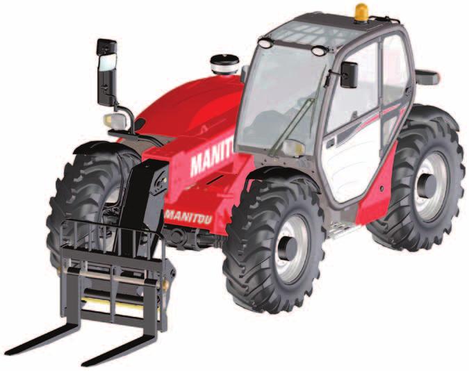
1 MANITOU BF BP ANCENIS CEDEX - FRANCE TEL: + 33 (0) YOUR DEALER EN (4/0/04) MT 73 ST3B MT 93 ST3B OPERATOR S MANUAL (ORIGINAL INSTRUCTIONS)
2
3 IMPORTANT Carefully read and understand this instruction manual before using the lift truck. It contains all information relating to operation, handling and lift truck equipment, as well as important recommendations to be followed. This document also contains precautions for use, as well as information on the servicing and routine maintenance required to ensure the lift truck's continued safety of use and reliability. WHENEVER YOU SEE THIS SYMBOL IT MEANS: WARNING! BE CAREFUL! YOUR SAFETY OR THE SAFETY OF THE LIFT TRUCK IS AT RISK. - This manual has been produced on the basis of the equipment list and the technical characteristics given at the time of its design. - The level of equipment of the lift truck depends on the options chosen and the country of sale. - According to the lift truck options and the date of sale, certain items of equipment/functions described herein may not be available. - Descriptions and figures are non binding. - MANITOU reserves the right to change its models and their equipment without being required to update this manual. - The MANITOU network, consisting exclusively of qualified professionals, is at your disposal to answer all your questions. - This manual is an integral part of the lift truck. - It is to be kept in its storage space at all times for ease of reference. - Hand this manual to the new owner if the lift truck is resold. 4/0/04 st DATE OF ISSUE THE TEXTS AND ILLUSTRATIONS IN THIS DOCUMENT MUST NOT BE REPRODUCED EITHER WHOLLY OR IN PART.
4 - OPERATING AND SAFETY INSTRUCTIONS - DESCRIPTION 3 - MAINTENANCE 4 - OPTIONAL ATTACHMENTS FOR USE WITH THE RANGE
5 - OPERATING AND SAFETY INSTRUCTIONS -
6 TABLE OF CONTENTS - OPERATING AND SAFETY INSTRUCTIONS INSTRUCTIONS TO THE COMPANY MANAGER 4 THE SITE 4 THE OPERATOR 4 THE LIFT TRUCK 4 A - THE TRUCK'S SUITABILITY FOR THE JOB B - ADAPTATION OF THE LIFT TRUCK TO STANDARD ENVIRONMENTAL CONDITIONS C - MODIFICATION OF THE LIFT TRUCK D - FRENCH ROAD TRAFFIC RULES E - LIFT TRUCK CAB PROTECTION THE INSTRUCTIONS 5 THE MAINTENANCE 5 INSTRUCTIONS FOR THE OPERATOR 6 PREAMBLE 6 GENERAL INSTRUCTIONS 6 A - OPERATOR'S MANUAL B - AUTHORISATION FOR USE IN FRANCE C - MAINTENANCE D - MODIFICATION OF THE LIFT TRUCK E - LIFTING PEOPLE OPERATING INSTRUCTIONS UNLADEN AND LADEN 7 A - BEFORE STARTING THE LIFT TRUCK B - DRIVER'S OPERATING INSTRUCTIONS C - ENVIRONMENT D - VISIBILITY E - STARTING THE LIFT TRUCK F - DRIVING THE LIFT TRUCK G - STOPPING THE LIFT TRUCK H - DRIVING THE LIFT TRUCK ON THE PUBLIC HIGHWAY INSTRUCTIONS FOR HANDLING A LOAD A - CHOICE OF ATTACHMENTS B - MASS OF LOAD AND CENTRE OF GRAVITY C - LONGITUDINAL STABILITY LIMITER AND WARNING DEVICE D - TRANSVERSE ATTITUDE OF THE LIFT TRUCK E - TAKING UP A LOAD ON THE GROUND F - TAKING UP AND LAYING A HIGH LOAD ON TYRES G - TAKING UP AND LAYING A HIGH LOAD ON STABILIZERS H - TAKING UP AND LAYING DOWN A SUSPENDED LOAD I - TRAVELLING WITH A SUSPENDED LOAD PLATFORM OPERATING INSTRUCTIONS 9 A - AUTHORISATION FOR USE B - LIFT TRUCK SUITABILITY FOR USE C - PRECAUTIONS WHEN USING THE PLATFORM D - USING THE PLATFORM E - ENVIRONMENT F - MAINTENANCE INSTRUCTIONS FOR USING THE RADIO-CONTROL HOW TO USE THE RADIO-CONTROL PROTECTIVE DEVICES LIFT TRUCK MAINTENANCE INSTRUCTIONS -
7 GENERAL INSTRUCTIONS PLACING THE JIB SAFETY WEDGE FITTING THE WEDGE REMOVING THE WEDGE MAINTENANCE MAINTENANCE LOGBOOK LUBRICANT AND FUEL LEVELS 3 HYDRAULIC 3 ELECTRICITY 3 WELDING 3 WASHING THE LIFT TRUCK 3 TRANSPORTING THE LIFT TRUCK 3 IF THE LIFT TRUCK IS NOT TO BE USED FOR A LONG TIME 4 INTRODUCTION 4 PREPARING THE LIFT TRUCK 4 PROTECTING THE ENGINE 4 PROTECTING THE LIFT TRUCK 4 BRINGING THE LIFT TRUCK BACK INTO SERVICE 5 LIFT TRUCK DISPOSAL 6 RECYCLING OF MATERIALS 6 METALS PLASTICS RUBBER GLASS ENVIRONMENTAL PROTECTION 6 WORN OR DAMAGED PARTS USED OIL USED BATTERIES
8 INSTRUCTIONS TO THE COMPANY MANAGER THE SITE Proper management of lift truck's area of travel will reduce the risk of accidents: ground not unnecessarily uneven or obstructed, no excessive slopes, pedestrian traffic controlled, etc. THE OPERATOR - Only qualified, authorized personnel can use the lift truck. This authorization is given in writing by the appropriate person in the establishment with respect to the use of lift trucks and must be carried permanently by the operator. Experience has shown that there are a number of inappropriate ways in which the lift truck might be used. Such foreseeable misuse, of which the main examples are listed below, are strictly forbidden. - The foreseeable abnormal behaviour resulting from ordinary negligence, but which does not result from any wish to put the machinery to any improper use. - The reflex reactions of a person in the event of a malfunction, incident, fault, etc. during operation of the lift truck. - Behaviour resulting from application of the "principle of least effort" when performing a task. - For certain machines, the foreseeable behaviour of such persons as: apprentices, teenagers, handicapped persons, trainees tempted to drive a lift truck, operators tempted to operate a truck for the purposes of a bet, a competition or for their own personal experience. The person in charge of the equipment must take these criteria into account when assessing the suitability of a person to drive. THE LIFT TRUCK A - THE TRUCK'S SUITABILITY FOR THE JOB - MANITOU has ensured that this lift truck is suitable for use under the standard operating conditions defined in this operator's manual, with a STATIC test coefficient OF,33 and a DYNAMIC test coefficient OF, as specified in harmonised standard EN 459 for variable range trucks. - Before commissioning, the company manager must make sure that the lift truck is appropriate for the work to be done, and perform certain tests (in accordance with current legislation). B - ADAPTATION OF THE LIFT TRUCK TO STANDARD ENVIRONMENTAL CONDITIONS - In addition to series equipment mounted on your lift truck, many options are available, such as: road lighting, stop lights, revolving light, reverse lights, reverse buzzer alarm, front light, rear light, light at the jib head, etc. (according to the lift truck model). - The operator must take into account the operating conditions to define the lift truck's signalling and lighting equipment. Contact your dealer. - Take into account climatic and atmospheric conditions of the site of utilisation. Protection against frost (see: 3 - MAINTENANCE: LUBRICANTS AND FUEL). Adaptation of lubricants (ask your dealer for information). Engine filtration (see: 3 - MAINTENANCE: FILTERS CARTRIDGES AND BELTS). For operation under average climatic conditions, i.e.: between -5 C and +35 C, correct levels of lubricants in all the circuits are checked in production. For operation under more severe climatic conditions, before starting up, it is necessary to drain all the circuits, then ensure correct levels of lubricants using lubricants properly suited to the relevant ambient temperatures. The same applies to the cooling liquid. - A lift truck operating in an area without fire extinguishing equipment must be equipped with an individual extinguisher. There are solutions, consult your dealer. Your lift truck is designed for outdoor use under normal atmospheric conditions and indoor use in suitably aerated and ventilated premises. It is prohibited to use the lift truck in areas where there is a risk of fire or which are potentially explosive (e.g. Refineries, fuel or gas depots, stores of flammable products, etc.). For use in these areas, specific equipment is available (ask your dealer for information). - Our trucks comply with Directive 004/08/EC concerning electromagnetic compatibility (EMC), and with the corresponding harmonized standard EN 895. Their proper operation is no longer guaranteed if they are used within areas in which the electromagnetic fields exceed the limit specified by that standard (0 V/m). - Directive 00/44/EC requires company managers to not expose their employees to excessive vibration doses. There is no recognized code of measurement for comparing the machines of different manufacturers. The actual doses received cannot therefore be measured under actual operating conditions at the user's premises. - The following are some tips for minimizing these vibration doses: Select the most suitable lift truck and attachment for the intended use. - 4
9 Adapt the seat adjustment to the operator's weight (according to lift truck model) and maintain it in good condition, as well as the cab suspension. Inflate the tires in accordance with recommendations. Ensure that the operators adapt their operating speed to suit the conditions on site. As far as possible, arrange the site in such a way as to provide a flat running surface and remove obstacles and harmful potholes. C - MODIFICATION OF THE LIFT TRUCK - For your safety and that of others, you must not change the structure and settings of the various components used in your lift truck (hydraulic pressure, calibrating limiters, engine speed, addition of extra equipment, addition of counterweight, unapproved attachments, alarm systems, etc.) yourself. In this event, the manufacturer cannot be held responsible. D - FRENCH ROAD TRAFFIC RULES (or see current legislation in other countries) - Only one certificate of conformity is issued. It must be kept in a safe place. - The driving of non EC type-approved tractors on the public highway is subject to the provisions of the highway code relating to special machines, defined in article R3- of the highway code, in category B of the Equipment Order of 0 November 969 that determines the procedures applicable to special machines. The lift truck must be fitted with a licence plate. - The driving of EC type-approved tractors on the public highway is subject to the provisions of the highway code regarding agricultural tractors, defined in article R3- of the highway code. The lift truck must be registered. SPECIAL INSTRUCTION APPLYING TO "EC TRACTOR" TYPE-APPROVED LIFT TRUCKS - All EC tractor type-approved lift trucks are supplied with an "EC tractor" certificate complying with directive 003/37/EC, to be retained by the owner, and a page of administrative details together with a CNIT number (national type approval code) for registration at the prefecture. - The lift truck owner is responsible for carrying out the necessary procedures for obtaining the vehicle registration document within the time limit defined by the regulations. - The operator must hold an HGV licence, unless granted an exemption. - The lift truck must be driven on the public highway in accordance with the instructions given in the manual supplied with the lift truck (Gross weight, Gross combination weight, towing load, axle loads, maximum speeds, etc. according to type/version). The operator must be in possession of the lift truck s registration document. When towing a trailer or agricultural equipment, the travelling speed of the lift truck is limited to 5 km/h. In this case, a "5" disc must be affixed to the rear of the convoy. E - LIFT TRUCK CAB PROTECTION - All lift trucks comply with the requirements of ISO 347 (wheel loader code) regarding cab rollover protection (ROPS) and ISO 3449 (Level II) regarding the protection of the cab against falling objects (FOPS). - "EC TRACTOR" type-approved lift trucks comply, in addition, with Directive 79/6/EC (OECD Code 4) regarding cab rollover protection (ROPS). Structural damage or overturning, a modification, changes or a poorly executed repair can reduce the protective efficiency of the cab, cancelling its compliance. Do not perform welding or drilling on the cab structure. Consult your dealer to determine the limits of this structure without cancelling its compliance. THE INSTRUCTIONS - The operator's manual must always be in good condition and kept in the place provided on the lift truck and in the language used by the operator. - The operator's manual and any plates or stickers which are no longer legible or are damaged, must be replaced immediately. THE MAINTENANCE - Maintenance or repairs other than those detailed in part: 3 - MAINTENANCE must be carried out by qualified personnel (consult your dealer) and under the necessary safety conditions to maintain the health of the operator and any third party. Your lift truck must be inspected periodically to ensure that it remains in compliance. The frequency of this inspection is defined by current legislation in the country in which the lift truck is used. - Example for France "The manager in charge of the establishment using a lift truck must open and maintain a maintenance log for each machine (order of March 004) and undergo a general periodic inspection every 6 months (order of March 004)". - 5
10 INSTRUCTIONS FOR THE OPERATOR PREAMBLE The risk of accident while using, servicing or repairing your lift truck can be restricted if you follow the safety instructions and safety measures detailed in these instruction. Failure to respect the safety and operating instructions, or the instructions for repairing or servicing your lift truck may lead to serious, even fatal accident. - Only the operations and manoeuvres described in these operator's manual must be performed. The manufacturer cannot predict all possible risky situations. Consequently, the safety instructions given in the operator's manual and on the lift truck itself are not exhaustive. - At any time, as an operator, you must envisage, within reason, the possible risk to yourself, to others or to the lift truck itself when you use it. In order to reduce or avoid any danger with a MANITOU-approved attachment, follow the instructions of paragraph: 4 - ADAPTABLE ATTACHMENTS IN OPTION ON THE RANGE: INTRODUCTION. GENERAL INSTRUCTIONS A - OPERATOR'S MANUAL - Read the operator's manual carefully. - The operator's manual must always be in good condition and in the place provided for it on the lift truck. - You must report any plates and stickers which are no longer legible or which are damaged. B - AUTHORISATION FOR USE IN FRANCE (or see current legislation in other countries). - Only qualified, authorized personnel can use the lift truck. This authorization is given in writing by the appropriate person in the establishment with respect to the use of lift trucks and must be carried permanently by the operator. - The operator is not competent to authorise the driving of the lift truck by another person. C - MAINTENANCE - The operator must immediately advise his superior if his lift truck is not in good working order or does not comply with the safety notice. - The operator is prohibited from carrying out any repairs or adjustments himself, unless he has been trained for this purpose. He must keep the lift truck properly cleaned if this is among his responsibilities. - The operator must carry out daily maintenance (see: 3 - MAINTENANCE: A - DAILY OR EVERY 0 HOURS SERVICE). - The operator must ensure tyres are adapted to the nature of the ground (see area of the contact surface of the tyres in the chapter: - DESCRIPTION: FRONT AND REAR TYRES). There are optional solutions, consult your dealer. SAND tyres. LAND tyres. Snow chains. Do not use the lift truck if the tyres are incorrectly inflated, damaged or excessively worn, because this could put your own safety or that of others at risk, or cause damage to the lift truck itself. The fitting of foam inflated tyres is prohibited and is not guaranteed by the manufacturer, excepting prior authorisation. D - MODIFICATION OF THE LIFT TRUCK - For your safety and that of others, you must not change the structure and settings of the various components used in your lift truck (hydraulic pressure, calibrating limiters, engine speed, addition of extra equipment, addition of counterweight, unapproved attachments, alarm systems, etc.) yourself. In this event, the manufacturer cannot be held responsible. - 6
11 E - LIFTING PEOPLE - The use of working equipment and load lifting attachments to lift people is: either forbidden or authorized exceptionally and under certain conditions (see current regulations in the country in which the lift truck is used). - The pictogram posted at the operator station reminds you that: Left-hand column It is forbidden to lift people, with any kind of attachment, using a non PLATFORM-fitted lift truck. Right-hand column With a PLATFORM-fitted lift truck, people can only be lifted using platforms designed by MANITOU for the purpose. - MANITOU sells equipment specifically designed for lifting people (OPTION PLATFORM lift truck, contact your dealer). OPERATING INSTRUCTIONS UNLADEN AND LADEN A - BEFORE STARTING THE LIFT TRUCK - Perform the daily service (see: 3 - MAINTENANCE: A - DAILY OR EVERY 0 HOURS SERVICE). - Make sure the lights, indicators and windscreen wipers are working properly. - Make sure the rear view mirrors are in good condition, clean and properly adjusted. - Make sure the horn works. B - DRIVER'S OPERATING INSTRUCTIONS - Whatever his experience, the operator is advised to familiarize himself with the position and operation of all the controls and instruments before operating the lift truck. - Wear clothes suited for driving the lift truck, avoid loose clothes. - Make sure you have the appropriate protective equipment for the job to be done. - Prolonged exposure to high noise levels may cause hearing problems. It is recommended to wear ear muffs to protect against excessive noise. - Always face the lift truck when getting into and leaving the driving seat and use the handle(s) provided for this purpose. Do not jump out of the seat to get down. - Always pay attention when using the lift truck. Do not listen to the radio or music using headphones or earphones. - Never operate the lift truck when hands or feet are wet or soiled with greasy substances. - For increased comfort, adjust the seat to your requirements and adopt the correct position in the driver s cab. Under no circumstances must the seat be adjusted while the lift truck is moving. - The operator must always be in his normal position in the driver s cab. It is prohibited to have arms or legs, or generally any part of the body, protruding from the driver s cab of the lift truck. - The safety belt must be worn and adjusted to the operator's size. - The control units must never in any event be used for any other than their intended purposes (e.g. climbing onto or down from the lift truck, portmanteau, etc.). - If the control components are fitted with a forced operation (lever lock) device, it is forbidden to leave the cab without first putting these controls in neutral. - It is prohibited to carry passengers either on the lift truck or in the cab. C - ENVIRONMENT - Comply with site safety regulations. - If you have to use the lift truck in a dark area or at night, make sure it is equipped with working lights. - During handling operations, make sure that no one is in the way of the lift truck and its load. - Do not allow anybody to come near the working area of the lift truck or pass beneath an elevated load. - When using the lift truck on a transverse slope, before lifting the boom, follow the instructions given in the paragraph: INSTRUCTIONS FOR HANDLING A LOAD: D - TRANSVERSE ATTITUDE OF THE LIFT TRUCK. - 7
12 - Travelling on a longitudinal slope: Drive and brake gently. Moving without load: Forks or attachment facing downhill. Moving with load: Forks or attachment facing uphill. - Take into account the lift truck s dimensions and its load before trying to negotiate a narrow or low passageway. - Never move onto a loading platform without having first checked: That it is suitably positioned and made fast. That the unit to which it is connected (wagon, lorry, etc.) will not shift. That this platform is prescribed for the total weight of the lift truck to be loaded. That this platform is prescribed for the size of the lift truck. - Never move onto a foot bridge, floor or freight lift, without being certain that they are prescribed for the weight and size of the lift truck to be loaded and without having checked that they are in sound working order. - Be careful in the area of loading bays, trenches, scaffolding, soft ground and manholes. - Make sure the ground is stable and firm under the wheels and/or stabilizers before lifting or removing the load. If necessary, add sufficient wedging under the stabilizers. - Make sure that the scaffolding, loading platform, pilings or ground is capable of bearing the load. - Never stack loads on uneven ground, they may tip over. If the load or the attachment must remain above a structure for a prolonged period of time, there is the risk that it will bear on the structure as the boom descends due to cooling of the oil in the cylinders. To eliminate this risk: - Regularly check the distance between the load or the attachment and the structure and readjust this if necessary. - If possible use the lift truck at an oil temperature as close as possible to ambient temperature. - When working near aerial lines, ensure that the safety distance is sufficient between the working area of the lift truck and the aerial line. You must consult your local electrical agency. You could be electrocuted or seriously injured if you operate or park the lift truck too close to power cables. In the event of high winds, do not carry out handling work that jeopardises the stability of the lift truck and its load, particularly if the load catches the wind badly. D - VISIBILITY - The safety of people within the lift truck's working area, as well as that of the lift truck itself and the operator are depend on good operator visibility of the lift truck's immediate vicinity in all situations and at all times. - This lift truck has been designed to allow good operator visibility (direct or indirect by means of rear-view mirrors) of the immediate vicinity of the lift truck while travelling with no load and with the boom in the transport position. - Special precautions must be taken if the size of the load restricts visibility towards the front: moving in reverse, site layout, assisted by a person directing the manoeuvre (while standing outside the truck's area of travel), making sure to keep this person clearly in view at all times, in any case, avoid reversing over long distances. - Certain special accessories may require the truck to travel with the boom in the raised position. In such cases, visibility on the right hand side is restricted, and special precautions must be taken: site layout, assisted by a person directing the manoeuvre (while standing outside the truck's area of travel). replacement of a suspended load by a load on a pallet. - If visibility of your road is inadequate, ask someone to assist by directing the manoeuvre (while standing outside the truck's area of travel), making sure to keep this person clearly in view at all times. - Keep all components affecting visibility in a clean, properly adjusted state and in good working order (e.g. windscreens, windows, windscreen wipers, windscreen washers, driving and work lights, rear-view mirrors). - 8
13 E - STARTING THE LIFT TRUCK SAFETY INSTRUCTIONS The lift truck must only be started up or manoeuvred when the operator is sitting in the driver s cab, with his seat belt adjusted and fastened. - Never try to start the lift truck by pushing or towing it. Such operation may cause severe damage to the transmission. If necessary, to tow the lift truck in an emergency, the transmission must be placed in the neutral position (see: 3 - MAINTENANCE: G - OCCASIONAL MAINTENANCE). - If using an emergency battery for start-up, use a battery with the same characteristics and respect battery polarity when connecting it. Connect at first the positive terminals before the negative terminals. Failure to respect polarity between batteries can cause serious damage to the electrical circuit. The electrolyte in the battery may produce an explosive gas. Avoid flames and generation of sparks close to the batteries. Never disconnect a battery while it is charging. INSTRUCTIONS - Check the closing and locking of the hood(s). - Check that the cab door is closed. - Check that the forward/reverse selector is in neutral, and that the parking brake is applied. - Press on the service brake pedal and maintain it down. - Turn the ignition key to the position I to activate the electrical and pre-heating system. - Whenever you switch on the lift truck, perform the automatic check on the longitudinal stability limiter and warning device (see: - DESCRIPTION: INSTRUMENTS AND CONTROLS). Do not use the lift truck if it does not conform to the regulations. - Check the fuel level on the indicator. - Turn the ignition key fully, the engine should then start. Release the ignition key and let the engine run at idle. - Do not engage the starter motor for more than 5 seconds and carry out the preheating between unsuccessful attempts. - Make sure all the signal lights on the control instrument panel are off. - Check all control instruments when the engine is warm and at regular intervals during use, so as to quickly detect any faults and to be able to correct them without any delay. - If an instrument does not show the correct display, stop the engine and immediately carry out the necessary operations. F - DRIVING THE LIFT TRUCK SAFETY INSTRUCTIONS The operators' attention is drawn to the risks involved in using the lift truck, in particular: - Risk of loosing control. - Risk of loosing lateral and frontal stability of the lift truck. The operator must remain in control of the lift truck. In the event of the lift truck overturning, do not try to leave the cabin during the incident. YOUR BEST PROTECTION IS TO STAY FASTENED IN THE CABIN. - Observe the company s traffic regulations or, by default, the public highway code. - Do not carry out operations which exceed the capacities of your lift truck or attachments. - Always drive the lift truck with the forks or attachment to the transport position, i.e. at 300 mm from the ground, the boom retracted and the carriage sloping backwards. - Only carry loads which are balanced and properly anchored to avoid any risk of a load falling off. - Ensure that palettes, cases, etc, are in good order and suitable for the load to be lifted. - Familiarise yourself with the lift truck on the terrain where it will be used. - Ensure that the service brakes are working properly. - The loaded lift truck must not travel at speeds in excess of km/h. - Drive smoothly at an appropriate speed for the operating conditions (land configuration, load on the lift truck). - Do not use the hydraulic boom controls when the lift truck is moving. - Never change the steering mode whilst driving. - Do not manoeuvre the lift truck with the boom in the raised position unless under exceptional circumstances and then with extreme caution, at very low speed and using gentle braking. Ensure that visibility is adequate. - Take bends slowly. - In all circumstances make sure you are in control of your speed. - On damp, slippery or uneven terrain, drive slowly. - Brake gently, never abruptly. - Only use the lift truck s forward/reverse selector from a stationary position and never do so abruptly. - Do not drive with your foot on the brake pedal. - Always remember that hydrostatic type steering is extremely sensitive to movement of the steering wheel, so turn it gently and not jerkily. - Never leave the engine on when the lift truck is unattended. - 9
14 - Do not leave the cab when the lift truck has a raised load. - Look where you are going and always make sure you have good visibility along the route. - Use the rear-view mirrors frequently. - Drive round obstacles. - Never drive on the edge of a ditch or steep slope. - It is dangerous to use two lift trucks simultaneously to handle heavy or bulky loads, since this operation requires particular precautions to be taken. It must only be used exceptionally and after risk analysis. - The ignition switch has an emergency stop mechanism in case of an operating anomaly occurring in the case of lift trucks not fitted with a punch-operated cut-out. INSTRUCTIONS - Always drive the lift truck with the forks or attachment to the transport position, i.e. at 300 mm from the ground, the boom retracted and the carriage sloping backwards. - For lift trucks with gearboxes, use the recommended gear (see: - DESCRIPTION: INSTRUMENTS AND CONTROLS). - Select the steering mode appropriate for its use and/or working conditions (see: - DESCRIPTION: INSTRUMENTS AND CONTROLS) (as model of lift truck). - Release the hand brake. - Shift the forward/reverse selector to the selected direction of travel and accelerate gradually until the lift truck moves off. Starting and driving a lift truck on a slope can present a very real danger. The lift truck being parked or stopped, scrupulously follow the following instructions for moving off: - Press the service brake pedal. - Engage st or nd gear and select forward or reverse. - Check that there is nothing and no-one obstructing the lift truck's path. - Release the service brake pedal and increase the engine revs. The risk is increased if the lift truck is laden or towing a trailer, requiring extreme vigilance. G - STOPPING THE LIFT TRUCK SAFETY INSTRUCTIONS - Never leave the ignition key in the lift truck during the operator's absence. - When the lift truck is stationary, or if the operator has to leave his cab (even for a moment), place the forks or attachment on the ground, apply the parking brake and place the forward/reverse selector in neutral. - Make sure that the lift truck is not stopped in any position that will interfere with the traffic flow and at less than one meter from the track of a railway. - In the event of prolonged parking on a site, protect the lift truck from bad weather, particularly from frost (check the level of antifreeze), close and lock all the lift truck accesses (doors, windows, cowls, etc.). INSTRUCTIONS - Park the lift truck on flat ground or on an incline lower than 5 %. - Set the forward/reverse selector to neutral. - Engage the parking brake. - For lift trucks with gearboxes, place the gear lever in neutral. - Fully retract the boom. - Lower the forks or attachment to rest on the ground. - When using an attachment with a grab or jaws, or a bucket with hydraulic opening, close the attachment fully. - Before stopping the lift truck after a long working period, leave the engine idling for a few moments, to allow the coolant liquid and oil to lower the temperature of the engine and transmission. Do not forget this precaution, in the event of frequent stops or warm stalling of the engine, or else the temperature of certain parts will rise significantly due to the stopping of the cooling system, with the risk of badly damaging such parts. - Stop the engine with the ignition switch. - Remove the ignition key. - Lock all the accesses to the lift truck (doors, windows, cowls ). - 0
15 H - DRIVING THE LIFT TRUCK ON THE PUBLIC HIGHWAY (or see current legislation in other countries) FRENCH ROAD TRAFFIC RULES - The driving of non EC type-approved tractors on the public highway is subject to the provisions of the highway code relating to special machines, defined in article R3- of the highway code, in category B of the Equipment Order of 0 November 969 that determines the procedures applicable to special machines. The lift truck must be fitted with a licence plate. - The driving of EC type-approved tractors on the public highway is subject to the provisions of the highway code regarding agricultural tractors, defined in article R3- of the highway code. The lift truck must be registered. - The lift truck must be driven on the public highway in accordance with the instructions given in the manual supplied with the lift truck (Gross weight, Gross combination weight, towing load, axle loads, maximum speeds, etc. according to type/version). The operator must be in possession of the lift truck s registration document. - The operator must hold an HGV licence, unless granted an exemption. - When towing a trailer or agricultural equipment, the travelling speed of the lift truck is limited to 5 km/h. In this case, a "5" disc must be affixed to the rear of the convoy. When driving with a trailer, the fact of not engaging 4th gear will ensure compliance with the towing speed limit (max. 5 km/h). On "POWERSHIFT" models, as 3rd gear is slower than on other models, it is preferable to use 5th gear and disable automatic upshifting to 6th gear (see: - DESCRIPTION: INSTRUMENTS AND CONTROLS). SAFETY INSTRUCTIONS - Operators driving on the public highway must comply with current highway code legislation. - The lift truck must comply with current road legislation. If necessary, there are optional solutions. Contact your dealer. INSTRUCTIONS - Make sure the revolving light is in place, switch it on and verify its operation. - Make sure the lights, indicators and windscreen wipers are working properly. - Switch off the working headlights if the lift truck is fitted with them. - Select the steering mode "HIGHWAY TRAFFIC" (as model of lift truck) (see: - DESCRIPTION: INSTRUMENTS AND CONTROLS). - Fully retract the boom and set the attachment approximately 300 mm off the ground. - Place the roll corrector in the central position, i.e. the transverse axis of the axles parallel to the chassis (as model of lift truck). - Fully raise the stabilizers and turn the blocks inwards (according to model of lift truck). Never coast in neutral (forward/reverse selector or gear lever in neutral or transmission cut-off button pressed) to preserve the lift truck engine brake. Failure to observe this instruction on a slope will lead to excessive speed which may make the lift truck uncontrollable (steering, brakes) and cause serious mechanical damage. DRIVING THE LIFT TRUCK WITH A FRONT-MOUNTED ATTACHMENT - You must comply with current regulations in your country, covering the possibility of driving on the public highway with a front-mounted attachment on your lift truck. - If road legislation in your country authorizes circulation with a front-mounted attachment, you must at least: Protect and report any sharp and/or dangerous edges on the attachment (see: 4 - ADAPTABLE ATTACHMENTS IN OPTION ON THE RANGE: ATTACHMENT SHIELDS). The attachment must not be loaded. Make sure that the attachment does not mask the lighting range of the forward lights. Make sure that current legislation in your country does not require other obligations. OPERATING THE LIFT TRUCK WITH A TRAILER - For using a trailer, observe the regulations in force in your country (maximum travel speed, braking, maximum weight of trailer, etc.). - Do not forget to connect the trailer s electrical equipment to that of the lift truck. - The trailer's braking system must comply with current legislation. - If pulling a trailer with assisted braking, the tractor lift truck must be equipped with a trailer braking mechanism. In this case, do not forget to connect the trailer braking equipment to the lift truck. - The vertical force on the towing hook must not exceed the maximum authorised by the manufacturer (consult the manufacturer s plate on your lift truck). - The authorised gross vehicle weight must not exceed the maximum weight authorised by the manufacturer (see: - DESCRIPTION: CHARACTERISTICS). IF NECESSARY, CONSULT YOUR DEALER. -
16 INSTRUCTIONS FOR HANDLING A LOAD A - CHOICE OF ATTACHMENTS - Only attachments approved by MANITOU can be used on its lift trucks. - Make sure the attachment is appropriate for the work to be done (see: 4 - ADAPTABLE ATTACHMENTS IN OPTION ON THE RANGE). - If the lift truck is equipped with the Single side-shift carriage OPTION (TSDL), use only the authorised attachments (see: 4 - ADAPTABLE ATTACHMENTS IN OPTION ON THE RANGE). - Make sure the attachment is correctly installed and locked onto the lift truck carriage. - Make sure that your lift truck attachments work properly. - Comply with the load chart limits for the lift truck for the attachment used. - Do not exceed the rated capacity of the attachment. - Never lift a load in a sling without the attachment provided for the purpose, as the sling risks to slip (see: INSTRUCTIONS FOR HANDLING A LOAD: H - TAKING UP AND LAYING DOWN A SUSPENDED LOAD). - Do not handle loads that are hung directly from the forks with straps (e.g.: big-bag), as there is a risk that the straps will shear against the sharp edges. Use an attachment designed for this purpose. B - MASS OF LOAD AND CENTRE OF GRAVITY - Before taking up a load, you must know its mass and its centre of gravity. - The load chart for your lift truck is valid for a load in which the longitudinal position of the centre of gravity is 500 mm from the base of the forks (fig. B). For a higher centre of gravity, contact your dealer. - For irregular loads, determine the transverse centre of gravity before any movement (fig. B) and set it in the longitudinal axis of the lift truck. It is forbidden to move a load heavier than the effective capacity defined on the lift truck load chart. For loads with a moving centre of gravity (e.g. liquids), take account of the variations in the centre of gravity in order to determine the load to be handled and be vigilant and take extra care to limit these variations as far as possible. 500 mm B B C - LONGITUDINAL STABILITY LIMITER AND WARNING DEVICE This device gives an indication of the longitudinal stability of the lift truck, and limits hydraulic movements in order to ensure this stability, at least under the following operating conditions: when the lift truck is at a standstill, when the lift truck is on firm, stable and consolidated ground, when the lift truck is performing handling and placing operations. - Move the jib very carefully when approaching the authorized load limit (see: - DESCRIPTION: INSTRUMENTS AND CONTROLS). - Always watch this device during handling operations. - In the event that "AGGRAVATING" hydraulic movements are cut-off, only perform de-aggravating hydraulic movements in the following order (fig. C): if necessary, raise the jib (), retract the jib as far as possible () and lower the jib (3) to set down the load. The instrument reading may be erroneous when the steering is at full lock or the rear axle is oscillated to its maximum extent. Before lifting a load, make sure that the lift truck is not in either of these situations. 3 C -
17 D - TRANSVERSE ATTITUDE OF THE LIFT TRUCK Depending on the model of lift truck The transverse attitude is the transverse slope of the chassis with respect to the horizontal. Raising the jib reduces the lift truck's lateral stability. The transverse attitude must be set with the jib in down position as follows: - LIFT TRUCK WITHOUT ROLL CORRECTOR USED ON TYRES - Position the lift truck so that the bubble in the level is between the two lines (see: - DESCRIPTION: INSTRUMENTS AND CONTROLS). - LIFT TRUCK WITH ROLL CORRECTOR USED ON TYRES - Correct the roll using the hydraulic control and check horizontality with the spirit level. The bubble in the level must be between the two lines (see: - DESCRIPTION: INSTRUMENTS AND CONTROLS). 3 - LIFT TRUCK USED ON STABILIZERS D - Set the two stabilizers on the ground and raise the two front wheels of the lift truck (fig. D). - Correct the roll using the stabilizers (fig. D) and check horizontality with the spirit level. The bubble of the level must be between the two lines (see: - DESCRIPTION: INSTRUMENTS AND CONTROLS). In this position, the two front wheels must be off the ground. D E - TAKING UP A LOAD ON THE GROUND - Approach the lift truck perpendicular to the load, with the jib retracted and the forks in a horizontal position (fig. E). - Adjust the fork spread and centring relative to the load to ensure stability (fig. E) (optional solutions exist, consult your dealer). - Never lift a load with a single fork. Beware of the risks of trapping or squashing limbs when manually adjusting the forks. - Move the lift truck forward slowly () and insert the forks under the load as far as they will go (fig. E3). If necessary, slightly lift the jib () while taking up the load. - Bring the load into the transport position. - Tilt the load far enough backwards to ensure stability (loss of load on braking or going downhill). FOR A NON-PALLETISED LOAD - Tilt the carriage () forwards and move the lift truck slowly forwards (), to insert the fork under the load (fig. E4) (block the load if necessary). - Continue to move the lift truck forwards () tilting the carriage (3) (fig. E4) backwards to position the load on the forks and check the load's longitudinal and lateral stability. E E E3 E4 3-3
18 F - TAKING UP AND LAYING A HIGH LOAD ON TYRES You must not raise the jib if you have not checked the transverse attitude of the lift truck (see: INSTRUCTIONS FOR HANDLING A LOAD: D - TRANSVERSE ATTITUDE OF THE LIFT TRUCK). F REMINDER: Make sure that the following operations can be performed with good visibility (see: OPERATIONS INSTRUCTIONS UNLADEN AND LADEN: D - VISIBILITY). TAKING UP A HIGH LOAD ON TYRES - Ensure that the forks will easily pass under the load. - Lift and extend the jib () () until the forks are level with the load, moving the lift truck (3) forward if necessary (fig. F), moving very slowly and carefully. - Always remember to keep the distance necessary for inserting the forks under the load, between the stack and the lift truck (fig. F) and use the shortest possible length of jib. - Insert the forks under the load as far as they will go by alternately extending and lowering the jib () or, if necessary, moving the lift truck forward () (fig. F). Apply the handbrake and place the forward/reverse selector in neutral. - Slightly raise the load () and tilt the carriage () backwards to stabilize the load (fig. F3). - Tilt the load sufficiently backwards to ensure its stability. - Monitor the longitudinal stability limiter and warning device (see: INSTRUCTIONS FOR HANDLING A LOAD: C - LONGITUDINAL STABILITY LIMITER AND WARNING DEVICE). If it is overloaded, set the load back down in the place from which it was taken. - If possible lower the load without shifting the lift truck. Lift the jib () to release the load, retract () and lower the jib (3) to bring the load into the transport position (fig. F4). - If this is not possible, back up the lift truck (), manoeuvring very gently and carefully to release the load. Retract () and lower the jib (3) to bring the load into the transport position (fig. F5). 3 F F3 F4 3 F5 3-4
19 LAYING A HIGH LOAD ON TYRES - Approach the load in the transport position in front of the stack (fig. F6). - Apply the parking brake and place the forward/reverse selector in neutral. - Raise and extend the jib () () until the load is above the stack, while monitoring the longitudinal stability limiter and warning device (see: INSTRUCTIONS FOR HANDLING A LOAD: C - LONGITUDINAL STABILITY LIMITER AND WARNING DEVICE). If necessary, move the lift truck (3) forward (fig. F7), driving very slowly and carefully. - Place the load in a horizontal position and lay it down on the pile by lowering and retracting the jib () () in order to position the load correctly (fig. F8). - If possible, release the fork by alternately retracting and raising the jib () (fig. F9). Then set the forks into transport position. - If this is not possible, reverse the lift truck () very slowly and carefully to release the forks (fig. F0). Then set them into transport position. F6 F7 3 F8 F9 F0-5
20 G - TAKING UP AND LAYING A HIGH LOAD ON STABILIZERS Depending on the model of lift truck You must not raise the jib if you have not checked the transverse attitude of the lift truck (see: INSTRUCTIONS FOR HANDLING A LOAD: D - TRANSVERSE ATTITUDE OF THE LIFT TRUCK). REMINDER: Make sure that the following operations can be performed with good visibility (see: OPERATIONS INSTRUCTIONS UNLADEN AND LADEN: D - VISIBILITY). The stabilizers are used to optimise the lift truck's lifting performances (see: - DESCRIPTION: INSTRUMENTS AND CONTROLS). POSITION THE STABILIZERS WITH THE FORKS IN TRANSPORT POSITION (UNLADEN AND G LADEN) - Set the forks in transport position in front of the elevation. - Stay far enough away to have room for the jib to be raised. - Apply the parking brake and place the forward/reverse selector in neutral. - Set the two stabilizers on the ground and lift the two front wheels of the lift truck (fig. G), while maintaining its transverse stability. RAISE THE STABILIZERS WITH THE FORKS IN TRANSPORT POSITION (UNLADEN AND LADEN) - Raise both stabilizers fully and at the same time. LOWERING OF STABILISERS WITH JIB UP (UNLADEN AND LADEN). This operation must be exceptional and performed with great care. - Raise the jib and retract the telescopes completely. - Set the lift truck in position in front of the elevation (fig. G) moving very slowly and carefully. - Apply the parking brake and place the forward/reverse selector in neutral. - Move the stabilizers very slowly and gradually as soon as they are close to the ground or in contact with it. - Lower the two stabilizers and lift the two front wheels of the lift truck (fig. G3). During this operation, transverse attitude must be permanently maintained: the bubble in the level must be kept between the two lines. SETTING THE STABILIZERS WITH THE JIB UP (UNLADEN AND LADEN) This operation must be exceptional and performed with great care. - Keep the jib up and retract the telescopes completely (fig. G3). - Move the stabilizers very slowly and gradually as soon as they are in contact with the ground and when they leave the ground. During this operation, the transverse attitude must be permanently maintained: the bubble in the level must be kept between the two lines. - Raise both stabilizers completely. - Release the parking brake and reverse the lift truck () very slowly and carefully, to release it and lower the forks () into transport position (fig. G4). G G3 G4-6
21 TAKING UP A HIGH LOAD ON STABILISERS - Ensure that the forks will easily pass under the load. - Check the position of the lift truck with respect to the load and make a test run, if necessary, without taking the load. - Raise and extend the jib () () until the forks are at the level of the load (fig. G5). - Insert the forks under the load as far as they will go by alternately extending and lowering the jib () (fig. G6). - Lift the load slightly () and tilt the carriage () backwards to stabilise the load (fig. G7). - Monitor the longitudinal stability limiter and warning device (see: INSTRUCTIONS FOR HANDLING A LOAD: C - LONGITUDINAL STABILITY LIMITER AND WARNING DEVICE). If it is overloaded, set the load back down in the place from which it was taken. - If possible lower the load without moving the lift truck. Raise the jib () to release the load, retract () and lower the jib (3) to set the load into transport position (fig. G8). G5 G6 G7 G8 3 LAYING A HIGH LOAD ON STABILISERS - Raise and extend the jib () () until the load is above the elevation (fig. G9), while monitoring the longitudinal stability limiter and warning device (see: INSTRUCTIONS FOR HANDLING A LOAD: C - LONGITUDINAL STABILITY LIMITER AND WARNING DEVICE). - Position the load horizontally and release it by lowering and retracting the jib () () to position the load correctly (fig. G0). - Free the forks by alternating retracting and raising the jib (3) (fig. G). - If possible, set the jib in transport position without moving the lift truck. G9 G0 G 3-7
22 H - TAKING UP AND LAYING DOWN A SUSPENDED LOAD Failure to follow the above instructions may lead the lift truck to loose stability and overturn. MUST be used with a lift truck equipped with an operational hydraulic movement cut-out device. CONDITIONS OF USE - The length of the sling or the chain shall be as short as possible to limit swinging of the load. - Lift the load vertically along its axis, never by pulling sideways or lengthways. HANDLING WITHOUT MOVING THE LIFT TRUCK - Whether on stabilisers or on tyres, the lateral attitude must not exceed % and the longitudinal attitude must not exceed 5%, the bubble of the level must be held at "0". - Ensure that the wind speed is not higher than 0 m/s. - Ensure that there is no one between the load and the lift truck. I - TRAVELLING WITH A SUSPENDED LOAD - Before moving, inspect the terrain in order to avoid excessive slopes and cross-falls, bumps and potholes, or soft ground. - Ensure that the wind speed is not higher than 36 km/h. - The lift truck must not travel at more than 0,4 m/s (,5 km/h, i.e., one quarter walking speed). - Drive and stop the lift truck gently and smoothly to minimise swinging of the load. - Carry the load a few centimetres above the ground (max. 30 cm) the shortest possible jib length. Do not exceed the offset indicated on the load chart. If the load begins to swing excessively, do not hesitate to stop and lower the jib to set down the load. - Before moving the lift truck, check the longitudinal stability limiter and warning device (see: - DESCRIPTION: INSTRUMENTS AND CONTROLS), only the green LEDs and possible the yellow LEDs should be lit. - During transport, the lift truck operator must be assisted by a person on the ground (standing a minimum of 3 m from the load), who will limit swinging of the load using a bar or a rope. Ensure that this person is always clearly in view. - The lateral attitude must not exceed 5 %, the bubble in the level must be kept between the two "MAX" marks - The longitudinal attitude must not exceed 5 %, with the load facing uphill, and 0%, with the load facing downhill. - The jib angle must not exceed If the first red LED of longitudinal stability limiter and warning device (see: - DESCRIPTION: INSTRUMENTS AND CONTROLS) comes on while travelling, gently bring the lift truck to a halt and stabilise the load. Retract the telescope to reduce the offset of the load. - 8
23 PLATFORM OPERATING INSTRUCTIONS For lift trucks fitted with a PLATFORM Installation of the platform on the lift truck is only possible if the shields "operating the platform" of the lift truck and the platform are identical (see: - DESCRIPTION: OPERATING THE PLATFORM). A - AUTHORISATION FOR USE - Operation of the platform requires further authorisation in addition to that of the lift truck. B - LIFT TRUCK SUITABILITY FOR USE - MANITOU has ensured that this platform is suitable for use under the normal operating conditions defined in this operator's manual, with a STATIC test coefficient OF,5 and a DYNAMIC test coefficient OF,, as specified in harmonised standard EN 80 for "mobile elevating work platforms". - Before commissioning, the company manager must make sure that platform is appropriate for the work to be done, and perform certain tests (in accordance with current legislation). C - PRECAUTIONS WHEN USING THE PLATFORM - Wear suitable clothing when using the platform, avoid loosely-fitting garments. - Never operate the platform when hands or feet are wet or soiled with greasy substances. - Remain alert at all times when using the platform. Do not listen to the radio or music using headphones or earphones. - For increased comfort, adopt the correct position at the platform's operator station. - The platform's guard rail exempts the operator from wearing a safety harness under normal operating conditions. As a result, you are responsible for deciding whether to wear a safety harness. - The control units must never in any event be used for any other than their intended purposes (e.g. climbing onto or down from the lift truck, portmanteau, etc.). - Safety helmets must be worn. - The operator must always be in the normal operator's position. It is prohibited to have arms or legs, or generally any part of the body, protruding from the basket. - Ensure that any materials loaded onto the platform (pipes, cables, containers, etc.) cannot fall out. Do not pile these materials to the point where it is necessary to step over them. D - USING THE PLATFORM - However experienced they may be, operators must acquaint themselves with the emplacement and operation of all control instruments prior to operating the platform. - Check before use that the platform has been correctly assembled and locked onto the lift truck. - Check before operating the platform that the access gate has been properly locked. - The platform should be operated in an area free of any obstructions or danger when it is lowered to the ground. - The operator using the platform must be aided on the ground by a person with adequate training. - You should stay within the limits set out in the platform load chart. - The lateral stresses are limited pressure (see: - DESCRIPTION: CHARACTERISTICS). - It is strictly forbidden to hang a load from the platform or the lift truck jib without a specially designed attachment (see: INSTRUCTIONS FOR HANDLING A LOAD: H - TAKING UP AND LAYING DOWN A SUSPENDED LOAD). - The platform cannot be used as a crane or a lift for permanently transporting people or materials, nor as jacks or supports. - The lift truck must not be moved with one (or more) person(s) in the platform. - It is forbidden to transport people on the platform using the hydraulic controls in the lift truck s driver s cab (except in case of rescue). - The operator must not climb onto to off the platform when it is not on ground level (jib retracted and in the down position). - The platform must not be fitted with attachments that increase the unit's wind load. - Do not use ladders or improvised structures in the platform to gain extra height. - Do not climb onto the sides of the platform to gain extra height. E - ENVIRONMENT It is forbidden to use the platform close to electricity cables. Maintain the specified safe distances. RATED VOLTAGE DISTANCE ABOVE GROUND OR FLOOR IN METRES 50 < U < 000,30 M 000 < U < 30000,50 M < U < 45000,60 M < U < 63000,80 M < U < ,00 M < U < ,40 M < U < ,00 M 5000 < U < ,30 M < U < ,90 M - 9
24 It is strictly forbidden to use the platform when the wind speed exceeds 45 km/h. - To visually recognise this wind speed, refer to the empirical wind evaluation scale below: BEAUFORT scale (wind speed at a height of 0 m on a flat site) Speed Speed Speed Force Type of wind Effects on Land (knots) (km/h) (m/s) 0 Calm < 0,3 - Smoke rises vertically. Light air ,3 -,5 Light breeze ,6-3,3 3 Gentle breeze ,4-5,4 4 Moderate breeze ,5-7,9 5 Fresh breeze ,7 6 Strong breeze ,8-3,8 7 Near gale ,9-7, 8 Gale , - 0,7 9 Strong gale ,8-4,4 0 Storm ,5-8,4 Violent storm ,5-3,6 Hurricane ,7 + - Smoke indicates direction of wind. - Wind felt on face, leaves rustle. - Leaves and small twigs in constant motion. - Wind raises dust and loose pieces of paper; small branches are moved. - Small tees in leaf begin to sway. - Large branches in motion, whistling heard in overhead wires, umbrella use becomes difficult. - Whole trees in motion, inconvenience felt when walking against the wind. - Wind breaks twigs off trees; impedes progress. - Wind damages roofs (chimneys, slates, etc.). - Seldom experienced inland; trees uprooted; considerable structural damage occurs. - Very rare, widespread damage. - Devastating damage. Sea conditions - Sea is like a mirror. - Ripples with appearance of scale, no foam crests. - Short wavelets, but pronounced. - Very small waves, crests begin to break. - Small waves, becoming longer, numerous whitecaps. - Wavelets form on inland waters; moderate waves, taking longer form. - Larger waves forming, whitecaps everywhere, some spray. - Sea heaps up; white foam from breaking waves begins to be blown in streaks along the direction of the wind. - Moderately high waves of greater length; edges of crests begin to break into spindrift. - High waves, crests of waves begin to topple, streaks of foam; reduced visibility. - Very high waves; white streaks of foam; reduced visibility. - Exceptionally high waves able to hide medium sized ships from view, reduced visibility. - Sea completely white; air filled with foam and spray, very reduced visibility. F - MAINTENANCE Your platform must be periodically inspected to ensure its continued compliance. The inspection frequency is defined by the legislation applying in the country in which the platform is used. In France, a general periodic inspection every 6 months (order of March 004). - 0
25 INSTRUCTIONS FOR USING THE RADIO-CONTROL For lift trucks with RC radio control HOW TO USE THE RADIO-CONTROL SAFETY INSTRUCTIONS - This radio-control consists of electronic and mechanical safety elements. It cannot receive commands from another transmitter because the internal encoding is unique to each radio-control. If it is used improperly or incorrectly, there is a risk of danger to: - The physical and mental health of the user or others. - The lift truck and other neighbouring items. All those working with this radio-control: - Must be qualified in line with current regulations and trained accordingly. - Must follow this instruction manual as closely as possible. - The system is used to control the lift truck remotely via radio waves. Commands are also transmitted if the lift truck is out of sight (behind an obstacle or a building for example), this is why: After stopping the truck and removing the key switch (only possible when it is stationary), always place the transmitter in a safe, dry place. Before performing any installation, servicing or repair work, always switch off power sources (in particular, electric welding devices and electric head units on hydraulic distributors must be disconnected at each section). Never remove or alter the safety devices (such as the hand-guard frame, key, emergency stop button, etc.). Never drive the lift truck if it is not continuously and perfectly within view of the operator! - Before leaving the transmitter, the operator must make sure that it cannot be used by an unauthorized third person: either by removing the key button from the transmitter or locking it in an inaccessible place. - The user must ensure that the instruction manual is accessible at all times and that operators have read and understood it. INSTRUCTIONS - Take up position in a stable place with no risk of slipping. - Before using the transmitter, make sure there is nobody within the working area. - Only use the transmitter with its carrying device or installed correctly on the platform. When you remove the transmitter, remove the accumulator and key button so that it cannot be used accidentally or deliberately by anyone else. PROTECTIVE DEVICES - The lift truck will be immobilised within a maximum of 450 milliseconds (approx. 0.5 second): If the emergency stop button of the transmitter is pressed (50 milliseconds), or that of the lift truck. If the transmission distance of the radio waves is exceeded. If the transmitter is faulty. If an interfering radio signal is received from elsewhere. If the accumulator is removed from its housing in the transmitter. If the battery reaches the end of its autonomy. If the transmitter is switched off by turning the key switch to the off position. - These protective devices are provided for the safety of personnel and property and must never be altered, removed or bypassed in any way whatsoever! - The hand-guard frame prevents external action on a manipulator (e.g. if the transmitter is dropped, or if the operator leans on a guard-rail). - An electronic safety device prevents radio transmission from being initiated if the manipulators are not mechanically and electrically at rest and if the internal combustion engine speed selector is not set to idle. In an emergency, press the transmitter emergency stop button immediately ; then follow the manual's instructions (see: - DESCRIPTION: INSTRUMENTS AND CONTROLS). -
26 LIFT TRUCK MAINTENANCE INSTRUCTIONS GENERAL INSTRUCTIONS - Ensure the area is sufficiently ventilated before starting the lift truck. - Wear clothes suitable for the maintenance of the lift truck, avoid wearing jewellery and loose clothes. Tie and protect your hair, if necessary. - Stop the engine and remove the ignition key, when an intervention is necessary. - Read the operator's manual carefully. - Carry out all repairs immediately, even if the repairs concerned are minor. - Repair all leaks immediately, even if the leak concerned is minor. - Make sure that the disposal of process materials and of spare parts is carried out in total safety and in a ecological way. - Be careful of the risk of burning and splashing (exhaust, radiator, engine, etc.). PLACING THE JIB SAFETY WEDGE - The lift truck is equipped with a jib safety wedge (see: - DESCRIPTION: INSTRUMENTS AND CONTROLS) that must be installed on the rod of the lifting cylinder when working beneath the jib. FITTING THE WEDGE - Fully raise the jib. - Place the safety wedge on the rod of the lifting cylinder and secure with the rod and the pin 3. - Slowly lower the jib then stop the hydraulic movements before it comes into contact with the wedge. REMOVING THE WEDGE - Fully raise the jib. - Remove the pin and the rod. - Return the safety wedge to the storage location provided on the lift truck. Only use the wedge supplied with the lift truck. 3 MAINTENANCE - Perform the periodic service (see: 3 - MAINTENANCE) to keep your lift truck in good working conditions. Failure to perform the periodic service may cancel the contractual guarantee. MAINTENANCE LOGBOOK - The maintenance operations carried out in accordance with the recommendations given in part: 3 - MAINTENANCE and the other inspection, servicing or repair operations or modifications performed on the lift truck or its attachments shall be recorded in a maintenance logbook. The entry for each operation shall include details of the date of the works, the names of the individuals or companies having performed them, the type of operation and its frequency, if applicable. The part numbers of any lift truck items replaced shall also be indicated. -
27 LUBRICANT AND FUEL LEVELS - Use the recommended lubricants (never use contaminated lubricants). - Do not fill the fuel tank when the engine is running. - Only fill up the fuel tank in areas specified for this purpose. - Do not fill the fuel tank to the maximum level. - Do not smoke or approach the lift truck with a flame, when the fuel tank is open or is being filled. HYDRAULIC - Any work on the load handling hydraulic circuit is forbidden except for the operations described in part: 3 - MAINTENANCE. - Do not attempt to loosen unions, hoses or any hydraulic component with the circuit under pressure. BALANCING VALVE: It is dangerous to change the setting and remove the balancing valves or safety valves which may be fitted to your lift truck cylinders. The HYDRAULIC ACCUMULATORS that may be fitted on your lift truck are pressurised units. Removing these accumulators and their pipework is a dangerous operation and must only be performed by approved personnel (consult your dealer). ELECTRICITY - Do not short-circuit the starter relay to start the engine. If the forward/reverse selector is not in neutral and the parking brake is not applied, the lift truck may suddenly start to move. - Do not drop metallic items on the battery. - Disconnect the battery before working on the electrical circuit. WELDING - Disconnect the battery before any welding operations on the lift truck. - When carrying out electric welding work on the lift truck, connect the negative cable from the equipment directly to the part being welded, so as to avoid high tension current passing through the alternator. - Never carry out welding or work which gives off heat on an assembled tyre. The heat would increase the pressure which could cause the tyre to explode. - If the lift truck is equipped with an electronic control unit, disconnect this before starting to weld, to avoid the risk of causing irreparable damage to electronic components. WASHING THE LIFT TRUCK - Clean the lift truck or at least the area concerned before any intervention. - Remember to close and lock all accesses to the lift truck (doors, windows, cowls ). - During washing, avoid the articulations and electrical components and connections. - If necessary, protect against penetration of water, steam or cleaning agents, components susceptible of being damaged, particularly electrical components and connections and the injection pump. - Clean the lift truck of any fuel, oil or grease trace. TRANSPORTING THE LIFT TRUCK Transporting the lift truck involves real risks for the operator and others involved. - Towing, slinging or transporting the lift truck (see: 3 - MAINTENANCE: G - OCCASIONAL MAINTENANCE). - 3
28 IF THE LIFT TRUCK IS NOT TO BE USED FOR A LONG TIME INTRODUCTION The following recommendations are intended to prevent the lift truck from being damaged when it is withdrawn from service for an extended period. For these operations, we recommend the use of a MANITOU protective product, reference Instructions for using the product are given on the packaging. Procedures to follow if the lift truck is not to be used for a long time and for starting it up again afterwards must be performed by your dealership. PREPARING THE LIFT TRUCK - Clean the lift truck thoroughly. - Check and repair any fuel, oil, water or air leaks. - Replace or repair any worn or damaged parts. - Wash the painted surfaces of the lift truck in clear and cold water and wipe them. - Touch up the paintwork if necessary. - Shut down the lift truck (see: OPERATING INSTRUCTIONS UNLADEN AND LADEN). - Make sure the jib cylinder rods are all in retracted position. - Release the pressure in the hydraulic circuits. PROTECTING THE ENGINE - Fill the tank with fuel (see: 3 - MAINTENANCE: A - DAILY OR EVERY 0 HOURS SERVICE). - Empty and replace the cooling liquid (see: 3 - MAINTENANCE: F - EVERY 000 HOURS SERVICE). - Leave the engine running at idling speed for a few minutes, then switch off. - Replace the engine oil and oil filter (see: 3 - MAINTENANCE: D - EVERY 500 HOURS SERVICE). - Add the protective product to the engine oil. - Run the engine for a short time so that the oil and cooling liquid circulate inside. - Disconnect the battery and store it in a safe place away from the cold, after charging it to a maximum. - Remove the injectors and spray the protective product into each cylinder for two seconds with the piston in low neutral position. - Turn the crankshaft once slowly and refit the injectors (see engine REPAIR MANUAL). - Remove the intake hose from the manifold or turbocharger and spray the protective product into the manifold or turbocharger. - Cap the intake manifold or turbocharger hole with waterproof adhesive tape. - Remove the exhaust pipe and spray the protective product into the exhaust manifold or turbocharger. - Refit the exhaust pipe and block the outlet with waterproof adhesive tape. NOTE: The spray time is noted on the product packaging and must be increased by 50 % for turbo engines. - Open the filler plug, spray the protective product around the rocker arm shaft and refit the filler plug. - Cap the fuel tank using waterproof adhesive tape. - Remove the drive belts and store them in a safe place. - Disconnect the engine cut-off solenoid on the injection pump and carefully insulate the connection. PROTECTING THE LIFT TRUCK - Set the lift truck on axle stands so that the tyres are not in contact with the ground and release the handbrake. - Protect cylinder rods which will not be retracted, from corrosion. - Wrap the tyres. NOTE: If the lift truck is to be stored outdoors, cover it with a waterproof tarpaulin. - 4
29 BRINGING THE LIFT TRUCK BACK INTO SERVICE - Remove the waterproof adhesive tape from all the holes. - Refit the intake hose. - Refit and reconnect the battery. - Remove the protection from the cylinder rods. - Perform the daily service (see: 3 - MAINTENANCE: A - DAILY OR EVERY 0 HOURS SERVICE). - Put the handbrake on and remove the axle stands. - Empty and replace the fuel and replace the fuel filter (see: 3 - MAINTENANCE: D - EVERY 500 HOURS SERVICE). - Refit and set the tension in the drive belts (see: 3 - MAINTENANCE: C - EVERY 50 HOURS SERVICE). - Turn the engine over with the starter, to allow the oil pressure to rise. - Reconnect the engine cut-off solenoid. - Lubricate the lift truck completely (see: 3 - MAINTENANCE: SERVICING SCHEDULE). Ensure the area is sufficiently ventilated before starting the lift truck. - Start up the lift truck, following the safety instructions and regulations (see: OPERATING INSTRUCTIONS UNLADEN AND LADEN). - Run all the jib's hydraulic movements, concentrating on the ends of travel for each cylinder. - 5
30 LIFT TRUCK DISPOSAL MANITOU complies with the regulations deriving from Directive 000/53/EC relating to lift truck end-of-life. This lift truck contains no substances or materials forbidden by Directive 000/53/EC. NOTE: Consult your dealer before disposing of your lift truck. RECYCLING OF MATERIALS METALS Metals are 00 % recoverable and recyclable. PLASTICS Plastic parts are identified with a marking in accordance with current regulations. A limited range of materials is used to simplify the recycling process. The majority of plastic components are made of "thermoplastic" plastics, that are easily recycled by melting, granulating or grinding. RUBBER Tyres and seals can be ground for use in cement manufacture or to obtain reusable granules. GLASS Glass items can be removed and collected for processing by glaziers. ENVIRONMENTAL PROTECTION By entrusting the maintenance of your lift truck to the MANITOU network, the risk of pollution is limited and the contribution to environmental protection contribution is made. WORN OR DAMAGED PARTS Do not dump them in the countryside. MANITOU and its network have signed-up to a scheme of environmental protection through recycling. USED OIL The MANITOU network organises the collection and processing of used oil products. By handing over your waste oil to MANITOU, the risk of pollution is limited. USED BATTERIES Do not throw away batteries, as they contain metals that are harmful for the environment. Return them to the MANITOU network or any other approved collection point. NOTE: MANITOU aims to manufacture lift trucks that provide the best performance and limit polluting emissions. - 6
31 - DESCRIPTION -
32 -
33 TABLE OF CONTENTS - DESCRIPTION «EC» DECLARATION OF CONFORMITY 4 SAFETY PLATES AND STICKERS 6 IDENTIFICATION OF THE LIFT TRUCK 0 CHARACTERISTICS MT 73 ST3B 4 CHARACTERISTICS MT 93 ST3B 6 TIRES 8 DIMENSIONS AND LOAD CHART MT 73 ST3B 0 DIMENSIONS AND LOAD CHART MT 93 ST3B VISIBILITY MT 73 ST3B 4 VISIBILITY MT 93 ST3B 6 INSTRUMENTS AND CONTROLS 8 TOWING PIN AND HOOK 5 DESCRIPTION AND USE OF THE OPTIONS 54-3
34 «EC» DECLARATION OF CONFORMITY ) DÉCLARATION «CE» DE CONFORMITÉ (originale) «EC» DECLARATION OF CONFORMITY (original) ) La société, The company : MANITOU BF 3) Adresse, Address : 430, rue de l Aubinière - BP ANCENIS CEDEX - FRANCE 4) Dossier technique, Technical file : MANITOU BF - 430, rue de l Aubinière BP ANCENIS CEDEX - FRANCE 5) Constructeur de la machine décrite ci-après, Manufacturer of the machine described below : MT 73 ST3B MT 93 ST3B 6) Déclare que cette machine, Declares that this machine : 7) Est conforme aux directives suivantes et à leurs transpositions en droit national, Complies with the following directives and their transpositions into national law : 006/4/CE 8) Pour les machines annexe IV, For annex IV machines : 9) Numéro d attestation, Certificate number : 0) Organisme notifié, Notified body : 5) Normes harmonisées utilisées, Harmonised standards used : 6) Normes ou dispositions techniques utilisées, Standards or technical provisions used : 7) Fait à, Done at : 8) Date, Date : 9) Nom du signataire, Name of signatory : 0) Fonction, Function : ) Signature, Signature : - 4
35 bg : ) удостоверение за «СЕ» съответствие (oригинална), ) Фирмата, 3) Адрес, 4) Техническо досие, 5) Фабрикант на описаната по-долу машина, 6) Обявява, че тази машина, 7) Отговаря на следните директиви и на тяхното съответствие национално право, 8) За машините към допълнение IV, 9) Номер на удостоверението, 0) Наименувана фирма, 5) хармонизирани стандарти използвани, 6) стандарти или технически правила, използвани, 7) Изработено в, 8) Дата, 9) Име на разписалия се, 0) Функция, ) Функция. cs : ) ES prohlášení o shodě (původní), ) Název společnosti, 3) Adresa, 4) Technická dokumentace, 5) Výrobce níže uvedeného stroje, 6) Prohlašuje, že tento stroj, 7) Je v souladu s následujícími směrnicemi a směrnicemi transponovanými do vnitrostátního práva, 8) Pro stroje v příloze IV, 9) Číslo certifikátu, 0) Notifikační orgán, 5) harmonizované normy použity, 6) Norem a technických pravidel používaných, 7) Místo vydání, 8) Datum vydání, 9) Jméno podepsaného, 0) Funkce, ) Podpis. da : ) EF Overensstemmelseserklæring (original), ) Firmaet, 3) Adresse, 4) tekniske dossier, 5) Konstruktør af nedenfor beskrevne maskine, 6) Erklærer, at denne maskine, 7) Overholder nedennævnte direktiver og disses gennemførelse til national ret, 8) For maskiner under bilag IV, 9) Certifikat nummer, 0) Bemyndigede organ, 5) harmoniserede standarder, der anvendes, 6) standarder eller tekniske regler, 7) Udfærdiget i, 8) Dato, 9) Underskrivers navn, 0) Funktion, ) Underskrift. de : ) EG-Konformitätserklärung (original), ) Die Firma, 3) Adresse, 4) Technischen Unterlagen, 5) Hersteller der nachfolgend beschriebenen Maschine, 6) Erklärt, dass diese Maschine, 7) den folgenden Richtlinien und deren Umsetzung in die nationale Gesetzgebung entspricht, 8) Für die Maschinen laut Anhang IV, 9) Bescheinigungsnummer, 0) Benannte Stelle, 5) angewandten harmonisierten Normen, 6) angewandten sonstigen technischen Normen und Spezifikationen, 7) Ausgestellt in, 8) Datum, 9) Name des Unterzeichners, 0) Funktion, ) Unterschrift. el : ) Δήλωση συμμόρφωσης CE (πρωτότυπο), ) Η εταιρεία, 3) Διεύθυνση, 4) τεχνικό φάκελο, 5) Κατασκευάστρια του εξής περιγραφόμενου μηχανήματος, 6) Δηλώνει ότι αυτό το μηχάνημα, 7) Είναι σύμφωνο με τις εξής οδηγίες και τις προσαρμογές τους στο εθνικό δίκαιο, 8) Για τα μηχανήματα παραρτήματος IV, 9) Αριθμός δήλωσης, 0) Κοινοποιημένος φορέας, 5) εναρμονισμένα πρότυπα που χρησιμοποιούνται, 6) Πρότυπα ή τεχνικούς κανόνες που χρησιμοποιούνται, 6) Είναι σύμφωνο με τα εξής πρότυπα και τεχνικές διατάξεις, 7) Εν, 8) Ημερομηνία, 9) Όνομα του υπογράφοντος, 0) Θέση, ) Υπογραφή. es : )Declaración DE de conformidad (original), ) La sociedad, 3) Dirección, 4) expediente técnico, 5) Constructor de la máquina descrita a continuación, 6) Declara que esta máquina, 7) Está conforme a las siguientes directivas y a sus transposiciones en derecho nacional, 8) Para las máquinas anexo IV, 9) Número de certificación, 0) Organismo notificado, 5) normas armonizadas utilizadas, 6) Otras normas o especificaciones técnicas utilizadas, 7) Hecho en, 8) Fecha, 9) Nombre del signatario, 0) Función, ) Firma. et : ) EÜ vastavusdeklaratsioon (algupärane), ) Äriühing, 3) Aadress, 4) Tehniline dokumentatsioon, 5) Seadme tootja, 6) Kinnitab, et see toode, 7) On vastavuses järgmiste direktiivide ja nende riigisisesesse õigusesse ülevõtmiseks vastuvõetud õigusaktidega, 8) IV lisas loetletud seadmete puhul, 9) Tunnistuse number, 0) Sertifitseerimisasutus, 5) kasutatud ühtlustatud standarditele, 6) Muud standardites või spetsifikatsioonides kasutatakse, 7) Väljaandmise koht, 8) Väljaandmise aeg, 9) Allkirjastaja nimi, 0) Amet, ) Allkiri. fi : ) EY-vaatimustenmukaisuusvakuutus (alkuperäiset), ) Yritys, 3) Osoite, 4) teknisen eritelmän, 5) Jäljessä kuvatun koneen valmistaja, 6) Vakuuttaa, että tämä kone, 7) Täyttää seuraavien direktiivien sekä niitä vastaavien kansallisten säännösten vaatimukset, 8) Liitteen IV koneiden osalta, 9) Todistuksen numero, 0) Ilmoitettu laitos, 5) yhdenmukaistettuja standardeja käytetään, 6) muita standardeja tai eritelmät, 7) Paikka, 8) Aika, 9) Allekirjoittajan nimi, 0) Toimi, ) Allekirjoitus. ga : ) «EC»dearbhú comhréireachta (bunaidh), ) An comhlacht, 3) Seoladh, 4) comhad teicniúil, 5) Déantóir an innill a thuairiscítear thíos, 6) Dearbhaíonn sé go bhfuil an t-inneall, 7) Go gcloíonn sé le na treoracha seo a leanas agus a trasuímh isteach i ndlí náisiúnta, 8) Le haghaidh innill an aguisín IV, 9) Uimhir teastais, 0) Comhlacht a chuireadh i bhfios, 5) caighdeáin comhchuibhithe a úsáidtear, 6) caighdeáin eile nó sonraíochtaí teicniúla a úsáidtear, 7) Déanta ag, 8) Dáta, 9) Ainm an tsínitheora, 0) Feidhm, ) Síniú. hu : ) CE megfelelőségi nyilatkozat (eredeti), ) A vállalat, 3) Cím, 4) műszaki dokumentáció, 5) Az alábbi gép gyártója, 6) Kijelenti, hogy a gép, 7) Megfelel az alábbi irányelveknek valamint azok honosított előírásainak, 8) A IV. melléklet gépeihez, 9) Bizonylati szám, 0) Értesített szervezet, 5) felhasznált harmonizált szabványok, 6) egyéb felhasznált műszaki szabványok és előírások hivatkozásai, 7) Kelt (hely), 8) Dátum, 9) Aláíró neve, 0) Funkció, ) Aláírás. is : ) (Samræmisvottorð ESB (upprunalega), ) Fyrirtækið, 3) Aðsetur, 4) Tæknilegar skrá, 5) Smiður tækisins sem lýst er hér á eftir, 6) Staðfestir að tækið, 7) Samræmist eftirfarandi stöðlum og staðfærslu þeirra með hliðsjón af þjóðarrétti, 8) Fyrir tækin í aukakafla IV, 9) Staðfestingarnúmer, 0) Tilkynnt til, 5) samhæfða staðla sem notaðir, 6) önnur staðlar eða forskriftir notað, 7) Staður, 8) Dagsetning, 9) Nafn undirritaðs, 0) Staða, ) Undirskrift. it : ) Dichiarazione CE di conformità (originale), ) La società, 3) Indirizzo, 4) fascicolo tecnico, 5) Costruttore della macchina descritta di seguito, 6) Dichiara che questa macchina, 7) È conforme alle direttive seguenti e alle relative trasposizioni nel diritto nazionale, 8) Per le macchine Allegato IV, 9) Numero di Attestazione, 0) Organismo notificato, 5) norme armonizzate applicate, 6) altre norme e specifiche tecniche applicate, 7) Stabilita a, 8) Data, 9) Nome del firmatario, 0) Funzione, ) Firma. lt : ) CE atitikties deklaracija (originalas), ) Bendrovė, 3) Adresas, 4) Techninė byla, 5) Žemiau nurodytas įrenginio gamintojas, 6) Pareiškia, kad šis įrenginys, 7) Atitinka toliau nurodytas direktyvas ir į nacionalinius teisės aktus perkeltas jų nuostatas, 8) IV priedas dėl mašinų, 9) Sertifikato Nr, 0) Paskelbtoji įstaiga, 5) suderintus standartus naudojamus, 6) Kiti standartai ir technines specifikacijas, 7) Pasirašyta, 8) Data, 9) Pasirašiusio asmens vardas ir pavardė, 0) Pareigos, ) Parašas. lv : ) EK atbilstības deklarācija (oriģināls), ) Uzņēmums, 3) Adrese, 4) tehniskās lietas, 5) Tālāk aprakstītās iekārtas ražotājs, 6) Apliecina, ka šī iekārta, 7) Ir atbilstoša tālāk norādītajām direktīvām un to transpozīcijai nacionālajā likumdošanā, 8) Iekārtām IV pielikumā, 9) Apliecības numurs, 0) Reģistrētā organizācija, 5) lietotajiem saskaņotajiem standartiem, 6) lietotajiem tehniskajiem standartiem un specifikācijām, 7) Sastādīts, 8) Datums, 9) Parakstītāja vārds, 0) Amats, ) Paraksts. mt : ) Dikjarazzjoni ta Konformità KE (oriġinali), ) Il-kumpanija, 3) Indirizz, 4) fajl tekniku, 5) Manifattriċi tal-magna deskritta hawn isfel, 6) Tiddikjara li din il-magna, 7) Hija konformi hija konformi mad-direttivi segwenti u l-liġijiet li jimplimentawhom fil-liġi nazzjonali, 8) Għall-magni fl-anness IV, 9) Numru taċ-ċertifikat, 0) Entità nnotifikata, 5) l-istandards armonizzati użati, 6) standards tekniċi u speċifikazzjonijiet oħra użati, 7) Magħmul f, 8) Data, 9) Isem il-firmatarju, 0) Kariga, ) Firma. nl : ) EG-verklaring van overeenstemming (oorspronkelijke), ) Het bedrijf, 3) Adres, 4) technisch dossier, 5) Constructeur van de hierna genoemde machine, 6) Verklaart dat deze machine, 7) In overeenstemming is met de volgende richtlijnen en hun omzettingen in het nationale recht, 8) Voor machines van bijlage IV, 9) Goedkeuringsnummer, 0) Aangezegde instelling, 5) gehanteerde geharmoniseerde normen, 6) andere gehanteerde technische normen en specificaties, 7) Opgemaakt te, 8) Datum, 9) Naam van ondergetekende, 0) Functie, ) Handtekening. no : ) CE-samsvarserklæring (original), ) Selskapet, 3) Adresse, 4) tekniske arkiv, 5) Fabrikant av følgende maskin, 6) Erklærer at denne maskinen, 7) Oppfyller kravene i følgende direktiver, med nasjonale gjennomføringsbestemmelser, 8) For maskinene i tillegg IV, 9) Attestnummer, 0) Notifisert organ, 5) harmoniserte standarder som brukes, 6) Andre standarder og spesifikasjoner brukt, 7) Utstedt i, 8) Dato, 9) Underskriverens navn, 0) Stilling, ) Underskrift. pl : ) Deklaracja zgodności CE (oryginalne), ) Spółka, 3) Adres, 4) dokumentacji technicznej, 5) Wykonawca maszyny opisanej poniżej, 6) Oświadcza, że ta maszyna, 7) Jest zgodna z następującymi dyrektywami i odpowiadającymi przepisami prawa krajowego, 8) Dla maszyn załącznik IV, 9) Numer certyfikatu, 0) Jednostka certyfikująca, 5) zastosowanych norm zharmonizowanych, 6) innych zastosowanych norm technicznych i specyfikacji, 7) Sporządzono w, 8) Data, 9) Nazwisko podpisującego, 0) Stanowisko, ) Podpis. pt : ) Declaração de conformidade CE (original), ) A empresa, 3) Morada, 4) processo técnico, 5) Fabricante da máquina descrita abaixo, 6) Declara que esta máquina, 7) Está em conformidade às directivas seguintes e às suas transposições para o direito nacional, 8) Para as máquinas no anexo IV, 9) Número de certificado, 0) Entidade notificada, 5) normas harmonizadas utilizadas, 6) outras normas e especificações técnicas utilizadas, 7) Elaborado em, 8) Data, 9) Nome do signatário, 0) Cargo, ) Assinatura. ro : ) Declaraţie de conformitate CE (originală), ) Societatea, 3) Adresa, 4) cărtii tehnice, 5) Constructor al maşinii descrise mai jos, 6) Declară că prezenta maşină, 7) Este conformă cu directivele următoare şi cu transpunerea lor în dreptul naţional, 8) Pentru maşinile din anexa IV, 9) Număr de atestare, 0) Organism notificat, 5) standardele armonizate utilizate, 6) alte standarde si specificatii tehnice utilizate, 7) Întocmit la, 8) Data, 9) Numele persoanei care semnează, 0) Funcţia, ) Semnătura. sk : ) ES vyhlásenie o zhode (pôvodný), ) Názov spoločnosti, 3) Adresa, 4) technickej dokumentácie, 5) Výrobca nižšie opísaného stroja, 6) Vyhlasuje, že tento stroj, 7) Je v súlade s nasledujúcimi smernicami a smernicami transponovanými do vnútroštátneho práva, 8) Pre stroje v prílohe IV, 9) Číslo certifikátu, 0) Notifikačný orgán, 5) použité harmonizované normy, 6) použité iné technické normy a predpisy, 7) Miesto vydania, 8) Dátum vydania, 9) Meno podpisujúceho, 0) Funkcia, ) Podpis. sl : ) ES Izjava o ustreznosti (izvirna), ) Družba. 3) Naslov. 4) tehnične dokumentacije, 5) Proizvajalac tukaj opisanega stroja, 6) Izjavlja, da je ta stroj, 7) Ustreza naslednjim direktivam in njihovi transpoziciji v državno pravo, 8) Za stroje priloga IV, 9) Številka potrdila, 0) Obvestilo organu, 5) uporabljene harmonizirane standarde, 6) druge uporabljene tehnične standarde in zahteve, 7) V, 8) Datum, 9) Ime podpisnika, 0) Funkcija, ) Podpis. sv : ) CE-försäkran om överensstämmelse (original), ) Företaget, 3) Adress, 4) tekniska dokumentationen, 5) Konstruktör av nedan beskrivna maskin, 6) Försäkrar att denna maskin, 7) Överensstämmer med nedanstående direktiv och införlivandet av dem i nationell rätt, 8) För maskinerna i bilaga IV, 9) Nummer för godkännande, 0) Organism som underrättats, 5) Harmoniserade standarder som använts, 6) andra tekniska standarder och specifikationer som använts, 7) Upprättat i, 8) Datum, 9) Namn på den som undertecknat, 0) Befattning, ) Namntecknin. - 5

36 N 5653 SAFETY PLATES AND STICKERS EXTERNAL PLATES AND STICKERS Clean all the safety plates and stickers to make them legible. It is essential to replace safety plates and stickers which are illegible or damaged. Check the presence of safety plates and stickers after replacing any spare parts. ITEM PART NO. DESCRIPTION Slinging point Tie-down point Hydraulic oil Air conditioning (option) Boom electrical predisposition (option) Maniscopic safety instruction Hydraulic coupling instruction Fan reversal (option) Diesel fuel Battery cut-off instruction Accumulator Instructions STOP 7 N MAXI 4A 5 6 GAZ R34A N N OFF STOP ON 30s OFF N N N 4653 N N ULTRA LOW SULFUR FUEL ONLY N N 890 N 8874 N 4653 N 890-6

37 Fuel pump Diagn PLATES AND STICKERS UNDER THE ENGINE BONNET ITEM PART NO. DESCRIPTION Anti-freeze Water/diesel separator Engine fuse N C 3 F F43 F4 F4 K 5A FUEL / WATER SEPARATOR 3 K3 Fuel pump F46 30A F45 F44 0A N F47 ECM 30A F48 60A F49 80A FUEL
38 PLATES AND STICKERS IN THE CAB ITEM PART NO. DESCRIPTION Cab compliance Patents 3 Consult your dealer - Manufacturer's plate Sound power level 06dB Brake fluid instruction Gear lever Lifting ring on single carriage (option) Steering selection control Bucket instruction on telescope Operating mode management instruction Fuses Reach chart sheet 3 Consult your dealer - Load chart (MT 73 ST3B) 4 Consult your dealer - Load chart (MT 93 ST3B) Manipulator function Safety instruction Resetting procedure Transmission cut-off switch function 3 MT73/MT-X73 4 MT , m 0.5m m 4,6 3,60,90,0,45,40,75 50kg 500kg 000kg 500kg 800kg 300kg N m kg 600kg 800kg 000kg 00kg 500kg 000kg 500kg 300kg 0.5m m 6,0 4,75 3,60,40,44 4,0,95,90 5,40 6,58 N 4090 SUIVANT NORME EN 459 annexe B. SUIVANT NORME EN 459 annexe B ORH ORH '' + N 8677 N END N 9483 N

39 STOP N 8476 N 9083 OK STANDARD MODE X kg X 8 X X kg X 9 N Kg Kg 0 Kg 4 Kg Kg N 6584 Kg Kg Kg Kg Kg Kg CABINE CONFORME A : CAB CONFORMS TO : FOPS-ISO 3449 ROPS-ISO 347 ANSI B 56.6 N 9303 Kg Kg 7 Kg Kg BREVETS - PATENTS FR EP US PENDING N MANITOU BF 4458 ANCENIS CEDEX FRANCE MODELE MODEL MODELLO MODELO SERIE SERIES SERIE SERIE Année de fabrication Anno di fabbricazione Year of manufacture Año de fabricación Année modèle Model year Anno modello Año modelo 3 N de série N di serie Serial Nr N de serie Masse à vide Massa a vuoto Unladen mass Masa en vacio kg P.T.R.A. P.T.C.A. Authorized gross vehicle weight P.T.R.A. Puissance ISO/TR4396 Power ISO/TR4396 Potenza ISO/TR4396 Potencia ISO/TR4396 Capacité nominale Rated capacity Capacità nominale Capacidad nominal kw dan kg Effort de traction Drag strain Sforzo di trazione Esfuerzo de tracción dan Effort vertical maxi. (sur crochet de remorquage) Maximum vertical force (on trailer hook) Sforzo verticale massimo (sul gancia di traino) Esfuerzo vertical máximo (sobre gancho de remolque) Pression des pneumatiques (Bar) Tyres pressure (Bar) Pressione dei pneumatici (Bar) Presión de los neumáticos (Bar) Avant Anteriore Arrière Front Adelante Rear Posteriore Trasero N d'homologation Homologation Nr N di omologazione N de homologación dan N F33 F3 F3 K8 K7 DIAG SPU A 5A 5A TEST K0 K K K3 K4 HUILE MINERALE Uniquement MINERAL OIL ONLY MINERALÖL Nur ACEITE MINERAL Solamente OLIO MINERALE Soltanto - 9 LHMS N 6849 N K7 K5 K8 F F F3 F4 F5 F6 F7 F8 F9 F0 F F F3 F4 OPT. F6 F7 F8 F9 F0 F F F3 F4 F5 DIAG LSU 0A max 5A 0A 7.5A 7.5A 7.5A max 5A max 5A 5A 0A 5A max OPT. OPT. OPT. ECM OPT. OPT. OPT. OPT. K6 OPT. K9 F6 F7 F8 F9 5A max 5A 5A 5A max 0A 5A max 7.5A 7.5A max 7.5A 7.5A 5A 7.5A 5A 5A OPT. 0A 0A OPT. 5A max F5 ECU HYD. 0A F30 5A


40 IDENTIFICATION OF THE LIFT TRUCK As our policy is to promote a constant improvement of our products, our range of telescopic lift trucks may undergo certain modifications, without obligation for us to advise our customers. When you order parts, or when you require any technical information, always specify: NOTE: For the owner's convenience, it is recommended that a note of these numbers is made in the spaces provided at the time of the delivery of the lift truck. LIFT TRUCK MANUFACTURER S PLATE - MODEL - SERIES 3 - Year of manufacture 4 - Model year 5 - Serial No. 6 - Power ISO/TR Empty ground 8 - Authorised gross vehicle weight 9 - Rated capacity 0 - Pulling force - Maximum vertical force (on trailer hook) - Tyre pressure (bar) 3 - Homologation no. For any further technical information regarding your lift truck refer to chapter: - DESCRIPTION: CHARACTERISTICS. MANITOU BF 4458 ANCENIS CEDEX FRANCE MODELE MODEL Année de fabrication Year of manufacture MODELLO MODELO Anno di fabbricazione Año de fabricación SERIE SERIES Année modèle Model year SERIE SERIE Anno modello Año modelo N de série N di serie Puissance ISO/TR4396 Serial Nr N de serie Power ISO/TR4396 Potenza ISO/TR4396 Potencia ISO/TR4396 Masse à vide Massa a vuoto kw Unladen mass Masa en vacio kg Capacité nominale Rated capacity Capacità nominale P.T.R.A. P.T.C.A. Capacidad nominal Authorized gross vehicle weight P.T.R.A. dan kg Effort de traction Sforzo di trazione Effort vertical maxi. (sur crochet de remorquage) Drag strain Esfuerzo de tracción Maximum vertical force (on trailer hook) Sforzo verticale massimo (sul gancia di traino) dan Esfuerzo vertical máximo (sobre gancho de remolque) Pression des pneumatiques (Bar) dan Tyres pressure (Bar) Pressione dei pneumatici (Bar) Presión de los neumáticos (Bar) N d'homologation Homologation Nr Avant Anteriore Arrière Posteriore N di omologazione Front Adelante Rear Trasero N de homologación N ENGINE - Type - Engine No. GEAR BOX Type MANITOU Part no. Serial No. ANGLE GEAR-BOX Type MANITOU Part no. Serial No. - 0


41 FRONT AXLE Type Serial No. MANITOU Part no. REAR AXLE Type Serial No. MANITOU Part no. CAB Type Serial No. BOOM MANITOU Part no. Date of manufacture FRAME Lift truck serial no. -
42 CONNECTION MANFACTURER S PLATE Model Serial no. Year of manufacture MANITOU BF 4458 ANCENIS CEDEX FRANCE MODELE N dans la série Année fabrication Masse à vide kg C d G / Tablier A vide / En charge : mm Cap. Nominale Pression de service AVERTISSEMENT : RESPECTEZ LA CAPACITE DE L'ENSEMBLE "CHARIOT ET EQUIPEMENT" N 445 -
43 - 3
44 CHARACTERISTICS MT 73 ST3B I.C. ENGINE Type DEUTZ TCD3,6L/4 Fuel Diesel Number of cylinders 4 in line Suction Supercharged Injection system Direct Ignition sequence.3.4. Capacity cm 3 36 Bore and stroke mm 98 x 0 Compression ratio 8 Nominal speed laden rpm 00 Idling speed slow unladen rpm 930 Max. speed unladen rpm 360 Power ISO/TR 4396 cv - kw 0-74,4 Power SAE J 995 cv - kw 0-74,4 Maximum torque ISO/TR 4396 Nm 40 to 600 rpm Air cleaner μm 3 Type of cooling By water Fan Puller TRANSMISSION Gear box TURNER - Type Mechanical - Forward/reverse selector Electro-hydraulic - Torque converter SACHS - Number of forward speeds 4 - Number of reverse speeds 4 Angle gear box TURNER Front axle DANA - Differential Limited slip Rear axle DANA - Differential Without locking Drive wheels 4RM Permanent - Switch for /4 drive wheels No Front tyres MICHELIN - Size 400/ A8 IND TL PCL - Pressure bar 3 Rear tyres MICHELIN - Size 400/ A8 IND TL PCL - Pressure bar 3 ELECTRIC CIRCUIT Battery STANDARD V - 80 Ah A EN OPTION Alternator V - 0 A - Type ISKRA AAK3869 Starter V - 4 kw - Type ISKRA AZF430 BRAKE CIRCUIT Service brake Non-servo hydraulic brake - Type of brake Multidisk brake immersed in oil - Type of control Foot-operated for the front and rear axles Parking brake Mechanical - Type of brake Disk on gear-box output - Type of control Manual SOUND AND VIBRATION Sound pressure level in the driver's cab LpA (according to standard NF EN 053) db(a) 78 (cab closed) ; xx (cab open) Sound pressure (according to directive009/76) db(a) xx (cab closed) ; xx (cab open) Sound pressure level ensured in the LwA environment (according to directive 000/4/EC modified by directive 005/88/EC) db(a) 06 (measured) ; 06 (ensured) Sound level in motion (according to directive 009/63) db(a) xx Average weighted acceleration on driver's body (according to standard NF EN 3059) m/s, The average weighted acceleration transmitted to the driver's hand/ m/s arm system (according to standard ISO 5349-) <,5 Standard seat vibration m/s xx (lightweight operator) ; xx (heavyweight operator) - 4
45 HYDRAULIC CIRCUIT Hydraulic pump - Type Gear type with flow divider - Capacity cm Max. rating capacity unladen l/mn 04 - Flow rate at 600 rpm l/mn 70 Filtration - Return μm 0 - Suction μm 5 Maximum service pressure bar 60 - Telescoping circuit bar 90 / 60 - Lifting circuit bar 60 / 60 - Tilt circuit bar 60 / 90 - Attachment circuit bar 60 - Steering circuit bar 40 HYDRAULIC MOVEMENTS Longitudinal stability limiter and warning device Electronic Lifting motions (boom retracted) - Unladen lifting s - m/mn 6,8-39,7 - Laden lifting s - m/mn 7, - 37,5 - Unladen lowering s - m/mn 5,8-46,6 - Laden lowering s - m/mn 5,7-47,4 Telescoping motions (boom raised) - Unladen extending s - m/mn 6,8 -,5 - Laden extending s - m/mn 7, - 3,8 - Unladen retracting s - m/mn 4,7-34,5 - Laden retracting s - m/mn 4, - 38,6 Tilting movements - Unladen digging s - /s 3-48,7 - Forward tilting unladen s - /s,9-50,3 SPECIFICATIONS AND WEIGHTS Speed of movement for lift truck in standard configuration on flat ground (except particular conditions) Front unladen km/h 4,5 km/h 7,3 3 km/h 5 4 km/h 5 Rear unladen km/h 4,5 km/h 7,3 3 km/h 5 4 km/h 5 Standard attachment TFF 35 MT Weight with forks kg 65 - Weight of forks (each one) kg 67,5 Rated capacity with standard attachment kg 300 Tipping load at maximum reach on tyres kg 50 Distance from the centre of gravity from the load to the lug of the forks mm 500 Standard lifting height mm 6900 Lift truck weight without attachment kg 785 Lift truck weight with standard attachment - Unladen kg At rated load kg 0785 Weight per axle with standard attachment (transport position) - Front unladen kg 35 - Rear unladen kg Front rated load kg Rear rated load kg 740 Weight per axle with standard attachment (boom extended) - Front rated load kg Rear rated load kg 960 Drag strain on the coupling hook - Unladen (sliding) dan 60 - At rated load (transmission setting) dan 850 Pull strain with open carrier (according to standard ISO 833) dan
46 CHARACTERISTICS MT 93 ST3B I.C. ENGINE Type DEUTZ TCD3,6L/4 Fuel Diesel Number of cylinders 4 in line Suction Supercharged Injection system Direct Ignition sequence.3.4. Capacity cm 3 36 Bore and stroke mm 98 x 0 Compression ratio 8 Nominal speed laden rpm 00 Idling speed slow unladen rpm 930 Max. speed unladen rpm 360 Power ISO/TR 4396 cv - kw 0-74,4 Power SAE J 995 cv - kw 0-74,4 Maximum torque ISO/TR 4396 Nm 40 to 600 rpm Air cleaner μm 3 Type of cooling By water Fan Puller TRANSMISSION Gear box TURNER - Type Mechanical - Forward/reverse selector Electro-hydraulic - Torque converter SACHS - Number of forward speeds 4 - Number of reverse speeds 4 Angle gear box TURNER Front axle DANA - Differential Limited slip Rear axle DANA - Differential Without locking Drive wheels 4RM Permanent - Switch for /4 drive wheels No Front tyres MICHELIN - Size 400/ A8 IND TL PCL - Pressure bar 3 Rear tyres MICHELIN - Size 400/ A8 IND TL PCL - Pressure bar 3 ELECTRIC CIRCUIT Battery STANDARD V - 80 Ah A EN OPTION Alternator V - 0 A - Type ISKRA AAK3869 Starter V - 4 kw - Type ISKRA AZF430 BRAKE CIRCUIT Service brake Non-servo hydraulic brake - Type of brake Multidisk brake immersed in oil - Type of control Foot-operated for the front and rear axles Parking brake Mechanical - Type of brake Disk on gear-box output - Type of control Manual SOUND AND VIBRATION Sound pressure level in the driver's cab LpA (according to standard NF EN 053) db(a) 78 (cab closed) ; xx (cab open) Sound pressure (according to directive009/76) db(a) xx (cab closed) ; xx (cab open) Sound pressure level ensured in the LwA environment (according to directive 000/4/EC modified by directive 005/88/EC) db(a) 06 (measured) ; 06 (ensured) Sound level in motion (according to directive 009/63) db(a) xx Average weighted acceleration on driver's body (according to standard NF EN 3059) m/s, The average weighted acceleration transmitted to the driver's hand/ m/s arm system (according to standard ISO 5349-) <,5 Standard seat vibration m/s xx (lightweight operator) ; xx (heavyweight operator) - 6
47 HYDRAULIC CIRCUIT Hydraulic pump - Type Gear type with flow divider - Capacity cm Max. rating capacity unladen l/mn 04 - Flow rate at 600 rpm l/mn 70 Filtration - Return μm 0 - Suction μm 5 Maximum service pressure bar 60 - Telescoping circuit bar 90 / 60 - Lifting circuit bar 60 / 60 - Tilt circuit bar 60 / 90 - Attachment circuit bar 60 - Steering circuit bar 40 HYDRAULIC MOVEMENTS Longitudinal stability limiter and warning device Electronic Lifting motions (boom retracted) - Unladen lifting s - m/mn 8-33,8 - Laden lifting s - m/mn Unladen lowering s - m/mn 5,5-49, - Laden lowering s - m/mn 5,5-49, Telescoping motions (boom raised) - Unladen extending s - m/mn 3,3-3, - Laden extending s - m/mn 3,5-3,5 - Unladen retracting s - m/mn 8,3-37,6 - Laden retracting s - m/mn 8,4-37, Tilting movements - Unladen digging s - /s 3-48,7 - Forward tilting unladen s - /s,9-50,3 SPECIFICATIONS AND WEIGHTS Speed of movement for lift truck in standard configuration on flat ground (except particular conditions) Front unladen km/h 4,5 km/h 7,3 3 km/h 5 4 km/h 5 Rear unladen km/h 4,5 km/h 7,3 3 km/h 5 4 km/h 5 Standard attachment TFF 35 MT Weight with forks kg 65 - Weight of forks (each one) kg 67,5 Rated capacity with standard attachment kg 300 Tipping load at maximum reach on tyres kg 500 Distance from the centre of gravity from the load to the lug of the forks mm 500 Standard lifting height mm 9000 Lift truck weight without attachment kg 7680 Lift truck weight with standard attachment - Unladen kg At rated load kg 80 Weight per axle with standard attachment (transport position) - Front unladen kg Rear unladen kg Front rated load kg Rear rated load kg 990 Weight per axle with standard attachment (boom extended) - Front rated load kg Rear rated load kg 750 Drag strain on the coupling hook - Unladen (sliding) dan 60 - At rated load (transmission setting) dan 850 Pull strain with open carrier (according to standard ISO 833) dan
48 TIRES MT 73 ST3B PRESSURE (bar) 460/70R4 XMCL 59A8 TUBELESS 3,4 MICHELIN 400/ A8 IND POWER CL TUBELESS 3 5,5R5 XHA TUBELESS,75 4,9X4 T35 STABILARGE 8PR 3,4 400/70-0 T37 50B 4PR TUBELESS 3,5 DUNLOP 405/70-4 MPT SPT9 68A/5J 5 TUBELESS 5,5/80-4 SGI PR TUBELESS 4 GOODYEAR 460/70R4 IT50 5A8 TUBELESS 3,3 445/70R4 MPT IT50 5G TUBELESS 4, 5,5-5 SGL DL A PR TUBELESS 3 ALLIANCE 8-9,5 I4 6PR TUBELESS 5 MT 93 ST3B PRESSURE (bar) 460/70R4 XMCL 59A8 TUBELESS 3,4 MICHELIN 400/ A8 IND POWER CL TUBELESS 3 5,5R5 XHA TUBELESS 3,5 DUNLOP 400/70-0 T37 50B 4PR TUBELESS 3,5 4,9X4 T35 STABILARGE 8PR 3,4 5,5/80-4 SGI PR TUBELESS 4 GOODYEAR 460/70R4 IT50 5A8 TUBELESS 3,3 445/70R4 MPT IT50 5G TUBELESS 4, 5,5-5 SGL DL A PR TUBELESS 3,5 ALLIANCE 8-9,5 I4 6PR TUBELESS 5 TYRE LOAD (kg) FRONT UNLADEN FRONT LADEN REAR UNLADEN REAR LADEN TYRE LOAD (kg) FRONT UNLADEN FRONT LADEN REAR UNLADEN REAR LADEN MICHELIN PRESSURE (bar) 460/70R4 XMCL 59A8 TUBELESS 3,4 400/ A8 IND POWER CL TUBELESS 5,5R5 XHA TUBELESS 3,5 3 PRESSURE ON THE CONTACT SURFACE AREA OF THE CONTACT SURFACE LOAD (kg/cm) (cm) (kg) HARD SOIL LOOSE SOIL HARD SOIL LOOSE SOIL 850,56 0, ,64 0, ,96 0, ,03 0, ,, ,3, ,88, ,9, ,9, ,30, ,77, ,86, ,04, ,06, ,63, ,66,
49 DUNLOP GOODYEAR PRESSURE (bar) 4,9X4 T35 STABILARGE 8PR 3,4 400/70-0 T37 50B 4PR TUBELESS 3,5 405/70-4 MPT SPT9 68A/5J TUBELESS 5,5/80-4 SGI PR TUBELESS 4 460/70R4 IT50 5A8 TUBELESS 3,3 445/70R4 MPT IT50 5G TUBELESS 4, 5,5-5 SGL DL A PR TUBELESS ALLIANCE 8-9,5 I4 6PR TUBELESS ,5 PRESSURE ON THE CONTACT SURFACE AREA OF THE CONTACT SURFACE LOAD (kg/cm) (cm) (kg) HARD SOIL LOOSE SOIL HARD SOIL LOOSE SOIL 850 4,7, ,9, ,7, ,79, ,47, ,54, ,34 3, ,4 3, ,0, ,4, ,7, ,44, ,86, ,9, ,55 3, ,6 3, ,08, ,9, ,6, ,0, ,7, ,79, ,94 3, ,4 3, ,50, ,53, ,65, ,57, ,44, ,5, ,94 3, ,93 3, ,4, ,47, ,4, ,53, ,80, ,00, ,88 3, ,9 3, ,39, ,50, ,84, ,03 3, ,9 0, ,5, ,9, ,46, ,95, ,00, ,94, ,0,


50 DIMENSIONS AND LOAD CHART MT 73 ST3B A mm 00 B mm 560 C mm 440 C mm 378 D mm 4743 D mm 468 D mm 393 E mm 5948 F mm 050 F mm 050 G mm 450 G mm 435 G mm 435 I mm 74 J mm 890 K mm 60 L mm 45 N mm 75 O mm 5 P 38 P3 53 R mm 3747 S mm 6675 T mm 359 U mm 99 U mm 488 V mm 489 V mm 30 V mm 3954 W mm 340 Y 3 Z 34 Y Z L A C C E D G G P D B D I G J P3 N U U F F W V R O K V T V S - 0
51 MT73/MT-X , kg 500kg 000kg 500kg 800kg 300kg 0-3 0m 0.5m m 4,6 3,60,90,0,45,40,75 SUIVANT NORME EN 459 annexe B. N

52 DIMENSIONS AND LOAD CHART MT 93 ST3B A mm 00 B mm 560 C mm 373 C mm 34 D mm 4676 D mm 467 D mm 393 E mm 588 F mm 050 F mm 050 G mm 450 G mm 435 G mm 435 I mm 74 J mm 890 K mm 60 L mm 45 N mm 75 O mm 5 P 38 P3 53 R mm 3550 S mm 766 T mm 359 U mm 99 U mm 488 V mm 489 V mm 30 V mm 3757 W mm 340 Y 3 Z 34 Y Z L A C C E D G G P D B D I G J P3 N U U F F W V R O K V T V S -
53 MT kg 600kg 800kg 000kg 00kg 500kg 000kg 500kg 300kg 0-5 0m - 0.5m m 6,0 4,75 3,60,40,44 6,58 5,40 4,0,95,90 N 4090 SUIVANT NORME EN 459 annexe B. - 3


.")


54 VISIBILITY MT 73 ST3B Our lift trucks conform to European standard EN5830 with regard to operator visibility. - Follow the instructions for optimizing operator visibility of the immediate vicinity (see: - OPERATING AND SAFETY INSTRUCTIONS: INSTRUCTIONS TO THE OPERATOR: DRIVING INSTRUCTIONS UNLADEN AND LADEN: D - VISIBILITY). DESCRIPTION AND ADJUSTMENT OF REAR-VIEW MIRRORS - LEFT REAR-VIEW MIRROR - MAIN RIGHT REAR-VIEW MIRROR 3 - CENTRAL RIGHT REAR-VIEW MIRROR 4 - UPPER RIGHT REAR-VIEW MIRROR 5 - REAR REAR-VIEW MIRROR Place the lift truck on level ground with the I.C. engine stopped, and the jib retracted and lowered as far as possible. - Note the position of the reference points in the illustrations, to see and correctly adjust the rear-view mirrors

55 DIRECT AND/OR INDIRECT VISIBILITY BLIND SPOT ZONES In accordance with EN5830, the two diagrams indicate blind spot zones on the visibility test circle (r m) and the m rectangular zone around the lift truck. HANDLING SUSPENDED LOADS 9,5 m B A C 00 ± 50 m3 600 mm r m A D E C B F D E F LOADING THE TRAILER 9,5 m B A C 000 ± 50 r m A D E C B F D E F - 5


.")


56 VISIBILITY MT 93 ST3B Our lift trucks conform to European standard EN5830 with regard to operator visibility. - Follow the instructions for optimizing operator visibility of the immediate vicinity (see: - OPERATING AND SAFETY INSTRUCTIONS: INSTRUCTIONS TO THE OPERATOR: DRIVING INSTRUCTIONS UNLADEN AND LADEN: D - VISIBILITY). DESCRIPTION AND ADJUSTMENT OF REAR-VIEW MIRRORS - LEFT REAR-VIEW MIRROR - MAIN RIGHT REAR-VIEW MIRROR 3 - CENTRAL RIGHT REAR-VIEW MIRROR 4 - UPPER RIGHT REAR-VIEW MIRROR 5 - REAR REAR-VIEW MIRROR Place the lift truck on level ground with the I.C. engine stopped, and the jib retracted and lowered as far as possible. - Note the position of the reference points in the illustrations, to see and correctly adjust the rear-view mirrors

57 DIRECT AND/OR INDIRECT VISIBILITY BLIND SPOT ZONES In accordance with EN5830, the two diagrams indicate blind spot zones on the visibility test circle (r m) and the m rectangular zone around the lift truck. HANDLING SUSPENDED LOADS 9,5 m B A C 00 ± 50 m3 600 mm r m A D E C B F D E F LOADING THE TRAILER 9,5 m B A C 000 ± 50 r m A D E C B F D E F - 7


58 INSTRUMENTS AND CONTROLS
59 DESCRIPTION - DRIVER'S SEAT - SEAT BELT 3 - CONTROL AND SIGNAL LIGHTS PANEL 4 - LONGITUDINAL STABILITY LIMITER AND WARNING DEVICE 5 - EMERGENCY STOP BUTTON 6 - SWITCHES 7 - LIGHTING, HORN AND INDICATOR LIGHTS 8 - FRONT AND REAR WINDSCREEN WIPER SWITCH 9 - IGNITION SWITCH 0 - FUSES AND RELAYS IN THE CAB - FUSES AND RELAYS UNDER THE ENGINE BONNET - DIAGNOSTIC PLUG 3 - ACCELERATOR PEDAL 4 - SERVICE BRAKE PEDAL AND TRANSMISSION CUT-OFF 5 - GEAR LEVER AND TRANSMISSION CUT-OFF 6 - PARKING BRAKE LEVER 7 - FORWARD/NEUTRAL/REVERSE GEAR SELECTION 8 - STEERING SELECTION 9 - HYDRAULIC CONTROLS 0 - FUNCTION FILES - LEVEL INDICATOR - HEATER CONTROL 3 - AIR CONDITIONING CONTROLS (AIR CONDITIONING OPTION) 4 - CAB VENTILATION FILTER 5 - WINDSCREEN DEMISTER VENTS 6 - HEATING VENTS 7 - BRAKE OIL AND WINDSCREEN WASHER TANK ACCESS PANEL 8 - DOOR LOCK 9 - LOCKING HANDLE FOR UPPER HALF-DOOR 30 - UNLOCKING BUTTON FOR UPPER HALF-DOOR 3 - HANDLE FOR REAR WINDOW OPENING 3 - STORAGE COMPARTMENT 33 - SUN VISOR (OPTION) 34 - ROOF LIGHT 35 - HOOK 36 - CIGARETTE LIGHTER 37 - ARMREST AND STORAGE 38 - TOOL BOX (OPTION) 39 - BATTERY CUT-OFF 40 - FRONT HEADLIGHTS (NOT ILLUSTRATED) 4 - REAR LIGHTS (NOT ILLUSTRATED) 4 - ROTATING BEACON LIGHT (NOT ILLUSTRATED) 43 - BOOM SAFETY WEDGE NOTE: All the terms such as: RIGHT, LEFT, FRONT, REAR are as seen by an observer seated on driver's seat and looking straight ahead. - 9

 DESIGNED FOR MAXIMUM COMFORT, THIS SEAT CAN BE ADJUSTED AS FOLLOWS.")
60 - DRIVER'S SEAT DRIVER S SEAT (STANDARD) DESIGNED FOR MAXIMUM COMFORT, THIS SEAT CAN BE ADJUSTED AS FOLLOWS. LONGITUDINAL ADJUSTMENT - Unlock the locking lever. - Slide the seat to the desired position. - Release the lever and be sure it returns to the lock position. SEAT SUSPENSION ADJUSTMENT - Refer to the seat's graduation. - Turn knob according to the driver's weight. ANGLE ADJUSTMENT OF THE BACK-REST - Pull the locking lever 3 upwards. - Tilt the back-rest to the required position. - Release the lever and be sure it returns to the locking position. 3 DRIVER'S SEAT (OPTION) DESIGNED FOR MAXIMUM COMFORT, THIS SEAT CAN BE ADJUSTED AS FOLLOWS. 5 SEAT HEIGHT ADJUSTMENT - Sit down correctly in the seat. - Tour the knob according to the desired height, clockwise to rise, anti-clockwise to lower, ensuring that the green indicator lamp remains visible. - If indicator lamp is red, re-adjust the height. NOTE: The seat is designed so as not to require adjustment according to the driver's weight. 4 LONGITUDINAL ADJUSTMENT - Pull lever 3 upwards. - Slide the seat to the desired position. - Release the lever and be sure it returns to the lock position. 3 BACK-REST ANGLE ADJUSTMENT - Hold the back-rest, push lever 4 backwards and tilt the back-rest to the desired position. If you do not support the back-rest when making adjustments, it swings completely forwards. EXTENDING THE HEAD-REST - The height of the head-rest 5 can be adjusted by pulling it upwards (the notches will click) up to the stop. - The head-rest can be removed by applying sufficient pressure to pull it off the stop. - 30
61 DRIVER'S PNEUMATIC SEAT (OPTION) DESIGNED FOR MAXIMUM COMFORT, THIS SEAT CAN BE ADJUSTED AS FOLLOWS. 5 SEAT HEIGHT ADJUSTMENT - Sit down correctly in the seat. - Switch on lift truck ignition. - Pull or push lever according to the desired height, making sure that the green indicator lamp remains visible. - If indicator lamp is red, re-adjust the height. NOTE: The seat is designed so as not to require adjustment according to the driver's weight LONGITUDINAL ADJUSTMENT - Swing lever 3 upwards. - Slide the seat to the desired position. - Release the lever and be sure it returns to the lock position. 3 HORIZONTAL SHOCK ABSORBER In certain conditions (e.g. driving with a trailer) it is advised to use the horizontal shock absorber. The driver s seat is thus better able to absorb jerks in the direction of travel. - Swing lever 3 downwards to block the horizontal damper. BACK-REST ANGLE ADJUSTMENT - Hold the back-rest, push lever 4 backwards and tilt the back-rest to the desired position. If you do not support the back-rest when making adjustments, it swings completely forwards. EXTENDING THE HEAD-REST - The height of the head-rest 5 can be adjusted by pulling it upwards (the notches will click) up to the stop. - The head-rest can be removed by applying sufficient pressure to pull it off the stop. LUMBAR ADJUSTMENT - Turn knob 6 anti-clockwise to select one of the 5 lumbar support settings. SEAT HEATING - Switch 7 operates the heating of the seat cushion and the back-rest. - 3
62 PNEUMATIC DRIVER'S SEAT (OPTION) DESIGNED FOR MAXIMUM COMFORT, THIS SEAT CAN BE ADJUSTED AS FOLLOWS. WEIGHT AND SEAT HEIGHT ADJUSTMENT WEIGHT ADJUSTMENT (FIG. A) It is advised that you adjust the seat according to your weight when sitting. - Switch on lift truck ignition. - Push or pull lever until green appears in display indicating correct adjustment according to your weight. NOTE: To avoid any health problems, it is recommended that the weight should be checked and adjusted before starting up the lift truck. SEAT HEIGHT ADJUSTMENT (FIG. B) To avoid causing any damage, do not activate the compressor for over minute. A B When weight adjustment has been carried out, you can then modify seat height. - Keep the ignition on in the lift truck. - Push or pull lever until green appears and adjust the height of the seat while checking that the green in display remains visible. SEAT BACK-REST ANGLE ADJUSTMENT (FIG. C) The back-rest angle of the seat may be adjusted to suit the individual. - Press the left-hand button while pushing on the seat or relaxing pressure on the seat to find a comfortable position. SEAT DEPTH ADJUSTMENT (FIG. D) The depth of the seat may be adjusted to suit the individual. - Press the right-hand button while raising or lowering the seat to find the desired position. C EXTENDING THE HEAD-REST (FIG. E) - The height of the back-rest can be adjusted by pulling it upwards (the notches will click) up to the stop. - The head-rest can be removed by applying sufficient pressure to pull it off the stop. LUMBAR ADJUSTMENT (FIG. F) This increases the comfort of the seat and the driver s freedom of movement. - Turn the handle either left or right to adjust the height or depth of the lumbar support. ADJUSTMENT OF THE ANGLE OF THE BACK-REST (FIG. G) If you do not support the back-rest when making adjustments, it swings completely forwards. - Support the back-rest, pull the lever and position the back-rest to find the desired position. D E F G - 3
63 HORIZONTAL SHOCK ABSORBER (FIG. H) In certain conditions (e.g. driving with a trailer) it is advised that a horizontal shock absorber be used. The driver s seat is thus better able to absorb jerks in the direction of travel. Position : Horizontal shock absorber fitted. Position : Horizontal shock absorber removed. H LONGITUDINAL ADJUSTMENT (FIG. I) - Adjust the locking lever until you reach the position required. This then locks and the seat will not shift into another position. SERVICING (FIG. J) A rocking head-rest increases the risk of an accident! Dirt may adversely affect the correct functioning of the seat. For this reason, make sure your seat is always clean. - To clean or change the cushions, simply remove them from the seat frame. - Avoid wetting the cushion fabric when cleaning. Check the resistance of the fabric on a small hidden area before using any fabric or plastic cleaner. I J - SEAT BELT In no event should the lift truck be used if the seat belt is defective (fixing, locking, cuts, tears, etc.). Repair or replace the seat belt immediately. - Sit correctly on the seat. - Check that seat belt is not twisted. - Place the seat belt at hip level. - Attach the seat belt and check that it locks. - Adjust the seat belt to your body shape without squeezing your hip and without over-slack. - 33


64 3 - CONTROL PANEL 3A - CONTROL PANEL 3B - SCREEN DISPLAY 3A - CONTROL PANEL C B 3B A C A A permanently lit or flashing warning lamp, with the engine running, is the sign of an operating fault. The lighting of some lamps may be accompanied by an audible signal. Do not ignore this warning, consult your dealer without delay. If one of the warning lamps comes on while the lift truck is in motion, stop the lift truck under the safest possible conditions. When activating the electrical system of the lift truck, all the red and orange lamps and the panel's buzzer must light to indicate their good working order. If one of the red lamps or the buzzer does not function, carry out the necessary repairs. A - ENGINE WATER TEMPERATURE If indicator lamp A comes on when the lift truck is running, this means that the coolant temperature is high. Stop the engine immediately and seek the cause of the cooling system malfunction. B - REV COUNTER C - FUEL LEVEL Indicator lamp C indicates that you are in reserve and that your running time is limited. SIGNAL LIGHTS ENGINE PREHEAT INDICATOR LAMP Preheat is necessary. When the lift truck is switched on, the indicator lamp comes on for seconds and goes off as soon as preheat is ended. Start the lift truck s engine. ENGINE PREHEATING FAULT INDICATOR LIGHT If the indicator lamp lights up on or flashes while the lift truck is in operation, a diagnostic fault has been detected. The lift truck will operate in reduced mode. Consult your dealer without delay. CUT-OFF ENGINE INDICATOR LAMP If the indicator lamp lights up or flashes, when the lift truck is running, stop the engine immediately and consult your dealer. STEERING SYSTEM OIL PRESSURE WARNING INDICATOR LAMP If the indicator lamp lights up when the lift truck is running, stop the engine immediately and look for the cause (possible leak, etc.). GEAR BOX OIL PRESSURE WARNING INDICATOR LAMP The indicator lamp and buzzer come on when there is an abnormal drop in gear box pressure, in forward gear. Stop the engine and look for the cause (gear box oil level, possible leak, radiator, etc.). NOTE: This indicator lamp operates in forward travel conditions only, and can be ignored when the lift truck is stopped with the engine idling. GEAR BOX OIL TEMPERATURE WARNING INDICATOR LAMP The indicator lamp and buzzer come on when the gearbox oil temperature is abnormally high. Stop the engine and look for the cause (gear box oil level, possible leak, radiator, etc.). BRAKING OIL LEVEL WARNING INDICATOR LAMP If the indicator lamp and buzzer come on, when the lift truck is running, stop the engine immediately and look for the cause - 34
65 (braking oil level, possible leak, etc.). In the event of an abnormal drop in the level, consult your dealer. PARKING BRAKE INDICATOR LAMP This indicator lamp comes on when the parking brake is applied. BATTERY CHARGE WARNING INDICATOR LAMP If the indicator lamp and buzzer come on when the lift truck is running, stop the engine immediately and look for the cause (electric circuit, alternator belt, alternator, etc.). ENGINE OIL PRESSURE INDICATOR LAMP If the indicator lamp comes on when the lift truck is running, stop the engine immediately and look for the cause (see oil level in engine crankcase). NOTE: After starting the engine, the indicator lamp remains lit for a few seconds then goes out when the correct engine oil pressure is reached. The full engine power is then available. ENGINE WATER LEVEL WARNING INDICATOR LAMP If the indicator lamp and buzzer come on when the lift truck is running, stop the engine immediately and look for the cause (coolant level, possible leak, radiator, etc.). AIR FILTER OR HYDRAULIC RETURN FILTER CLOGGING WARNING INDICATOR LAMP The indicator lamp and buzzer come on when the air filter cartridge or the hydraulic return oil filter cartridge is clogged up. Stop the engine and carry out the necessary repairs (see cleaning and replacement requirements in chapter: 3 - MAINTENANCE: FILTERS CARTRIDGES AND BELTS). INDICATOR LIGHTS INDICATOR LAMP SIDELIGHTS INDICATOR LAMP LOW BEAM INDICATOR LAMP MAIN BEAM INDICATOR LAMP - 35
. The hour meter. The clock.")
66 3B - SCREEN DISPLAY - Turn on the lift truck ignition using the ignition key. - The initialization screen appears, please wait. - The screen appears to show: The direction of travel (F for forward/r for reverse/n for neutral). The hour meter. The clock. - Short press button A to move successively from one screen to another, hold down the button to enter the menus. A Main screen. To set the time, short press to increment the value or hold down to move to the next number. Daily hour meter screen. Reset to zero. Engine fault screen. Fault code display. ECU fault screen. Fault code display. Instantaneous consumption screen. Main screen. HELP SCREENS Self-cleaning fan,these screens are displayed for 3 seconds (see: - DESCRIPTION: 6 - SWITCHES). WARNING SCREENS This screen is displayed for 3 seconds every 0 minutes in the event that there is water in the diesel. Drain the fuel pre-filter (see: 3 - MAINTENANCE: A - DAILY OR EVERY 0 HOURS OF SERVICE). - 36
67 4 - LONGITUDINAL STABILITY LIMITER AND WARNING DEVICE The operator must respect the lift truck's load chart, and the operating mode according to the attachment. This device warns the operator of the lift truck's longitudinal stability limits. However, lateral stability can reduce the load chart in the upper part, and this reduction is not detected by the device. Depending on the type of work required, the longitudinal stability limiter and warning device allows the operator to operate the lift truck in complete safety. UPDATE: In order to gain maximum advantage from the longitudinal stability limiter and warning device of your lift truck, contact your dealer to receive the most recent available version of the software. A8 A7 A6 A5 A4 A3 A A A - "HANDLING" MODE Use on forks. - By default, the device is in "HANDLING" MODE when the lift truck is started-up, unless the "SUSPENDED LOAD" MODE was selected prior to engine shutdown. A - A - A3: There is a significant reserve of longitudinal stability. A4 - A5: The lift truck is nearing the limit of longitudinal stability. The alarm sounds simultaneously with a very slow intermittent sound. Move with care. N STANDARD MODE X X kg A6: The lift truck is near at the limit of longitudinal stability. The alarm sounds with a slow intermittent sound. Move with care. A7: The lift truck is very near at the limit of longitudinal stability. The alarm sounds with a fast intermittent sound. Move with extreme care. A8: The lift truck is at the authorized limit of longitudinal stability. The alarm sounds with a very fast intermittent sound. All "AGGRAVATING" hydraulic movements are cut-off. Cut-off may be preceded by an automatic slowing of the hydraulic movement. Only make de-aggravating hydraulic movements in the following order: retract and raise the boom. NOTE: When the boom is retracted, the switch off "AGGRAVATING" hydraulic movements function is disconnected. Kg Kg X kg B - "BUCKET" MODE Use with bucket. - Place the lift truck in the transport position. - Press the button for seconds, "BUCKET" MODE is confirmed by an audible beep and the lighting of the lamp. - Return to "HANDLING" MODE by pressing the STANDARD MODE X X kg X kg X button, or exiting the cab (loss of driver presence) for a few seconds, or shutting down N the engine. A - A - A3: There is a significant reserve of longitudinal stability. A4 - A5: The lift truck is approaching the limit of longitudinal stability, move with care. A6: The lift truck is approaching the limit of longitudinal stability. An audible beep is sounded. Maneuver with caution. A7: The lift truck is very close to the limit of longitudinal stability. Maneuver with extreme caution. A8: The lift truck is at the authorized limit of longitudinal stability. Boom raising and lowering movements are cut-off, the other movements remain available. Cut-off may be preceded by an automatic slowing of hydraulic movement. NOTE: When the boom is retracted, the switch off "AGGRAVATING" hydraulic movements function is disconnected Kg Kg


68 C - "SUSPENDED LOAD" MODE Providing a higher margin of safety, use with short boom. - Place the lift truck in the transport position. - Press the button for seconds, "SUSPENDED LOAD" MODE is validated by an audible beep and the lighting of the lamp. - Return to "HANDLING" MODE by pressing the STANDARD MODE X X kg X kg button. N A - A - A3: There is a significant reserve of longitudinal stability. A4 - A5: The lift truck is nearing the limit of longitudinal stability. The alarm sounds simultaneously with a very slow intermittent sound. Move with care. A6: The lift truck is near at the limit of longitudinal stability. The alarm sounds with a slow intermittent sound. Move with care. A7: The lift truck is very near at the limit of longitudinal stability. The alarm sounds with a fast intermittent sound. Move with extreme care. A8: The lift truck is at the authorized limit of longitudinal stability. The alarm sounds with a very fast intermittent sound. All "AGGRAVATING" hydraulic movements are cut-off. Cut-off may be preceded by an automatic slowing of the hydraulic movement. Only make de-aggravating hydraulic movements in the following order: retract and raise the boom. NOTE: When the boom is retracted, the switch off "AGGRAVATING" hydraulic movements function is disconnected. D - DISABLING AGGRAVATING HYDRAULIC MOVEMENT CUT-OFF Remain very vigilant during this operation. The only information available to the operator is the lift truck s dynamic stability. In certain cases, in order to get out of a difficult situation, the operator can bypass this safety system. Button D temporarily disables the cutting-off of AGGRAVATING hydraulic movements. - Hold down button D, lamp D will light, and at the same time and with extreme care, carry out the required AGGRAVATING hydraulic movement. The combined use of these two actions is limited to 60 seconds. E - TESTING OF THE LONGITUDINAL STABILITY LIMITER AND WARNING DEVICE Kg Kg D D - Short press the button to verify at any time that the longitudinal stability alarm is working. Correct operation: All the LEDs light for two seconds and an audible beep is sounded. NOTE: This test does not check the proper adjustment of the longitudinal stability limiter that must be inspected daily or after every 0 hours of service (see: 3 - MAINTENANCE: A - DAILY OR EVERY 0 HOURS SERVICE). F F - FAULT INDICATOR LAMP The warning indicator and a beep indicate a fault. - To view this error code (see: - DESCRIPTION: 3B - SCREEN DISPLAY). G - STRAIN GAUGE Disassembly or calibration of the strain gauge is prohibited, this must only be done by specially trained personnel, consult your dealer. G - 38


69 5 - EMERGENCY STOP BUTTON In the event of danger, it enables the engine to be shut down, thereby cutting-off all hydraulic movements. Warning, hydraulic movements suddenly stop when using this button. If possible, stop the lift truck before using the emergency stop. - Turn the knob to deactivate it before restarting the lift truck SWITCHES NOTE: The location of the switches may vary depending on the options. A - BOOM ELECTRICAL PREDISPOSITION OPTION OR HEAD TELESCOPE ELECTROVALVE OPTION See: - DESCRIPTION: DESCRIPTION AND USE OF THE OPTIONS. B - BLUE FRONT AND REAR WORKING LIGHTS OPTION C - WHEEL ALIGNMENT LAMPS See: - DESCRIPTION: 0 - STEERING SELECTION. D - HAZARD WARNING LIGHTS E - REAR FOG LIGHTS F - SELF-CLEANING FAN OPTION Cleans the radiator core and the grille of the engine cover by reversing the air flow. The self-cleaning fan is operational as from an engine water temperature of 40 C. Beware of the risk of splashes in the eyes. A B C D E F G H - Position : The help screen comes on for 3 seconds, the indicator lamp is lit, the fan operates in selfcleaning mode for a few seconds once every 3 minutes. - Position : The help screen comes on for 3 seconds, indicator lamp is off, the fan is in normal operating mode. G - STEERING SELECTION See: - DESCRIPTION: 8 - STEERING SELECTION. H - TRANSMISSION CUT-OFF NOTE: In all cases transmission cut-off can be activated using the gear lever. - Position : Indicator lamp is on, transmission is cut-off with the service brake pedal and the forward/neutral/reverse gear lever. - Position : Indicator lamp is off, transmission is cut-off with the forward/neutral/reverse gear selector. USE OF TRANSMISSION CUT-OFF - Transmission cut-off to brake pedal (position ). When loading. - Transmission cut-off with forward/neutral/reverse gear selector (position ). When driving. For inching and continuous stop/start (delicate handling). Start-up on a slope. - 39

 that you cut-off all the hydraulic movements.")
70 I - ROTATING BEACON LIGHT J - FRONT AND REAR WORKING LIGHTS OPTION K - HEAD TELESCOPE WORKING LIGHT OPTION L - REAR WINDOW DEFROSTER OPTION M - SIDE WINDSCREEN WIPER OPTION + ROOF WINDSCREEN WIPER I J K L M N - ENGINE SPEED REGULATOR See: - DESCRIPTION: DESCRIPTION AND USE OF THE OPTIONS. O - OPTION P - OPTION Q - ATTACHMENT HYDRAULIC LOCKING OPTION See: - DESCRIPTION: DESCRIPTION AND USE OF THE OPTIONS. R - NEUTRALIZATION OF HYDRAULIC MOVEMENTS When driving on the road, it is highly recommended (mandatory in Germany) that you cut-off all the hydraulic movements. The indicator lamp shows when it is in use. N O P Q R S - ATTACHMENT EASY HYDRAULIC CONNECTION OPTION See: - DESCRIPTION: DESCRIPTION AND USE OF THE OPTIONS. T - TELESCOPE SUSPENSION OPTION See: - DESCRIPTION: DESCRIPTION AND USE OF THE OPTIONS. S T - 40


71 7 - LIGHTING, HORN AND INDICATOR LIGHTS The switch controls the visual and sound alarms. A - All lights are off, the indicator lights do not flash. B - The right hand indicator lights flash. C - The left hand indicator lights flash. D - The sidelights and the rear lights are on. E - The dipped headlights and the rear lights are on. F - The main beam headlights and the rear lights are on. G - Headlight signal. B A C F E G D A G G Pressing the end of the switch sounds the horn. NOTE: The positions D - E - F - G can be carried out without the ignition being on. 8 - FRONT AND REAR WINDSCREEN WIPER SWITCH FRONT WINDSCREEN WIPER A - Front windscreen wiper off. B - Front windscreen wiper low speed setting. C - Front windscreen wiper high speed setting. D - Front windscreen wiper intermittent setting. D A E G A F REAR WINDSCREEN WIPER E - Rear windscreen wiper off. F - Rear windscreen wiper on. G - Rear windscreen washer, pulse driven (not used). D D B C B C NOTE: These functions will only work when the ignition is switched on. 9 - IGNITION SWITCH The ignition switch has five positions: P - Not used. O - Ignition switched off and engine stopped. I - Ignition + preheat. II - Not used. III - The engine starts and returns to position I as soon as the key is released. - 4

72 STOP 0 - FUSES AND RELAYS IN THE CAB A sticker on the inside of the access panel provides a quick indication of the use of the fuse plate's components described below. - Remove access panel to gain access to the fuses and relays, Replace a used fuse with a new fuse of the same quality and capacity. Never reuse a repaired fuse. MINIFUSE F - Hydraulic control unit (7,5A). OPTION. F - Rear working lights (5A). F3 - Rear windscreen wiper + OPTION roof windscreen wiper + OPTION side windscreen wiper (0A). F4 - Engine and cab electronic control unit (7,5A). F5 - Rotating beacon light (7,5A). F6 - Wheel alignment (5A). OPTION. F7 - Longitudinal stability limiter and warning device (7,5A). Disabling of aggravating hydraulic movement cut-off (7,5A). OPTION Blue front and rear working lights (5A). F8 - Forward/neutral/reverse gear selection (5A). Transmission cut-off (5A). Reversing lights (5A). Reversing sound alarm (5A). F9 - Control panel (5A). F0 - Sound alarm (0A). Stop switch (0A). F - OPTION Head telescope working lights (5A). F - Flashing unit (0A). F3 - Ventilation/heating (0A). F4 - Cigarette lighter (5A). OPTION. F5 - Hydraulic movement control unit (0A). F6 - Diagnostic plug (5A). Ventilation/heating relay control (5A). F7 - OPTION Self-cleaning fan (0A). OPTION MODCOD / MODCLÉ Anti-theft system (0A). F8 - Front working lights (5A). F9 - OPTION Rear windscreen defrost (5A). F0 - OPTION Pneumatic seat (5A). F - Front windscreen wiper and front windscreen washer (0A). F - OPTION Boom suspension (0A). OPTION Boom electrical predisposition (5A). OPTION Head telescope electrovalve (7,5A). F3 - Right sidelights (7,5A). Dashboard lighting (7,5A). F4 - Left sidelights (7,5A). Number plate lighting (7,5A). F5 - Right indicator lights (7,5A). F6 - Left indicator lights (7,5A). F7 - Dipped beam headlights (5A). Dipped beam headlights indicator lamp (5A). Rear fog lights (5A). F8 - Main beam headlights (5A). Main beam headlights indicator lamp (5A). N K7 OPT. K5 K8 F6 F7 F8 F9 F0 F F F3 F4 F5 F6 F7 F8 F9 DIAG OPT. OPT. OPT. OPT. 7.5A max 5A max 5A 5A 5A max 0A 5A max 7.5A 7.5A 7.5A 7.5A 5A 5A 5A K F F F3 F4 F5 F6 F7 F8 F9 F0 F F F3 F4 F5 OPT. OPT. OPT. OPT. ECU ECM OPT. LSU HYD. 0A max 5A 0A 7.5A 7.5A 7.5A max 5A max 5A 5A 0A 5A max 0A 0A 5A max 0A K0 K3 K6 OPT. K9 K K4 F33 F3 F3 DIAG SPU A 5A 5A N K8 K7 TEST F30 5A - 4
. Hydraulic movement control unit (5A). Driver presence switch (5A). F33 - Control panel power supply (A). RELAYS K0 - OPTION Ventilation/heating relay.")

73 F9 - Hazard warning lights (5A). Roof light (5A). Anti-theft device predisposition (5A). Clock (5A). Rev. counter (5A). F30 - Lights, horn and indicator lights switch (5A). F3 - Starter relay (5A). F3 - Diagnostic plug (5A). Hydraulic movement control unit (5A). Driver presence switch (5A). F33 - Control panel power supply (A). RELAYS K0 - OPTION Ventilation/heating relay. K - Transmission cut-off relay. K - Transmission cut-off relay. K3 - Reverse gear relay. K4 - Forward gear relay. K5 - Buzzer. K6 - OPTION. K7 - OPTION. K8 - Safety system starting switch relay. K9 - Flashing unit. K7 - Indicator lamp module relay. K8 - Neutral safety relay. - Remove hydraulic control console casings and 3 to gain access to the relays. K0 - OPTION Telescope suspension cut-off. K - OPTION Telescope suspension power supply. 3 K K0 - FUSES AND RELAYS UNDER THE ENGINE BONNET - Open engine bonnet in order to gain access to the fuses and relays. Replace a used fuse with a new fuse of the same quality and capacity. Never reuse a repaired fuse. RELAYS K - Engine preheat relay. K7 - OPTION Diesel pump relay. MINIFUSE F4 - Diagnostic plug (3A) F45 - OPTION Diesel ump power supply (0A). F46 - OPTION Air conditioning (30A). MAXIFUSE F47 - Engine computer power supply relay (30A). F48 - Engine preheat module (60A). F49 - Ignition switch (80A). K F43 F4 F4 Diagn 5A N K3 Fuel pump F46 30A 0A F47 F48 F49 F45 Fuel pump ECM F44 30A 60A 80A - 43
.")
74 - DIAGNOSTIC PLUG ACCELERATOR PEDAL 4 - SERVICE BRAKE PEDAL AND TRANSMISSION CUT-OFF The pedal acts on the front and rear wheels via a power assisted hydraulic braking system that slows the lift truck and brings it to a halt. Depending on the position of the transmission cut-off switch, it enables the transmission to be cut off during the free travel (see: - DESCRIPTION: 6 - SWITCHES). 5 - GEAR LEVER AND TRANSMISSION CUT-OFF In order to change speeds, it is necessary to cut the transmission by pressing the button on the lever. st gear: To the right, backwards. nd gear: To the right, forwards. 3rd gear: To the left, backwards. 4th gear: To the left, forwards. USING THE GEARS ON THE GEAR BOX On lift trucks such as these, that are equipped with torque converters, it is not necessary to systematically set off in first gear and work up through the gears. The choice of transmission gear ratio should be made carefully according to the nature of the work being carried out. A poor choice may result in the extremely rapid rise of the transmission oil temperature through excessive slipping of the converter, which could lead to serious damage to the transmission (it is essential to stop and change the working conditions if the transmission oil temperature indicator lamp comes on). This poor choice may also result in a reduction in the lift truck's performance in forward gear. When the forward force increases, the forward speed in the r gear (for example, in 3rd gear) may be lower than the forward speed that could be obtained with the r- gear (in nd instead of 3rd). In general, we would advise you to use the following gears according to the nature of the work being carried out. ON THE ROAD: Set off in 3rd gear and change up to 4th if the conditions and state of the road permit it. In hilly areas, set off in nd gear and change up to 3rd if the conditions and state of the road permit it. WITH A TRAILER ON THE ROAD: Set off in nd gear and change up to 3rd if the conditions and state of the road permit it. HANDLING: Use 3rd gear. In confined spaces use nd gear. LOADING (picking-up with bucket, manure fork, etc.): Use nd gear. EARTH MOVING: Use st gear PARKING BRAKE LEVER To prevent accidental loosening or release, the lever is fitted with safety locking. - To apply the parking brake, pull the lever backwards (position A). - To loosen the parking brake, release and push the lever forwards (position B). A B - 44
. Reversing lights and a reversing sound alarm indicate that the lift truck is running in reverse.")

75 7 - FORWARD/NEUTRAL/REVERSE GEAR SELECTION When changing the direction of travel, the lift truck should be traveling at slow speed and not accelerating. FORWARD: Push the switch forward (position A). REVERSE: Pull the switch backward (position B). Reversing lights and a reversing sound alarm indicate that the lift truck is running in reverse. NEUTRAL: The switch must be in the intermediate position to start the lift truck (position C). SAFETY FOR MOVING THE LIFT TRUCK Authorization to move the lift truck is controlled by an electronic unit. The operator must observe the following sequence to move the truck forwards or backwards: - sit down correctly in the driver s seat, - release the parking brake, 3 - engage forward or reverse movement. NOTE: The alternating display of F/N or R/N on the screen and a rapid, discontinuous beep indicates that the selector needs to be set to neutral. To stop the lift truck, he must observe the following sequence: - set the forward/reverse selector to neutral, - engage the parking brake, 3 - get out of the lift truck. NOTE: A discontinuous beep will inform the driver if he has left the driver's cab without applying the parking brake. C A B 8 - STEERING SELECTION A - GREEN WHEEL ALIGNMENT INDICATOR LAMPS Before selecting one of the three possible steering positions, bring all 4 wheels into alignment with the lift truck axis. Never change the steering mode whilst driving. These green lamps come on to indicate the alignment of the wheels in relation to the lift truck. The A indicator lamp for the front wheels and the A indicator lamp for the rear wheels. B - STEERING SELECTION LEVER B - Front drive wheels (highway traffic). B - Front and rear drive wheels in opposite direction (short steering lock). B3 - Front and rear drive wheels in the same direction (crab steering). CHECKING WHEEL ALIGNMENT Before driving on roads, it is necessary to check the alignment of the rear wheels and to drive in front wheel steering mode. The alignment of the rear wheels must be regularly checked done using the green indicator lamps, while driving the lift truck. In case of anomalies, consult your dealer. - Shift the steering selection lever B into position B (short steering lock). - Turn the steering wheel and bring the rear wheels into alignment until the A indicator lamp comes on. - Shift the steering selection lever B into position B (highway traffic). - Turn the steering wheel and bring the front wheels into alignment until the A indicator lamp comes on. C - SWITCH FOR ALIGNMENT OF THE WHEELS This switch enables or disables the wheel alignment device. The indicator light indicates that it is in use. B A A A C B3 B B - 45

76 9 - HYDRAULIC CONTROLS Do not attempt to alter the hydraulic system pressure. In the event of malfunction, contact your dealer. ANY ALTERATION MAY RENDER THE WARRANTY NULL AND VOID. Operate the hydraulic controls gently and smoothly to avoid accidents caused by jerking of the lift truck. NOTE: If necessary, operate the steering to reset the hydraulic control steering accumulator. NOTE: When driving on the road, it is highly recommended (mandatory in Germany) that you cut-off all the hydraulic movements (see: - DESCRIPTION: 6 - SWITCHES). A - Lifting and tilting control lever. B - Telescoping control button. C - Attachment control button. D - Head telescope electrovalve OPTION control button. LIFTING THE LOAD - The lever A backwards when lifting. - The lever A forwards when lowering. TILT OF CARRIAGE - The lever A to the left for reverse tilt. - The lever A to the right for forward tilt. TELESCOPING - Button B forwards for extending. - Button B backwards for retracting. ATTACHMENT - Button C forwards or backwards. BOOM ELECTRICAL PREDISPOSITION OPTION HEAD TELESCOPE ELECTROVALVE OPTION - Button D (see: - DESCRIPTION: DESCRIPTION AND USE OF OPTIONS). 0 - FUNCTION FILES These files contain the description of the hydraulic controls and the load charts for the attachments used on the lift truck. C B D A - LEVEL INDICATOR Enables the operator to check that the lift truck is in the horizontal position. 3 - HEATER CONTROL A - FAN CONTROL This 3-speed control allows the air to be ventilated through the air vents. B B B - TEMPERATURE CONTROL Adjusts the temperature inside the cab. B - The fan pumps in the air at ambient temperature. B - The fan pumps in warm air. The intermediate positions allow the temperature to be adjusted. B A - 46
77 3 - AIR CONDITIONING CONTROLS (AIR CONDITIONING OPTION) The air conditioning only works if the lift truck has been started up. When using your air conditioning unit you must work with the cab closed. In winter: So as to ensure correct operation and complete efficiency of the air conditioning unit, start up the compressor once a week, if only for a short spell, so as to lubricate the internal seals. In cold weather: Warm the engine before switching on the compressor, so as to allow the coolant that has collected in a liquid state at the lowest point of the compressor circuit to turn into gas under the effect of the heat given off by the engine, as the compressor is liable to be damaged by coolant in a liquid state. If your air conditioning does not seem to be working correctly, have it examined by your dealer (see: 3 - MAINTENANCE: F - EVERY 000 HOURS OF SERVICE). Never try to repair any faults yourself. A - FAN CONTROL This 3-speed control allows the air to be ventilated through the air vents. B B B - TEMPERATURE CONTROL Adjusts the temperature inside the cab. B - The fan pumps in cold air. B - The fan pumps in warm air. The intermediate positions allow the temperature to be adjusted. A B C C - AIR CONDITIONING CONTROL This control with a pilot light allows the air conditioning unit to be switched on. HEATING MODE - The controls must be adjusted in the following way: C - Control with pilot light off. B - At the required temperature. A - At the desired speed:, or 3. AIR CONDITIONING MODE - The controls must be adjusted in the following way: C - Control with pilot light on. B - At the required temperature. A - At the desired speed:, or 3. DEMISTING MODE - The controls must be adjusted in the following way: C - Control with pilot light on. B - At the required temperature. A - At speed or 3. - For optimum effectiveness, close the heating ventilators. NOTE: Possible losses of water under the lift truck are due to condensate discharges caused by the dehumidifying effect of the system, especially under high outside temperature and high relative humidity conditions. For the air conditioning to perform properly, the air intakes must not be blocked by frost, snow or leaves. When the system is is operation, at least one of the cab air grilles must be open so as to avoid any risk of freezing to the evaporator. 4 - CAB VENTILATION FILTER See: 3 - MAINTENANCE: D - EVERY 500 HOURS SERVICE. 5 - WINDSCREEN DEMISTER VENTS For optimum effectiveness, close the heating ventilators. 6 - HEATING VENTS These swiveling heating vents, which can be shut off, allow you to direct and adjust the flow inside the cab. - 47

78 7 - BRAKING OIL AND WINDSCREEN WASHER TANK ACCESS PANEL - Loosen screw and lift up the braking oil and windscreen washer tank access panel (see: 3 - MAINTENANCE: B - EVERY 50 HOURS OF SERVICE). 8 - DOOR LOCK Two keys are provided with the lift truck to enable the cabin to be locked. 9 - LOCKING HANDLE FOR UPPER HALF-DOOR 30 - UNLOCKING BUTTON FOR UPPER HALF-DOOR 3 - HANDLE FOR REAR WINDOW OPENING EMERGENCY EXIT Use the rear window as an emergency exit, in the event that it is impossible to leave the cab by the door or by opening the windscreen. NOTE: There is an OPTIONAL rear window stay STORAGE COMPARTMENT Ensure that the operator's manual is in its place in the document holder. NOTE: An OPTION waterproof document-holder exists SUN VISOR (OPTION)


79 34 - ROOF LIGHT 35 - HOOK CIGARETTE LIGHTER For V appliance and max. amperage 0A ARMREST AND STORAGE Lift the armrest to access the storage TOOL BOX (OPTION) 39 - BATTERY CUT-OFF For quickly disconnecting the battery when working on the electric circuit or when soldering, for example. Operate the battery cut-off no less than 30 seconds after turning off the ignition with the ignition key


80 40 - FRONT HEADLIGHTS A - Left front indicator. B - Left front dipped beam headlight. C - Left front main beam headlight. D - Left front sidelight. E - Right front indicator. F - Right front dipped beam headlight. G - Right front main beam headlight. H - Right front sidelight. E F G H D B C A 4 - REAR LIGHTS A - Left rear indicator. B - Left rear stoplight. C - Left rear headlight. D - Left rear reverse light. E - Left rear fog light. F - Right rear fog light. G - Right rear reverse light. H - Right rear headlight. I - Right rear stoplight. J - Right rear indicator. A B C D E F G H I J 4 - ROTATING BEACON LIGHT The magnetic rotating beacon light must be clearly visible on the roof of the cab and plugged-in to socket BOOM SAFETY WEDGE Only use the wedge supplied with the lift truck. The lift truck is equipped with a boom safety wedge that must be installed on the rod of the lifting cylinder when working beneath the boom (see: - OPERATING AND SAFETY INSTRUCTIONS)
81 - 5

82 TOWING PIN AND HOOK Do not tow a trailer or an attachment that is not in perfect working order. Using a trailer that is not in good condition may affect the steering and braking of the lift truck and therefore the safety of the whole unit. If a third party helps in coupling or uncoupling the trailer, this person must remain visible to the driver at all times and must wait until the lift truck has stopped, the handbrake is on and the engine is switched off before performing the operation. Located at the rear of the lift truck, this device is used to attach a trailer. Its capacity is limited for each lift truck by the authorized gross vehicle weight, tractive effort and maximum vertical force on the coupling point. This information is indicated on the manufacturer's plate affixed to each lift truck (see: - DESCRIPTION: IDENTIFICATION OF THE LIFT TRUCK). - To use a trailer, see current regulations in your country (maximum running speed, braking, maximum weight of trailer, etc.). - Verify the trailer's condition before using it (tire condition and pressures, electrical connection, hydraulic hose, brake system ). - TOWING PIN Be careful not to get your fingers caught or crushed during this operation. Do not forget to put pin back in place. When uncoupling, make sure that the trailer is supported independently. COUPLING AND UNCOUPLING THE TRAILER - To couple the trailer, position the lift truck as close as possible to the trailer ring. - Switch off the I.C. engine. - Remove the pin, lift the trailer pin and place or remove the trailer ring. - COUPLING FITTING (OPTION) Be careful not to get your fingers caught or crushed during this operation. Do not forget to the cotter pin back in place. When uncoupling, make sure that the trailer is supported independently. COUPLING AND UNCOUPLING THE TRAILER - To couple the trailer, position the lift truck as close as possible to the trailer ring. - Apply the handbrake on and switch off the engine. - Remove the clip, lift the trailer pin and place or remove the trailer ring. 3 - REAR ELECTRIC SOCKET (OPTION) - Connect the male plug to the female socket on the lift truck and make sure the lights of the trailer or the light bar are working properly. A - Left rear indicator. B - Rear fog lights. C - Ground. D - Right rear indicator. E - Right rear headlight. F - Rear stoplight. G - Left rear headlight + number plate. F E A B G C D - 5

83 4 - COUPLING LADDER (OPTIONAL) Be careful not to get your fingers caught or crushed during this operation. Do not forget to put the pins and cotter pins back in place. When uncoupling, make sure that the trailer is independently supported. 4 6 COUPLING AND UNCOUPLING THE TRAILER - To couple the trailer, position the lift truck as close as possible to the trailer ring. - Apply the handbrake on and switch off the engine. ON THE FIXED PIN - Remove pin, remove rod and raise latch 3. - Insert or remove the trailer ring, lower latch 3 and refit rod. ON THE COUPLING LADDER - Set the coupling fitting 4 according to the height of the trailer ring. - Remove the clip 5, lift the trailer pin 6 and place or remove the trailer ring


84 DESCRIPTION AND USE OF THE OPTIONS - MODCOD ANTI-THEFT SYSTEM - MODCLE ANTI-START SYSTEM 3 - QUICK-RELEASE COUPLER ON ATTACHMENT CIRCUIT 4 - ENGINE SPEED REGULATOR 5 - ATTACHMENT HYDRAULIC CONTROL FORCED OPERATION 6 - TELESCOPE SUSPENSION 7 - ATTACHMENT EASY HYDRAULIC CONNECTION 8 - BOOM ELECTRICAL PREDISPOSITION 9 - HEAD TELESCOPE ELECTROVALVE 0 - ATTACHMENT HYDRAULIC LOCKING - HEAD TELESCOPE ELECTROVALVE + HYDRAULIC ATTACHMENT LOCKING - EXTERIOR DRAIN-BACK 3 - LIFTING RING ON SINGLE CARRIAGE 4 - ANGULAR SECTOR ON BOOM - MODCOD ANTI-THEFT SYSTEM OPERATION - Switch on the lift truck: the red indicator will flash. - Enter your user code followed by "V" to validate: the green indicator will come on. - Start the lift truck within the next 60 seconds; otherwise the anti-theft system will be reactivated and the red indicator will flash. NOTE: If you make a mistake when entering the code, press key "A" to cancel and reenter the code in full. If you wait more than 5 seconds between key presses or do not complete entering the code, the anti-theft system will be reactivated and the red indicator will flash. - MODCLE ANTI-START SYSTEM OPERATION - Switch on lift truck ignition, red LED will flash. - Apply key to its base 3, and withdraw the moment the system emits a continuous beep, and LED turns green. - Start the lift truck within the next 0 seconds; otherwise the anti-theft system will be reactivated and red LED will flash. NOTE: You can restart the lift truck within 0 seconds of stopping it; after this time, the anti-start system reacts and red LED flashes. 3 - QUICK-RELEASE COUPLER ON ATTACHMENT CIRCUIT 4 - ENGINE SPEED REGULATOR The engine speed regulator cannot under any circumstances be used while driving on the road. OPERATION - Turn button to increase or reduce the engine speed, and thus control the hydraulic flow within the attachment circuit. - View the rev. counter to adjust the engine speed. - Return the engine to idle before switching off the lift truck's ignition. - 54
.")
85 5 - ATTACHMENT HYDRAULIC CONTROL FORCED OPERATION This OPTION must only be used with an attachment requiring continuous hydraulic movement, such as a brush, feeder bucket, mixer, spray etc. It is strictly forbidden for use in handling operations and all other applications (winch, crane jib, crane jib with winch, hook, etc.). Never leave the driver's cab without resetting the potentiometer C to 0%. Before starting the lift truck, make sure the potentiometer is set to 0%. A CONTINUOUS HYDRAULIC MOVEMENT OF THE ATTACHMENT - Check that potentiometer C is set to 0%. - Switch button A to the front or the back (depending on the type of attachment), press button B and release button A. The red indicator flashes to indicate that it is in operation. - Set the required flow rate using potentiometer C. - To stop continuous hydraulic movement of the attachment, move switch A forwards or backwards or press button B. Indicator goes out. - Set potentiometer C to 0%. NOTE: If the operator leaves the driver's cab, the continuous hydraulic movement will automatically stop and must be restarted. B C 6 - TELESCOPE SUSPENSION The telescope is suspended to dampen jerking of the lift truck on rough ground (e.g. handling straw in a field). Boom suspension is active to a lifting height of 3m00 from the axis of articulation of the carriage with respect to the ground with the boom retracted. When you move beyond this height or make another hydraulic movement (tilting, telescoping, attachment), telescope suspension is momentarily deactivated and the indicator lamp of switch goes out. B A OPERATION - Set the forks or attachment on the ground and raise the front wheels a few centimeters only. - Press switch to position A, the visual indicator comes on indicating that telescope suspension is activated. - Press switch to position B, the visual indicator goes out indicating that telescope suspension is deactivated. - When the engine is off, telescope suspension is automatically deactivated. 7 - ATTACHMENT EASY HYDRAULIC CONNECTION For easy attachment hydraulic connection and disconnection. OPERATION - Switch on lift truck ignition. - Press for two seconds on push-button to release the attachment circuit hydraulic pressure. - Connect or disconnect the rapid connectors of the hydraulic attachment (see: 4 - OPTIONAL ATTACHMENTS FOR USE WITH THE RANGE: PICKING UP THE ATTACHMENTS). - 55

86 8 - BOOM ELECTRICAL PREDISPOSITION Enables an electrical function to be used at the telescope head. BOOM ELECTRIC FUNCTION CONTROL - Set switch to position B (indicator lamp on). - Hold down button and operate button 3 forwards or backwards. NOTE: Setting switch to position A (indicator lamp off) controls the hydraulic attachment line (see: - DESCRIPTION: 0 - HYDRAULIC AND TRANSMISSION CUT-OFF CONTROLS). A B HEAD TELESCOPE ELECTROVALVE Enables use of two hydraulic functions on the attachment circuit. For ease of connection of the quick-release couplers, decompress the hydraulic circuit by pressing button on the electrovalve. ATTACHMENT LINE L CONTROL - Set switch to position A (indicator lamp off). - Operate button 3 forward or backward. ATTACHMENT LINE L CONTROL - Set switch to position B (indicator lamp on). - Hold down button 4 and operate button 3 forwards or backwards. L L L L A B
 to prevent accidental release of the attachment.")


. - Operate button 3 forward or backward.")
87 0 - ATTACHMENT HYDRAULIC LOCKING Enables the attachment to be locked onto the carriage and a hydraulic attachment to be used by the same hydraulic circuit. After locking the attachment, return switch to position A (indicator lamp off) to prevent accidental release of the attachment. A B ATTACHMENT LOCKING CONTROL - Set valve to position A and place switch in position B (indicator lamp on). - Push button 3 forward to lock the attachment and backward to release it. HYDRAULIC ATTACHMENT CONTROL - Set valve to position B and press switch in position B (indicator lamp on). - Operate button 3 forward or backward. A B 3 - HEAD TELESCOPE ELECTROVALVE + HYDRAULIC ATTACHMENT LOCKING The addition of these two options on the attachment line allows two hydraulic functions to be used and locks the attachment onto the carriage. For ease of connection of the quick-release couplers, decompress the hydraulic circuit by pressing button on the electrovalve. After locking the attachment, return valve 4 to position B to prevent accidental release of the attachment. 4 L A L B L ATTACHMENT LINE L CONTROL - Set switch to position A (indicator lamp off). - Operate button 3 forward or backward. L ATTACHMENT LINE L CONTROL + HYDRAULIC ATTACHMENT LOCKING LOCKING AN ATTACHMENT - Set valve 4 to position A. - Set switch to position B (indicator lamp on). - Hold down button 5 and push button 3 forward to lock the attachment and backward to release it. HYDRAULIC ATTACHMENT - Set switch to position B (indicator lamp on). - Hold down button 5 and operate button 3 forwards or backwards. A B
.")
88 - EXTERIOR DRAIN-BACK Enables connection of a hydraulic attachment for which drain-back is required. 3 - LIFTING RING ON SINGLE CARRIAGE CONDITIONS OF USE Follow the instructions given in the instruction manual (see: - OPERATING AND SAFETY INSTRUCTIONS: INSTRUCTIONS FOR HANDLING LOADS). - The lifting ring must be used WITHOUT FORKS AND ATTACHMENTS, but the angle of inclination of the carriage must be same as when the forks are used in the horizontal position. - Check the maximum permitted angle, which is Do not change the angle of the carriage while using the lifting ring. - The lifting hook, the chains and slings shall have a minimum capacity of 3000 kg with a factor of safety against breakage of 4. LOAD CHARTS AND FUNCTION SHEETS The load charts are given for use without forks and without attachments , KG MAXI N KG Kg MT73 + TS AS 3T Kg Kg Kg Kg Kg Kg Kg Kg 36km/h Maxi (0m/s) Kg 45 Maxi Kg Kg MT 73 + TS AS 3T Kg KG 500 KG 000 KG 000 KG 3000 KG 0m 4 3 0m 3,0,5 0,70 N KG MAXI 0,3m Maxi,44km/h (0,4m/s) Maxi,50mMaxi 3mMini N ,4,60,85 MT93 + TS AS 3T MT 93 + TS AS 3T km/h Maxi (0m/s) KG MAXI 0KG 45 Maxi 5 500KG m KG 800KG 000KG 00KG 500KG 000KG 3000KG 500KG m N KG MAXI 0,3m Maxi,44km/h (0,4m/s) Maxi,50mMaxi 3mMini N

89 4 - ANGULAR SECTOR ON BOOM The angular sector displays the boom angle, and thus improves the reading of the load charts. - 59
90 - 60
91 3 - MAINTENANCE 3 -
92 3 -
93 TABLE OF CONTENTS 3 - MAINTENANCE ORIGINAL MANITOU SPARE PARTS AND EQUIPMENT 4 FILTERS CARTRIDGES AND BELTS 5 LUBRICANTS AND FUEL 6 SERVICING SCHEDULE 8 A - DAILY OR EVERY 0 HOURS OF SERVICE 0 B - EVERY 50 HOURS SERVICE 4 C - EVERY 50 HOURS OF SERVICE 0 D - EVERY 500 HOURS OF SERVICE OR EVERY YEAR E - EVERY 000 HOURS OF SERVICE OR EVERY TWO YEARS 6 F - EVERY 000 HOURS OF SERVICE OR EVERY TWO YEARS 3 G - EVERY 3000 HOURS OF SERVICE 34 H - OCCASIONAL MAINTENANCE
94 ORIGINAL MANITOU SPARE PARTS AND EQUIPMENT OUR LIFT TRUCKS MUST BE SERVICED USING ORIGINAL MANITOU PARTS. BY ALLOWING THE USE OF NON ORIGINAL MANITOU PARTS, YOU RISK: Legally -to be held responsible in the event of an accident. Technically - to cause operating malfunctions or shorten the life of the lift truck. THE USE OF COUNTERFEIT PARTS OR COMPONENTS NOT APPROVED BY THE MANUFACTURER, WILL CAUSE YOU TO LOSE THE BENEFIT OF THE CONTRACTUAL GUARANTEE. BY USING ORIGINAL MANITOU PARTS FOR MAINTENANCE OPERATIONS, YOU BENEFIT FROM OUR KNOW-HOW Through its network, MANITOU provides the user with, Know-how and competence. The guarantee of high-quality work. Original replacement parts. Help with preventive maintenance. Efficient help with diagnosis. Improvements due to experience feedback. Operator training. Only the MANITOU network has detailed knowledge of the design of the lift truck and therefore the best technical ability to provide maintenance. ORIGINAL REPLACEMENT PARTS ARE DISTRIBUTED EXCLUSIVELY BY MANITOU AND ITS DEALER NETWORK. The dealer network list is available on the MANITOU web site 3-4
95 FILTERS CARTRIDGES AND BELTS ENGINE ENGINE OIL FILTER Part number: Change: 500 H ALTERNATOR BELT Part number: 940 Change: 3000 H DRY AIR FILTER CARTRIDGE Part number: Clean: 50 H* Change: 500 H * COMPRESSOR BELT (AIR CONDITIONING OPTION) Part number: Change: 3000 H SAFETY DRY AIR FILTER CARTRIDGE Part number: Change: 000 H * CYCLONIC PRE-FILTER Part number: 473 Clean: 0 H FUEL PRE-FILTER Part number: Change: 000 H AUTOMATIC VACUUM-CLEANING PRE- FILTER (OPTION) Part number: 66 FUEL FILTER Part number: Change: 000 H TURBO SELF-CLEANING PRE-FILTER (OPTION) Part number: turbo FUEL TANK BREATHER Part number: 669 Change: 000 H TRANSMISSION GEAR BOX OIL FILTER Part number: Change: 000 H HYDRAULIC SYSTEM HYDRAULIC RETURN OIL FILTER CARTRIDGE Part number: Change: 500 H SUCTION STRAINER FOR HYDRAULIC OIL TANK Part number: 476 Clean: 000 H HYDRAULIC FLUID TANK FILTER CAP Part number: 645 Change: 000 H CAB CAB VENTILATION FILTER (WITHOUT AIR CONDITIONING) Part number: 869 Clean: 500 H DISTRIBUTOR CONTROL HEAD FILTER Part number: Change: 000 H CAB VENTILATION FILTER (WITH AIR CONDITIONING) Part number: 869 Clean: 50 H Change: 50 H 3-5
96 LUBRICANTS AND FUEL USE THE RECOMMENDED LUBRICANTS AND FUEL: - For topping up, oils may not be miscible. - For oil changes, MANITOU oils are perfectly appropriate. DIAGNOSTIC ANALYSIS OF OILS If a service or maintenance contract has been organized with the dealer, a diagnostic analysis of engine, transmission and axle oils may be requested depending on the rate of use. (*) RECOMMENDED FUEL SPECIFICATION: Use a high-quality fuel to obtain optimal performance of the engine. Type of diesel fuel EN590 Type of diesel fuel ASTM D975 ENGINE ORGANS TO BE LUBRICATED CAPACITY RECOMMENDATION PACKAGING PART NUMBER ENGINE 0 Litres MANITOU Oil GOLD "API CJ-4 ; ACEA E9" 0l 09l COOLING CIRCUIT 0,5 Litres 0l (protection - 35 ) 0l Cooling liquid 4l FUEL TANK 0 Litres Diesel fuel (*) TRANSMISSION ORGANS TO BE LUBRICATED CAPACITY RECOMMENDATION PACKAGING PART NUMBER l 648 GEAR BOX 6,6 Litres 0 l MANITOU Oil 55 l 5467 Automatic transmission 09 l l 7048 ANGLE GEAR BOX BOOM BOOM PADS GREASING OF THE BOOM, Litres MANITOU Oil SAE80W90 Mechanical transmission l 5l 0l 55l 09l ORGANS TO BE LUBRICATED RECOMMENDATION PACKAGING PART NUMBER 400G MANITOU Grease Kg 6590 BLACK multi-purpose 5kg MANITOU Grease BLUE multi-purpose 400G Kg 5kg 0kg 50kg HYDRAULIC ORGANS TO BE LUBRICATED CAPACITY RECOMMENDATION PACKAGING PART NUMBER 5l HYDRAULIC OIL TANK 8 Litres MANITOU Oil 0 l 5897 Hydraulic ISO VG l l BRAKE BRAKE CIRCUIT ORGANS TO BE LUBRICATED RECOMMENDATION PACKAGING PART NUMBER MANITOU Oil Mineral brake fluid l
97 CAB CAB DOOR WINDSCREEN WASHER TANK ORGANS TO BE LUBRICATED RECOMMENDATION PACKAGING PART NUMBER 400G 6589 Kg MANITOU Grease 5kg BLUE multi-purpose 0kg kg Windscreen washer liquid l 5 l FRONT AXLE ORGANS TO BE LUBRICATED CAPACITY RECOMMENDATION PACKAGING PART NUMBER 5l FRONT AXLE DIFFERENTIAL 8, Litres MANITOU Oil 0l 5839 Special immersed brakes 09l l 7049 FRONT WHEELS REDUCTION GEARS FRONT WHEELS REDUCTION GEAR PIVOTS 0,8 Litter MANITOU Oil SAE80W90 Mechanical transmission MANITOU Grease BLUE multi-purpose l 5l 0l 55l 09l 400 g kg 5 kg 0 kg 50 kg REAR AXLE ORGANS TO BE LUBRICATED CAPACITY RECOMMENDATION PACKAGING PART NUMBER 5l REAR AXLE DIFFERENTIAL 8, Litres MANITOU Oil 0l 5839 Special immersed brakes 09l l 7049 REAR WHEEL REDUCTION GEAR REAR WHEEL REDUCTION GEAR PIVOTS REAR AXLE OSCILLATION 0,8 Litter MANITOU Oil SAE80W90 Mechanical transmission MANITOU Grease BLUE multi-purpose l 5l 0l 55l 09l 400 g kg 5 kg 0 kg 50 kg
98 SERVICING SCHEDULE (): MANDATORY 500 HOUR OR 6 MONTH SERVICE. This service must be carried out after approximately the first 500 hours of operation or within the 6 months following the start-up of the machine (whichever occurs first). (): Every 0 hours during the first 50 hours then a final time at 50 hours. (3): Contact your dealer. A = ADJUST, C = CHECK, G = GREASE, N = CLEAN, P = BLEED, R = REPLACE, V = DRAIN PAGE () 3-8 DAILY OR EVERY 0 HOURS OF SERVICE EVERY 50 HOURS OF SERVICE EVERY 50 HOURS OF SERVICE EVERY 500 HOURS OF SERVICE OR EVERY YEAR EVERY 000 HOURS OF SERVICE OR EVERY TWO YEARS EVERY 000 HOURS OF SERVICE OR EVERY TWO YEARS ENGINE - Engine oil level 3-0 C - Cooling liquid level 3-0 C C - Fuel level 3-0 C C - Fuel pre-filter 3- C - Cyclonic pre-filter 3- N N - Dry air filter cartridge 3-4/3 R C/N R - Radiator cores 3-4 N N - Engine oil 3- V V - Engine oil filter 3- R R - Fuel pre-filter cartridge 3-6 R R - Fuel filter cartridge 3-6 R R - Fuel tank 3-7 N - Fuel tank breather 3-7 R - Safety dry air filter cartridge 3-7 R - I.C. engine silent blocks C (3) - I.C. engine rates C (3) - Valves clearances C C (3) - Cooling liquid 3-3 V - Radiator C (3) - Water pump and the thermostat C (3) - Alternator and the starter motor C (3) - Turbocompressor C (3) - Alternator belt 3-34 R - Compressor belt (Air conditioning OPTION) R (3) TRANSMISSION - Gear box oil level 3-4 C - Angle gear box oil level 3-0 C - Gear box oil filter 3-4 R R - Gear box oil 3-8/9 V V - Gear box sump strainer 3-8/9 N N - Angle gear box oil 3-30 V V - Silentblocks in the gear box C (3) - Gear box controls C (3) - Transmission pressures C (3) - Wear of the brake pads and the brake disk C (3) TYRES - Tyre pressures 3-5 C C - Wheel nut torques 3-5 C C - Wheel nut tightening torque 3-33 C C - Wheel 3-36 R BOOM - Boom pads 3- N/G () - Boom 3-6 G G - Boom pad wear C (3) - Condition of boom unit C C (3) - Bearings and articulation rings C (3) HYDRAULICS - Hydraulic oil level 3-7 C C - Hydraulic return oil filter cartridge 3-4 R R - Hydraulic oil 3-9 V - Suction strainer for hydraulic oil tank 3-9 R - Filter cap for hydraulic oil tank 3-9 R - Distributor control head filter 3-9 R - Condition of hoses and flexible pipes C (3) - Condition of cylinders (leakage, shafts) C (3) - Hydraulic circuit pressures C (3) EVERY 3000 HOURS OF SERVICE EVERY 4000 HOURS OF SERVICE OCCASIONALLY
99 A = ADJUST, C = CHECK, G = GREASE, N = CLEAN, P = BLEED, R = REPLACE, V = DRAIN PAGE () 3-9 DAILY OR EVERY 0 HOURS OF SERVICE EVERY 50 HOURS OF SERVICE EVERY 50 HOURS OF SERVICE EVERY 500 HOURS OF SERVICE OR EVERY YEAR EVERY 000 HOURS OF SERVICE OR EVERY TWO YEARS EVERY 000 HOURS OF SERVICE OR EVERY TWO YEARS - Hydraulic oil tank N (3) BRAKE - Brake oil level 3-7 C C - Parking brake 3-0 C/R C/R - Parking brake lever mechanism 3-4 G G - Parking brake mechanism on the transmission G G (3) - Brake oil V (3) - Brake system P (3) - Brake system pressure C (3) - Brake A (3) STEERING - Steering C (3) - Steering swivel joints C (3) CAB - Cab door 3-6 G G - Windscreen washer liquid level 3-7 C C - Cab ventilation filter (Air conditioning OPTION) 3-8/0 R N R - Condenser core (Air conditioning OPTION) 3-8 C/N C/N - Heating block non-return valve 3- N N - Cab ventilation filters 3-4 N N - Seat belt 3-30 C - Condition of the rear view mirrors C (3) - Structure C (3) - Air conditioning (OPTION) 3-33 N/C ELECTRICITY - Longitudinal stability limiter and warning device 3-/37 C C XXX - Condition of wiring harness and cables C (3) - Lights and signals C (3) - Warning indicators C (3) - Front headlights 3-38 A - Battery failure 3-38 R FRONT AXLE - Front wheel reduction gear pivots 3-6 G G G/C (3) - Front axle differential oil level 3- C - Front wheels reduction gear oil level 3- C - Front axle differential oil 3-5 V V - Front wheel reduction gear oil 3-30 V V - Wear of front axle brake discs C (3) - Front wheel reduction gear universal joint C (3) - Front wheel reduction gear clearance C (3) REAR AXLE - Rear wheel reduction gear pivots 3-6 G G G/C (3) - Rear axle oscillation 3-6 G G G/C (3) - Rear axle differential oil level 3- C - Rear wheel reduction gear oil level 3- C - Rear axle differential oil 3-5 V V - Rear wheel reduction gear oil 3-30 V V - Wearing of rear axle brake discs C (3) - Rear wheel reduction gear universal joint C (3) - Rear wheels reduction gear clearance C (3) CHASSIS - Structure C (3) - Bearings and articulation rings C (3) ATTACHMENTS - Forks wear C C (3) - Attachment carriage C (3) - Condition of attachments C (3) LIFT TRUCK - Tow the lift truck 3-38 XXX - Sling the lift truck 3-39 XXX - Transport the lift truck on a platform 3-40 XXX EVERY 3000 HOURS OF SERVICE EVERY 4000 HOURS OF SERVICE OCCASIONALLY
100 A - DAILY OR EVERY 0 HOURS OF SERVICE A ENGINE OIL LEVEL CHECK Place the lift truck on level ground with the engine stopped, and let the oil drain into the sump. - Open the engine bonnet. - Pull out dipstick. - Clean the dipstick and check the correct level between the two notches. - If necessary, add oil (see: 3 - MAINTENANCE: LUBRICANTS AND FUEL) through the filler port. - Visually check that there is no leakage or seepage of oil in the engine. A COOLING LIQUID LEVEL CHECK Place the lift truck on level ground with the engine stopped, and allow the engine to cool. To avoid any risk of spraying or burning, wait until the engine has cooled down before removing the cooling circuit filler plug. If the cooling liquid is very hot, add only hot cooling liquid (80 C). In an emergency, you can use water as a cooling liquid, then change the cooling circuit liquid as soon as possible (see: 3 - MAINTENANCE: F - COOLING LIQUID). - Open the engine bonnet. - The liquid must be at the MAXIMUM level on the expansion tank. - If necessary, add cooling liquid (see: 3 - MAINTENANCE: LUBRICANTS AND FUEL) through the filler port. - Visually check that there is no leakage in the radiator and pipes. A3 FUEL LEVEL CHECK As far as possible, keep the fuel tank well filled in order to minimize condensation due to the atmospheric conditions. Never smoke or approach with a flame during filling operations or when the tank is open. Never refill while the engine is running. - Check the fuel gauge on the instrument panel. - If necessary, add diesel (see: 3 - MAINTENANCE: LUBRICANTS AND FUEL). - Remove cap. - Fill the fuel tank with clean diesel filtered through the filler port. - Refit the cap. - Visually check that there is no leakage in the tank and pipes. NOTE: A locking tank cap is available as an OPTION. 3-0


101 A4 FUEL PRE-FILTER Carefully clean the outside of the pre-filter and its holder, to prevent dust from getting into the system. - Open the engine bonnet. - Disconnect electrical wiring harness from the fuel pre-filter. - Place a receptacle under the drain plug and unscrew by two to three turns. - Allow the diesel fuel to flow out until it is free from impurities and water. - Re-tighten drain plug and reconnect the wiring harness. CHECK A5 CYCLONIC PRE-FILTER CLEAN The cleaning interval is given as a guide, however the pre-filter must be emptied as soon as impurities reach the MAX level on the tank. When cleaning, take care not to let impurities into the dry air filter. - Loosen nut remove cover and empty the tank. - Clean the pre-filter unit with a clean dry cloth and reassemble the unit. A6 BOOM PADS CLEAN - GREASE To be carried out every 0 hours during the first 50 hours service, then once at 50 hours. If the lift truck is used in an abrasive environment (dust, sand, coal) Use lubricating varnish (MANITOU part no.: ). Please consult your dealer. Fully extend the boom. - Apply the grease with a brush (see: 3 - MAINTENANCE: LUBRICANTS AND FUEL) to the 4 sides of the telescope(s). - Telescope the boom several times in order to spread the coat of grease evenly. - Remove the surplus of grease. NOTE: A boom sealing kit is available as an OPTION. 3 -
102 A7 LONGITUDINAL STABILITY LIMITER AND WARNING DEVICE Use the test button only when requested to do so, applying short presses (less than second) and long presses (5 seconds) as instructed. If in doubt during the test procedure, exit cleanly by short pressing the "BUCKET" or "SUSPENDED LOAD" MODE buttons. These tests are essential for checking correct operation and adjustment of the various system components. - Place the lift truck on flat, level ground with the wheels straight. CHECK - Hold down the test button. STEP - A beep. - First green LED flashing. - Test button lit. - Place the lift truck with no attachment, with the boom fully retracted and raised. Short press the test button. TEST OK - Beeps once and progresses to stage. TEST NOT OK - Beeps twice and warning indicator lamp comes on. - Exit test mode. - Go to stage 4. STEP - First green LED continuously lit. - Second green LED flashing. - Test button lit. - Lower with the engine running at full revs and the hydraulic control at the maximum setting. Slow the rate of descent until movement is cut-off. Short press the test button. TEST OK - Beeps once and progresses to stage 3. TEST NOT OK - Beeps twice fault indicator lamp comes on. - Exit test mode. - Go to stage 4. STEP First and second green LEDs continuously lit. - Third green LED flashing. - Test button lit. - Lower the boom until the movement is cut off. - Request, in the following order: a reverse tilt, a forward tilt (dumping) and a telescope extension. None of these 3 movements should be possible. Short press the test button. TEST OK - Conformity of aggravating movement cut-off. - Exit test mode. All the LEDs will light for seconds and a beep will be sounded. TEST NOT OK - Fault indicator lamp comes on. - Exit test mode. - Go to stage 4. STEP 4 - The fault warning light remains permanently on until the error is repaired. - The warning indicator lamp and a beep indicate a fault. - To view this error code (see: - DESCRIPTION: 3B - SCREEN DISPLAY). NOTE: A faulty fuse can generate several error codes. If this is the case, check the fuses (see: - DESCRIPTION: - FUSES AND RELAYS IN THE CAB). - If error codes 50499, 5074, or are displayed, adjusting the longitudinal stability limiter and warning device may solve the problem (see: 3 - MAINTENANCE: G - OCCASIONAL MAINTENANCE). NOTE: For the stage 3 test, specify the non-conforming aggravating hydraulic movements, if necessary. 3 -
103 3-3
.")

104 B - EVERY 50 HOURS SERVICE Carry out the operations described previously as well as the following operations. B DRY AIR FILTER CARTRIDGE CHECK - CLEAN In case of use in a heavily dust laden atmosphere, there are pre-filtration cartridges (see: 3 - MAINTENANCE: FILTERS CARTRIDGES AND BELTS). Also, the checking and cleaning periodicity of the cartridge must be reduced. If the clogging indicator light comes on, this operation must be carried out as quickly as possible ( hour maximum). The cartridge must not be cleaned more than seven times, after which it must be changed. Never use the lift truck without an air filter or with a damaged air filter. Respect the safety distance of 30 mm between the air jet and the cartridge to avoid tearing or making a hole in the cartridge. The cartridge must not be blown anywhere near the air filter box. Never clean the cartridge by tapping it against a hard surface. Your eyes must be protected during this intervention. Never clean the dry air filter cartridge by washing it in liquid. Do not clean by any means the safety cartridge located inside the filter cartridge, change it for a new one if it is clogged or damaged - For the disassembly and reassembly of the cartridge, see: 3 - MAINTENANCE: D3 - DRY AIR FILTER CARTRIDGE. - Clean the filter cartridge using a compressed air jet (max. pressure 3 bar) directed from the top to the bottom and from the inside towards the outside at a minimum distance of 30 mm from the cartridge wall. - Cleaning is completed when there is no more dust on the cartridge. - Clean the cartridge seal surfaces with a damp, clean lint-free cloth and grease with a silicone lubricant (MANITOU reference: 4799). - Check visually the outer condition of the air filter and its mounts. Verify the condition of the hoses and their mounts also. B RADIATOR CORES CLEAN In a polluting atmosphere, clean the radiator cores every day. Do not use a water jet or high-pressure steam as this could damage the radiator fins. - Open the engine bonnet. - If necessary, clean the intake grille on the engine hood. - Using a soft cloth, clean the radiator cores in order to remove as much dirt as possible. - Clean the radiator using a compressed air jet aimed from the engine towards the radiator, in the opposite direction to the cooling air flow. B3 GEAR BOX OIL LEVEL CHECK Park the lift truck on level ground with the boom raised, the engine shut down. Carry out the check within 5 minutes of engine shutdown. Raise the boom and place the boom safety wedge on the rod of the lifting cylinder (see: - OPERATING AND SAFETY INSTRUCTIONS: LIFT TRUCK MAINTENANCE INSTRUCTIONS). - Remove the plastic cap. - Pull out dipstick. - Wipe the dipstick and check the correct level between the two MIN and MAX marks. - If necessary, add oil (see: 3 - MAINTENANCE: E5/E7 - GEAR BOX OIL). - Visually check that there is no leakage or seepage of oil in the transmission. 3-4
105 B4 TYRE PRESSURE AND WHEEL NUT TORQUES Check that the air hose is correctly connected to the tire valve before inflating and keep all persons at a distance during inflation. Follow the recommended tire pressures. - Check the condition of the tires, to detect cuts, blisters, wear, etc. - Check the torque load of the wheel nuts. Non-compliance with this instruction can lead to damage and failure of the wheel bolts and distortion of the wheels. - Check and restore tire pressures if necessary (see: - DESCRIPTION: TIRES). NOTE: There is an OPTIONAL wheel toolkit. CHECK 3-5

. 3 - Lubricator of the tilt cylinder foot axle ( lubricator). 4 - Lubricator of the tilt cylinder head axle ( lubricator).")
. 8 - Lubricator of the compensation cylinder head axle ( lubricator). CAB DOOR 9 - Door lubricators (4 lubricators).")
106 B5 GENERAL GREASING To be carried out weekly, if the lift truck has been operated for less than 50 hours during the week. In the event of prolonged use in an extremely dusty or oxidizing atmosphere, reduce this interval to every 0 hours of service or every day. GREASE Clean and lubricate the following points with grease (see: 3 - MAINTENANCE: LUBRICANTS AND FUEL) and remove the surplus of grease. BOOM - Lubricators of the boom axle ( lubricators). - Lubricators of the carriage axle ( lubricators). 3 - Lubricator of the tilt cylinder foot axle ( lubricator). 4 - Lubricator of the tilt cylinder head axle ( lubricator). 5 - Lubricator of the lifting cylinder foot axle ( lubricator). 6 - Lubricator of the lifting cylinder head axle ( lubricator). 7 - Lubricator of the compensation cylinder foot axle ( lubricator). 8 - Lubricator of the compensation cylinder head axle ( lubricator). CAB DOOR 9 - Door lubricators (4 lubricators). FRONT AND REAR WHEEL REDUCTION GEAR PIVOTS 0 - Lubricators of the wheel reduction gear pivot pins (8 lubricators). REAR AXLE OSCILLATION - Rear axle oscillation lubricators ( lubricators)


107 B6 HYDRAULIC OIL LEVEL CHECK Place the lift truck on level ground with the engine stopped, and the boom retracted and lowered as far as possible. Use a clean funnel and clean the underside of the oil drum before filling. - Check dipstick, the correct level must stand at the level of the red point. - If necessary, add oil (see: 3 - MAINTENANCE: LUBRICANTS AND FUEL). - Remove cap. - Add oil through filler port 3. - Refit the cap. - Visually check that there is no leakage in the tank and pipes. 3 B7 BRAKE OIL LEVEL Place the lift truck on level ground. If the brake oil level is abnormally low, consult your dealer. CHECK - Loosen screw and lift up the brake fluid and windscreen washer tank access panel. - The level is correct when it is at the MAX level on the tank 3. - If necessary, add oil (see: 3 - MAINTENANCE: LUBRICANTS AND FUEL) via the filler port. - Pivot the tank 3 to access filler cap 4. - Visually check that there is no leakage in the tank and pipes. 4 3 B8 WINDSCREEN WASHER LIQUID LEVEL CHECK - Visually check the level. - If necessary, add windscreen washer fluid (see: 3 - MAINTENANCE: LUBRICANTS AND FUEL) through the filler port 3. - Refit the brake oil and windscreen washer tank access panel and re-tighten screw
. - Refit the filter and protective casing.")

108 B9 CAB VENTILATION FILTER (AIR CONDITIONING OPTION) CLEAN - Unscrew thumbscrew and remove protective casing. - Lift out cab ventilation filter 3. - Clean the filter with a compressed air jet. - Check its condition and change if necessary (see: 3 - MAINTENANCE: FILTERS CARTRIDGES AND BELTS). - Refit the filter and protective casing. 3 B0 CONDENSER CORE (AIR CONDITIONING OPTION) CHECK - CLEAN In a polluting atmosphere, clean the radiator core every day. Do not use a water jet or high-pressure steam as this could damage the condenser fins. - Remove the protective grid and clean it if necessary. - Visually check whether the condenser is clean and clean it if necessary. - Clean the condenser using a compressed air jet aimed in the same direction as the air flow. - Clean with the fans running for best results. 3-8
109 3-9

110 C - EVERY 50 HOURS OF SERVICE Carry out the operations described previously as well as the following operations. C ANGLE GEAR BOX OIL LEVEL CHECK Park the lift truck on level ground with the boom raised and the engine stopped. Raise the boom and place the boom safety wedge on the rod of the lifting cylinder (see: - OPERATING AND SAFETY INSTRUCTIONS: LIFT TRUCK MAINTENANCE INSTRUCTIONS). - Pull out dipstick. - Wipe the dipstick and check the correct level between the MIN and MAX marks. - If necessary, add oil (see: 3 - MAINTENANCE: E9 - ANGLE GEAR BOX OIL). C PARKING BRAKE CHECK - ADJUST Place the lift truck on level ground with the rated load in the transport position. - Check the tightening adjustment by locking the parking brake in position A. - Pull on the lift truck rear towing pin with a minimum force of 3500 dan. The wheels of the lift truck must not rotate. - Adjust if necessary. - Progressively tighten the end of the lever and recheck braking. - Repeat the operation until correct braking is obtained. B A C3 CAB VENTILATION FILTER (AIR CONDITIONING OPTION) CHANGE - Unscrew thumbscrew and remove protective casing. - Lift out cab ventilation filter 3 and replace it with a new one (see: 3 - MAINTENANCE: FILTERS, CARTRIDGES AND BELTS). - Refit the protective casing

111 C4 HEATING BLOCK ONE WAY VALVE CLEAN - Since one way valve is located under the cab, it is possible for it to become obstructed with spattered mud for example. Clean if necessary. C5 FRONT AND REAR AXLE DIFFERENTIAL OIL LEVEL Place the lift truck on level ground with the engine stopped. CHECK - Remove the level plug ; the oil should be flush with the edge of the hole. - If necessary, add oil (see: 3 - MAINTENANCE: LUBRICANTS AND FUEL) through the filler port. - Refit and tighten the level plug (tightening torque 34 to 49 N.m). C6 FRONT AND REAR WHEEL REDUCTION GEAR OIL LEVEL CHECK Place the lift truck on level ground with the engine stopped. - Check the level on each wheel reduction gear. - Place level plug in a horizontal position. - Remove the level plug; the oil should be flush with the edge of the opening. - If necessary, add oil (see: 3 - MAINTENANCE: LUBRICANTS AND FUEL) through the same port. - Refit and tighten the level plug (tightening torque 34 to 49 N.m). 3 -


 on its")
 through filler port 7.")
112 D - EVERY 500 HOURS OF SERVICE OR EVERY YEAR Carry out the operations described previously as well as the following operations. D ENGINE OIL D ENGINE OIL FILTER Place the lift truck on level ground, let the engine run at idle for a few minutes, then stop the engine. Dispose of the waste oil in an ecological manner. Hand-tighten the oil filter and lock in place with a quarter turn. DRAIN CHANGE DRAINING THE OIL - Open the engine bonnet. - Remove access panels and. - Place a container under the drain port and unscrew the drain plug 3. - Take drain hose 4. - Place the end of the drain hose in the container and screw the hose fully to the drain connector 3. - Remove filling plug 5 to ensure that the oil is drained properly. REPLACEMENT OF THE FILTER - Unscrew and discard the engine oil filter 6, together with its seal. - Clean the filter bracket with a clean, lint-free cloth. - Lightly grease the new seal before refitting the new oil filter (see: 3 - MAINTENANCE: FILTERS, CARTRIDGES AND BELTS) on its bracket (tightening torque 5-7 N.m). FILLING UP THE OIL - Remove, clean and refit drain hose 4. - Refit and tighten the drain plug 3. - Fill up with oil (see: 3 - MAINTENANCE: LUBRICANTS AND FUEL) through filler port 7. - Wait a few minutes to allow the oil to flow into the sump. - Start the engine and let it run for a few minutes. - Check for possible leaks from the drain plug and the oil filter. - Stop the engine, wait a few minutes and check the correct level between the two level marks on the dipstick 8. - Top up the level if necessary. - Refit access panels and
.")

113 D3 DRY AIR FILTER CARTRIDGE CHANGE In case of use in a heavily dust laden atmosphere, there are pre-filtration cartridges, see: 3 - MAINTENANCE: FILTERS CARTRIDGES AND BELTS. Also, the checking and cleaning periodicity of the cartridge must be reduced (up to 50 hours in a heavily laden dust atmosphere and with pre-filtration). Change the cartridge in a clean location, with the engine stopped. Never operate the lift truck with the air filter removed or damaged. - Open the engine bonnet. - Loosen the bolts and remove cover. - Gently remove the cartridge taking care to avoid spilling the dust. - Leave the safety cartridge in place. - The following parts must be cleaned with a damp, clean lint-free cloth. The inside of the filter and cover. The inside of the filter inlet hose. The gasket surfaces in the filter and in the cover. - Check pipes and connections between the air filter and the engine and the connection and state of the clogging indicator on the filter. - Before mounting check the condition of the new cartridge (see: 3 - MAINTENANCE: FILTERS CARTRIDGES AND BELTS). - Insert the cartridge within the axis of the filter and push it home, pressing against the outer edge and not the center. - Reassemble the cover, guiding the valve downwards. D4 GEAR BOX OIL FILTER CHANGE Raise the boom and place the boom safety wedge on the rod of the lifting cylinder (see: - OPERATING AND SAFETY INSTRUCTIONS: LIFT TRUCK MAINTENANCE INSTRUCTIONS). Tighten the gear box oil filter by hand only and lock in place by a quarter turn. - Remove the cover plate. - Unscrew and discard gear box oil filter. - Carefully clean the filter head with a clean, lint-free cloth. - Lightly oil the new seal and fit it to the filter. - Fill up the new gear box oil filter (see: 3 - MAINTENANCE: FILTERS CARTRIDGES AND BELTS) with oil (see: 3 - MAINTENANCE: LUBRICANTS AND FUEL). - Refit the filter, making sure that the seal is correctly positioned and tightened. - Refit cover plate. 3-3

.")
114 D5 HYDRAULIC RETURN OIL FILTER CARTRIDGE CHANGE Stop the engine and remove the pressure from the circuits by acting on the hydraulic controls. Thoroughly clean the outside of the filter and its surroundings before any intervention in order to prevent any risk of polluting the hydraulic circuit. Tighten the body of the filter by hand pressure only and lock the body of the filter in place by a quarter turn. - Place a container under hydraulic drain filter. - Unscrew the body of the filter. - Remove the hydraulic return oil filter cartridge and fit new replacement cartridge (see: 3 - MAINTENANCE: FILTERS CARTRIDGES AND BELTS). - Make sure that the cartridge is correctly positioned and refit the body of the filter. D6 PARKING BRAKE LEVER MECHANISM GREASE - Clean and grease hinge pins with grease (see: 3 - MAINTENANCE: LUBRICANTS AND FUEL). D7 CAB VENTILATION FILTER CLEAN - Unscrew thumbscrew and remove protective casing. - Lift out cab ventilation filter 3. - Clean the filter with a compressed air jet. - Check its condition and change if necessary (see: 3 - MAINTENANCE: FILTERS CARTRIDGES AND BELTS). - Refit the filter and protective casing
115 D8 FRONT AND REAR AXLE DIFFERENTIAL OIL DRAIN Place the lift truck on level ground with the engine stopped and the differential oil still warm. Dispose of the drain oil in an ecological manner. - Place a container under the drain plugs and unscrew them. - Remove level plug and filling plug 3 to ensure that the oil is drained properly. - Refit and tighten the drain plugs (tightening torque 34 to 49 N.m). - Fill up with oil (see: 3 - MAINTENANCE: LUBRICANTS AND FUEL) through filler port 3. - The level is correct when the oil level is flush with the edge of opening. - Check for any possible leaks at the drain plugs. - Refit and tighten level plug (tightening torque 34 to 49 N.m) and filler plug 3 (tightening torque 34 to 49 N.m). - Repeat this operation for the rear axle differential


116 E - EVERY 000 HOURS OF SERVICE OR EVERY TWO YEARS Carry out the operations described previously as well as the following operations. E FUEL PRE-FILTER Carefully clean the outside of the pre-filter and its holder, to prevent dust from getting into the system. Tighten the fuel filter by hand only and lock in place by a quarter turn. CHANGE - Switch off the lift truck's ignition. - Open the engine bonnet. - Shut off the fuel supply turning the thumbwheel clockwise. - Disconnect electrical wiring harness from the fuel pre-filter. - Place a receptacle under the drain plug 3 and unscrew by two to three turns. - Open bleed screw 4 to ensure proper emptying. - Retighten bleed screw 4 once the pre-filter is emptied. - Loosen pre-filter 5 and discard it, together with its seal. - Clean the inside of the pre-filter head using a brush immersed in clean diesel oil. - Refit a pre-filter and a new seal lubricated with clean diesel beforehand (see: 3 - MAINTENANCE: FILTERS CARTRIDGES AND BELTS). - Reconnect the fuel pre-filter wiring harness. - Replace the fuel filter E FUEL FILTER Carefully clean the outside of the filter and its holder, to prevent dust from getting into the system. CHANGE - Unscrew and discard the fuel filter. - Clean the inside of the filter head using a brush immersed in clean diesel oil. - Refit a filter and a new seal lubricated with clean diesel beforehand (see: 3 - MAINTENANCE: FILTERS CARTRIDGES AND BELTS). - Tighten the filter, making sure that the seal is correctly positioned (tightening torque 0- N.m). - Turn on the fuel supply by turning the thumbwheel anti-clockwise. - Open the bleed screw 4 of the fuel pre-filter and the bleed screw 3 of the fuel filter. - Switch on the lift truck's ignition, and close the bleed screw as soon as the diesel flows with no air


. - Fill the fuel tank with clean diesel filtered through the filler port. - Refit the filler plug. - If necessary, bleed the fuel supply system (see: 3 - MAINTENANCE: H - FUEL SUPPLY SYSTEM).")
117 E3 FUEL TANK E4 FUEL TANK BREATHER Place the lift truck on level ground with the engine stopped. While carrying out these operations, do not smoke or approach with a flame. Never try to carry out welding or any other operation by yourself, as this could cause an explosion or a fire. CLEAN CHANGE - Inspect the parts susceptible to leaks in the fuel circuit and in the tank both visually and by touch. - In the event of a leak, contact your dealer. - Place a container under drain plug and unscrew the plug. - Remove filling plug to ensure that the oil is drained properly. - Rinse out with ten liters of clean diesel through filler port 3. - Refit and tighten the drain plug (tightening torque 9 to 39 N.m). - Unscrew the breather 4 and replace with a new one (see: 3 - MAINTENANCE: FILTERS CARTRIDGES AND BELTS) (tightening torque 5 ± N.m). - Fill the fuel tank with clean diesel filtered through the filler port. - Refit the filler plug. - If necessary, bleed the fuel supply system (see: 3 - MAINTENANCE: H - FUEL SUPPLY SYSTEM). 3 4 E5 SAFETY DRY AIR FILTER CARTRIDGE CHANGE - For the disassembly and reassembly of the dry air filter cartridge, see: 3 - MAINTENANCE: D3 - AIR FILTER CARTRIDGE. - Gently remove the dry air filter safety cartridge, taking care to avoid spilling the dust. - Clean the gasket surface on the filter with a damp, clean lint-free cloth. - Check the condition of the new safety cartridge before fitting (see: 3 - MAINTENANCE: FILTERS AND BELTS). - Insert the cartridge in the filter axis and push it home, pressing against the outer edge and not the center. NOTE: The safety cartridge replacement frequency is given for information only. It must be changed every second time the dry air filter cartridge is changed. 3-7
.")

. FILLING UP THE OIL - Refit and tighten the drain plug (tightening torque 34 to 54 N.m). - Fill up with oil (see: 3 - MAINTENANCE: LUBRICANTS AND FUEL) through the filler port 5 and refit the plug.")
118 E6 GEAR BOX OIL E7 GEAR BOX SUMP STRAINER Place the lift truck on level ground with the engine stopped, the gear box oil still warm. Raise the boom and place the boom safety wedge on the rod of the lifting cylinder (see: - OPERATING AND SAFETY INSTRUCTIONS: LIFT TRUCK MAINTENANCE INSTRUCTIONS). Dispose of the drain oil in an ecological manner. DRAINING THE OIL - Place a container under drain plug and under cover and unscrew the drain plug. - Remove the cover plate 3. - Remove dipstick 4 and unscrew filling plug 5 in order to ensure that the oil is drained properly. CLEANING THE STRAINER - Remove cover and set aside the O-ring joint and sealing washer. - Allow the rest of the oil to drain away. - Remove and clean the strainer using a compressed air jet. - Clean the magnetic section on the plate. - Refit the assembly and tighten up plate (tightening torque 8 to 3 N.m). FILLING UP THE OIL - Refit and tighten the drain plug (tightening torque 34 to 54 N.m). - Fill up with oil (see: 3 - MAINTENANCE: LUBRICANTS AND FUEL) through the filler port 5 and refit the plug. - Start the engine and let it run for a few minutes. - Check any possible leaks from the drain plug or cover. - Stop the engine, and within 5 minutes of the engine being stopped, check the correct level between the MIN and MAX marks on the dipstick 4. - Top up the level if necessary. - Refit cover plate 3. DRAIN CLEAN
.")
.")


119 E8 ANGLE GEAR BOX OIL DRAIN Place the lift truck on level ground with the engine stopped, the angle gear box oil still warm. Raise the boom and place the boom safety wedge on the rod of the lifting cylinder (see: - OPERATING AND SAFETY INSTRUCTIONS: LIFT TRUCK MAINTENANCE INSTRUCTIONS). Dispose of the drain oil in an ecological manner. - Place a container under drain plug and unscrew the plug. - Remove dipstick and unscrew filling plug 3 in order to ensure that the oil is drained properly. - Refit and tighten the drain plug (tightening torque 0 to 9 N.m). - Fill up with oil (see: 3 - MAINTENANCE: LUBRICANTS AND FUEL) through the filler port 3 and refit the plug. - Check the correct level between the MIN and MAX marks on dipstick. - Check for any possible leaks at the drain plug. 3 E9 HYDRAULIC OIL E0 HYDRAULIC OIL TANK SUCTION STRAINER E HYDRAULIC FLUID TANK FILTER CAP E DISTRIBUTOR CONTROL HEAD FILTER DRAIN CLEAN CHANGE CHANGE Place the lift truck on level ground with the engine stopped, and the boom retracted and lowered as far as possible. Before carrying out any work, thoroughly clean the area around the filter, the drain plugs and the inlet cover on the hydraulic tank. Dispose of the drain oil in an ecological manner. Use a very clean container and funnel and clean the top of the oil drum before filling. DRAINING THE OIL - Place a container under the drain plugs and unscrew them. - Remove level and filling plug to ensure that the oil is drained properly and discard. 8 CLEANING THE STRAINER - Remove the inlet cover 3. - Remove and clean the suction strainer using a compressed air jet, check its condition and replace if necessary (see: 3 - MAINTENANCE: FILTERS CARTRIDGES AND BELTS). - Refit the strainer and tighten the inlet cover 3 (tightening torque 8 N.m) making sure the seal is in the correct position
.")
.")
120 REPLACING THE DISTRIBUTOR CONTROL HEAD FILTER NOTE: Be careful to mount the filter 6 in the same direction as the arrow. 5 - Remove the half clamp 4. - Undo the two couplings 5 and replace the filter 6. - Refit half clamp 4. FILLING UP THE OIL - Clean and refit the drain plugs (tightening torque 9 to 39 N.m). - Fill up with oil (see: 3 - MAINTENANCE: LUBRICANTS AND FUEL) through filler port 7. - Observe the oil level on dipstick 8, the oil level should be at the level of the red point. - Check for any possible leaks at the drain plugs. - Replace filler plug with a new filler plug (see: 3 - MAINTENANCE: FILTERS CARTRIDGES AND BELTS) HYDRAULIC CIRCUIT DECONTAMINATION - This should be carried out by your dealer after each oil change. - The hydraulic oil used in the circuit must be at least equal in quality to class 8 (according to NAS 638). Your dealer will be able to clean the hydraulic circuit using an external unit and check the quality of the oil in order to ensure the long life of hydraulic components and particularly of the main pump. 9 E3 SEAT BELT In no event should the lift truck be used if the seat belt is defective (fixing, locking, cuts, tears, etc.). Repair or replace the seat belt immediately. SEAT BELT WITH TWO ANCHORING POINTS - Check the following points: Fixing of the anchoring points on the seat. Cleanness of the strap and the locking mechanism. Triggering of the locking mechanism. Condition of the strap (cuts, curled edges). CHECK REELED SEAT BELT WITH TWO ANCHORING POINTS - Check the points listed above together with the following points: The correct winding of the belt. Condition of the reel guards. Roller locking mechanism when the strap is given a sharp tug. NOTE: After an accident, replace the seat belt. E4 FRONT AND REAR WHEEL REDUCTION GEAR OIL DRAIN Place the lift truck on level ground with the engine stopped and the oil of the reducers still warm. Dispose of the drain oil in an ecological manner. B - Drain and change the oil of each wheel reduction gear. - Place drain plug in position A. - Place a container under the drain plug and unscrew the plug. - Let the oil drain fully. - Place the drain port in position B, i.e. in a level port. - Fill up with oil (see: 3 - MAINTENANCE: LUBRICANTS AND FUEL) through level port. - The level is correct when the oil level is flush with the edge of the hole. - Refit and tighten the drain plug (tightening torque 34 to 49 N.m). A 3-30
121 3-3


122 F - EVERY 000 HOURS OF SERVICE OR EVERY TWO YEARS Carry out the operations described previously as well as the following operations. F COOLING LIQUID DRAIN These operations are to be carried out whenever necessary or once every two years at the approach of winter. Place the lift truck on level ground with the engine stopped and cold. The engine does not contain any corrosion resistor and must be filled during the whole year with a mixture containing 5% of ethylene glycol-based antifreeze. DRAINING THE LIQUID - Open the engine bonnet. - Remove access panel. - Place a container under radiator drain plug and unscrew the plug. - Take drain hose 3. - Place the end of the drain hose in the container and screw the hose fully to the drain connector. - Remove filler plug 4 from the expansion tank and fully open the heating control to ensure proper emptying. - Let the cooling circuit drain entirely while ensuring that the ports do not get clogged. - Check the condition of the hoses as well as the fastening devices and change the hoses if necessary. - Rinse the circuit with clean water and use a cleaning agent if necessary. FILLING THE LIQUID - Remove, clean and refit drain hose 3. - Refit and tighten the radiator drain plug. - Slowly fill the circuit with cooling liquid through the filler port (see: 3 - MAINTENANCE: LUBRICANTS AND FUEL) up to the middle of the expansion tank 5. - Refit the filler plug 4. - Run the engine at idle for a few minutes. - Check for any possible leaks. - Refit access panel. - Check the level and refill if necessary

123 F WHEEL NUTS TIGHTENING TORQUE - Check the condition of the tires, to detect cuts, blisters, wear, etc. - Check the tightening torque of the wheel nuts with a torque wrench. Front wheels: 630 N.m ± 5% Rear wheels: 630 N.m ± 5% CHECK F3 AIR CONDITIONING (OPTION) CLEAN CHECK CLEANING CONDENSER AND EVAPORATOR COILS (*) CLEANING CONDENSATE TRAY AND RELIEF VALVE (*) COLLECTING COOLANT TO REPLACE FILTER-DRIER (*) REFILLING WITH COOLANT AND CHECKING THE THERMOSTATIC CONTROL AND PRESSURE SWITCHES (*) NOTE: When opening the evaporator unit, remember to replace the cover seal. (*): (CONSULT YOUR DEALER). DO NOT ATTEMPT TO REPAIR ANY FAULTS BY YOURSELF. ALWAYS REFER TO YOUR DEALER WHEN REFILLING CIRCUITS, AS THEY HOLD THE CORRECT SPARE PARTS, AS WELL AS HAVING THE NECESSARY TECHNICAL KNOWLEDGE AND TOOLS. In the event of inhalation, take the victim into fresh air, give oxygen or artificial respiration if necessary and call a doctor. In the event of contact with the skin, wash immediately with copious amounts of water and remove any contaminated garments. In the event of contact with the eyes, rinse with clear water for 5 minutes and call a doctor. - Do not open the circuit under any circumstances as this would loss of coolant. - The cooling circuit contains a gas which can be dangerous under certain conditions. This gas, coolant R-34a, is colorless, odorless and heavier than air. - The compressor has a fluid level gage; never unscrew this gage because it would depressurize the system. The fluid level should only be checked when draining the system. 3-33

.")
124 G - EVERY 3000 HOURS OF SERVICE Carry out the operations described previously as well as the following operations. G ALTERNATOR BELT - Open the engine bonnet. - Remove the protective casing. CHANGE REMOVING THE BELT - Place a / in. socket wrench in the square of the automatic tensioner. - Turn the socket wrench anti-clockwise, and block the tensioner with a tool 3 (pin punch) to slacken and remove the belt. - Remove the alternator belt 4. NOTE: Take advantage of belt removal to check the correct operation of the pulleys and bearings (noise, rubbing, play, etc.). REFITTING THE BELT - Refit a new alternator belt if required (see: 3 - MAINTENANCE: FILTERS CARTRIDGES AND BELTS). Ensure that it is properly seated in the grooves of each pulley. - Continue to apply force to the socket wrench, remove the tool 3 (pin punch) and release the force on the socket wrench. - Check that the belt is correctly positioned. - Refit the protective casing
125 3-35


126 H - OCCASIONAL MAINTENANCE H WHEEL CHANGE For this operation, we advise you to use the MANITOU hydraulic jack, part no and the MANITOU safety support, part no In the event of a wheel being changed on the public highway, secure the lift truck vicinity: - Stop the lift truck, if possible on firm, level ground. - Shut-down the lift truck (see: - OPERATING AND SAFETY INSTRUCTIONS: DRIVING INSTRUCTIONS UNLADEN AND LADEN). - Switch on the hazard warning lights. - Immobilize the lift truck in both directions on the axle opposite to the wheel to be changed. - Loosen the nuts of the wheel to be changed. - Place the jack under the flared axle tube, as near as possible to the wheel and adjust the jack. - Raise the wheel until it is clear of the ground and place the safety support under the axle. - Completely unscrew the wheel nuts and remove them. - Free the wheel by reciprocating movements and roll it to the side. - Slip the new wheel on the wheel hub. - Hand-tighten the nuts, grease them if necessary. - Remove the safety support and lower the lift truck with the jack. - Tighten the wheel nuts with a torque wrench (see: 3 - MAINTENANCE: A - DAILY OR EVERY 0 HOURS OF SERVICE for tightening torque). 3-36
127 H LONGITUDINAL STABILITY LIMITER AND WARNING DEVICE According to the use of the lift truck, the device may require to be periodically reset. This procedure allows this operation to be easily done. - Provide a fork carrier or a bucket and a load corresponding to at least half the lift truck's rated capacity. - Preferably perform the reset when the lift truck is still cold (before it is used) or ensure that the temperature of the rear axle is not more than 50 C. - Place the lift truck on flat, level ground with the wheels straight. Carefully follow the boom positioning instructions. Two audible beeps and lighting of the warning indicator lamp will inform you if you have failed to follow these instructions correctly. If in doubt, contact your dealer. When the reset is complete, check correct operation of the longitudinal stability limiter and warning device (see: 3 - MAINTENANCE: A - DAILY OR EVERY 0 HOURS OF SERVICE). RESET STEP START - Without attachments. - Boom fully retracted and raised. Simultaneously press and hold down the "BUCKET" MODE and TEST buttons. - Two beeps will sound and all the LEDs will flash twice to confirm the start of the procedure. STEP - An audible beep. - First green LED flashing. - Test button flashing. - Without attachments. - Carriage tilted fully backwards. - Boom fully retracted and in the down position a few centimeters off the ground. Short press the test button. / - With the fork carrier or the bucket and a load (keep boom retracted to allow all other hydraulic movements). - Boom fully retracted and in the down position a few centimeters off the ground. Short press the test button. STEP 3 -First green LED continuously lit. - Second green LED flashing. - Test button flashing. / Keep the load as close to the ground as possible throughout this operation. - Hold down the disable the "aggravating" hydraulic movement cut-off button (indicator lamp lit), and telescope the boom until the rear wheels leave the ground. NOTE: This stage consists in unloading the rear axle. It can be done using a jack but without bearing on the rear axle. Two beeps will sound and all the LEDs will flash twice to confirm the end of the procedure. STEP 4 END - All LEDs lit. - A continuous audible beep. / - After completing the resetting procedure, the lift truck is in an overloaded condition. Retract the telescope to restore the situation. 3-37

 h = Height of the dipped beam in relation to the ground. h = Height of the adjusted beam. l = Distance between the dipped beam and the white wall.")

128 H3 FRONT HEADLIGHTS ADJUST RECOMMENDED SETTING (as per standard ECE-76/756 76/76 ECE0) Adjustment of - % of the dipped beam relative to the horizontal axis of the headlight. ADJUSTMENT PROCEDURE - Place the unladen lift truck in the transport position and perpendicular to a white wall on flat, level ground. - Check the tyre pressures (see: - DESCRIPTION: FRONT AND REAR TYRES). - Place the forward/reverse selector in neutral. CALCULATING THE HEIGHT OF THE DIPPED BEAM (H) h = Height of the dipped beam in relation to the ground. h = Height of the adjusted beam. l = Distance between the dipped beam and the white wall. h h h h = h - (l x / 00) +% -% -% l H4 BATTERY FAILURE CHANGE Operate the battery cut-off no less than 30 seconds after having switched off the ignition with the ignition key. Handling and servicing a battery can be dangerous, take the following precautions: - Wear protective goggles. - Keep the battery horizontal. - Never smoke or work near a naked flame. - Work in a well-ventilated area. - In the event of electrolyte being spilled onto the skin or splashed in the eyes, rinse thoroughly with cold water for 5 minutes and call a doctor. - Remove the protective casing and the toolbox (OPTION). - Bring a backup battery of the same type as that of the lift truck, together with battery cables. - Connect the backup battery with the correct (-) (+) polarity. - Start the lift truck and remove the cables as soon as the engine is running. Raise the boom and place the boom safety wedge on the rod of the lifting cylinder (see: - OPERATING AND SAFETY INSTRUCTIONS: LIFT TRUCK MAINTENANCE INSTRUCTIONS). - Remove the protective casing. - Change the battery 3. 3 H5 LIFT TRUCK Do not tow the lift truck at more than 5 km/h. TOWING - Place the forward/reverse selector in neutral and the gear shift in neutral. - Release the hand brake. - Switch on the hazard warning lights. - Since there will be no steering or braking hydraulic assistance, operate the steering and pedal slowly avoiding sudden or jerky movements. 3-38


129 H6 LIFT TRUCK SLINGING - Take into account the position of the lift truck center of gravity for lifting. A = 470 mm B = 090 mm MT 73 ST3B A = 450 mm B = 0 mm MT 93 ST3B - Place the hooks in the fastening points provided. A B 3-39
130 H7 LIFT TRUCK ON A PLATFORM TRANSPORTING Ensure that the safety instructions associated with the platform are complied with before loading the lift truck and that the driver of the carrier vehicle is informed of the dimensions and the ground of the lift truck (see: - DESCRIPTION: CHARACTERISTICS). Ensure that the platform is of sufficient size and load capacity for transporting the lift truck. Check also the allowable ground contact pressure of the platform relative to the lift truck. For lift trucks equipped with a turbo-charged engine, block off the exhaust outlet to avoid rotation of the turbo shaft without lubrication when transporting the vehicle. LOADING THE LIFT TRUCK - Block the wheels of the platform. - Attach the loading ramps to the platform in such a way as to give the shallowest possible ramp angle for the lift truck. - Load the lift truck parallel to the platform. - Shut down the lift truck (see: - OPERATING AND SAFETY INSTRUCTIONS: DRIVING INSTRUCTIONS UNLADEN AND LADEN). STOWING THE LIFT TRUCK - Fix the chocks to the platform at the front and the rear of each tire. - Also fix the chocks to the platform on the inside of each tire. - Secure the lift truck to the platform with sufficiently strong ropes to the anchoring points provided. - Tighten the ropes. 3-40
131 4 - OPTIONAL ATTACHMENTS FOR USE WITH THE RANGE 4 -
132 4 -
133 TABLE OF CONTENTS 4 - OPTIONAL ATTACHMENTS FOR USE WITH THE RANGE INTRODUCTION 5 PICKING UP THE ATTACHMENTS 6 TECHNICAL SPECIFICATIONS OF ATTACHMENTS 8 ATTACHMENT SHIELDS 3 4-3
134 4-4
135 INTRODUCTION - Your lift truck must be used with interchangeable equipment. These items are called: ATTACHMENTS. - A wide range of attachments, specially designed and perfectly suitable for your lift truck is available and guaranteed by MANITOU. Only attachments approved by MANITOU are to be used on our lift trucks (see: 4 - ADAPTABLE ATTACHMENTS IN OPTION ON THE RANGE: TECHNICAL SPECIFICATIONS OF ATTACHMENTS). The manufacturer s liability will be denied in case of modification or of attachment adaptation carried out without his knowing it. - The attachments are delivered with a load chart concerning your lift truck. The operator s manual and the load chart should be kept in the places provided in the lift truck. For standard attachments, their use is governed by the instructions contained on this notice. Maximum loads are defined by the capacity of a lift truck taking account of the attachment s mass and centre of gravity. In the event of the attachment having less capacity than the lift truck, never exceed this limit. - Some particular uses require the adaptation of the attachment which is not provided in the price-listed options. Optional solutions exist, consult your dealer. Depending on their size, certain attachments may, when the boom is lowered and retracted, come into contact with the front tyres and cause damage to them, if reverse tilt is activated in the forward tilt direction. TO REMOVE THIS RISK, EXTEND THE TELESCOPE TO A SUFFICIENT EXTENT FOR THE PARTICULAR LIFT TRUCK AND ATTACHMENT SO THAT THIS CONTACT IS NOT POSSIBLE. SUSPENDED LOAD Suspended load MUST be handled with a lift truck designed for that purpose (see: - OPERATING AND SAFETY INSTRUCTIONS: LOAD HANDLING INSTRUCTIONS: H - TAKING-UP AND SETTING-DOWN A SUSPENDED LOAD). 4-5
.")
.")
.")
136 PICKING UP THE ATTACHMENTS - ATTACHMENT WITHOUT HYDRAULICS AND HAND LOCKING DEVICE TAKING UP AN ATTACHMENT - Ensure that the attachment is in a position facilitating the locking to the carriage. If it is not correctly oriented, take the necessary precautions in order to move it safely. - Check that the locking pin and the clip are in position in the bracket (fig. A). - Place the lift truck with the boom fully lowered in front of and parallel to the attachment, tilt the carriage forwards (fig. B). - Bring the carriage under the locking tube of the attachment, slightly lift the boom, incline the carriage backwards in order to position the attachment (fig. C). - Lift the attachment off the ground to facilitate locking. HAND LOCKING - Take the locking pin and the clip on the bracket (fig. A) and lock the attachment (fig. D). Do not forget to refit the clip. HAND RELEASING - Proceed in the reverse order of paragraph HAND LOCKING while making sure you put back the locking pin and the clip in the bracket (fig. A). LAYING AN ATTACHMENT - Proceed in the reverse order of paragraph TAKING UP AN ATTACHMENT while making sure you place the attachment flat on the ground and in closed position. A B C D 4-6
.")
.")

 on the distributor lever backwards and forwards 4 or 5 times.")
137 - HYDRAULIC ATTACHMENT AND MANUAL LOCKING DEVICE TAKING UP AN ATTACHMENT - Ensure that the attachment is in a position facilitating the locking to the carriage. If it is not correctly oriented, take the necessary precautions in order to move it safely. - Check that the locking pin and the clip are in position in the bracket (fig. A). - Place the lift truck with the boom fully lowered in front of and parallel to the attachment, tilt the carriage forwards (fig. B). - Bring the carriage under the locking tube of the attachment, slightly lift the boom, incline the carriage backwards in order to position the attachment (fig. C). - Lift the attachment off the ground to facilitate locking. MANUAL LOCKING AND CONNECTION OF THE ATTACHMENT Make sure that the rapid connectors are clean and protect the holes which are not used, with the caps provided. - Take the locking pin and the clip on the bracket (fig. A) and lock the attachment (fig. D). Do not forget to refit the clip. - Stop the I.C. engine and keep the ignition on the lift truck. - Remove the pressure of the hydraulic circuit by operating switch (fig. E) on the distributor lever backwards and forwards 4 or 5 times. - Connect the rapid connectors according to the logic of the attachment s hydraulic movements. HAND RELEASING AND DISCONNECTING THE ATTACHMENT - Proceed in the reverse order of paragraph HAND LOCKING AND CONNECTING THE ATTACHMENT while making sure you put back the locking pin and the clip in the bracket (fig. A). LAYING AN ATTACHMENT - Proceed in the reverse order of paragraph TAKING UP AN ATTACHMENT while making sure you place the attachment flat on the ground and in closed position. A B C D E 4-7
MT 728 Série D-E3 MT 732 Série D-E3 MT 928 Série D-E3 MT 932 Série D-E3 MT 1030 S Série 4-E3 MT 1030 S Turbo Série 4-E3
 MANITOU BF BP 049 4458 ANCENIS CEDEX - FRANCE TEL: + 33 (0) 40 09 0 YOUR DEALER 547998 EN (9/03/00) MT 78 Série D-E3 MT 73 Série D-E3 MT 98 Série D-E3 MT 93 Série D-E3 MT 030 S Série 4-E3 MT 030 S Turbo
MT 523 Série B-E2 MT 523 MONO-ULTRA Série B-E2 MLT 523 Turbo Série B-E2 MLT 523 Turbo MONO-ULTRA Série B-E2 MT 620 Série B-E2
 BP 49 4458 ANCENIS CEDEX - FRANCE TEL: 33 (0) 40 09 0 YOUR DEALER 547896 EN (7//0007) MT 53 Série B-E MT 53 MONO-ULTRA Série B-E MLT 53 Turbo Série B-E MLT 53 Turbo MONO-ULTRA Série B-E MT 60 Série B-E
MHT L E3 M SERIES
 MANITOU NORTH AMERICA, INC. 640 Imperial Drive Waco, TX 7672-6803 For Parts Orders contact your Manitou North America Dealer or call: Manitou North America Parts Dept. (800) 425-3727 or (254) 799-0232.
CPCS renewal test factsheet
 CPCS renewal test factsheet Introduction to the CPCS renewal test The industry-led CPCS Management Committee has determined that key safety-related knowledge must be checked on each category prior to the
SAFETY AND HYGIENE REGULATIONS DESCRIPTION OF A FORKLIFT TRUCK GENERAL RECOMMENDATIONS
 CODE SHR 211 Date: July 2003 Revision: 00 Page: 1 of 5 DESCRIPTION OF A FORKLIFT TRUCK SAFETY SYSTEMS AND PROTECTION CONDITIONS 1. The CE marking on a machine shows that it meets the provisions of Royal
4 B High Do not allow anyone except the signal person in the working area
 LOADING OPERATIONS Always operate the mast and forks from the operator's seat Be careful not to operate the lever by mistake. There is danger that the forks or work equipment may cause serious injury Unauthorised
CPCS renewal test factsheet
 CPCS renewal test factsheet Introduction to the CPCS renewal test The industry-led CPCS Management Committee has determined that key safety-related knowledge must be checked on each category prior to the
SAFETY GUIDANCE MATERIAL
 SAFETY GUIDANCE MATERIAL SAFETY OPERATIONS GUIDANCE MONDAY MARCH 23, 2015 This safety resource was written for the scrap industry by the scrap industry and was developed to assist you in making your scrap
DU-ALL SAFETY FORKLIFT TRUCK OPERATORS TRAINING COURSE WRITTEN TEST PART 1 OPERATOR S NAME DATE
 DU-ALL SAFETY FORKLIFT TRUCK OPERATORS TRAINING COURSE WRITTEN TEST PART 1 OPERATOR S NAME DATE MULTIPLE CHOICE (select the answer which is most correct and circle the letter.) 1. A lift truck training
6.0 Vehicles and machinery
 Code of Practice for Preventing Injury and Occupational Ill Health in Agriculture 6.0 Vehicles and machinery 6.1. Risk assessment Farm vehicles and machinery account for the highest proportion of farm
CPCS renewal test factsheet
 CPCS renewal test factsheet Introduction to the CPCS renewal test The industry-led CPCS Management Committee has determined that key safety-related knowledge must be checked on each category prior to the
T B. Telescopics Specifications. Dimensions
 Dimensions (A) Overall length (with forks) 7425.0 mm (B) Overall length (with carriage) 6164.0 mm (E) Overall height (with rotating beacon) 2670.0 mm (F) Overall height 2476.0 mm (G) Carriage rotation
CPCS renewal test factsheet
 CPCS renewal test factsheet Introduction to the CPCS renewal test The industry-led CPCS Management Committee has determined that key safety-related knowledge must be checked on each category prior to the
Forward tipping dumper Note: It is recommended that you read the Supporting Information page before you read this factsheet.
 Forward tipping dumper Note: It is recommended that you read the Supporting Information page before you read this factsheet. Preparation and completing work (Preparation) Forward tipping dumpers are commonly
Turbocharger / A100-L Original assembly instructions English
 Assembly Instructions Turbocharger / A100-L Original assembly instructions English This document is valid for the A100-L series: A165-L, A170-L, A175-L, A180-L, A185-L, A190-L Purpose The assembly instructions
Begin Program: Welcome everyone and introduce yourself, speaker(s) and/or interpreter if one is present/necessary. Feel free to include your name/prog
 and/or interpreter if one is present/necessary. Feel free to include your name/prog") Begin Program: Welcome everyone and introduce yourself, speaker(s) and/or interpreter if one is present/necessary. Feel free to include your name/program name on the title slide for purposes of personalization.
Begin Program: Welcome everyone and introduce yourself, speaker(s) and/or interpreter if one is present/necessary. Feel free to include your name/program name on the title slide for purposes of personalization.
CPCS renewal test factsheet
 CPCS renewal test factsheet Introduction to the CPCS renewal test The industry-led CPCS Management Committee has determined that key safety-related knowledge must be checked on each category prior to the
Section 4.3. Machine Operation - Operating Procedures. Before Starting the Engine: General Pre-Start Inspection
 Section 4.3 Machine Operation - Operating Procedures Before Starting the Engine: General Pre-Start Inspection... 4.3.2 Engine Starting Procedure... 4.3.2 Cold Weather Start-Up... 4.3.3 Engine Shutdown
Q: True or false? The slow-moving vehicle emblem is only to be displayed on tractors? a) True. b) False
 True. b) False") Q: The slow-moving vehicle emblem is to be displayed on farm equipment and all other vehicles designed to travel at speeds of 25 mph or less. What should you do if you approach farm equipment or a vehicle
Q: The slow-moving vehicle emblem is to be displayed on farm equipment and all other vehicles designed to travel at speeds of 25 mph or less. What should you do if you approach farm equipment or a vehicle
MSI30 D Turbo Series 2-E3 MH25-4 Turbo Series 2-E3
 MANITOU NORTH AMERICA, INC. 640 IMPERIAL DRIVE WACO, TX 7672-6803 For Parts Orders contact your Manitou North America Dealer or call: Manitou North America, Inc. Parts Dept. (800) 425-3727 or (254) 799-0232
ROUGH TERRAIN VEHICLES
 ROUGH TERRAIN VEHICLES OPERATING SAFETY RULES AND PRACTICES Operator Responsibility Safe operation is the responsibility of the operator. The equipment can be dangerous if not used properly. The operator
Powered Industrial Vehicle Policy
 Powered Industrial Vehicle Policy Policy The Flight Department is committed to protecting employees from the hazards involved in the operation of powered industrial vehicles. This Policy is established
CPCS renewal test factsheet
 CPCS renewal test factsheet Introduction to the CPCS renewal test The industry-led CPCS Management Committee has determined that key safety-related knowledge must be checked on each category prior to the
Operator Manual. The most important component is you. This operator manual. has information for. all models of series. B plus some options and
 Operator Manual This operator manual has information for all models of series B plus some options and accessories. Some of the illustrations and information may not apply to your truck. The most important
SECTION 1 7 OPERATION OF INSTRUMENTS AND CONTROLS Ignition switch, Transmission and Parking brake
 SECTION 1 7 OPERATION OF INSTRUMENTS AND CONTROLS Ignition switch, Transmission and Parking brake Ignition switch.............................................. 114 Automatic transmission.....................................
OPERATOR S MANUAL 7(5 & ( 8&. $5.00 P/N REV.B
 OPERATOR S MANUAL &281 2817( 7(5 %$/$1&( /,)7 7758& 8&. $5.00 P/N 901345 REV.B As a lift truck operator, you are responsible for a machine that is useful, powerful, and can be hazardous if not operated
Humma UV35-25 LOAD CHARTS. Revision 9. A division of Westfield Nominees. Contains the following load charts: Main winch (Standard & Stationary)
") A division of Westfield Nominees Humma UV35-25 Revision 9 Contains the following load charts: Main winch (Standard & Stationary) Sliding hook 1 & 2 Rhino hook Fly-jib www.dragroup.com.au Construct Engineering
A division of Westfield Nominees Humma UV35-25 Revision 9 Contains the following load charts: Main winch (Standard & Stationary) Sliding hook 1 & 2 Rhino hook Fly-jib www.dragroup.com.au Construct Engineering
PCBL 1600/1800 POWER WHEELCHAIR MODERN USER'S MANUAL Edition
 PCBL 1600/1800 POWER WHEELCHAIR MODERN USER'S MANUAL Edition 09.2013 mdh sp. z o.o. 90-349 Łódź, ul. Tymienieckiego 22/24 tel. (+48) 42 212 32 08 fax: (+48) 42 674 04 99 www.mdh.pl viteacare@mdh.pl 1 TABLE
2004 Tractor Operation Exam Kansas Hazardous Occupation Training
 Student Name: Date: 2004 Tractor Operation Exam Kansas Hazardous Occupation Training Instructor: A passing score of 75% is recommended for the written exam. Instructions: Place your name and today s date
Section 4.3. Machine Operation - Operating Procedures. Before Starting the Engine: General Pre-Start Inspection
 Section 4.3 Machine Operation - Operating Procedures Before Starting the Engine: General Pre-Start Inspection... 4.3.2 Engine Starting Procedure... 4.3.2 Cold Weather Start-Up... 4.3.3 Engine Shutdown
Powered Industrial Truck Safety Program
 Powered Industrial Truck Safety Program 0 TABLE OF CONTENTS Forklift Safety Program 1.0 Overview.. 2 2.0 Purpose....2 3.0 Procedures..2 4.0 Responsibilities. 4 5.0 Training Requirements......5 Appendix
Safe Operating Procedure ELECTRIC FORKLIFT
 Safe Operating Procedure ELECTRIC FORKLIFT DO NOT use this equipment unless you have been instructed in its safe use and operation and given prior permission. PERSONAL PROTECTIVE EQUIPMENT `` PRE-OPERATIONAL
Turbocharger / VTR..0, VTR..1 Original assembly instructions English
 Assembly Instructions Turbocharger / VTR..0, VTR..1 Original assembly instructions English This document is valid for the VTR..0/..1 series: VTR160, VTR200, VTR250, VTR320, VTR400 VTR161, VTR201, VTR251,
RTV900 Safety Code. Please contact us for further information: Tel: Visit:
 RTV900 Safety Code DEALER S STAMP Please contact us for further information: Tel: 0800 023 1111 Visit: www.kubota.co.uk Email: sales@kubota.co.uk Kubota (UK) Ltd, Dormer Road, Thame, Oxfordshire. OX9 3UN
PRESENTER'S GUIDE "CRANE SAFETY" Part of the "SAFETY MEETING KIT" Series Quality Safety and Health Products, for Today...
 PRESENTER'S GUIDE "CRANE SAFETY" Part of the "SAFETY MEETING KIT" Series Quality Safety and Health Products, for Today...and Tomorrow OUTLINE OF MAJOR PROGRAM POINTS OUTLINE OF MAJOR PROGRAM POINTS The
General Instructions and Inspection Instructions for Crane
 General Instructions General Instructions and Inspection Instructions for Crane Distributed by Ergonomic Partners Sales@ErgonomicPartners.com www.ergonomicpartners.com Tel: 314-884-8884 EN R_(EN)/1 --
Ensure staff are trained in use of equipment
 Work at height Can you avoid working at height in the first place? No Yes Plan the task required Risk assess the task required Ensure staff are trained in use of equipment Ensure equipment has been correctly
ISO 8379 INTERNATIONAL STANDARD. Rough terrain trucks Stability tests. Chariots élévateurs tous terrains à fourches Essais de stabillité
 INTERNATIONAL STANDARD ISO 8379 First edition 1998-07-01 Rough terrain trucks Stability tests Chariots élévateurs tous terrains à fourches Essais de stabillité A Reference number Provläsningsexemplar /
Form No Revision A March CT7-23 Turbo. Telescopic Handler. Operator s Manual. Beginning with Serial Number
 CT7-23 Turbo Telescopic Handler Beginning with Serial Number 263524 Form No. 913343 Revision A March 2009 Operator s Manual INTRODUCTION The information in this Operator s Manual was written to give the
Turbocharger / TPS-H Original assembly instructions English
 Assembly Instructions Turbocharger / TPS-H Original assembly instructions English This document is valid for the TPS-H series: TPS44-H, TPS48-H, TPS52-H Purpose TPS-H turbocharger The assembly instructions
Part 1 OPERATION OF INSTRUMENTS AND CONTROLS
 Part 1 OPERATION OF INSTRUMENTS AND CONTROLS Chapter 1-6 Ignition switch, Transmission and Parking brake Ignition switch with steering lock Automatic transmission Manual transmission Four-wheel drive system
RUTGERS UNIVERSITY POWERED INDUSTRIAL TRUCK PROGRAM
 RUTGERS UNIVERSITY POWERED INDUSTRIAL TRUCK PROGRAM 9/01 1 TABLE OF CONTENTS POWERED INDUSTRIAL TRUCK PROGRAM A. PURPOSE AND SCOPE...1 B. LIFE TRUCK REQUIREMENTS...1 C. AREA REQUIREMENTS...2 D. RESPONSIBILITIES...2
"CRANE SAFETY IN CONSTRUCTION ENVIRONMENTS"
 PRESENTER'S GUIDE "CRANE SAFETY IN CONSTRUCTION ENVIRONMENTS" Part of the "CONSTRUCTION SAFETY KIT" Series Quality Safety and Health Products, for Today...and Tomorrow OUTLINE OF MAJOR PROGRAM POINTS OUTLINE
before serial number 2214
 before serial number 2214 Contents Page Safety Rules... 3 Pre-operational & Safety Inspection... 4 Operating Instructions... 6 Transport... 12 Maintenance & Routine Service... 12 Specifications... 14 SAFETY
SAFETY ARTIC TIPPER GUIDANCE - PREVENTING OVERTURNS LAFARGETARMAC.COM
 SAFETY ARTIC TIPPER GUIDANCE - PREVENTING OVERTURNS LAFARGETARMAC.COM DRIVING SAFETY SAFETY Lafarge Tarmac loads approximately 8500 deliveries each week on articulated vehicles. The safe delivery of product
Ground Controls. Cage Control Levers. 1) Cage/Platform 2) Cage Controls 3) Ground Controls Buttons. Ground Control Levers
 Cage/Platform 2) Cage Controls 3) Ground Controls Buttons. Ground Control Levers") P14936/01 P14939/01 1 2 3 4 5 6 Nifty HR12 (12082) 1) Cage/Platform 2) Cage Controls 3) Ground Controls Buttons 4) Ground Controls - Levers 5) Lower 6) Upper 7) Cage/Ground Selector 8) Manual Hand Pump
P14936/01 P14939/01 1 2 3 4 5 6 Nifty HR12 (12082) 1) Cage/Platform 2) Cage Controls 3) Ground Controls Buttons 4) Ground Controls - Levers 5) Lower 6) Upper 7) Cage/Ground Selector 8) Manual Hand Pump
Nifty 120T (12043) Ground Controls. Cage Control Levers. 1) Cage/Platform 2) Cage Controls 3) Ground Controls Buttons. Ground Control Levers
 Ground Controls. Cage Control Levers. 1) Cage/Platform 2) Cage Controls 3) Ground Controls Buttons. Ground Control Levers") P14927/001 1 2 3 4 5 6 7 8 9 Nifty 120T (12043) 1) Cage/Platform 2) Cage Controls 3) Ground Controls Buttons 4) Ground Controls - Levers 5) Manual Hand Pump 6) Lower 7) Upper 8) Stabiliser Controls 9)
P14927/001 1 2 3 4 5 6 7 8 9 Nifty 120T (12043) 1) Cage/Platform 2) Cage Controls 3) Ground Controls Buttons 4) Ground Controls - Levers 5) Manual Hand Pump 6) Lower 7) Upper 8) Stabiliser Controls 9)
Instruction manual DENVER DBO
 Instruction manual DENVER DBO-6500 www.facebook.dk/denver-electronics Before operating this vehicle, read all the instructions for safe assembly and operations. User s manual can guide you through the
Property of American Airlines
 MA Tow Tractor Section 2 SECTION 2: OPERATION A. CONTROLS, INSTRUMENTS AND SWITCHES The tractor controls and instruments include a headlight switch, ignition switch, hour meter, ammeter (if equipped),
Wind and Temperature Tip Over Hazard Do not add notice boards or similar
 Lift & Work Platform Safety Information Safety Information: Boom Lifts Safety Information: Scissor Lifts Safety Information: Boom Lifts Power Lines Electrocution Hazard Maintain safe clearance from Electrical
SECTION 3 INFORMATION BEFORE DRIVING YOUR TOYOTA
 INFORMATION BEFORE DRIVING YOUR TOYOTA SECTION 3 Off road vehicle precautions................................. 130 Break in period............................................ 131 Operation in foreign countries................................
Agricultural tractor Note: It is recommended that you read the Supporting Information page before you read this factsheet.
 Agricultural tractor Note: It is recommended that you read the Supporting Information page before you read this factsheet. Preparation Agricultural tractors, as the name suggests, are machines originally
Telescopic Handlers. Product Range
 Telescopic Handlers Product Range Performance, precision and safety all in one n High capacity at maximum reach, for easy handling of any tasks With best-in-class lifting capacity - even at maximum reach
User Manual. Product: Smart Balance Scooter. Model: K1
 Product: Smart Balance Scooter Model: K1 User Manual Self-balancing scooter, is a new high-tech product with self-balance, It s a good helper for leisure and entertainment. Brief Introduction Self-balancing
1.CONTENTS 1. Contents Control location Before riding Safe riding Driving Use genuine spare parts Use
 1.CONTENTS 1. Contents... 1 2. Control location... 3 3. Before riding... 4 4. Safe riding... 4 5. Driving... 5 6. Use genuine spare parts... 5 7. Use of each component... 6 Gauges... 6 Operation of ignition
REDEXIM-BLEC BOX-GRADER 1800 / LASER- GRADER Serial number: User Manual and Parts Book. Original manual
 User Manual and Parts Book REDEXIM-BLEC BOX-GRADER 1800 / LASER- GRADER 1800 Serial number: Kwekerijweg 8 3709JA Zeist The Netherlands Tel.: (31)30-6933227 Fax: (31)30-6933228 Email: verti-drain@redexim.com
LIFT TRUCK SAFETY OPERATOR TRAINING
 LIFT TRUCK SAFETY OPERATOR TRAINING Avoiding Injury One person and a lift truck can move large amounts of material with ease and efficiency. Employers are responsible for training operators in the safe
Ride on roller Note: It is recommended that you read the Supporting Information page before you read this factsheet.
 Ride on roller Note: It is recommended that you read the Supporting Information page before you read this factsheet. Preparation and completing work (Preparation) Ride on rollers fall into the category
SECTION 14: AERIAL LIFT PROGRAM
 SECTION 14: AERIAL LIFT PROGRAM Fisher Auto Parts is committed to promoting a safe and healthy environment for all employees and customers. Protection from accidental loss of any resources, especially
MSI 20/25/30/35 T MSI 20/25/30 G
 MSI 20/25/30/35 T MSI 20/25/30 G Load capacity at 500 mm load centre MSI 20 T/G...2000 kg MSI 25 T/G...2500 kg MSI 30 T/G...3000 kg MSI 35 T...3500 kg Standard lifting height...3.30 m Tyres Front...275/70
Grease Stand MODEL# DF MAINTENANCE AND OPERATION MANUAL. Page 1
 Grease Stand Page 1 WARNING Safety First Standards Tested in general accordance with the applicable requirements of DIN EN 131 2 : 2012 BS EN 131 7 : 2013 ANSI ASC A147 20 2011 The best insurance against
610 BUSHEL MANURE SPREADER
 610 BUSHEL MANURE SPREADER RODA MANUFACTURING 1008 LOCUST ST. HULL, IA. 51239 Art s-way Manufacturing 712-439-2366 Co., Inc. Hwy 9 West - PO Box 288 WWW.RODAMFG.COM Armstrong, IA. 50514 U.S.A 2 INTRODUCTION
User Manuel. Titan Hummer XL
 User Manuel Titan Hummer XL Dear User, Tzora Active Systems Ltd. thanks you for choosing the Titan Hummer-XL and wishes you safe and enjoyable journeys. For proper operation and to maintain the scooter
BELT CONVEYOR CB/M5 Series
 BELT CONVEYOR CB/M5 Series User and maintenance manual 1 DECLARATION OF CONFORMITY The company: Tel. +39-0444 450 620-451 520 Fax +39-0444 671 840 declares under its own responsibility that the machine
Safe use of quad bikes
 INFORMATION SHEET Safe use of quad bikes On average, five people are killed on New Zealand farms each year in work-related quad bike incidents. In addition, there are more than 100 severe injuries each
MINILOADERS EN. Miniloaders
 MINILOADERS EN Miniloaders 1 2 Norcar mini loaders have the driver s seat located at the rear, similar to larger front loaders, which makes them flexible and able to move in confined spaces without having
OSH5063EP(PRS3607) Workplace and Work Equipment Hazard. Session 10. Lifting Operation
 Workplace and Work Equipment Hazard. Session 10. Lifting Operation") OSH5063EP(PRS3607) Workplace and Work Equipment Hazard Session 10 Lifting Operation 1 Lifting equipment Lifting equipment covers any equipment used in the process of lifting loads or people and includes
OSH5063EP(PRS3607) Workplace and Work Equipment Hazard Session 10 Lifting Operation 1 Lifting equipment Lifting equipment covers any equipment used in the process of lifting loads or people and includes
2. True or false? The slow-moving vehicle emblem is only to be displayed on tractors? a) True b) False
 True b) False") Tractor Safety Quiz 1. The slow-moving vehicle emblem is to be displayed on farm equipment and all other vehicles designed to travel at speeds of 25 mph or less. What should you do if you approach farm
Tractor Safety Quiz 1. The slow-moving vehicle emblem is to be displayed on farm equipment and all other vehicles designed to travel at speeds of 25 mph or less. What should you do if you approach farm
Maintenance and Operation Manual for Landing Gear Access Stand
 Maintenance and Operation Manual for Landing Gear Access Stand DF071592 03 Liftsafe Fall Protection Inc. Landing Gear Access Stand Manual Page 1 Table of Contents Section Page Number 1.0 Standards 3 2.0
Nominal capacity : 2000/2500/3000/3500 kg. Lifting height 3 m to 6 m Kubota Turbo engine : 60 HP - 44 kw (EURO III) Hydrostatic transmission
 Hydrostatic transmission") MSI 20 T/25 T MSI 30 T/35 T Nominal capacity : 2000/2500/3000/3500 kg Lifting height 3 m to 6 m Kubota Turbo engine : 60 HP - 44 kw (EURO III) Hydrostatic transmission *Photo non contractual MSI: MANITOU
MSI 20 T/25 T MSI 30 T/35 T Nominal capacity : 2000/2500/3000/3500 kg Lifting height 3 m to 6 m Kubota Turbo engine : 60 HP - 44 kw (EURO III) Hydrostatic transmission *Photo non contractual MSI: MANITOU
On-Road Driving INSTRUMENTS AND WARNING LIGHTS DRIVING PRECAUTIONS POWER ASSISTED STEERING WARMING UP VEHICLE HEIGHT
 On-Road Driving On-Road Driving INSTRUMENTS AND WARNING LIGHTS Before driving it is important to fully understand the function of the instruments and warning lights see INSTRUMENT PANEL, 69 Note: Red warning
/ / HIGH CAPACITY TELESCOPIC HANDLERS.
 / / HIGH CAPACITY TELESCOPIC HANDLERS www.manitou.com MHT / / MHT m/t MHT m/t MHT m /. T MANITOU, MEETING YOUR DEMANDS FOR OVER YEARS. MANITOU is the only brand able to offer you more than years of experience
HANDLING BIG BALES SAFELY
 HANDLING BIG BALES SAFELY PRE-HARVEST PRECAUTIONS Those big round bales weigh 1,000 to 2,000 pounds. Developing safety awareness begins with the operator's manual. Take time to read through it when the
TELESCOPIC HANDLERS.
 TELESCOPIC HANDLERS www.manitou.com MT1440 / MT140 MT 1440 14m/4T MT 140 1m/4T 2 MANITOU: AT YOUR SIDE ON ANY CONSTRUCTION SITE When it comes to all-terrain handling, MANITOU has been at your side on all
OPERATING INSTRUCTIONS
 OPERATING INSTRUCTIONS Contents Controls and indicators...21 Multi-function dial...22 Right console...24 Left multi-function lever...27 Right multi-function lever...27 Boom function control joystick...28
EZ Hauler 2500 Training & Procedure Manual
 EZ Hauler 2500 Training & Procedure Manual Load Capacity One of the most important considerations when operating this machine is the Load Capacity of the EZ Hauler 2500 s boom. The maximum weight capacity
LEARNER GUIDE. Roller - LR. PO Box 2026 Mountain Gate VIC 3156 p: ABN: RTO: 21396
 LEARNER GUIDE Roller - LR PO Box 2026 Mountain Gate VIC 3156 p: 03 9763 5449 ABN: 37 106 951 900 RTO: 21396 Assessor Guidelines Specific (Performance Assessment) ASSESSMENT INSTRUMENT SPECIATIONS The performance
SYSTEM 180 AS 90. > The loader specialist. > Swing Shovel Loader m 3
 > The loader specialist > Swing Shovel Loader 0.9 1.4 m 3 Let s have a look Tipping loads with standard bucket Working area with 4-in-1 bucket 53.5 kw / 73 hp at 2500 min -1 3.240 kg 100% 80 100% max.
PCBL 1610/ 1810 DE LUXE POWER WHEELCHAIR USER'S MANUAL Edition
 PCBL 1610/ 1810 DE LUXE POWER WHEELCHAIR USER'S MANUAL Edition 08.2010 mdh sp. z o.o. 90-349 Łódź, ul tymienieckiego 22/24 tel. (+48) 42 212 32 08 fax: (+48) 42 674 04 99 www.mdh.pl export@mdh.pl 1 TABLE
Operation of Fork Lift Trucks
 Operation of Fork Lift Trucks 1. PURPOSE The purpose of this Procedure is to define the rules for the safe operation of Forklift trucks within the University. 2. SCOPE These rules apply to all rider-type
2 TONNE TROLLEY JACK
 2 TONNE TROLLEY JACK 61829 IMPORTANT: Please read these instructions carefully to ensure the safe and effective use of this product and save these instructions for future reference. This manual has been
WARNING this attachments capacity changes depending on the Skid Steer Loader it is hooked up to. CAPACITY AT 24 LOAD CENTER
 SKID STEER FORKLIFT ATTACHMENT Any piece of equipment can be dangerous if not operated properly. YOU are responsible for the safe operation of this equipment. The operator must carefully read and follow
SELF-ASSESSMENT FORM. For Occupational Health And Safety. Lift Truck
 Equipment identification: Lift Truck Date : 1 2 A 3 Truck Parts 1 Upright Mast 2 Hydraulic Lift Cylinder 3 Forks 4 Carriage 5 Drive Wheels 6 Steerable Wheels 7 Chassis 8 Parking Brake 9 Brake 10 Counterweight
FLATBED STRAW TRAILER
 FLATBED STRAW TRAILER ROLLAND: the experience of a leading manufacturer You have acquired a ROLLAND flatbed straw trailer. Thanks to its many years of experience, our company is able to produce equipment
 3 Protecting Your Xedos Vehicle FUEL REQUIREMENTS EMISSION CONTROL SYSTEM BEFORE DRIVING RUNNING-IN ECONOMICAL OPERATION SPECIAL DRIVING CONDITIONS LABEL INFORMATION 3-2 3-2 3-3 3-4 3-4 3-5 3-8 3-1 3-2
OPERATOR S MANUAL ECB-22 ELECTRIC FORKLIFT WARNING
 OPERATOR S MANUAL ECB-22 ELECTRIC FORKLIFT WARNING Do not operate or service this product unless you have read and fully understand the entire contents of this manual. Failure to do so may result in property
Farming machinery (1) Operation of ride-on tractors
 Operation of ride-on tractors") Farming machinery (1) Operation of ride-on tractors Tractors refer to a special type of vehicles that have an independent motor, can move without relying on rails, and can tow objects. The uses and types
Farming machinery (1) Operation of ride-on tractors Tractors refer to a special type of vehicles that have an independent motor, can move without relying on rails, and can tow objects. The uses and types
Backhoe for Dingo Compact Utility Loaders
 Form No. 50-5 Backhoe for Dingo Compact Utility Loaders Model No. 60 000000 & Up Operator s Manual Original Instructions (EN/GB) Contents Page Introduction................................. Safety......................................
SAFE OPERATION 1. BEFORE OPERATION
 1 The best insurance against accidents is to abide by the safety regulations. Read and understand this manual carefully before operating the excavator. Every user, however experienced, should carefully
Finishing Mower Estate 72
 Finishing Mower Estate 72 Owners/Operators Manual & Spare Parts List Issue Date: October 2011 1 Introduction Your FIELDMASTER Estate 72 Finishing Mower has been designed to do a range of work to your satisfaction.
CAUTION. Start & Stop Procedures. Section 4-2. Engine Oil Level
 Section 4-2 Start & Stop Procedures Before operating this machine, the operator must have: received operator training, a familiarity with this manual, and a complete understanding of all the procedures
Control, Safe Use and Operation of Road-Rail Plant
 Control, Safe Use and Operation of Page 1 of 13 Part A Synopsis A Standard detailing the requirements for the control, safe use and operation of road-rail plant in the railway environment. Approval and
SAFE WORK PROCEDURE SWP 053 TRACTOR OPERATION DOC. NO. D15/81228
 MORELAND CITY COUNCIL Operations Centre 7-9 Walter Street Hadfield Vic 3046 Tel: 8311 4300 Approved by the Walter Street OHS committee Date: Operation Brief Description of Activity Collection & Disposal
SECTION 7 Off-road driving
 SECTION 7 Off-road driving This section of your handbook is devoted to the Discovery s superb off-road driving capabilities. Before venturing off-road, it is absolutely essential that inexperienced drivers
Agricultural tractor safety
 Agricultural tractor safety Introduction Farming has always been one of the most hazardous industries because of the number of hazardous activities farm workers perform. These activities include operating
SECTION 3 STARTING AND DRIVING MR2 U
 STARTING AND DRIVING SECTION 3 Before starting the engine................................... 122 How to start the engine...................................... 122 Tips for driving in various conditions...........................
CAUTION. Start & Stop Procedures. Section 1-2. Engine Oil Level
 Section 1-2 Start & Stop Procedures Before operating this machine, the operator must have: received operator training, a familiarity with this manual, and a complete understanding of all the procedures
WheelieSafe. WheelieSafe. User Manual. Motorized Trolley. Distributor:
 WheelieSafe Motorized Trolley WheelieSafe Distributor: User Manual You must read this manual before using your WheelieSafe trolley P/N: 9023100 Rev. 01/16 Table of contents Contents Pages Safety Symbols,
2008 Tractor Operation Exam Kansas Hazardous Occupation Training
 2008 Tractor Operation Exam Kansas Hazardous Occupation Training Student Name: Date: Instructor: A passing score of 75% is recommended for the written exam, meaning the student must get at least 38 questions
Backhoe for Compact Utility Loaders
 Form No. 54-4 Rev A Backhoe for Compact Utility Loaders Model No. 6 6000000 and Up Operator s Manual Register your product at www.toro.com. Original Instructions (EN) Contents Page Introduction.................................