TRANSAFE BARIATRIC RAMP
|
|
|
- Conrad Barber
- 6 years ago
- Views:
Transcription

1 Transafe Manual Page 1 of 23
2 Information contained in this booklet 1 Bariatric Unit General 2 Training 3 Parking 4 Transition Plate Description 5 Transition Plate Installation 6 Ramps 7 Setting-up the ramps 8 Ramp angles 9 Moving the stretcher to and from ambulance 10 Inspecting the stretcher tow package, before winching 11 Setting up the winch 12 Winch operator 13 Attaching wire rope to stretcher before loading 14 Loading the stretcher 15 Unloading the stretcher 16 Storage Appendix A. WARN Works Winch User Manual Appendix B. TranSafe bariatric ramp system, model RR1212V1 installation instructions Page 2 of 23
3 Bariatric Unit General: The bariatric unit consists of several independent components. Brought together, their operation provides for the engineered safe transportation of obese patients. This Operation Guidebook provides instruction for the safe operation of each component as a combined unit. Extra weight requires extra help. While the Bariatric unit reduces and eliminates some manual labor, additional personnel are still needed for four aspects of the operation. This is true when: 1 Transferring an obese patient from a bed to a stretcher; 2 Lowering a loaded stretcher from a raised position to lowest position while bedside; 3 Raising a loaded stretcher while bedside; and 4 Transferring the obese patient from the stretcher to a bed. Training: The time to learn isn t when you re attempting to load a patient. Before combining usage, you must be familiar with the operation of each independent component. The Ambulance Cot Model ( use models designed for bariatric transport) Read operations and maintenance manuals. Also, view all in-service training videos. The WARN Works 3700 Winch User Manual is supplied with ramp system, read pages 2, 3 and 7 through 12. WARN Industries can be reached at Clackamas, Oregon via telephone (503) for technical assistance. Practice winch operations on dry runs before moving stretchers occupied by individuals. For your personal protection, outfit your Bariatric unit with leather gloves and safety glasses. Wear leather gloves when handling the ramps or wire rope to protect against slivers from wire fibers and cuts from frayed wire. Wear safety glasses to protect against dust, dirt and debris that may become airborne when handling ramps and during winch operations. Safety glasses also serve to protect against bloodborne pathogens. Completing the list of individual components are Ramps, a Transition Plate, ²-13 Page 3 of 23

4 Hand-tight Fasteners and Floor Plates. Professionally engineered by MEDPRO. Description and combined operation are explained in greater detail in the following pages. Parking: Park on level ground whenever possible. The staging area requires a minimum 40-foot length and 14-foot width to accommodate the ambulance, ramps and one stretcher length. On hills, use a level driveway rather than parking on the hill. If parking on a hill becomes necessary, face downhill only. Turn the front wheel toward the curb and chock the rear wheel to prevent rolling forward. Always set the ambulance s parking brake on hills and level ground. Park the ambulance so that it doesn t tilt to either side. An ambulance tilting to either side has the same adverse affect as uneven ramps. Therefore, don t park across the road on a hill. Also, don t park facing uphill. Page 4 of 23

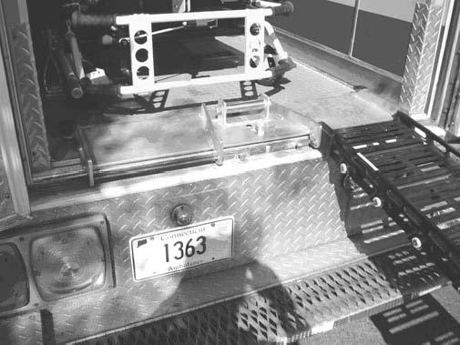
5 Transition Plate Description: As its name implies, the transition plate serves as a transition point between the ramps and the ambulance floor. Made from aluminum, the transition plate is light in weight and easily removable. When in use, it lies flat on the floor near the rear entrance to the ambulance s action area. There it is secured with three ² -13 hand-tight fasteners into threaded floor plates. The ramps are hooked over rods located to the outermost ends of the transition plate. A roller designed to prevent hard bends in the winch s wire rope during operation is attached to the center of the transition plate. The transition plate s inside leading edge is beveled to allow for a smooth landing between the ambulance floor and ramps. The transition plates must be removed when not in use. Otherwise, the rear doors won t close properly. Page 5 of 23

6 Transition Plate Installation: First, don a pair of leather gloves. Then, remove the transition plate from the rear outside cabinet. Lay the transition plate over the safety hook and flat onto the floor. Then, align the three pre-drilled holes with the threaded floor plates located beneath the transition plate. Slide each fastener into the pre-drilled holes and through the transition plate. Turn the fasteners clockwise into the threaded floor plates, by hand until snug. Don t use tools to tighten them. Keep the threaded floor plates free from dirt to allow for maximum penetration. Lubricate as needed for smooth operation. Before each winch operation, check to ensure the hand-tight screws haven t loosened up from vibration. To remove the transition plate, turn the hand-tight fasteners in a counter-clockwise direction to unscrew from the floor plates. Always, stow the fasteners in the designated stowage rack so that they are not misplaced. Figure 3 -Transition plate before installation. Page 6 of 23


7 Figure 4 -Transition plate is notched out to fit over safety hook. Roller & center hand-tight fastener are also visible. Figure 5 -Hand-tight fasteners used to install transition plate. Page 7 of 23

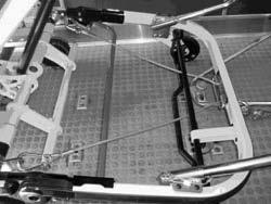
8 Ramps: Figure 6 -Transition plate after installation (view from within ambulance) The Bariatric unit includes two ramps that are 11 ² feet long and 1 foot wide. The ½inch sides prevent the stretcher breakaway head assembly wheels and casters from rolling off the edge. Both ramps are hinged to fold in thirds ( or in two 6ft lengths ) for storage within side compartments. The foot of each ramp is also hinged and has a beveled landing where it comes in contact with the ground. The upper ends are slotted underneath, across their width. This allows for hooking ramps onto the transition plate s horizontal rods. Page 8 of 23

9 Setting-up the ramps: The hinges are pinch points. As pinch points pose a hazard, they are painted red or yellow. The ramps are stored in the outside main O2 cabinet. Their tight fit limits movement while traveling, but also makes it difficult to store and remove them. Wear leather gloves while handling ramps to preclude knuckle busting. Also, make sure the pinch points are clear of all body parts when carrying, handling, unfolding or folding during set-up, break down and storage. Lay a folded ramp down, with the notched end on the bottom section closest to the ambulance. For now, the notch should be facing upward. (The inside of the fold is the bottom of the ramp) Unfold the ramp by lifting it upward until fully extended as shown in figure 8. The ramp is now upside down. Roll the ramp over so that the notched hook is underneath as shown in figure 9. Pick the ramp up from the notched end and hook it over the transition plate rod as shown in figure 10. Grab the ramp from above the hinged foot-end and pull it to ensure it is fully extended and stable. Repeat this process for the second ramp. Page 9 of 23

10 Figure 7 -Ramp folded in half while lying on side. Tri-fold configuration also available. Page 10 of 23


11 Figure 8 -With hook end closest to ambulance, unfold ramp without hands being near center pinch point. Then extend landing end of ramp. Figure 9 -Roll ramps over while keeping your hands free of pinch points. Page 11 of 23

12 Page 12 of 23
13 Ramp Angles: TRANSAFE BARIATRIC The ramps can be used to bridge across landings that are as high as the ambulance floor off the ground. Avoid bridging down into the ambulance from a higher surface or up from the ambulance to a higher surface. The ramps have two angles that you must manage, lengthwise and sideward. The only thing holding the stretcher down on the ramps is gravity. When the center of gravity shifts, the stretcher is no longer stable and will tip. If ramp angles aren t parallel lengthwise and level across the width, the stretcher will tilt and the center of gravity will shift. Hence, the stretcher will tip over and off the ramps, causing serious injury. Lengthwise the angle of the ramps should be near parallel to accommodate four-point contact with the stretcher. The ramps are designed to rise up and down independently which allows for using them where minor surface differences exist. However, a stretcher s free-floating wheel can drift over the ramp s ½-inch edge, placing the stretcher in peril of tipping. Remember, four of the stretcher wheels and casters should remain in contact with the ramps at all times. Both ramps must be level across their width. Neither ramp should lean inward or outward; from side-to-side or to one side. Additionally, the ramps shouldn t rock from side to side. Instability from side to side will cause the center of gravity to shift. Never risk your patient s safety by using ramps that aren t stable. If you can t stabilize the ramps, don t move the patient across them. Reposition the ambulance if the foot-end doesn t have solid contact with the ground. For instance, if the foot-end rests on the edge of a curb and you foresee that the ramp would drop under the weight of a patient, then the ramps must be reconfigured to prevent movement. Never move the ambulance with ramps attached. Doing so will cause irreparable damage to the ramps, transition plate, hand-tight fasteners and threaded floor-plates. Moving the stretcher to and from ambulance: When patient loaded, never roll the bariatric transport cot in a raised position. Lower it to the lowest position as soon as possible after loading, but before moving. Moving obese patients in a raised position places the stretcher at risk of tipping over. Page 13 of 23

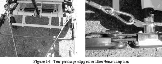
14 Inspecting the stretcher tow package, before winching: Stryker Bariatric Cots only. The STRYKER bariatric transport stretcher is equipped with a tow package to load and unload patients weighing up to 1,600 pounds. By design, the tow package can be removed when not in use. However, you should leave it attached so that it is not misplaced. Since the installation isn t permanent, you must inspect it before each shift. The visual inspection can be performed by looking up from under the breakaway head assembly or looking beneath the head-end storage pouch. See figure Make sure the stretcher s tow package is hooked to the litter base adapters on both sides. The adapters are attached to the outer rail near the breakaway head section s pivot points. See figure Make sure the tow package cables are positioned above the red bar and safety bar and below the black bar. See figure 15 3 Make sure the tow ring runs through the tow harness loop bracket. The bracket is attached to the center of the breakaway head assembly s outer rail. Later, the tow ring will be used to connect the winch cable by a single clip. See figure 16. Page 14 of 23

15 Page 15 of 23


16 Setting up the winch: The winch is mounted inside a box to guard against injury. The box is held down to the threaded floor plates using two ² œ13 hand tight screws. Prior to each use, turn the hand tight screws clockwise to ensure they are tight and haven t loosened up from vibration. Don t use tools to tighten them. See figure 17. Plug in winch power as seen in figure 18. Page 16 of 23
. This position provides the best view of the cable in operation.")

17 Winch operator: The winch must be operated through the side entrance during loading and unloading operations. See figure 19. (Important! TWO OR MORE TRAINED PERSONNEL MUST REMAIN WITH THE PATIENT LOADED COT IN ORDER TO GUIDE THE COT UP OR DOWN THE S ). This position provides the best view of the cable in operation. Extend the remote control cable between the cab and the winch, and out the side door. Make sure that both the winch power and remote control cables don t come in contact with sharp edges or lie in the path of moving objects, such as the wire rope. As the operator it is your responsibility to watch the cables path during operation and listen to those who are guiding the stretcher. No one is authorized to occupy the action area, between the stretcher and the winch, while winching the stretcher up or down the ramps. Page 17 of 23

18 Attaching wire rope to stretcher before loading: A snap-hook is attached to the bitter-end of the wire rope. While wearing leather gloves, free-spool the wire rope until the hook reaches the end of the ramps. Run the wire rope under the antlers. See figure 20. Make sure the wire rope runs across the roller at the Transition plate and not to the side of the roller. See figure 21. Align the stretcher s breakaway head assembly wheels with each ramp landing. This is the ready position. While other person(s) hold the foot end of the stretcher stable, clip the hook down onto the stretcher s tow ring. Don t use the stretcher s wheel locks to hold the stretcher in the ready position, while occupied by a patient. Before winching, visually inspect the entire wire rope s length between the winch and the stretcher for fraying. If fraying is observed or you suspect the wire rope is unsafe, don t use the winch until a qualified mechanical technician inspects the equipment. The the wire rope and winch should be inspected at the end of each day, whenever the Baraitric Unit is available for use. Page 18 of 23


19 Loading the stretcher: Begin winching by moving the toggle switch forward. Guide the stretcher to the right side as it moves up the ramps so that the stretcher s breakaway head assembly doesn t get hung up on the cot fastener lock rail (AKA lock down bar) See figure 22. A center mounted cot fastener set up is the preferred configuration. However, certain state regulations may preclude using the recommended center mounted fasteners systems as the Bariatric stretcher s width doesn t allow for aisle-space that complies with some regulations. As a result, the antlers and lock-bar are side Page 19 of 23

20 mounted. The off-center mounting creates an operational conflict with the ramps, transition plate roller and the winch s wire rope that are centered on the ambulance. The offset poses a risk of fouling the hook and the antlers. To avoid risk, the winch operator ensures the stretcher s breakaway head assembly wheels never cross the yellow line painted across the action area floor. Doing so prevents contact between the antlers and the hook. See figure 23. Failure to prevent contact between the hook and antlers while the wire rope is under tension will cause damage and personal injury. Unfortunately, being told that the head assembly wheels must not cross the yellow line is not the same as being told how to accomplish this. To prevent the breakaway head section wheels from crossing the yellow line, avoid continuous towing. As the front of the stretcher is half way into the ambulance begin toggling the remote control switch, forward and off. Repeat this step until the stretcher is in position. Doing so allows you to inch the stretcher forward. This is a critical aspect of the operation. Don t be hasty. Take your time. Once the head assembly load wheels reach the yellow line, release the toggle switch. ONLY when all four of the cot swivel casters are inside the ambulance, disconnect the hook from the tow ring until you are ready to lower the stretcher again. Manually roll the stretcher into the antlers and hook the stretcher into the lock-bar. While loading is complete, your work is not. The wire rope and hook pose a tripping hazard and must be moved out of the way. Don t winch the wire rope and hook in tight. Page 20 of 23

21 Instead, hook the wire rope to the winch cover s driver s side handle and winch in until the wire rope no longer presents a tripping hazard. Unloading the stretcher: Before unloading the stretcher, install the push/pull handles if the cot is so equipped. Then disengage the lock-bar and manually roll the stretcher back so that the head assembly wheels are behind the yellow line. Disconnect the hook from the winch cover and slacken the wire rope. Once again, make sure the wire rope runs under the antlers. Connect the hook to the stretcher s tow ring. Reel out enough wire rope so that the stretcher s foot-end can be pushed or pulled out onto the ramps. Once the weight of the stretcher pulls the wire rope taught, use the remote control to lower the stretcher. While the stretcher descends the ramps it must be guided so the wire rope lands on the transition plate roller. If the wire rope lands off to the side of the roller, you must stop unloading and reload to a point where the stretcher can be guided so that the wire rope lands on the roller. Never try to manhandle the cable onto the rollers. Allow the machinery to do the work. Once the stretcher s breakaway section load wheels roll off the ramps, hold the stretcher steady while the hook is released. Storage: The Bariatric Unit has outside cabinets used to store ramps, push/pull handles, transition-plate and hand tight fasteners. This equipment must be properly stored whenever the vehicle is moving, as illustrated in figures 25 and 26. Additionally, the Page 21 of 23

22 winch cover must be secured with a bungee cord to prevent it from becoming a missile hazard. See figure 27. Page 22 of 23

23 Page 23 of 23
Assembly & Operator s Manual
 Assembly & Operator s Manual LiftGator XTR 1200lbs Removable Liftgate TM Visit our website at: www.liftgator.com WARNING: Read the entirety of this manual before using the LiftGator. Failure to do so can
RAMPAGE POWER LIFT RAMP
 RAMPAGE POWER LIFT RAMP INSTALLATION AND OPERATING INSTRUCTIONS (3/10/07) The Rampage Power Lift Ramp is the fast, easy, and safe way to load a motorcycle into a truck. One person can load or unload a
Fast Master Products, Inc. P.O. Box 654, Katy Texas Tel: (281) Fax: (281)
 Fax: (281)") Fast Master Products, Inc. P.O. Box 654, Katy Texas 77492-0654 Tel: (281) 391-6750 Fax: (281) 391-6760 Email: info@cruiserlift.com Easy installation and removal from the pick-up bed. Compatible with all
Fast Master Products, Inc. P.O. Box 654, Katy Texas 77492-0654 Tel: (281) 391-6750 Fax: (281) 391-6760 Email: info@cruiserlift.com Easy installation and removal from the pick-up bed. Compatible with all
SIDE PULL WINCHING WITH THE 35K WINCH TWO PART LINE WARNING
 0011.4 00 90 SIDE PULL WINCHING WITH THE 35K WINCH TWO PART LINE WARNING Performing a 35K Winch 90 Degree Side-Pull with the FWTRD should be performed ONLY after determining that a straight line pull configuration
LOADING THE TDRT WARNING LOADING/UNLOADING OPERATION
 0012.3 00 LOADING THE TDRT WARNING LOADING/UNLOADING OPERATION All persons not involved in the loading or unloading operation must stand clear the full length of prime mover and Tilt Deck Recovery Trailer.
Instruction Manual 30K - Fifth Wheel Hitch Part Number 30054
 You can take it with you. ELKHART, IN., OAKVILLE, ONT. Instruction Manual 30K - Fifth Wheel Hitch Part Number 30054 DEALER/INSTALLER: (1) Provide this Manual to end user. (2) Physically demonstrate hitching
THE GLIDER 5th Wheel Attachment
 April 2007 APPLICATION: INSTALLATION INSTRUCTIONS MODEL NO. 70460 70046 THE GLIDER 5th Wheel Attachment For use on short bed pickup applications US Patent No. 6247720 COMPLETE PARTS LIST Part Description
OPERATOR S MANUAL 2200 SERIES LIFT - LIL HOISTER. July 2017
 July 2017 OPERATOR S MANUAL 2200 SERIES LIFT - LIL HOISTER! Before operating this lift, read and understand this Operator s Manual. Become familiar with the potential hazards of this unit. Call SUMNER
Operator s Manual. 2010, 2015, 2020, 2025 Material Lifts
 Operator s Manual 2010, 2015, 2020, 2025 Material Lifts April 2005! Before operating this lift, read and understand this Operator s Manual. Become familiar with the potential hazards of this unit. Call
INSTALLATION, OPERATION & MAINTENANCE INSTRUCTIONS
 June 2004 INSTALLATION, OPERATION & MAINTENANCE INSTRUCTIONS Please be sure that this document is given to the end user of this product. It contains many important items relating to the proper usage of
OPERATING & INSTRUCTION MANUAL
 251 Welsh Pool Rd Exton, PA 19341 610-941- 4333 www.safetyhoistcompany.com OPERATING & INSTRUCTION MANUAL VH-300 BRIGGS & STRATTON VH-300 HONDA IMPORTANT RETAIN THIS MANUAL For instruction on assembly
Peg-Harness installation instructions
 Peg-Harness installation instructions I know it s not the easiest thing to do, but PLEASE READ THESE INSTRUCTIONS COMPLETELY so you will understand what you are trying to accomplish before you start drilling
Installation Instructions
 Equipment Required: Wrenches: 9/16, 3/4, 1-1/8 Drill Bits: 11/32 Torque Wrench capable of reading 260 ft-lbs. Installation Instructions IN DEALERS: Please give these instructions to your customer. Do Not
INSTALLATION INSTRUCTIONS AND OWNER S MANUAL
 INSTALLATION INSTRUCTIONS AND OWNER S MANUAL Thank you for purchasing the AlloyCover from WeatherTech. Manufactured with pride using superior quality materials and workmanship. With proper care, your cover
INSTALLATION / OPERATING INSTRUCTIONS Reese Elite Series FIFTH WHEEL SLIDER HITCH
 INSTALLATION / OPERATING INSTRUCTIONS Reese Elite Series FIFTH WHEEL SLIDER HITCH DEALER/INSTALLER: (1) Provide this Manual to end user. (2) Physically demonstrate hitching and unhitching procedures in
Important. Contents. Contact us:
 Operator's Manual Third Edition Third Printing Important Read, understand and obey these safety rules and operating instructions before operating this machine. Only trained and authorized personnel shall
Important. Contents. Contact us:
 Operator's Manual First Edition Ninth Printing Important Read, understand and obey these safety rules and operating instructions before operating this machine. Only trained and authorized personnel shall
ALUMINUM CARGO CARRIER WITH FOLDING RAMP
 ALUMINUM CARGO CARRIER WITH FOLDING RAMP OWNER S MANUAL WARNING: Read carefully and understand all ASSEMBLY AND OPERATION INSTRUCTIONS before operating. Failure to follow the safety rules and other basic
INSTALLATION INSTRUCTIONS
 INSTALLATION INSTRUCTIONS Thank you for purchasing a LOMAX TM Hard Tri-Fold or Professional Series Cover. Agri-Cover, Inc. proudly manufactured this cover using superior quality materials and workmanship.
INSTRUCTION MANUAL TITAN 16K - Fifth Wheel Hitch Plymouth MI
 You can take it with you. INSTRUCTION MANUAL TITAN 16K - Fifth Wheel Hitch Plymouth MI Product No. 30866 DEALER/INSTALLER: END USER: (1) Provide this Manual to end user. (2) Physically demonstrate hitching
On-A-Roll Lifter Instruction Manual for Standard Models Read Before Use!
 On-A-Roll Lifter Instruction Manual for Standard Models Read Before Use! Important instructional, safety and precautionary information! It is the user s responsibility to exercise good judgment, common
INSTALLATION INSTRUCTIONS AND OWNER S MANUAL
 INSTALLATION INSTRUCTIONS AND OWNER S MANUAL Thank you for purchasing the AlloyCover from WeatherTech. Manufactured with pride using superior quality materials and workmanship. With proper care, your cover
All trailers will come pre assembled You will have the Naked frame (No accessories) attached. See drawing of trailer below.
 attached. See drawing of trailer below.") Operation Manual Version 9 Please make sure BEFORE you use the trailer you have read this entire booklet and have conducted the pre delivery check list found in the plastic pocket with this Operation Manual.
Operation Manual Version 9 Please make sure BEFORE you use the trailer you have read this entire booklet and have conducted the pre delivery check list found in the plastic pocket with this Operation Manual.
INSTRUCTION MANUAL 16K - Fifth Wheel Hitch
 You can take it with you. INSTRUCTION MANUAL 16K - Fifth Wheel Hitch Product No. 30047 DEALER/INSTALLER: END USER: (1) Provide this Manual to end user. (2) Physically demonstrate hitching and unhitching
B&W Trailer Hitches 1216 Hawaii Road / PO Box 186 Humboldt, KS P: F:
 B&W Trailer Hitches 1216 Hawaii Road / PO Box 186 Humboldt, KS 66748 P:620.473.3664 F:620.869.9031 NOTE: We recommend reading instructions before beginning the installation. Ford OEM Mount System Slider
PRODUCT DOCUMENTATION PARTS PORTAL
 M-16-25 JULY 2017 To find maintenance & parts information for your GPTLR Liftgate, go to www. maxonlift.com. Click the PRODUCTS, TUK-A-WAY & GPTLR buttons. Open the Maintenance Manual in the PRODUCT DOCUMENTATION
X.L. BAND W/ SPRING ASSIST INSTRUCTION MANUAL
 PARTS LIST X.L. BAND W/ SPRING ASSIST INSTRUCTION MANUAL (2) Bands (1) Handle assembly (2) Side hinge assemblies (1) Left rear hinge assembly (1) Right rear hinge assembly (2) front spring s (2) rear spring
OPERATOR S MANUAL R-Series Roust-a-Bout
 December 2017 OPERATOR S MANUAL R-Series Roust-a-Bout! Before operatingthis lift, readand understandthis Operator s Manual. Become familiar with the potentialhazards of thisunit. Call SUMNER if youhaveanyquestions.
M REV. D AUGUST 2010 OPERATION MANUAL GPT-25, GPT-3, GPT-4, GPT-5, & GPTWR-3
 M-08-34 REV. D AUGUST 2010 OPERATION MANUAL GPT-25, GPT-3, GPT-4, GPT-5, & GPTWR-3 MAXON Lift Corp. 2010 TABLE OF CONTENTS LIFTGATE TERMINOLOGY... 5 RECOMMENDED DAILY OPERATION CHECKS... 6 DECALS (GPT
INSTRUCTION MANUAL 16K - Fifth Wheel Hitch
 You can take it with you. INSTRUCTION MANUAL 16K - Fifth Wheel Hitch Product No. 30047 DEALER/INSTALLER: END USER: (1) Provide this Manual to end user. (2) Physically demonstrate hitching and unhitching
DWHOIST. Drywall Hoist Assembly & Operating Instructions
 DWHOIST Drywall Hoist Assembly & Operating Instructions READ ALL INSTRUCTIONS AND WARNINGS BEFORE USING THIS PRODUCT. SAVE THESE INSTRUCTIONS FOR FUTURE REFERENCE. This manual provides important information
M REV. J APRIL 2012 OPERATION MANUAL GPTLR-25, GPTLR-33, GPTLR-44 & GPTLR-55
 M-04-05 REV. J APRIL 2012 OPERATION MANUAL GPTLR-25, GPTLR-33, GPTLR-44 & GPTLR-55 MAXON Lift Corp. 2012 TABLE OF CONTENTS WARNINGS...4 LIFTGATE TERMINOLOGY...5 RECOMMENDED DAILY OPERATION CHECKS...6
Pontoon Assembly Instructions and manual. Read before using hoist.
 Page 1 Pontoon Assembly Instructions and manual. Read before using hoist. For Models 32BL18, 32BL22, 32BL25 and 42BL28 R Model 32BL22 Shown Proudly Made in Michigan By NuCraft Metal Products 402 Southline
M REV. E JUNE 2009 OPERATION MANUAL GPTLR-25, GPTLR-33, GPTLR-44 & GPTLR-55
 M-04-05 REV. E JUNE 2009 OPERATION MANUAL GPTLR-25, GPTLR-33, GPTLR-44 & GPTLR-55 MAXON Lift Corp. 2009 TABLE OF CONTENTS WARNINGS...4 LIFTGATE TERMINOLOGY...5 RECOMMENDED DAILY OPERATION CHECKS...6 DECALS...8
Instruction Manual 15K - Fifth Wheel Hitch Part Number 6030 & 6031
 DEALER/INSTALLER: (1) Provide this Manual to end user. (2) Physically demonstrate hitching and unhitching procedures in this Manual to end user. (3) Have end user demonstrate that he/she understands procedures.
Towing and Road Service Guide For Volkswagen Touareg. Quality and Education Services AAA Automotive 1000 AAA Drive Heathrow, FL 32746
 Towing and Road Service Guide For Volkswagen Touareg Quality and Education Services AAA Automotive 1000 AAA Drive Heathrow, FL 32746 June 15 th, 2003 Index Equipment availability 3 General Towing Information
OPERATION MANUAL RA-35 & RA-45
 M-13-02 REV. A NOVEMBER 2015 OPERATION MANUAL RA-35 & RA-45 To fi nd maintenance & parts information for your RA Liftgate, go to www.maxonlift.com. Click the PRODUCTS, SLIDELIFT & RA buttons. Open the
K Autoslide & K Autoslide
 HJ26077, Rev 16 07/18 5th wheel hitch 6077 18K Autoslide & 6107 21K Autoslide US Pat. 7,506,886 US Pat. 7,753,392 CA Pat. 2,576,427 AS Pat. 2007200421 Important Information WARRANTY POLICY, OPERATOR MANUALS
Single Seat Trailer. Owner s manual and safety instructions
 Single Seat Trailer Owner s manual and safety instructions Owner s Manual Every effort has been made to ensure your trailer is of top quality and proven safe design, ready to provide you with many years
<THESE INSTRUCTIONS MUST BE GIVEN TO THE END USER> B&W Trailer Hitches 1216 Hawaii Road / PO Box 186 Humboldt, KS P: F:
 B&W Trailer Hitches 26 Hawaii Road / PO Box 86 Humboldt, KS 6678 P:620.73.366 F:620.869.903 RAM OEM Mount System Installation Instructions 25,000 LBS.
B&W Trailer Hitches 1216 Hawaii Road / PO Box 186 Humboldt, KS P: F:
 B&W Trailer Hitches 1216 Hawaii Road / PO Box 186 Humboldt, KS 66748 P:620.473.3664 F:620.473.3766 NOTE: We recommend reading instructions before beginning the installation. GM OEM Mount System Slider
<THESE INSTRUCTIONS MUST BE GIVEN TO THE END USER> B&W Trailer Hitches 1216 Hawaii Road / PO Box 186 Humboldt, KS P: F:
 B&W Trailer Hitches 26 Hawaii Road / PO Box 86 Humboldt, KS 6678 P:620.73.366 F:620.869.903 Ford OEM Mount System Installation Instructions 20,000 LBS.
6/17 HJ26077 Rev 12. US Pat. 7,506,886 US Pat. 7,753,392 CA Pat. 2,576,427 AS Pat PAGE 1
 6/17 HJ26077 Rev 12 US Pat. 7,506,886 US Pat. 7,753,392 CA Pat. 2,576,427 AS Pat. 2007200421 PAGE 1 WARRANTY POLICY, OPERATOR MANUALS & REGISTRATION Go online to www.demco-products.com to review Demco
7/18 HJ26077 Rev 16. US Pat. 7,506,886 US Pat. 7,753,392 CA Pat. 2,576,427 AS Pat PAGE 1
 7/18 HJ26077 Rev 16 US Pat. 7,506,886 US Pat. 7,753,392 CA Pat. 2,576,427 AS Pat. 2007200421 PAGE 1 WARRANTY POLICY, OPERATOR MANUALS & REGISTRATION Go online to www.demco-products.com to review Demco
AL625 & AL625HD INSTALLATION & OWNER S MANUAL
 AL625 & AL625HD INSTALLATION & OWNER S MANUAL These instructions are provided to assist you in the installation of the AL625. If you require further assistance, our trained staff is ready to provide you
INSTRUCTION MANUAL 22K - Fifth Wheel Hitch
 You can take it with you. INSTRUCTION MANUAL 22K - Fifth Wheel Hitch Product No. 30033 DEALER/INSTALLER: (1) Provide this Manual to end user. (2) Physically demonstrate hitching and unhitching procedures
Important. Contents. Contact us:
 Operator's Manual Second Edition First Printing Important Read, understand and obey these safety rules and operating instructions before operating this machine. Only trained and authorized personnel shall
WHEELED LITTER CARRIER: EL3000
 WHEELED LITTER CARRIER: EL3000 INSTRUCTION MANUAL NSN 6530-01-591-9636 FareTec Inc. CAGE Code: 0R123 www.faretec.com & ECAT Training Video Available online Dimensions: Closed: 20 x 23 x 33 in. Boxed: 36
Installation Manual for Philips Intellivue MP5/20/30 VHM-25 Channel Mount Kit
 3875 Cypress Drive Petaluma, CA 94954 800.228.2555 707.773.1100 Fax 707.773.1180 www.gcx.com Installation Manual for Philips Intellivue MP5/20/30 VHM-25 Channel Mount Kit Install Time: 10-15 minutes The
<THESE INSTRUCTIONS MUST BE GIVEN TO THE END USER> B&W
 B&W Trailer Hitches 26 Hawaii Road / PO Box 86 Humboldt, KS 6678 P:620.73.366 F:620.869.903 GM Puck Mount System Installation Instructions 20,000 LBS.
DC Series Installation Manual (# )
") DC Series Installation Manual (# 101630) Page 1 of 33 In this booklet you will find: TOWER INSTALLATION... 3 U-Bolt Style mount... 4 Side Frame Style mount... 4 PIVOT INSTALLATION... 5 External Pivot Installation:
DC Series Installation Manual (# 101630) Page 1 of 33 In this booklet you will find: TOWER INSTALLATION... 3 U-Bolt Style mount... 4 Side Frame Style mount... 4 PIVOT INSTALLATION... 5 External Pivot Installation:
Owner s Manual Read and keep this manual. Patents World Wide
 Owner s Manual Read and keep this manual. Patents World Wide S & S Industries, Inc., Sarasota, FL, USA www.trail-gator.com Copyright 2006 All Rights Reserved The following manual is provided to assist
MODEL XLT-X2 BIKE TRAILER. Owner s Manual should be kept for future reference
 1 MODEL XLT-X2 BIKE TRAILER Owner s Manual should be kept for future reference 1. Completely read and understand Owner s Manual before assembling or operating this product. 2. This product should be assembled
OWNER S MANUAL. Sentry & Sentry CT THREE YEAR WARRANTY. Phone: ( ) Fax: (605) SAFETY INSTRUCTIONS
 Fax: (605) SAFETY INSTRUCTIONS") OWNER S MANUAL Sentry & Sentry CT HARD ROLL-UP TRUCK BED COVER SAFETY INSTRUCTIONS 1. Do not place objects on or against cover or framework. 2. Do not tie cargo to truck bed cover framework. 3. Never allow
OWNER S MANUAL Sentry & Sentry CT HARD ROLL-UP TRUCK BED COVER SAFETY INSTRUCTIONS 1. Do not place objects on or against cover or framework. 2. Do not tie cargo to truck bed cover framework. 3. Never allow
M REV. C MARCH 2011 OPERATION MANUAL GPSLR-33 & GPSLR-44
 M-08-13 REV. C MARCH 2011 OPERATION MANUAL GPSLR-33 & GPSLR-44 MAXON Lift Corp. 2011 TABLE OF CONTENTS WARNINGS... 4 LIFTGATE TERMINOLOGY... 5 RECOMMENDED DAILY OPERATION CHECKS... 6 DECALS (WITH SMART
Spraying boom INDEX. Booklet. user manual TECHNICAL INFORMATION...2 INFORMATION ABOUT ADJUSTMENTS... 20
 Booklet 9 Spraying boom INDEX Serial number Edition 1 05-2008 tittle pag tittle pag TECHNICAL INFORMATION...2 equipment general description...2 technical specifications...2 technical specification diagram...2
Model E600 Tarping System
 10 Boulder Parkway N. Oxford, MA 01537 866-353-5826 pioneersales@wastequip.com www.pioneercoverall.com Model E600 Tarping System Installation Instructions WARNING: In order to prevent damage, the tarp
Model 3770 WARNING. Failure to comply with the safety information in these instructions could result in serious injury or death.
 B&W Trailer Hitches 1216 Hawaii Road / PO Box 186 Humboldt, KS 66748 P:620.473.3664 See Limited Lifetime Warranty at F:620.869.9031 bwtrailerhitches.com/warranty NOTE: We recommend reading instructions
PAGE 1. 7/18 HJ26141 Rev 12
 PAGE 1 7/18 HJ26141 Rev 12 WARRANTY POLICY, OPERATOR MANUALS & REGISTRATION Go online to www.demco-products.com to review Demco warranty policies, operator manuals and register your Demco product. Please
S-SERIES AND K-SERIES SERVICE MANUAL
 -PRINT- S-SERIES AND K-SERIES - TABLE OF CONTENTS- MAY 2014 INSTALLATION II. INSTALLATION T his chapter contains instructions for installing the RICON S-Series and K-Series Public Use wheelchair lift into
Model 521 Universal Oxygen Cylinder Bracket
 Model 521 Universal Oxygen Cylinder Bracket and Users' Manual Notice to Installer This manual contains instructions for installing, using, and maintaining the Model 521 Universal Oxygen Cylinder Bracket.
How to fold your MGB top (pre 1970 pack away top & frame)
") How to fold your MGB top (pre 1970 pack away top & frame) It is most important that the instructions given for raising, lowering and folding the hood are followed. Do not use undue force on the hood frame-members.
How to fold your MGB top (pre 1970 pack away top & frame) It is most important that the instructions given for raising, lowering and folding the hood are followed. Do not use undue force on the hood frame-members.
5-13 HJ26002 rev 1. US Pat. 7,506,886 US Pat. 7,753,392 Patent Pend. CA Patent Pend. AS
 5-3 HJ26002 rev US Pat. 7,506,886 US Pat. 7,753,392 Patent Pend. CA Patent Pend. AS VERY IMPORTANT PLEASE READ CAREFULLY The Hijacker AutoSlide fifth wheel hitch was designed for use with recreational
Model 289F. Operator s Manual for Morse Model 289F. MORStak TM Forklift-Mounted Drum Racker. The Specialist In Drum Handling Equipment
 Contents Page Receiving Procedures.................... 1 Warranty............................. 1 Safety Information..................... 1-2 Machine Description................... 3 Operating Instructions....................
INSTRUCTION MANUAL R16 - Fifth Wheel Hitch
 You can take it with you. INSTRUCTION MANUAL R16 - Fifth Wheel Hitch Product No. 30866 DEALER/INSTALLER: END USER: (1) Provide this Manual to end user. (2) Physically demonstrate hitching and unhitching
BROOKS STAIRLIFTS SUPERGLIDE 120
 BROOKS STAIRLIFTS SUPERGLIDE 120 INSTALLATION PROCEDURES CONTENTS Health And Safety Hazards 3 Unpacking the Stairlift Carriage 4 Pre-Installation Procedure 5 Box Contents 6 Installation Tools 9 1.1 Required
SERIES A & AA ROLLER DOORS INSTALLATION GUIDE
 SERIES A & AA ROLLER DOORS INSTALLATION GUIDE THESE INSTRUCTIONS ARE PROVIDED FOR USE BY EXPERIENCED INSTALLERS OF GARAGE DOORS BY UNDER-TAKING THE INSTALLATION OF THIS DOOR, THE INSTALLER UNDERSTANDS
MAINTENANCE INSTRUCTIONS
 MAINTENANCE INSTRUCTIONS LSR90 SERIES RAMPS Link Mfg. Ltd. 223 15th St. N.E. Sioux Center, IA USA 51250-2120 The LSR 90 fits Mercedes Benz Sprinters, Ford Transits mid and high roof, Nissan NV high roof,
 Manufacturers of Patented Truck Trailering Lifts 16 W. West Hill Road Barkhamsted, CT 06063. Ph. 860-379-7772 or 1-800-450-8659 Fax 860-738-2777 WWW.TRUHITCH.COM INFO@TRUHITCH.COM 1 Read All Instructions
Pegasus / Pegasus MK2 Trolley. User Manual
 Pegasus / Pegasus MK2 Trolley User Manual IMPORTANT NOTE To comply with BS EN 1789: 2007, the four-point harness MUST be used as a patient restraint and the Pegasus MUST be secured with the two-part locking
<THESE INSTRUCTIONS MUST BE GIVEN TO THE END USER> B&W Trailer Hitches 1216 Hawaii Road / PO Box 186 Humboldt, KS P: F:
 B&W Trailer Hitches 26 Hawaii Road / PO Box 86 Humboldt, KS 66748 P:620.473.3664 F:620.869.903 Ford OEM Mount System Installation Instructions 20,000
KWSL2000RM ! CAUTION!! READ AND UNDERSTAND THIS MANUAL BEFORE INSTALLATION AND OPERATION OF THIS PRODUCT. DO NOT RETURN THIS PRODUCT TO SELLER.
 Assembly & Operating Instructions KWSL2000RM 2000 Lb. 12VDC Electric Winch! CAUTION!! READ AND UNDERSTAND THIS MANUAL BEFORE INSTALLATION AND OPERATION OF THIS PRODUCT. DO NOT RETURN THIS PRODUCT TO SELLER.
TABLE OF CONTENTS Safe Use Checklist Registration & Recal Assistance Warnings Base Features Carrier Features Securing Child In Carrier
 TABLE OF CONTENTS Safe Use Checklist...4 Registration & Recall...5 Assistance...5 Warnings...6 Base Features Base Overview... Storage Compartment...3 Recline Adjustment...3 LATCH Removal & Storage...4
OWNER S MANUAL. Sentry & Sentry CT THREE YEAR WARRANTY. Phone: ( ) Fax: (605) SAFETY INSTRUCTIONS
 Fax: (605) SAFETY INSTRUCTIONS") OWNER S MANUAL Sentry & Sentry CT HARD ROLL-UP TRUCK BED COVER SAFETY INSTRUCTIONS 1. Do not place objects on or against cover or framework. 2. Do not tie cargo to truck bed cover framework. 3. Never allow
OWNER S MANUAL Sentry & Sentry CT HARD ROLL-UP TRUCK BED COVER SAFETY INSTRUCTIONS 1. Do not place objects on or against cover or framework. 2. Do not tie cargo to truck bed cover framework. 3. Never allow
Name: ACORN Inc. Address: 6450 Kingspointe Parkway, Unit 1, Orlando, Florida, IMPORTANT!
 MANUFACTURER INFORMATION: Name: ACORN Inc. Address: 6450 Kingspointe Parkway, Unit 1, Orlando, Florida, 32819 Helpline: 407 650-0216 IMPORTANT! READ THESE PROCEDURES THOROUGHLY PRIOR TO stair lift INSTALLATION
B&W Trailer Hitches 1216 Hawaii Road / PO Box 186 Humboldt, KS P: F: " Split Lock Washers 8
 B&W Trailer Hitches 1216 Hawaii Road / PO Box 186 Humboldt, KS 66748 P:620.473.3664 F:620.869.9031 NOTE: We recommend reading instructions before beginning the installation. Companion Slider Hitch Installation
OPERATOR S MANUAL EL EQUIPMENT LIFT. US 7514 Alabonson Road Houston, TX phone: fax:
 OPERATOR S MANUAL EL - 405 EQUIPMENT LIFT February 22, 2008! Before operating this lift, read and understand this Operator s Manual. Become familiar with the potential hazards of this unit. Call SUMNER
CAUTION -TABLE OF CONTENTS- II. OPERATING INSTRUCTIONS
 -PRINT- -TABLE OF CONTENTS- II. OPERATING INSTRUCTIONS his chapter contains safety precautions, daily safety check instructions, control and indicator descriptions, and operating instructions that apply
ASSEMBLY INSTRUCTIONS & OWNER S MANUAL
 Caution: For Safety Read and Follow Assembly and Operating Instructions Carefully ASSEMBLY INSTRUCTIONS & OWNER S MANUAL McCONKEY INC. P.O. Box 1362 Seeley Lake, MT 59868 1 of 7 NEED HELP? Please visit
MAINTENANCE WEIGHT RATINGS WARNINGS. warning: never exceed your vehicle manufacturer's recommended towing capacity
 Installation instructions warning: never exceed your vehicle manufacturer's recommended towing capacity Round Bar WEIGHT DISTRIBUTION kit MAINTENANCE Keep the socket-mounted ends of the spring bars and
Model 3400 ATTENTION: WARNING
 B&W Trailer Hitches 1216 Hawaii Road / PO Box 186 Humboldt, KS 66748 P:620.473.3664 F:620.473.3766 NOTE: We recommend reading instructions before beginning the installation. Companion Slider Hitch Installation
EZ Hauler 2500 Training & Procedure Manual
 EZ Hauler 2500 Training & Procedure Manual Load Capacity One of the most important considerations when operating this machine is the Load Capacity of the EZ Hauler 2500 s boom. The maximum weight capacity
3/14 HJ26077 Rev 1. US Pat. 7,506,886 US Pat. 7,753,392 CA Pat. 2,576,427 AS Pat
 3/14 HJ26077 Rev 1 US Pat. 7,506,886 US Pat. 7,753,392 CA Pat. 2,576,427 AS Pat. 2007200421 VERY IMPORTANT PLEASE READ CAREFULLY The Hijacker Autoslide fifth wheel hitch was designed for use with recreational
VHM-P (Non-Locking) and VHM-PL (Locking) Variable Height Arm with Slide-In Mounting Plate
 and VHM-PL (Locking) Variable Height Arm with Slide-In Mounting Plate") 3875 Cypress Drive Petaluma, CA 94954 800.228.2555 +1.707.773.1100 Fax 707.773.1180 www.gcx.com VHM-P (Non-Locking) and VHM-PL (Locking) Variable Height Arm with Slide-In Mounting Plate (Refer to qualified
3875 Cypress Drive Petaluma, CA 94954 800.228.2555 +1.707.773.1100 Fax 707.773.1180 www.gcx.com VHM-P (Non-Locking) and VHM-PL (Locking) Variable Height Arm with Slide-In Mounting Plate (Refer to qualified
SCAMP AND UTILITY MODELS SELF-PROPELLED BELT DRIVE SERVICING 4502, 4503, 8602, 8603 WITH F SERIES ENGINES
 4502, 4503, 8602, 8603 WITH F SERIES ENGINES Adjustments and servicing of the Scamp and Utility self-propelled mowers are very different from all previous models of self-propelled mowers. BEFORE ANY ADJUSTMENTS
ESCONDIDO FIRE DEPT TRAINING MANUAL Section Truck Module Page 1 of 7 Ladder Introduction Revised
 Truck Module Page 1 of 7 LADDER INTRODUCTION Introduction The three major objectives of fire ground operations are Rescue, Fire Control, and Property Conservation. In order to obtain these objectives,
Q5 5 th Wheel. Unpacking Assembly / Installation
 PA1 Unpacking Assembly / Installation Installer: Read and understand this manual. Fully instruct and demonstrate the operation of this 5 th Wheel Hitch to the End-User. Include the importance of observing
Patriot. Aluminum and Steel 5spring. Step #1 Tarp Spool with Gear Motor (Includes Instructions for Optional Wind Deflector)
") Aluminum and Steel 5spring Qty. Component Parts Description: LONG BOX: (1) 103 Aluminum Tarp Axle (2) 98 Upper Arms with 90 Degree Elbow (2) Lower Aluminum ( 84 ) (1) Aluminum Cross Tube SMALL HARDWARE
Aluminum and Steel 5spring Qty. Component Parts Description: LONG BOX: (1) 103 Aluminum Tarp Axle (2) 98 Upper Arms with 90 Degree Elbow (2) Lower Aluminum ( 84 ) (1) Aluminum Cross Tube SMALL HARDWARE
Amtryke Model AM-12 & AM-16
 Amtryke Model AM-12 & AM-16 Carton Contents Carefully remove and lay out all parts from the carton so as not to scratch or lose any parts or pieces. The shipping carton should contain the pictured items
** DO NOT EXCEED THE RECOMMENDED VEHICLE TOWING WEIGHT RATING ** DODGE RAM 1500
 10/3/2017 DODGE RAM 1500 WARNING!! BRAKE, FUEL, AND ELECTRICAL LINES MAY NEED TO BE LOOSENED OR REPOSITIONED TO PROVIDE CLEARANCE FOR NEW HARDWARE. ON SHORT BED MODELS, CHECK FOR ADEQUATE TURNING CLEARANCE
INSTALLATION INSTRUCTIONS
 INSTALLATION INSTRUCTIONS WARNING: NEVER EXCEED YOUR VEHICLE MANUFACTURER'S RECOMMENDED TOWING CAPACITY PIN-STYLE TRUNNION BAR WEIGHT DISTRIBUTION KIT MAINTENANCE Keep the socket-mounted ends of the spring
CALIFORNIA TRIMMER MOWER MAINTENANCE MANUAL
 CALIFORNIA TRIMMER MOWER MAINTENANCE MANUAL 2 Table of Contents Section 1: General Information Page Handle Assembly Instructions 4 Maintenance All Models 6 Oil Change Procedures All Models 9 Height Adjustment
R20 - Fifth Wheel Hitch
 You can take it with you. INSTRUCTION MANUAL R20 - Fifth Wheel Hitch Plymouth MI Product No. 30867 DEALER/INSTALLER: END USER: (1) Provide this Manual to end user. (2) Physically demonstrate hitching and
3875 Cypress Drive Petaluma, CA Fax
 3875 Cypress Drive Petaluma, CA 94954 800.228.2555 +1.707.773.1100 Fax 707.773.1180 www.gcx.com VHM-P (Non-Locking) Variable Height Arm with Fixed Angle Front End for Flat Panel / Keyboard Bracket (L Brackets
Remove the 3-11mm nuts holding mirror on. Don t drop the nuts!
 2005-2012 Ford Mustang Puddle Lamp Kit Parts List: Quantity: Tool List: LED Lamps 2 Flat head screwdriver Seals 2 Ratchet & Socket set OR Nuts 2 Adjustable Wrench Wiring harness 1 Drill & 11/16 th bit
Installation Instructions
 PIN BOX SHOWN ASSEMBLED Equipment Required: Fastener Kit: ST100F Wrenches: 15/16, 1 1/8 Drill Bits: Not Required White Lithium Grease, Torque Wrench Installation Instructions DEALER/INSTALLER: (1) Provide
Installation Manual for VHM-25 Series Arms Channel Mount
 3875 Cypress Drive Petaluma, CA 94954 800.228.2555 707.773.1100 Fax 707.773.1180 www.gcx.com Installation Manual for VHM25 Series Arms Channel Mount Install Time: 1015 minutes The purpose of this manual
Coupling & Uncoupling a Tractor-Trailer
 TRAINING TOOL Coupling & Uncoupling a Tractor-Trailer DRIVING THE FUTURE 2 Coupling and Uncoupling a Tractor-Trailer TRAINING TOOL Coupling a Tractor-Trailer 1 When operating articulating vehicles such
12V ELECTRIC WINCH 9000-LB. CAPACITY OWNER S MANUAL
 12V ELECTRIC WINCH 9000-LB. CAPACITY OWNER S MANUAL WARNING: Read carefully and understand all INSTRUCTIONS before operating. Failure to follow the safety rules and other basic safety precautions may result
Owner s Manual. Transport / Companion Wheelchairs M4TV M2TF M2TC M2TL HEALTH PRODUCTS, INC.
 Owner s Manual M4TV M2TF Transport / Companion Wheelchairs M2TL M2TC HEALTH PRODUCTS, INC. INTRODUCTION Congratulations on the purchase of your new companion chair. Please read this introduction with your