OWNER S MANUAL PERSONAL WATERCRAFT BOAT
|
|
|
- Eustacia Long
- 5 years ago
- Views:
Transcription


1 Enclosed are the operating instructions and warranty information for your new Karavan Trailer. Please review carefully before operating. BOAT OWNER S MANUAL PERSONAL WATERCRAFT UTILITY Product and specifications subject to change without notice. PONTOON
2 Karavan Trailers, Inc. Limited Warranty Policy Please register your trailer online at A complete Owner s Manual is available online Contact us at: warranty@karavantrailers.com or Karavan Trailers, Inc. warrants each new Karavan Trailers trailer to be free from defects in materials and workmanship for a period of one (1) year from the date of purchase. Karavan Trailers shall repair or replace, without charge, any parts found to be defective because of imperfect workmanship or materials, within a reasonable time after the trailer is returned at purchaser's expense to any Karavan Trailers authorized distributor or dealer. Who is covered? This warranty is extended to the original purchaser only. How do I make a claim? 1. Your claim must be filed on the Karavan website at: or in writing to: Karavan Trailers, Inc., 100 Karavan Drive, Fox Lake, WI, Claim must provide true and complete information when filed. 3. You must cooperate with Karavan when attempting to resolve the claim. 4. Only Karavan and authorized dealers may be used to fulfill the warranty claim. 5. Karavan may elect to repair or replace your product, or in some cases, offer you a refund. 6. Karavan will inform you whether your claim is covered by warranty within thirty days of receiving the trailer. 7. Any disputes must be resolved in state or federal court. What is not covered? Although you may use the parts and maintenance, and repair services of your choosing, we recommend using authorized dealers and parts for any repairs or maintenance, because improper or incorrect use of parts, maintenance, or repairs will void this warranty. Authorized parts are recommended for replacement of winches, lights, couplers, brakes, tongue jacks, and springs. Authorized dealers are listed on the Karavan website. The warranty will not cover defects or damage caused by unauthorized modifications or alterations. The warranty does not apply to any defect or malfunction caused by damage, unreasonable use, or failure to provide reasonable and necessary maintenance. The warranty will not cover damage caused by overloading the trailer beyond stated capacities or the use of improperly installed weight distribution hitches in conjunction with hydraulic surge brakes. Rust formation is not covered because the trailer is exposed to highly corrosive conditions. Tires are not covered. Warranty on tires shall be made through the nearest tire representative. Bearing cups, bearings and seals are covered for 180 days from date of purchase. The use of any unit as part of a rental fleet or use for commercial purposes voids this warranty. Other Limitations Any implied warranties, obligations, or liabilities including, but not limited to, any implied warranty of merchantability or implied warranty of fitness for a particular purpose, shall be limited in duration to the one-year duration of the written limited warranty. Karavan Trailers, Inc. shall not be liable for incidental expenses of the consumer including, without limitation: loss of time, inconvenience, towing charges, travel expenses, lodging, telephone, gas, or loss or damage to personal property or loss of wages.
3 Karavan Trailers, Inc. shall not be liable for any incidental or consequential damages for breach of this or any other warranty expressed or implied. This warranty gives you specific legal rights, and you may also have other rights which vary from State to State. Some States do not allow limitations on how long an implied warranty lasts, and/or the exclusion or limitation of incidental or consequential damages, so the above limitation or exclusion may not apply to you. Karavan Trailers, Inc. will follow any controlling warranty laws for trailers purchased in countries outside the United States. Bow Eye Safety Chain WARNING: Failure to tie down the bow independently from the winch strap could allow your boat to shift while traveling, causing loss of control of the tow vehicle and result in serious injury or property damage. Karavan Trailers, Inc. starts using bow eye safety chains on trailers with a 1200-lb winch rating and over. It is very important that you use the bow eye safety chain at all times when loading and unloading. The bow eye safety chain is an added protection should the winch or winch strap fail. Brakes In most states, trailers with a Gross Vehicle Weight Rating of 3,000 pounds or more are required by law to have brakes on all wheels. Upon special request, you can order axles with brake flanges to be able to install brakes. Brakes are becoming more of a necessity especially since the introduction of the small size car. Most trailer brakes are designed to operate automatically when the towing vehicle s brakes are applied. When the towing vehicle slows down or stops, the forward momentum of the trailer against the ball hitch applies pressure to a master cylinder in the trailer coupler. This pressure activates the trailer brakes through a hydraulic brake system. Caution: Weight equalizing or sway control devices inhibit the performance of surge brake actuators and must not be used. shocks on the rear axle of the tow vehicle offer a good means of leveling the vehicle and trailer when necessary. Air Reporting Safety Defects If you believe that your vehicle has a defect that could cause a crash or could cause injury or death, you should immediately inform the National Highway Traffic Safety Administration (NHTSA) in addition to notifying Karavan Trailers, Inc. If NHTSA receives similar complaints, it may open an investigation, and if it finds that a safety defect exists in a group of vehicles, it may order a recall and remedy campaign. However, NHTSA cannot become involved in individual problems between you, your dealer, or Karavan Trailers, Inc. To contact NHTSA, call the Vehicle Safety Hotline toll-free at: (TTY ), or write to: Administrator, NHTSA, 1200 New Jersey Avenue S.E., Washington, DC You can also obtain other information about motor vehicle safety from
4 Vendor Phone # Part Dutton Lainson Co Winches, Couplers Badger Components Lights, Wire harness CHYates Rubber Rollers Auto Flex-Knott Inc Actuators, Hubs, Torsion Axles, Blue Rollers, End caps, Keel Pads UFP / Dexter Hubs, Brakes Drums, Actuator, Disc Brakes, Cables, Torsion Axle TRP International Bearings & Seals Emco Industries Springs Tredit Tire & Wheel Tires Kenda Tires
 Coupler Use: Maintenance, Installation, Service Information (DL) Hubs, Bearings,")
 Trailer Winch Operators Manual (DL) Auto Flex Warranty Info Registration/Warranty")
5 Table of Contents Item Bow Eye Safety chain / Ball coupling / Brakes Models A-60, A-75 & a-84 Hydraulic Brake Actuator Owner s Manual & Users Instructions Disc Brakes Service Information (Trailer Buddy) Coupler Use: Maintenance, Installation, Service Information (DL) Hubs, Bearings, Seals and Adjustments Lighting and Wiring Changing Tire Tire Pressure Tire Safety Information Tire Warranty (Loadstar)(Carlisle) Towing your Trailer Tongue Jacks Installation Instructions (Cequent) Trailer Winch Operators Manual (DL) Auto Flex Warranty Info Registration/Warranty Cards


6 BALL COUPLING WARNING: The installed ball coupler MUST be properly secured to the hitch ball of the towing vehicle. After assembly and attachment, pull up and down on the ball coupler to make sure the hitch ball is fitting snugly on the hitch ball. There must be no play between the hitch ball and ball coupler. If there is play, tighten the adjustment nut until no play is present. If the adjustment nut is too tight, the handle will not lock. If the ball coupler is not secured properly, it could come lose while the trailer is in motion, possibly causing property damage, SERIOUS PERSONAL INJURY or DEATH. CHECK BALL COUPLER TIGHTNESS OFTEN All disc brake trailers require your tow vehicle to have a 5 pin connector (show below) WARNING: The warnings, cautions, and instructions discussed in this instruction manual cannot cover all possible conditions and situations that may occur. It must be understood by the operator that common sense and caution are factors which cannot be built into this product, but must be supplied by the operator


7
8 WARNINGS THROUGHOUT THIS MANUAL, THE FOLLOWING SIGNAL WORDS AND SYMBOLS ARE USED TO ALERT YOU TO POTENTIAL HAZARDS. OBEY ALL MESSAGES AND INSTRUCTIONS. FAILURE TO FOLLOW THESE MESSAGES AND INSTRUCTIONS MAY LEAD TO POSSIBLE INJURY OR DEATH.!!! DANGER WARNING CAUTION DANGER indicates an imminently hazardous situation which, if not avoided, will result in death or serious injury. WARNING indicates a potentially hazardous situation which, if not avoided, will result in death or serious injury. CAUTION indicates a potentially hazardous situation which, if not avoided, may result in minor or moderate injury. CAUTION CAUTION used without the alert symbol indicates a potentially hazardous situation which, if not avoided, may result in property damage. INTRODUCTION Your trailer is equipped with the Model A-60, A-75 or A-84 Hydraulic Brake Actuator. Trailer brakes will automatically apply whenever the tow vehicle s brakes are applied. They will develop stopping (deceleration) force in direct proportion to the stopping force generated by the tow vehicle.! WARNING This actuator should only be installed on trailers with a Gross Vehicle Weight Rating (GVWR) of 6000 lbs. or less (A-60), or GVWR of 7500 lbs. or less (A-75), or GVWR of 8400 lbs. or less (A-84).! WARNING The A-60 & A-75 actuators are designed for use with a 2 hitch Ball. The hitch ball and tow vehicle must be rated to handle the actual Gross Vehicle Weight (GVW) of the trailer and load. A-84 actuator is designed for use with a 2 5/16 ball. ACTUATOR The Model A-60 actuator maximum load rating is 6000 pounds, the maximum load rating for A-75 is 7500 pounds and the maximum load rating for A-84 is 8400 pounds. Models can support a maximum static tongue load of 750 pounds (A-60 & A-75), or 840 pounds (A-84). The maximum load rating is for the total weight of the trailer and boat fully loaded including all gear and includes tongue weight. Read and familiarize yourself with this handbook. Also, review and understand the guidelines and requirements for towing published by the tow vehicle manufacturer and the trailer manufacturer. Keep this handbook in your tow vehicle or with your trailer for future reference. Contact your dealer or our customer service department if additional information is desired. You the user are responsible for the consequences of inadequate maintenance, deliberate misuse, alteration or damage to the actuator. 1
9 Trailer braking is controlled by the actuator mounted on the tongue of the trailer. When the tow vehicle brakes are applied, the surge or push of the trailer toward the tow vehicle automatically applies and synchronizes the trailer brakes with the tow vehicle brakes. The coupler slides into the actuator applying force to a piston inside of a master cylinder, which applies the trailer brakes. HOW THE ACTUATOR WORKS At constant speed, the brake actuator master cylinder piston is in the free (extended) position; and the trailer brakes are not applied. The shock absorber controls random application of the trailer brakes when towing on rough roads. See Figure 1. FIGURE 1: ACTUATOR EXTENDED (RUNNING POSITION) When the tow vehicle slows down, the trailer moves toward the tow vehicle. The actuator slides over the coupler, applying force to the master cylinder piston in direct proportion to how fast the tow vehicle is slowing and how much the trailer weighs. The piston moves into the master cylinder, building pressure to apply the trailer brakes. The shock absorber makes sure the brakes are applied and released smoothly. See Figure 2. FIGURE 2: ACTUATOR COMPRESSED (STOPPING) NOTE: You may notice a slight clunk when accelerating from a dead stop or anytime after braking, which is normal due to the nature of surge brakes. Contact your dealer or UFP if the clunk becomes excessive, or if you have any concerns about the performance of your brake system. TRAILER BREAKAWAY SYSTEM All actuators must have a way to apply the trailer brakes should the trailer become completely detached from the towing vehicle. The breakaway cable is the third line of defense after trailer separation. Before the breakaway cable is pulled, the coupler must become detached from the hitch ball and then the safety chains must fail. At this time the breakaway cable is pulled which will apply a braking force to the trailer. Note: The breakaway system is not intended to lock up the trailer brakes after tow vehicle separation but rather to apply just enough braking force to keep the trailer from free-wheeling down the road. The breakaway system must be reset manually after it has been activated.! WARNING DO NOT USE THE BREAKAWAY SYSTEM AS A PARKING BRAKE. 2
10 HOW TO INSTALL THE ACTUATOR The actuator is to be used only with brakes specifically designed for trailer service. It should not be used with any custom built, one-of-a-kind brakes because such combinations have not been tested and evaluated. The actuator is designed for use with one or two sets of either 10 or 7 drum breaks. It can also be used with one set of 8 1/2 or 12 drum brakes. The basic actuator may be used with one set of UFP 10 disc or 12 disc brakes. A special version is available for operating 2 sets of 8 1/2 drum brakes and 2 sets of UFP 10 disc brakes. Contact factory for further information. Some trailers do not have adequate brakes for the trailer, how it is used, or where it is towed. Not! WARNING having adequate trailer brakes will increase stopping distance and cause more lining wear or overheating on your vehicle and trailer. You may wish to discuss this subject with your trailer dealer. TOWING REQUIREMENTS - EQUIPMENT! WARNING You must match the tow vehicle and trailer. Also make sure the hitch, hitch ball, and safety chain ratings match or are greater than the trailer Gross Vehicle Weight Rating. TOW VEHICLE Review the tow vehicle owner s manual and trailering guide for information on towing capacity, requirements for brakes, use of weight-distributing hitches and other towing recommendations. Make sure your vehicle combination complies with the Gross Combined Weight Rating (GCWR) limits specified by the tow vehicle manufacturer. BRAKE LAWS Brake laws vary from state to state. Be sure you understand and comply with regulations. Make sure your vehicle combination has adequate brakes and keep them properly adjusted and in good working condition. Brake laws usually set minimum standards. You may wish to consider a better braking capability depending on the tow vehicle, miles driven and towing terrain. HITCH The tow vehicle s hitch must have a rating equal to or greater than the trailer GVWR. HITCH BALL The hitch ball must have a rating equal to or greater than the trailer GVWR. Use only a quality machined, or forged ball, with a smooth finish. The A-60 & A-75 actuator coupler will only accept 2 diameter balls. Make certain a 2 diameter ball of the correct load rating is used. Balls must be within the limits of diameter when measured in all directions. Balls larger than or out of round will not fit the coupler socket. Balls smaller than can cause shock loading and a sudden disconnection could result at worse case. The A-84 requires a 2 5/16 hitch ball with a rating equal to or greater than the trailer GVWR. The 2 5/16 ball must be within the limits of diameter when measured in all directions. Hitch balls may be purchased from your dealer or UFP. 3
11 HITCH HEIGHT For proper tow vehicle and trailer hookup and towing performance, the tow vehicle and trailer are to be level with respect to the ground after hitching up. If your trailer is not level, equipment is available to raise or lower the hitch ball. A weight equalizing hitch or load support suspension equipment may also be required to keep the tow vehicle level and to properly load each axle. SAFETY CHAINS Adequate safety chains must be used and conform to the Society of Automotive Engineers (SAE) J684 standard, TRAILER COUPLING AND HITCHES - AUTOMOTIVE TYPE.! WARNING The strength rating of EACH length of safety chain must be equal to the trailer GVWR. Make sure that your safety chains are fastened to the frame of the trailer and to the hitch or tow vehicle frame. Safety chains fastened directly to the hitch ball or to the bumper, are not acceptable and will not pass vehicle inspections. Connect safety chains using a crossed pattern under the tongue. FIGURE 3 TYPICAL DOUBLE SAFETY CHAIN INSTALLATION SWAY CONTROL DEVICES! WARNING Trailer sway control devices that restrict operation of the actuator MUST NOT be used. These devices can limit the how much the trailer brakes work. The coupler must be able to slide freely into and out of the actuator when your vehicle slows down. 4
12 WEIGHT DISTRIBUTING HITCHES Weight distributing (equalizing) hitches may be used. Chain must be vertical (straight up and down) under pulling load (actuator extended). Excessive tongue weight beyond actuator rating must be avoided as it will reduce brake performance and could damage the actuator. Always follow hitch and weight distributing manufacturer s instructions. FIGURE 4 TYPICAL WEIGHT DISTRIBUTING HITCH INSTALLATION HOW TO ATTACH THE TRAILER To connect the trailer to the tow vehicle, open the coupler mechanism (see instructions below) and if necessary, raise the trailer jack. Slowly back up the tow vehicle so that the hitch ball is under the coupler.! WARNING Do not move the trailer to the tow vehicle. When the trailer is moved without a tow vehicle, the brakes do not work. If the latch accidentally opens, the coupler could detach from the hitch ball. The hitch pin should fit easily into the hole (Figure 5). If it does not, the coupler latch is not completely closed. Every time the coupler is attached to the hitch ball, make sure the coupler completely covers the hitch ball and the lift handle will not open without pushing the push button to the side (A-60) & (A-84) or pulling up on the trigger (A-75). If the hitch pin is damaged or lost, contact UFP for a free replacement pin.! WARNING You must install either the hitch pin (supplied) or a padlock (1/4 or 5/16 shank) into the hitch pin hole before towing to prevent the coupler latch opening accidentally. See figure 5. 5


 & (A-84) Place coupler over the ball, lower coupler and close handle. You will hear a click. Handle should close with finger pressure.")
13 TO OPEN THE COUPLER (A-60) & (A-84) Remove hitch pin from hole in the side of the coupler. Push button on top of handle to the side. While holding button to the side, raise handle by lifting front with two fingers. The coupler should unlatch easily. If not, the ball may be oversized or eggshaped, foreign matter could be lodged in coupler ball socket, or the coupler is pushing on the hitch ball. Check to make sure the wheel on the tongue jack is raised or that you are not parked downhill. Correct these conditions, then try to open the handle. Examples include tongue jack forcing front of trailer up or trailer pushing against tow vehicle. Correct as necessary. TO CLOSE COUPLER (A-60) & (A-84) Place coupler over the ball, lower coupler and close handle. You will hear a click. Handle should close with finger pressure. If handle will not close freely, ball is not fully inserted into socket, is oversized or eggshaped. DO NOT FORCE HANDLE. If necessary, replace ball with a quality unit that meets SAE specifications. Insert hitch pin into hole on side of coupler. TO OPEN THE COUPLER (A-75) Remove hitch pin from hole on side of coupler latch handle. While lifting up on latch handle trigger, lift up on latch handle until it rotates about 90 degrees and stops. The coupler should unlatch easily. If not, the ball may be oversized or egg-shaped, foreign matter could be lodged in coupler ball socket, or the coupler is pushing on the hitch ball. Check to make sure the wheel on the tongue jack is raised or that you are not parked downhill. Correct these conditions, then try to open the handle. Examples include tongue jack forcing front of trailer up or trailer pushing against tow vehicle. Correct as necessary. A-60 A-75 A-84 FIRST: PUSH BUTTON TO SIDE SECOND: LIFT LATCH HANDLE HITCH PIN HOLE TO CLOSE COUPLER (A-75) Place coupler over the ball, lower coupler and close handle. Coupler handle should close with minimal force. If handle dose not close, ball is not fully inserted into socket, is oversized or eggshaped. DO NOT FORCE HANDLE. If necessary, replace ball with a quality unit that meets SAE specifications. HITCH PIN FIGURE 5 OPENING COUPLER Visually verify that ball is completely inserted into coupler socket by looking into hole on top of coupler body. Insert hitch pin into hole on side of coupler latch handle.! WARNING You must install either the hitch pin (supplied) or (A-60 & A-75 only) a padlock (1/4 or 5/16 shank) into the hitch pin hole before towing to prevent the coupler latch opening accidentally. See figure 5. 6
14 DO NOT tow your trailer if latch handle will not remain closed or with the handle open. Check to see if! WARNING coupler is locked by lifting up on the handle without pushing the button to the side before towing. If the handle opens, the hitch ball is not the right size, oversized, or eggshaped, or the latch parts have been damaged. If the latch is damaged, contact UFP for replacement parts. BREAKAWAY CABLE Secure the breakaway cable to the bumper or frame of tow vehicle as close to center as possible (do not attach to safety chains). The cable MUST hang clear of the trailer tongue and be long enough to permit sharp turns without pulling the cable and will not be applied unless the safety chains fail. Do not loop S-hook over breakaway cable to attach it.! WARNING Never tow a trailer without the breakaway cable secured to the tow vehicle. If the breakaway is accidentally pulled and the brakes applied, find out why this happened and fix the problem. Inadvertent setting of the brakes by pulling the breakaway cable is the single most common mistake users make. To prevent light pulls from accidentally setting trailer brakes, a small metal clip has been installed on breakaway cable in front of the indicator bead (A-60 & A-75 only). The clip will not inhibit the action of the breakaway mechanism during actual breakaway conditions. However, if breakaway should occur the clip will be destroyed and should be replaced. Spare clips are attached to the cover of this manual. To retract the breakaway cable, slide the coupler fully forward and push up on the pushrod release bracket located on the underside and behind the hitch ball socket to allow the bead to retract into the actuator. This will release the trailer brakes. Install new clip on breakaway cable in front of bead. FIGURE 6 CHECKING AND RESETTING BREAKAWAY CABLE If pushing up on the bracket dose not release the brakes or if it is hard to push, insert a pry bar into the 5/16 hole behind the bracket. Use pry bar to stroke push rod backwards to relieve load on bracket. Push up on bracket and hold up while releasing pry bar. The pushrod release bracket should now move freely and brakes should be released. (figure 7) Check to see if the actuator is reset. Extend the actuator fully. Remove the cap from the top of the actuator and pull the plug from top of the reservoir cover. While looking at fluid in the reservoir, manually compress actuator. In the first 1/8 of coupler movement the fluid in the reservoir should splash or ripple slightly. If it does, the actuator is working properly. 7
15 FIGURE 7 STROKING THE PUSHROD TO RELEASE BRAKES Note: If brakes can not be released using above method or if pushrod release bracket will not move, it is damaged beyond serviceability. Contact UFP for repair parts. SAFETY CHECKS BEFORE TOWING! WARNING FAILURE TO READ AND FOLLOW THESE INSTRUCTIONS MAY RESULT IN SERIOUS INJURY OR DEATH. ACTUATOR CONDITION Check the actuator and coupler for damage, bent parts, and excessive wear. Replace parts if needed. Contact UFP for replacement parts. Check that the bolts that attach the actuator (if equipped) to the trailer are tight. COUPLER Check that the coupler (latch) handle closes (down)! WARNING completely when the hitch ball is in the coupler. To make sure the coupler is secured to the hitch ball, look under the coupler and check. Also, while the coupler is attached, raise the front of the trailer 2 to 4 with the tongue jack. If the coupler stays connected, it is secure. If coupler dose not stay attached try the attachment and attachment check again. If coupler will not stay attached to hitch ball, or latch opens inadvertently, DO NOT TOW TRAILER CONTACT UFP. REMEMBER TO LOWER TRAILER/RAISE JACK BEFORE TOWING. Note: At times the coupler can push on the hitch ball when parked. Check to make sure the tongue jack is raised or that you are not parked downhill. Correct these conditions, then try to open the handle.! WARNING TONGUE WEIGHT It is very important your trailer have 5% to 10% tongue weight when it is loaded and the tongue is level. For example, a trailer weighing 4,000 pounds MUST have a tongue weight of at least 200 pounds. This will help reduce trailer from swaying from side to side ( fishtailing ). A bathroom scale can be used to find the tongue weight of the trailer. 8
16 Not having enough tongue weight can cause the trailer to sway from side to side and the coupler to rattle up and down as you go down the road. This is very important and if the tongue weight is not in the 5% to 10% range, you should move the cargo (gas tank, anchor, fishing tackle, cooler) from the back to the front or back to front to make sure the tongue weight is in the range. On some trailers, the axle or axles can be moved to change the tongue weight.! WARNING BREAKAWAY CABLE Check the breakaway cable each time before you tow and at gas and rest stops to make sure it has not been damaged. Check the location of the indicator bead and clip. The clip should be in place (A-60 & A-75 only) and the bead should not be outside the actuator. Accidental application will cause brakes to drag and heat up.!!!!!! WARNING WARNING WARNING WARNING WARNING WARNING SAFETY CHAINS Make sure that your safety chains are secured to the tow vehicle per the instructions supplied by trailer manufacturer. SAE recommendations are listed in Requirements-Equipment section. FLUID LEVEL Check the fluid in the master cylinder reservoir each time before you tow or if you see break fluid leakage. Refill as required. HITCH BALL Make sure a hitch ball of proper size and correct load rating is used. A film of clean grease on the ball will extend coupler and ball life and stop squeaking. Wipe ball clean and renew film periodically. TOW VEHICLE HITCH The hitch on the tow vehicle must be of the proper load rating and in good condition. If hitch is of the receiver type, make sure receiver pull pin is in place and safety pin is installed. TRAILER JACK Trailer jack must be fully retracted and caster wheel removed (if necessary) before towing. AUTOMATIC BRAKE LOCKOUT (if equipped) The electrical lead from the solenoid valve must be connected to the tow vehicle backup lights. A click should be heard when the tow vehicle is shifted into reverse and the backup lights come on. To check: Have someone listen for the sound while driver is in the tow vehicle. Keep the emergency brake on and one foot on the brake pedal to avoid accidentally backing up.! WARNING ELECTRICAL WIRING Plug in connector and check signal, brake and running lights. 9

17 BACKING When you back your car and trailer, the coupler will move back and apply the trailer brakes. The brakes will apply at different levels depending on how fast you back up, the type of brakes, the road or surface you are on, and the angle of your trailer. If your trailer has drum brakes, most of the time the trailer brakes won t be a problem when backing up. Below are options that help you back up with the trailer brakes. Some trailers with disc brakes need an electrical solenoid control to allow the trailer to back up. This control is wired th the back up lights on the tow vehicle and when the tow vehicle is put into reverse, this control dose not allow the trailer brakes to apply. BRAKE LOCKOUT BRACKET A simple lockout is included on some models to stop the coupler from moving back when you back the trailer. The brake lockout bracket is used when you need to back over soft ground or up a hill. Use it as follows: 1. Put or place the brake lockout into slot behind roller pin on the side of the actuator. 2. Slide the brake lockout completely forward in slot. Washer will keep brake lockout from falling out while backing up. When you pull the trailer forward and the actuator extends, the brake lockout should fall out of the slot. This makes sure the actuator will function when stopping.! WARNING THE BRAKE LOCKOUT BRACKET MUST BE REMOVED BEFORE TOWING OR THE TRAILER BRAKES WILL NOT WORK. FIGURE 8 BRAKE LOCKOUT CAP This type of lockout is an available option. It allows trailers to be backed up over soft ground or up inclines without fully engaging the brakes. This lockout is designed to disengage when the trailer is pulled forward after backing up. Therefore it must be manually reset prior to each back up. Operating Brake Lockout Cap 1. To operate lockout cap, the actuator must be fully extended. This can be done by pulling the trailer forward slowly. 2. With the lockout cap in the TOW (forward) position, depress the button in the front of the cap and rotate the cap clockwise toward the BACKING position until it stops. The button should remain down. 3. Back the trailer. 10
18 4. If the trailer needs to be pulled forward, there are two options: a) Pull the trailer forward and let the coupler move forward. The control cap will rotate (reset) and you will have to turn it back to the BACKING position in order to back up. b) If you have backed up an incline, allow the tow vehicle to move forward slowly so the coupler stays back. This keeps the control in the engaged (BACKING) position so you can back up again. After the trailer is removed from the tow vehicle after backing up, block the trailer wheels, and move the! WARNING coupler all the way forward by hand. This will remove the lockout and moved the cap to the TOW position. BE CAREFUL if trailer is parked downhill, it may roll forward. Remove Brake Lockout Cap 1. Make sure the coupler is moved all the way forward. 2. With the cap in the TOW position, press the button and rotate the cap counterclockwise toward the REMOVE position until it stops. 3. Lift the cap up to remove it and gain access to the master cylinder reservoir. Before towing trailer, be sure that the lockout cap is working properly, the cap button is up and cap is in! WARNING the normal TOW position. If cap does not reset or work properly remove cap from trailer. If you do not remove a cap that does not work, it may cause the trailer brakes not to work properly. FIGURE 9 BRAKE LOCKOUT CAP Automatic Brake Lockout An automatic brake lockout is recommended if the trailer has disc brakes. Whenever you back up, a 12 volt electrical signal from the tow vehicle backup light circuit energizes the pressure control unit. Hydraulic pressure is prevented from building up so the brakes will not come on. The electrical control may also be used with drum brakes. To change the existing master cylinder in the actuator will have to be replaced. Call UFP if you want to make this change.! CAUTION PARKING AFTER USE After parking the trailer ALWAYS move the coupler all the way forward by hand to keep moisture from coming in contact and corroding the master cylinder bore. If trailer has been in salt water, rinse off trailer and flush out the brake drums or rotors with fresh water. 11
19 ! CAUTION If you are not skilled in the following procedures, we recommend you contact your dealer for this service. If you have any questions contact our customer service department at (760) PERIODIC INSPECTION AND MAINTENANCE In order to ensure efficient operation, the following checkpoints should be observed annually or every 2000 miles, whichever occurs first. 1. Inspect tow hitch per tow hitch manufacturer s instructions for corrosion or damage. Repair or replace components as necessary. 2. Check for wear on hitch ball. Ball diameter must be in the range of (A-60 & A-75) or between (A-84) when measured in all directions. If ball is worn, it is UNSAFE and must be replaces. It could cause improper brake performance, separation of ball and actuator, or noisy and jerky trailer operation. 3. Check coupler latch operation for excessive wear and fit on ball. Check fit on ball as outlined in Coupler section of the Safety Checks Before Towing Section.! WARNING A loose fit may allow coupler portion of actuator and ball to separate. 4. Check coupler mechanism for smooth operation. If button is hard to push or latch handle does not spring open after being disengaged, lubricate points on coupler latch mechanism indicated by arrows in Figure 12. (A-60 only) FIGURE 10 COUPLER LUBRICATION POINTS 5. Check actuator for excessive wear. If the outer member is rubbing against the inner member, wear marks will show on top coupler just forward of outer member. Contact factory for replacement parts. 6. Check actuator travel. Excessive actuator travel (over one inch) when brakes are applied indicates a need to adjust the brakes (not necessary with disc brakes) or air in the brake lines. 12
20 7. Check brake fluid in the master cylinder reservoir. To gain access th the reservoir, remove the cap on top of the actuator. Clean area around master cylinder plug. Use a screwdriver to carefully pry off plug. Make sure rubber seal around opening is in good condition. Clean brake fluid off level indicator on plug. Re-install and remove plug. Brake fluid should just touch the end of the level indicator. 8. Check for foam or bubbles in the brake fluid. If either are present, drain fluid from master cylinder and replace only with new brake fluid of the same type, (DOT 3 or 4). In order for brakes to function properly all air must be expelled from the brake system. If bleeding is necessary, follow MANUAL BLEEDING OF THE BRAKE SYSTEM instructions as outlined in this booklet. FIGURE 11 MASTER CYLINDER RESERVOIR PLUG NOTE: It is imperative that the system be filled with only ONE type of brake fluid. Different types do not mix. DOT 3 and 4 are used by most manufacturers. Follow instructions on brake fluid container. 9. Check safety chains and attachment points for damage or wear. Repair or replace as necessary. 10. Check the breakaway cable for worn or frayed cable strands. End fittings should be checked for damage. Replace if necessary. 11. Check for any hydraulic leaks in the brake system. Be sure all tube fittings are tight. Periodic checks must be made on all hoses, brake line tubing and fittings to guard against cuts, worn hoses and loose fittings which may cause leaks in trailer brake hydraulic system. Replace deteriorated and damaged parts as necessary. 12. Check brake adjustment (not necessary for disc brakes) after first 300 miles and every 2000 miles thereafter. PROPER ADJUSTMENT OF BRAKES IS EXTREMELY IMPORTANT FOR STOPPING CAPABILITY. If brakes are in need of adjustment, we recommend that you follow the manufacturer s instructions or steps outlined in this booklet. 13
21 EXTENDED STORAGE MAINTENANCE (Over one year) The following preventive maintenance is recommended for extended periods of storage. 1. Check brake system for fluid level in master cylinder. If fluid level is extremely low, air may be trapped in brake lines. Bleed all lines if necessary and fill reservoir to proper level. 2. Lubricate all links and pivots to prevent rusting. If equipped with drum brakes and storage is in a humid environment, remove wheel and drum assemblies and spray a good anti-corrosion compound (CRC Formula 5-56, for example) under rubber boot on forward end of brake wheel cylinder. Also, spray springs, adjuster and anchor pin.! CAUTION Avoid spraying drum and brake lining surfaces. 3. Grease bearings, fill hub cavities and reinstall wheel and drum assemblies. 4. Top off bearing protectors, if equipped, with grease. 5. Make sure breakaway system has not been set, and actuator is fully extended. 6. If possible, store away from excessive moisture. 14
22 BRAKE ADJUSTMENT Raise one trailer wheel at a time, remove the dust cover from the adjusting slot at the lower part of the back side of the brake assembly. Insert brake adjusting tool or screwdriver as shown. Adjust brake shoes out until wheels will not rotate In the forward direction by moving the end of the adjusting tool toward top of brake as Illustrated. When this condition is felt, back off (loosen) the adjustment as follows: One set of brakes Two sets of brakes 10 notches 5 notches FIGURE 12 ADJUSTING BRAKES Note: UFP 10 brake drums have a hole on the front side to permit brake lining inspection and access to the brake shoe adjustment star wheel. Simply remove the trailer wheel to access the inspection hole. We recommend that your trailer brakes be adjusted after the first 300 miles of use and at least every 2,000 miles thereafter. In addition, the trailer brakes should also be Inspected after the first two years of service for wear and corrosion (one year after substantial saltwater Immersion). Service, lubricate and/or replace parts as necessary for safe, sure operation. Thereafter, set up a maintenance schedule that assures proper Inspection and adjustment of brakes. The time interval should be based on towing conditions, operating environment (salt vs. fresh water, etc.) distance towed, storage conditions, etc. The goal is simple. Make sure your brakes will work properly when you need them most, in an emergency stop. Plated and galvanized brakes are now available and are better able to withstand corrosion. HYDRAULIC DISC BRAKE ADJUSTMENT Hydraulic disc brake adjustment is not necessary, they are self-adjusting. 15
23 TROUBLESHOOTING BRAKE PROBLEMS If any of the following problems develop, the trailer must be immediately stopped and the proper! WARNING corrective action taken before the trailer is put back into service. Failure to do so may lead to loss of proper trailer braking capability, or damage to the trailer and load. PROBLEM: COUPLER LATCH HANDLE DOES NOT OPEN OR CLOSE EASILY Oversize hitch ball POSSIBLE CAUSE Ball not fully inserted in ball socket. Trailer and tow vehicle are not level with each other, or are facing downhill. Excessive corrosion REMEDY A-60 & A-75, check ball size at several positions, ball should be within in diameter. A-84, check ball size at several positions, ball should be within in diameter. Replace if necessary. Check for proper ball size, (see above) and positive tongue load. Check to see if tongue jack is fully retracted. Make sure there are no foreign objects or excessive paint inside coupler cavity. Reposition tow vehicle and trailer or block trailer tire and extend actuator. Lubricate or replace parts as necessary.! WARNING If the latch handle does not close freely, DO NOT tow the trailer until cause of the problem is located and eliminated. Forcing latch handle closed will make opening latch handle extremely difficult. 16
24 PROBLEM: SQUEAKING, CLUNKING AND CLATTERING AT ACTUATOR POSSIBLE CAUSE Hitch ball requires lubrication. Loose hitch ball Loose hitch Loose mounting bolts (if equipped) A worn or too small hitch ball. Worn shock absorber Air in brake lines allowing actuator to travel too far. Trailer is equipped with free backing brakes. REMEDY Lubricate with conventional multipurpose lubricant or commercial lubricant made for hitch balls. Inspect hitch ball and tighten. Inspect hitch and repair. Inspect brake actuator mounting bolts and tighten as necessary, (70-80 ft-lbs). Replace hitch ball with a quality unit that meets SAE specifications. Replace shock absorber. Check for leaks, re-bleed brakes. Clunking noise is typical for these types of brakes as long as braking performance is normal. PROBLEM: WHEN BRAKING, BRAKES REPEATEDLY COME ON AND RELEASE, BREAKING IS NOT SMOOTH, THIS CONDITION IS CALLED CHUCKING Worn out shock absorber in actuator. Replace the shock absorber. Loose hitch or hitch ball. Not enough tongue weight or shocks on tow vehicle too soft. Air in the brake lines. Brakes out of adjustment. Contaminated brake linings. Rusted master cylinder bore. Breakaway cable has been pulled. Correct as necessary. Correct as necessary. Bleed the brake system. Adjust the brakes properly. Fix cause of contamination (leaky wheel cylinder or hub grease seal). Replace linings and clean braking surface on drum or rotor. Replace actuator master cylinder. Reset push rod release bracket. 17
25 PROBLEM: BRAKES DO NOT OPERATE, POOR BRAKE PERFORMANCE POSSIBLE CAUSE Worn out brake shoes or disc brake pads. Foreign material in the brake unit assembly. Insufficient amount of hydraulic fluid. Broken lines or pinched line. Seized actuator master cylinder. Prevents piston from stroking. Corrosion/rust keeps brake from operating. Inadequate brakes for load or driving conditions. REMEDY Replace brake shoes/pads on both sides of axles and check drums/rotors for wear or damage. Clean thoroughly. Replace shoes and linings if contaminated. Fill reservoir and bleed brakes. Check for leaks. Replace faulty lines and bleed brakes. Replace actuator master cylinder. Replace damaged components or entire brake assembly as required. If you have a tandem axle trailer add a second set of brakes. DRUM BRAKES ONLY Incorrect adjustment of drum brake. Broken components in brake assembly. Leaky or seized brake wheel cylinder. Adjust all brakes. Replace faulty parts and re-adjust brakes. Replace/rebuild wheel cylinder and replace brake shoes (if contaminated with brake fluid). Clean drums and other hardware, readjust brakes and bleed brake system. 18
26 PROBLEM: ONE BRAKE OVERHEATING POSSIBLE CAUSE Drum brake adjusted too tightly. Disc brake caliper does not permit brake pads to release. Leaky or seized brake wheel cylinder. Damaged or frozen brake mechanism. REMEDY Readjust, check all brakes. Check Caliper. Sections must be free to move apart. If frozen, remove and free up. Caliper piston may freeze up and prevent pads from retracting. Clean contaminants out of piston cavity. Replace piston, seal and protective dust cover boot. Bleed system. Replace/rebuild wheel cylinder and replace brake shoes (if contaminated with brake fluid). Clean drums and other hardware, readjust brakes and bleed brake system. Rebuild or replace brake unit. PROBLEM: BOTH BRAKES OVERHEATING Isolate the problem to actuator or the brakes as follows: 1. Fully extend actuator. 2. Remove master cylinder reservoir plug. 3. Check that reservoir is properly filled. 4. Manually push the actuator inner member in or use a screwdriver to stroke pushrod. (Be sure to depress the pushrod release button after stroking pushrod). 5. In the first 1/8 of stroke, the reservoir fluid will either remain dead calm or swirl around. If the fluid swirls: Fluid is allowed to return to reservoir when actuator is extended. Actuator is functioning properly, troubleshoot brakes. POSSIBLE CAUSE Drum brakes misadjusted. Trailer stored with actuator compressed; rust has caused both brakes to freeze up. Inadequate brakes for towed load or driving conditions. Pinched or kinks in brake lines. REMEDY Adjust brakes properly. Remove brakes. Clean, repair or replace components as necessary. If you have a tandem axle trailer add a second set of brakes. Check brake lines and replace as necessary. 19
27 If fluid does NOT move: Brake system is remaining pressurized and there is an actuator problem. Troubleshoot actuator. POSSIBLE CAUSE Pulled breakaway cable, pushrod not reset REMEDY Reset breakaway cable, install clip. For each of the following the actuator inner member must be removed. Follow the instruction in HOW TO TAKE APART AND ASSEMBLE THE ACTUATOR. Fluid return hole in master cylinder clogged or mispositioned. Troubleshoot. Replace parts as necessary. Corrosion in master cylinder freezing up piston or not allowing it to fully retract, usually caused by railer stored with actuator compressed. Other malfunction or damage keeping the master cylinder piston from retracting. 20
28 HOW TO TAKE APART AND ASSEMBLE THE ACTUATOR DISMANTLING ACTUATOR Note: Read and understand this section before attempting to disassemble inner member. 1. Extend actuator and remove cap from top. 2. Unscrew brake line fitting from rear of master cylinder. Note: Brake fluid escaping from master cylinder and brake line will damage paint. Care should be taken to protect painted surfaces. 3. Remove one retaining ring and washer from each of the two roller pins located on side of actuator main body and slide pins out. 4. Pull on brakeaway cable to remove inner member. This ensures that all components will come out attached together. Internal components can now be removed and dismantled for inspection, maintenance or repair. Entire inner member can be replaced. FIGURE 14 A-60 ACTUATOR, SIDE VIEW (A-75 & A-84 similar) 21
29 ACTUATOR ASSEMBLY Before the inner member can be inserted into the main body all internal components must be assembled and places in their proper position. 1. For ease of assembly, assemble inner member upside down. 2. Check that shock absorber, reservoir cover plate, diaphragm, and plug are assembled to the master cylinder. 3. Insert ball end of breakaway cable through hole in front of inner member, thread through latch assembly and around out site of cable guide rod located on the side of master cylinder. Ball end of cable can now be inserted into hole on cable attachment plate and slid over into slot. Note orientation of cable attachment plate. 4. Insert square end of push rod assembly into hole in cable attachment plate. Insert round end of push rod assembly through rubber boot and into master cylinder piston. 5. Lightly grease rear rollers and hold them in the pockets in the sides of the master cylinder while inserting entire assembly into the inner member from the back end. While inserting assembly make sure push rod enters hole in push rod bracket. The tab on the safety release bracket will have to be depressed to allow push rod assembly to fully enter hole in push bracket. The cable attachment plate should sit flush with the push bracket if properly assembled. 6. Make sure breakaway cable is correctly routed and is not wrapped around or hung up on any components. 7. While supporting the master cylinder, turn inner member assembly over and lightly grease front rollers and insert them through the openings on top of inner member. Note: Before inserting rollers make sure breakaway cable runs on top of shock absorber eye ring. Install top pad on top of the actuator in the roller slots. 8. Slide actuator inner member into outer member and line up roller pin holes on rear of actuator first. Insert lightly greased roller pin. 9. Push or pull inner member to line up holes in rollers with hole in shock absorber eye-ring and insert lightly greased roller pin. 10. Pull on inner member to the fully extended position. With slack taken out of breakaway cable, check that the cable clip is in place next to the indicator bead. Push up on safety release bracket tab to reset breakaway system. 11. Assemble washers and retaining rings on roller pins. 12. Connect brake line fittings and install cap. 13. Bleed brake system according to instructions outlined in MANUAL BLEEDING OF THE BRAKE SYSTEM section. 22
30 FIGURE 13 COMPONENT LOCATION (A-60 Inner Member) 23
31 MANUAL BLEEDING OF THE BRAKE SYSTEM! CAUTION If you are not skilled in performing the following procedures, have a qualified service shop perform the job. Check that all hydraulic fittings are secure. Read and understand all instructions before starting. Two people are required for manual bleeding. 1. Remove the master cylinder reservoir plug and fill the reservoir with brake fluid. Use either DOT 3 or DOT 4 automotive brake fluid. Follow instructions on brake fluid container. Avoid shaking brake fluid container and pour fluid slowly to minimize air entrapment. Let fluid in reservoir stand until completely free of air bubbles. 2. IMPORTANT: Before bleeding brake lines, bleed the actuator master cylinder. Insert a screw driver through hole in bottom of inner member and use short strokes to pry on pushrod (while holding safety release bracket up) until no air bubbles are seen coming from small orifice hole in the bottom of the master cylinder reservoir. 3. Start bleeding procedure on the brake furthest from master cylinder. 4. At the brake assembly, connect a transparent bleeder hose to bleed screw fitting on wheel cylinder and submerge free end into a container partially filled with brake fluid. Do not reuse this fluid. 5. The first person strokes the pushrod slowly while holding safety release bracket up. The second person opens the bleed screw fitting. He then closes the bleed screw fitting BEFORE the first person SLOWLY releases the pushrod. Repeat this procedure until the fluid expelled from the bleeder hose is free of air bubbles. Remember to always tighten the bleeder screw before releasing pushrod. During this procedure, the master cylinder reservoir fluid level must be maintained at no less than 1/2 full. 6. Repeat steps 4 and 5 for the other brake and the brakes on the front axle, if equipped with tandem brake axles. 7. If installation is tandem axle with brakes on both axles, repeat bleeding procedure on rear axle brakes for the second time to assure purging of all air in system. 8. As a final check after bleeding is completed, stroke pushrod and check to be sure brake system is pressurized by attempting to rotate a tire. 9. Push up on the safety release bracket to ensure that pushrod is in released position. 10. After bleeding has been completed, re-check fluid level in master cylinder. Fill the master cylinder reservoir to indicator on reservoir plug. Do not overfill. 24
32 IMPORTANT: DO NOT USE BRAKE FLUID DRAINED FROM BRAKE SYSTEM TO REFILL MASTER! CAUTION CYLINDER RESERVOIR AS SUCH FLUIDS CONTAIN CONTAMINANTS FROM SYSTEM WHICH MAY RESULT IN BRAKE FAILURE OR COSTLY REPAIRS. FIGURE 16 STROKING PUSHROD TO BLEED BRAKES 25
33 HOW TO INSTALL THE BREAKAWAY CABLE CLIP The breakaway cable clip is installed on the breakaway cable to prevent inadvertent pressurization of trailer breaks if cable is lightly pulled accidentally. Should the breakaway cable be pulled, during emergency situations, the clip will be destroyed. The breakaway system must be reset by pushing up on the tab located under coupler and the clip must be replaced. A-60 To install clip, open latch handle and pull enough cable out of coupler body to make installation of clip easier. Clip must be installed on cable in front of indicator bead as shown below. A-75 Install clip from bottom side of coupler by locating cable and installing clip in front of indicator bead. A-84 No clip required Hold Clip with pliers and insert over cable. Use a second set of pliers to gently close the opened end of clip. Clip should be free to move on cable! CAUTION The breakaway system reset tab must be pushed up after clip installation and anytime the cable has been pulled. 26
34 ACTUATOR DEFINITIONS ACTUATOR - The device on the front of the trailer, which operates the trailer s brakes in proportion to the tow vehicle stopping. GROSS VEHICLE WEIGHT RATING (GVWR) - This rating is found on the trailer s identification plate. The rating includes the total weight of the trailer and all cargo that it is carrying. A-60 ACTUATOR - An actuator manufactured by UFP with a maximum trailer GVWR of 6,000 lbs and maximum tongue load of 750 lbs. A-75 ACTUATOR - An actuator manufactured by UFP with a maximum trailer GVWR of 7,500 lbs and maximum tongue load of 750 lbs. A-84 ACTUATOR - An actuator manufactured by UFP with a maximum trailer GVWR of 8,400 lbs and maximum tongue load of 840 lbs. COUPLER - The portion of the actuator that receives and secures the tow vehicle hitch ball during towing. MASTER CYLINDER - A hydraulic device in the actuator that supplies brake fluid under pressure to the trailer s brakes in proportion to an input force. VEHICLE COMBINATION - The combination of the tow vehicle and the trailer. HITCH - An apparatus attached under the rear of the tow vehicle that transfers the trailer s tongue and towing loads to the tow vehicle. HITCH BALL - A round ball on a shank attached to the hitch of the tow vehicle used to connect the trailer to the tow vehicle. SAFETY CHAINS - An assembly, which provides a secondary means of connection between the rear of the towing vehicle and the front of the trailer. WEIGHT DISTRIBUTING HITCH - A device that transmits the tongue load of the trailer from the rear wheels of the tow vehicle to the front wheels of the tow vehicle. SOCIETY OF AUTOMOTIVE ENGINEERS (SAE) J684 STANDARD - This SAE Standard includes couplings, hitches, and safety chains used in conjunction with all types of trailers or towed vehicles whose Gross Vehicle Weight Rating (GVWR) does not exceed 10,000 lbs. TRAILER SWAY CONTROL DEVICES - After market devices intended to eliminate or control the amount of trailer sway (side to side movement) during towing. PUSHROD RELEASE BRACKET - A part of the actuator that holds the master cylinder pushrod in the engaged position supplying constant pressure to the trailer brakes when the safety cable has been pulled. TONGUE WEIGHT - A portion of the total trailer weight that is supported by the coupler. LOAD RATING - The maximum load that a component or device can safely carry or support without failure. BRAKE LOCKOUT CAP - An optional device that is located on top of the UFP actuator that allows the trailer to be backed up over soft ground or up an incline without fully engaging the trailer brakes. BRAKE LOCKOUT BRACKET - A device that is inserted into the side of the UFP actuator that allows the trailer to be backed up over soft ground or up an incline without fully engaging the trailer brakes. 27
35 28 SEE PAGE 8
36 ITEM NO. PART NO. DESCRIPTION QUANTITY A-60 Inner Member, Primary Assy. 1 2 various Outer Member Master Cylinder Assembly Master Cylinder for use w/solenoid Roller Pin Retaining Ring 2* Wear Pad, Thin (sides) Wear Pad, Thick (top/bottom) Breakaway Cable Assembly Front Roller (A-60 only) Rear Roller Shock Absorber Pushrod Assembly Reservoir Plate Cover Reservoir Diaphragm Reservoir Plug A-60 Latch Replacement Kit Roller Pin Washer 2* /8-16 x 1.00" Bolt Shock Absorber Bushing Cable Attachment Plate Outer Member Cap, Plastic A-60 Top Pad Breakaway Cable Clip Pushrod Release Bracket Pushrod Release Bracket Spring Hitch Pin Kit (Pin, Decal & Retainer) Solenoid Valve with Fittings 1** Reverse Valve Drain Tube 1** Nylon Cable Tie 2** #10-32 Mini-Barb Fitting 1** Side Lockout Kit Top Lockout Upgrade A-75 Inner Member, Primary Assy A-75 Top Pad A-75 Latch Replacement Kit A-75 Hitch Pin Kit 1 Not A-84 Inner Member, Primary Assy. 1 Shown A-84 Top Pad A-84 Latch Replacement Kit A-84 Hitch Pin Kit 1 * Per Pin ** Not applicable to all models
37 FIVE YEAR LIMITED WARRANTY A-60, A-75 & A-84 BRAKE ACTUATOR The actuator is guaranteed against defects in materials and workmanship under normal use and service for a period of five years after the date of trailer purchase by the first owner. Limitations of Coverage This warranty does not cover: Normal wear and tear, including corrosion. Damage caused by accidents, overload, abuse, modification or improper use of product. This warranty is limited to defective parts replacement only. Charges for installing replacement parts, damage incurred to other equipment as well as incidental or consequential damages connected therewith are excluded. Some states do not allow the exclusion or limitation of incidental or consequential damages, so the above limitations may not apply to you. Repair or Replacement Procedure If a failure or defect occurs during the warranty period, promptly contact warrantor's (UFP) customer service department. Until such notice is received, warrantor will not be responsible for any repair or replacement costs. UFP, at its option, may require return of the component in question to the factory, transportation charges prepaid. UFP will replace, FREE OF CHARGE, either the entire actuator assembly or the part that proves defective, at its option. Any part found not to be defective will be returned freight collect with an explanation. Installation of parts and adjustment of brake systems MUST be performed by a skilled brake mechanic and service manual instructions must be followed. Vehicle identification Number (VIN) The VIN is a 17 digit number located on the trailer identification label. The label is located on the left side of the trailer. Be sure to include the VIN number in all communications with Warrantor. Purchaser 's Rights This warranty gives you specific legal rights, and you may also have other rights which vary from state to state. Product improvement UFP has a policy of continuous product improvement. We reserve the right to change or improve the design of our products without assuming an obligation to modify any product previously manufactured. 135 Sunshine Lane San Marcos, CA (760) Fax (760)


38 Service Information for DISC BRAKES MODEL DB35
39 TRAILERING WITH DISC BRAKES Disc brakes offer several advantages over drum brakes that you will appreciate. Disc brakes have improved resistance to fade on downhill grades. They are self adjusting, so as pads wear, braking efficiency is not reduced. They recover quickly after being submerged. They require less maintenance, are easier to flush out, and are less susceptible to water induced corrosion. Your trailer s brakes are designed to energize automatically when the tow vehicle s brakes are applied. These are known as surge brakes. When the vehicle slows down or stops, the forward momentum (surge) of the trailer against the hitch ball develops hydraulic pressure in a master cylinder inside the trailer brake actuator. Hydraulic lines are used to transfer pressure to the brakes and engage them. Follow the tow vehicle manufacturer s guidelines with respect to towing capability, hitch requirements, and other towing considerations. OPERATING TIPS Check Your Brake System Before Each Trip 1. Follow the pre-towing instructions that came with your actuator. 2. Make sure there are no leaks in the hydraulic system. 3. A surface rust will build up on the rotor brake surface if the trailer isn t used for a week or more. The brake pads will wipe off the rust in the first few miles of travel. If the trailer has been idle for several months, or has been frequently submerged in salt water and the brakes not flushed out, serve corrosion can occur. Review the maintenance instructions in the following section. When Starting Out 1. The trailer should tow easily. If it seems hard to pull or wants to swing toward one side, a rotor may not be rotating freely. Investigate and solve the problem. 2. Try your brakes at slow to moderate speeds and develop the "feel" to sense they are functioning properly.
40 TRAILERING WITH DISC BRAKES Disc brakes offer several advantages over drum brakes that you will appreciate. Disc brakes have improved resistance to fade on downhill grades. They are self adjusting, so as pads wear, braking efficiency is not reduced. They recover quickly after being submerged. They require less maintenance, are easier to flush out, and are less susceptible to water induced corrosion. Your trailer s brakes are designed to energize automatically when the tow vehicle s brakes are applied. These are known as surge brakes. When the vehicle slows down or stops, the forward momentum (surge) of the trailer against the hitch ball develops hydraulic pressure in a master cylinder inside the trailer brake actuator. Hydraulic lines are used to transfer pressure to the brakes and engage them. Follow the tow vehicle manufacturer s guidelines with respect to towing capability, hitch requirements, and other towing considerations. OPERATING TIPS Check Your Brake System Before Each Trip 1. Follow the pre-towing instructions that came with your actuator. 2. Make sure there are no leaks in the hydraulic system. 3. A surface rust will build up on the rotor brake surface if the trailer isn t used for a week or more. The brake pads will wipe off the rust in the first few miles of travel. If the trailer has been idle for several months, or has been frequently submerged in salt water and the brakes not flushed out, serve corrosion can occur. Review the maintenance instructions in the following section. When Starting Out 1. The trailer should tow easily. If it seems hard to pull or wants to swing toward one side, a rotor may not be rotating freely. Investigate and solve the problem. 2. Try your brakes at slow to moderate speeds and develop the "feel" to sense they are functioning properly.
41 Upon Return Home If you have been into saltwater, flush rotors and calipers thoroughly with fresh water to minimize subsequent corrosion. Back-up Feature We offer an electrically operated valve that is mounted on the actuator and is connected to the tow vehicle back-up lights. Whenever they are energized, the valve opens and prevents pressure buildup in the system. Otherwise, you could not back up. Most trailer manufacturer s use this valve. If you try to back up and can t, check the valve. When it is energized (by shifting into reverse) you can hear a noticeable click sound. If you don t, check for an electrical problem. Storage Whenever you park the trailer, make sure the actuator is fully extended. This position relieves pressure on the brakes. Actuators sometimes freeze up in the compressed position from corrosion. The next time out, the brakes will drag and overheat. Hose Them Off ROUTINE MAINTENANCE If you have been in saltwater, the single most important maintenance step for disc (or drum) brakes is to flush them thoroughly with fresh water. Watch For Corrosion Light surface rust on rotors is common and not a problem as discussed elsewhere. Extremely thick, heavy rust on rotor surfaces will not allow the wheel assembly to rotate freely, resulting in heat build-up and premature wear on components. Clean or replace components as necessary. We recommend you check for rust damage at least annually. More frequently if used in very humid environments, or in saltwater.
42 Pad Wear Pads must be replaced when 3/32 (.094 ) or less of the pad friction material is left.! WARNING: If you are not familiar with disc brake pad replacement, have this work performed by a qualified service shop. Improper pad replacement may decrease braking effectiveness, potentially causing an accident from not being able to stop the tow vehicle combination within an acceptable distance. Rotor Damage Rotors should be resurfaced by a qualified brake specialist if extreme galling or wear marks are present.! WARNING: Rotors must be replaced if the distance between brake surfaces becomes less than (17.0mm) due to wear or machining. Otherwise, brake effectiveness and rotor integrity will be reduced resulting in loss of brakes. Check pad and rotor condition at least annually. Actuator and Hydraulic Line Service Follow actuator manufacturer's suggested service routine. Always be sure hydraulic fluid is clean. Be sure that fluid level is within 1/2 inch of top of reservoir. Do not fill beyond that level. Brake systems use DOT 3 hydraulic fluid. Check for leaks in the brake lines and fittings. Leaks will lead to loss of trailer braking ability. Repair or replace as necessary. Replacement Parts All replacement parts can be purchased from the trailer manufacturer or UNIQUE FUNCTIONAL PRODUCTS. Replacement pads, pistons and dust boots can also be purchased from auto part stores: YEAR MODEL Kia Sephia NOTE: Use only organic, non-metallic pads. Metallic pads will rust and depreciate rotor surface.
43 ITEM NO. PART NO. QTY./AXLE DESCRIPTION CALIPER BODY ASSEMBLY BRAKE PAD BLEEDER SCREW BANJO BOLT BANJO FITTING COPPER WASHER /16 STAR WASHER *7/16-20 X 1 SOCKET HEAD BOLT *When installing 7/16-20 bolts apply Loctite # 242 and torque to 55 ft. lbs. MAINTENANCE LOG DATE ESTIMATED SERVICE PERFORMED MILEAGE
44 TWO YEAR LIMITED WARRANTY These disc brakes are guaranteed against defects in materials and workmanship under normal use and service for a period of two years after the date of trailer purchase by the first owner. Limitations of Coverage This warranty does not cover: Normal wear and tear, including corrosion Damage caused by accidents, overload, abuse, modification or improper use of product. This warranty is limited to defective parts replacement only. Charges for installing replacement parts, damage incurred to other equipment as well as incidental or consequential damages connected therewith are excluded. Some states do not allow the exclusion or limitation of incidental or consequential damages, so the above limitations may not apply to you. Repair or Replacement Procedure If a failure or defect occurs during the warranty period, promptly contact warrantor s (UFP) customer service department. Until such notice is received, warrantor will not be responsible for any repair or replacement costs. UFP, at its option, may require return of the component in question to the factory, transportation charges prepaid. UFP will replace; FREE OF CHARGE, either the entire disc brake assembly or the part that proves defective, at its option. Any part found not to be defective will be returned freight collect with an explanation. Installation of parts and adjustment of brake systems MUST be performed by a skilled brake mechanic and service manual instructions must be followed. Use of Vehicle Identification Number (VIN) The VIN is a 17-digit number located on the trailer identification label. The label is located on the left side of the trailer. Be sure to include the VIN number in all communications with Warrantor. Purchaser s Rights This warranty gives you specific legal rights, and you may also have other rights, which vary, from state to state. Product Improvement UFP has a policy of continuous product improvement. We reserve the right to change or improve the design of our products without assuming an obligation to modify any product previously manufactured Sunshine Lane San Marcos, CA Fax
45 R QUICK-LOCK TRAILER COUPLER INSTALLATION INSTRUCTIONS 1. Bolt coupler to front of trailer tongue using the largest possible bolts that will fit through coupler side holes. Use all available side holes. Additional bolts may be used in top holes for extra strength if desired. Do not drill or otherwise enlarge or modify any mounting holes. 2. If coupler is to be welded to trailer tongue, care must be taken to get good penetration without undercutting either coupler or tongue. Weld at least entire bottom edge of both sides. ASSEMBLY INSTRUCTIONS 1. Assemble all parts as shown in the diagram above. Note that locking lever must be in the unlocked position when assembling. 2. Adjust coupler to ball by raising channel lock and turning nut with fingers. Proper adjustment is obtained when coupler is as tight as possible on ball and locking lever can still be opened and closed. Check adjustment frequently and tighten if necessary. OPERATION INSTRUCTIONS Use only with specified ball size. To Unlock Pull locking trigger upward with index finger and lift locking lever. To Lock Push locking lever handle down. The optional locking pin or a padlock may be inserted in the locking lever hole for extra security. WARNING: Every time coupler is used, make certain ball is completely engaged in socket and coupler is securely locked. Failure to do so could result in serious or fatal injury. Safety chains must be used. Cross safety chains under coupling allowing only enough slack for turns. MAINTENANCE & REPAIR INSTRUCTIONS 1. Do not use coupler with any bent or otherwise damaged parts. Repair kits are available which contain all parts except the housing. WARNING: These component parts should not be interchanged with the component parts of any other Dutton-Lainson Company model or other manufacturer s couplers. SAE CLASS 1 MODELS 940-1, 950-1, & For gross trailer weights up to 2,000 lb/908 kg. Max. Tongue Wt. 200 lb (90 kg.) Repair Kit No SAE CLASS 2 MODELS 980-2, & For gross trailer weights up to 3,500 lb/1589 kg. Max. Tongue Wt. 300 lb (136 kg.) Repair Kit No SAE CLASS 3 MODEL For gross trailer weights up to 5,000 lb/2270 kg. Max. Tongue Wt. 15% GTW Repair Kit No This product complies with SAE J684 and VESC V-5 Standards. U.S. Pat B1 For added trailer security, use Model 6298 D-L Hitch-Lock Trailer Guard. Available at most trailer and towing departments. MANUFACTURED BY Dwg. No M 503 R SINCE 1886 DUTTON-LAINSON COMPANY Hastings, Nebraska FAX MADE IN U.S.A. 1998/2003 CORNHUSKER PRESS
46 Installation Instructions for Class 2, Class 3, and 34600/34318 Class 4 Couplers Weld on Instructions Bolt on Instructions Use 1/8" fillet weld as shown below. Use No. E6011 A.W.S. Welding Rod (AC RO DCAP) 1/8" Dia. Set machine AMPS at 105/115 with 18/22 volts. CAUTION After installation is complete, check that coupler operation has not been impaired in any way. 1. Assure coupler internal stop is butted against end of trailer tongue for maximum overlap. 2. The preferred method is to use (4) 1/2" bolts through side holes and torqued to 30/35 ft. lbs. (see illustration below) An alternate method is to use (2) 1/2" grade 5 through bolts and locknuts providing they can be torqued to at least 35 ft. lbs. without excessive deformation of the coupler or the trailer tongue. DANGER If housing is deformed, replace complete coupler. Use only genuine Fulton repair kits. DANGER When assembling the coupler make sure the ball clamp is located properly onto the housing rivet as shown below for your style of coupler. Adjustment method for Fas-Lok Couplers With the assembled coupler clamped onto the correct size ball, turn the locknut down just until the spring under the locknut is fully compressed. Then back the locknut off 1/2 to one turn or just enough to enable clamping or unclamping the coupler and ball. F-1937 (C-7401) 3/01 32
47 **Please note that some Karavan Trailer models are equipped with Knott-AutoFlex Waterproof bearings that require no maintenance. DO NOT remove the metal cap for any reason or damage could result to the bearings. The caps have KNOTT WATERPROOF stamped in them.
48 When to Cheek Trailers often sit idle for extended periods of time so it is a good idea to check all of these before any use. Bearings rechecked and repacked before storagi.. and after immersion in salt water will last longer. Check the lubricant level when the hub is warm. On boat trailers, we suggest that you check just prior to launching to be sure the hub is full of grease when the axle is submerged. Recommended Lubricant Chevron Starplex EP2 Grease is installed at the factory. Any good marine grade water-resistant grease is recommended. Different types of grease thickeners should not be mixed Bearing Repacking Ideally, one would not have to be concerned about wheel bearings in that you would not have to get them submerged in the water when loading and unloading. This is not the case in many instances so therefore preventative maintenance is required. This type of maintenance varies so greatly because one individual may back his trailer in and out of the water 300 times a year and tow it 1,500 miles total while another individual may back his in the water six times a year but tow it 7,000 miles. Then we also have an individual that hauls his boat 30 miles, puts it in the water for the summer, and then loads it back up in the fall for the 30 mile trip home. Because of the various types of ways in which people use a trailer it becomes difficult to say every 500 miles repack your bearings or after backing in the water 10 times repack your bearings. Neither of the above can apply. About the only thing that applies is good common sense. Note the following: 1. When water gets in the bearings and is on the steel itself it will rust. So the most important part is get a good grade of wheel bearing grease that will not break down when water is mixed with it. 2. Pack the bearings by forcing the grease into all the small cavities in the bearings. Fill the cavity in the hub with grease. 3. Make sure the grease seals are in usable condition. 4. Keep the bearings and grease free of any dirt or foreign matter. 5. The wheel bearings should be repacked anytime during the year that you plan on storing the trailer for a period of time. 6. The more often you back your trailer in the water, the more chance you stand of getting water in the bearings. You should definitely be packing your bearings more often (at least twice during the season) if this is the situation. 7. Towing a trailer numerous miles has its good points and bad points. Long towings may warm the hub and grease up enough to remove any water it may have collected. However should you then back the warm hubs into the water just after a long tow they will take on water through condensation. It is therefore important that you let them cool before backing into the water. 8. Be sure the bearings are adjusted properly not too tight, or too loose. See Bearing Adjustment. Check the grease in your hubs once a year. In most instances, if a good quality lubricant is used and the lubricant levels are maintained, it may not be necessary to repack the bearings. However, should the grease appear to be contaminated or broken down, remove all of the old grease from the bearings and hubs and completely repack. Remove the rear bearing will most likely cause damage to the rear seal. A new one should be installed when reassembling. Bearing Adjustment The wheel bearings have been preadjusted at the factory. To maximize bearing life, however, we suggest that you check the bearing adjustment after the first 50 miles of use, then every time the bearings are repacked. Bearing adjustment can be checked by jacking up one side of the trailer. Grip the edge of the wheel and see if you can rock it or move it. If you have movement remove the dust cap and the cotter key. While rotating wheel tighten the spindle nut to a recommended 20 inch-pounds of torque if your trailer has 1-1/16" - l-}/16" bearings or 30 inch-pounds if your trailer has 1-3/8" - 1-1/16" bearings. Do not over tighten. Look for the hole in the spindle through the slots in the spindle nut. If you can see any part of the hole through the slot in the nut tum the nut counterclockwise until the next slot in the nut lines up with the cross hole. Insert cotter key or new L pin. If you cannot see any portion of the hole in the spindle through the slots in the nut, tum the nut counterclockwise until the hole lines up with the first slot available in the nut. Insert cotter key or L pin. This adjustment will give you from one-thousandths to ten thousandths end play, which is in tolerance for proper adjustment. Check wheel again for the movement. If no movement, spin wheel. Wheel should tum easily and have no end play (lateral movement). Bend ends of cotter key or L pin to keep it from coming off. A large cotter pin must be used to fill the hole for the sure lube system to work properly. Position dust cover. Tap lightly on edges to start cover. Then using a screwdriver and alternating sides as you work around the dust cover, tap screwdriver with hammer until the dust cover is completely into the hub and the flange on the dust cover is tight against the hub face. Repeat on other wheels...
49 Lighting & Wiringing Diagram am & Color Code Make sure that all trailer lights are in proper working order. Yellow Wire - Left Stop & Turn Green Wire - Right Stop & Turn Brown Wire - Taillights, Rear Marker Lights, Front & Rear Side Lights White Wire - Ground State and Federal regulations require all types of trailers to be equipped with tail, stop, turn and side marker lights. Trailers over 80 inches wide must have clearance and identification lights. All the necessary lights are supplied by us, the manufacturer, however it is the owner s responsibility to maintain them in good operating condition at all times. Make sure the ground wire is attached to both the trailer and towing vehicle to make a sure, positive ground. Some towing vehicles are equipped with a 4-wire taillight systems. It then becomes necessary to use a four to a three wire converter. Troubleshooting and Maintenance The Karavan electrical system is quite trouble-free especially with the use of the automotive type wire harness that we use. This eliminates shorts in the system due to bad or corroded connections. We suggest however that you use the following precautions for trouble-free trailering: 1. Disconnect the tongue harness from the towing vehicle before backing the trailer into the water. This will eliminate the bulbs from lighting while submerged in the water. Lighting submerged light bulb will cause it to burn out. (This is not necessary if your unit is equipped with waterproof taillights and rear cluster). 2. Carry a spare taillight bulb #1157, which is the large bulb in the taillight. The smaller bulb in the taillight for the sidelight is #57, and is also used in the rectangular amber sidelight. 3. Once a year remove the light lenses and spray or coat the metal components with either WD40 or CRC. A light coat of petroleum jelly also works quite well so that the metal doesn t rust and makes water run right off. 4. Make sure your towing vehicle s electrical system is sufficient to handle the extra load required to power your trailer lights. Check with your local automotive dealer for specifications and any options available to increase the electrical capacity. 5. In order to insure a positive ground connection between the trailer and the towing vehicle, it is important that the white ground wires are secured properly to both the trailer and the towing vehicle. A poor ground connection will cause the taillights to blink and not function properly. Load-Carrying Capacity The serial tag will show the Gross Vehicle Weight Rating (GVWR) which is the load-carrying capacity plus the weight of the trailer itself. NOTE: This trailer is equipped to meet applicable Federal safety standards. Check local and state requirements regarding brakes and any additional equipment that may be required. Any modifications or additions including load equalizing hitches, without written factory consent; usage in an abnormal manner including overloading voids all manufacturers warranties and liability. 51


50 Paint and its Care The finish on your Karavan Trailer is a powder-painted, baked finish. It is a finish, when properly maintained, should remain very eye appealing for years. Touch up paint is available in a bottle with a paint stick or a spray can. All nicks and scratches should be touched up before rusting sets in and starts to deteriorate the finish. Should the trailer become exposed to salt water or towing on salted highways we recommend that you flush it with soap and water as soon as possible. Salt is very harsh on any type of finish and deteriorates it very rapidly. Recommended Torquing Procedur ocedureforf Mounting Wheels WARNING: Maintain proper torque on lug nuts or wheel bolts. Failure to do so may result in serious injury or property damage. 1. After dismounting old wheel, remove all dirt, rust, grease and oil from stud threads. Do not lubricate threads. 2. Position wheel on trailer. Inspect to insure full contact between mounting surface (seat pads) of wheel and mounting surface of hub or brake drum. 3. Start wheel nuts on studs. 4. Finger tighten top nut, then rotate wheel so that the number 2 nut is at top and finger tighten. Finger tighten remaining nuts in numerical (crisscross) order; always tighten nuts in top position. 5. Repeat Step 4, rotating wheel and finger tightening nuts until all nuts are snug. 6. Tighten nuts in same fashion as described in Steps 4 and 5. Nuts should be torqued to ft. lbs. Retorque nuts after 50 miles of driving and periodically thereafter. 7. After wheels (with tires) have been mounted, visually inspect to insure noninterference with body or other component parts. Be sure to inspect wheels in all possible positions (extreme turns, etc). NOTE : Check the fit of your lug wrench, an oversize wrench results in mutilated lug nuts.
51 Changing Tire It is desirable that you carry a jack that will work on your trailer in the event that you have a flat tire. A small board or block can also be very beneficial in the event you are jacking on soft dirt or hot asphalt. the jack (depending on style) may be placed under the side frame in back of the wheel or also under the axles. Safety Chains CAUTION: Avoid sharp turns. This could bend, create extreme stress or fracture either the coupler or the trailer tongue. The safety chains on your unit are an added insurance that it will not become detached from the towing vehicle. Your trailer hitch on the towing vehicle should have two holes or rings for fastening the safety chains, preferably one on each side of ball hitch. It is strongly recommended that you crisscross the chains under the tongue, the chain on the left side of the trailer attached to hole or ring on the right side of the ball hitch, and vice versa. This prevents the trailer tongue from dropping to the road should the coupler or ball hitch fail. The chains should be rigged as tight as possible with just enough slack to allow tight turns to be made. This can be accomplished by twisting the chain hook in a clockwise or counterclockwise direction thus twisting the link spacings and making the chain shorter. Also by keeping your chains as short as possible you prevent them from dragging on the road and wearing the chain links. NOTE: If for any reason you find it necessary to replace a safety chain, do not use or substitute any lighter weight chain than supplied with your trailer. All chain attachments such as hooks, s-hooks, etc. must be equally as strong as the chain itself. Trailer Trailer Weight GVWR in Minimum Braking Strength in Pounds Class Pounds II 1,000 to 3,500 3,500 III 3,500 to 5,000 5,000 IV 5,000 to 7, V 7,600 to 16, Tie Downs It is very important that your recreational vehicle is supported properly by the trailer. It is also important that your recreational vehicle stays positioned on the trailer while towing. This is accomplished by securing your load to the trailer by some type of tie down.
52 1 Bow Tie Down: Karavan Trailers offers one of the best winch post assemblies as far as adjustment and stability are concerned. However for added security, you may want to use a separate tie down to tie the bow eye both downward and also forward. This should guard against any sudden stops or starts. This also guards against winch or winch strap failure (on Boat Trailers). 2 Rear Tie Down: It is very important that the transom of your boat is resting fully and securely on the supports provided and that it remains that way while trailering. The two most common types of tie downs are the transom tie down strap or else the gunwale tie down. Either system works well and holds your boat solidly on the trailer. Places to fasten the gunwale tie downs are provided in either the light brackets or the side frame brackets (on Boat Trailers). Tires & Tire e Pressur essure The most common cause of trailer tire trouble is under-inflation. It is important therefore that you always maintain full air pressure, as indicated by the tire manufacturer on the tire s sidewalls or on the trailer manufacturer s certification label. Always check air pressure when the tires are cold, before you ve moved the trailer. Tires heat up and the air pressure increases after traveling only a short distance. When your trailer tires become worn or damaged, replace them promptly with the same type, size and capacity (not necessarily the same brand) as the original tires, For example: some trailers are not designed for use with radial tires. If the original tires on your trailer were not radials, do not replace them with radials (radials can be used as long as they have the proper carrying capacity). For safety and convenience, it is recommended that you always carry a spare wheel and tire. Check your state laws in regards to spare wheels, most states require you to carry a spare at all times. Most tire manufacturers have the air pressure molded on the tire sidewall. Listed below are examples of tire sizes with their respective carrying capacities and tire pressures, but your particular tire may not be listed. Bias-Ply Tires F Radial Tires 54 Important Many tire manufacturers have toll free numbers, which you may call should you have a problem with one of their products. (See inside front cover).
53 1. TIRE SAFETY INFORMATION This portion of the User s Manual contains tire safety information as required by 49 CFR Section 2.1 contains Steps for Determining Correct Load Limit - Trailer. Section 2.2 contains Steps for Determining Correct Load Limit Tow Vehicle. Section 2.3 contains a Glossary of Tire Terminology, including cold inflation pressure, maximum inflation pressure, recommended inflation pressure, and other non-technical terms. Section 2.4 contains information from the NHTSA brochure entitled Tire Safety Everything Rides On It. This brochure, as well as the preceding subsections, describes the following items; Tire labeling, including a description and explanation of each marking on the tires, and information about the DOT Tire Identification Number (TIN). Recommended tire inflation pressure, including a description and explanation of: A. Cold inflation pressure. B. Vehicle Placard and location on the vehicle. C. Adverse safety consequences of under inflation (including tire failure). D. Measuring and adjusting air pressure for proper inflation. Tire Care, including maintenance and safety practices. Vehicle load limits, including a description and explanation of the following items: A. Locating and understanding the load limit information, total load capacity, and cargo capacity. B. Calculating total and cargo capacities with varying seating configurations including quantitative examples showing / illustrating how the vehicles cargo and luggage capacity decreases as combined number and size of occupants increases. This item is also discussed in Section 3. C. Determining compatibility of tire and vehicle load capabilities. D. Adverse safety consequences of overloading on handling and stopping on tires STEPS FOR DETERMINING CORRECT LOAD LIMIT TRAILER Determining the load limits of a trailer includes more than understanding the load limits of the tires alone. On all trailers there is a Federal certification/vin label that is located on the forward half of the left (road) side of the unit. This certification/vin label will indicate the trailer s Gross Vehicle Weight Rating (GVWR). This is the most weight the fully loaded trailer can weigh. It will also provide the Gross Axle Weight Rating (GAWR). This is the most a particular axle can weigh. If there are multiple axles, the GAWR of each axle will be provided. If your trailer has a GVWR of 10,000 pounds or less, there is a vehicle placard located in the same location as the certification label described above. This placard provides tire and loading information. In addition, this placard will show a statement regarding maximum cargo capacity. Cargo can be added to the trailer, up to the maximum weight specified on the placard. The combined weight of the cargo is provided as a single number. In any case, remember: the total weight of a fully loaded trailer can not exceed the stated GVWR. For trailers with living quarters installed, the weight of water and propane also need to be considered. The weight of fully filled propane containers is considered part of the weight of the trailer before it is loaded with cargo, and is not considered part of the disposable cargo load. Water however, is a disposable cargo weight and is treated as such. If there is a fresh water storage tank of 100 gallons, this tank when filled would weigh about 800 pounds. If more cargo is being transported, water can be off-loaded to keep the total amount of cargo added to the vehicle within the limits of the GVWR so as not to overload the vehicle. Understanding this flexibility will allow you, the owner, to make choices that fit your travel needs. When loading your cargo, be sure it is distributed evenly to prevent overloading front to back and side to side. Heavy items should be placed low and as close to the axle positions as reasonable. Too many items on one side may overload a tire. The best way to know the actual weight of the vehicle is to weigh it at a public scale. Talk to your dealer to discuss the weighing methods needed to capture the various weights related to the trailer. This would include the weight empty or unloaded, weights per axle, wheel, hitch or king-pin, and total weight. Excessive loads and/or underinflation cause tire overloading and, as a result, abnormal tire flexing occurs. This situation can generate an excessive amount of heat within the tire. Excessive heat may lead to tire failure. It is the air pressure that enables a tire to support the load, so proper inflation is critical. The proper air pressure may be found on the certification/vin label and/or on the Tire Placard. This value should never exceed the maximum cold inflation pressure stamped on the tire. 55

54 TRAILERS 10,000 POUNDS GVWR OR LESS Tire and Loading Information Placard Figure Locate the statement, The weight of cargo should never exceed XXX kg or XXX lbs., on your vehicle s placard. See figure This figure equals the available amount of cargo and luggage load capacity. 3. Determine the combined weight of luggage and cargo being loaded on the vehicle. That weight may not safely exceed the available cargo and luggage load capacity. The trailer s placard refers to the Tire Information Placard attached adjacent to or near the trailer s VIN (Certification) label at the left front of the trailer TRAILERS OVER 10,000 POUNDS GVWR (NOTE: THESE TRAILERS ARE NOT REQUIRED TO HAVE A TIRE INFORMATION PLACARD ON THE VEHICLE) 1. Determine the empty weight of your trailer by weighing the trailer using a public scale or other means. This step does not have to be repeated. 2. Locate the GVWR (Gross Vehicle Weight Rating) of the trailer on your trailer s VIN (Certification) label. 3. Subtract the empty weight of your trailer from the GVWR stated on the VIN label. That weight is the maximum available cargo capacity of the trailer and may not be safely exceeded STEPS FOR DETERMINING CORRECT LOAD LIMIT TOW VEHICLE 1. Locate the statement, The combined weight of occupants and cargo should never exceed XXX lbs., on your vehicle s placard. 2. Determine the combined weight of the driver and passengers who will be riding in your vehicle. 3. Subtract the combined weight of the driver and passengers from XXX kilograms or XXX pounds. 4. The resulting figure equals the available amount of cargo and luggage capacity. For example, if the XXX amount equals 1400 lbs. and there will be five 150 lb. passengers in your vehicle, the amount of available cargo and luggage capacity is 650 lbs. ( (5 x 150) = 650 lbs.). 5. Determine the combined weight of luggage and cargo being loaded on the vehicle. That weight may not safely exceed the available cargo and luggage capacity calculated in Step # If your vehicle will be towing a trailer, load from your trailer will be transferred to your vehicle. Consult the tow vehicle s manual to determine how this weight transfer reduces the available cargo and luggage capacity of your vehicle GLOSSARY OF TIRE TERMINOLOGY Accessory weight The combined weight (in excess of those standard items which may be replaced) of automatic transmission, power steering, power brakes, power windows, power seats, radio and heater, to the extent that these items are available as factoryinstalled equipment (whether installed or not). Bead The part of the tire that is made of steel wires, wrapped or reinforced by ply cords and that is shaped to fit the rim. Bead separation This is the breakdown of the bond between components in the bead. Bias ply tire A pneumatic tire in which the ply cords that extend to the beads are laid at alternate angles substantially less than 90 degrees to the centerline of the tread. Carcass The tire structure, except tread and sidewall rubber which, when inflated, bears the load. Chunking The breaking away of pieces of the tread or sidewall. Cold inflation pressure The pressure in the tire before you drive. Cord The strands forming the plies in the tire. Cord separation The parting of cords from adjacent rubber compounds. Cracking Any parting within the tread, sidewall, or inner liner of the tire extending to cord material. CT A pneumatic tire with an inverted flange tire and rim system in which the rim is designed with rim flanges pointed radially inward and the tire is 56
55 designed to fit on the underside of the rim in a manner that encloses the rim flanges inside the air cavity of the tire. Curb weight The weight of a motor vehicle with standard equipment including the maximum capacity of fuel, oil, and coolant, and, if so equipped, air conditioning and additional weight optional engine. Extra load tire A tire designed to operate at higher loads and at higher inflation pressures than the corresponding standard tire. Groove The space between two adjacent tread ribs. Gross Axle Weight Rating The maximum weight that any axle can support, as published on the Certification / VIN label on the front left side of the trailer. Actual weight determined by weighing each axle on a public scale, with the trailer attached to the towing vehicle. Gross Vehicle Weight Rating The maximum weight of the fully loaded trailer, as published on the Certification / VIN label. Actual weight determined by weighing trailer on a public scale, without being attached to the towing vehicle. Hitch Weight The downward force exerted on the hitch ball by the trailer coupler. Innerliner The layer(s) forming the inside surface of a tubeless tire that contains the inflating medium within the tire. Innerliner separation The parting of the innerliner from cord material in the carcass. Intended outboard sidewall The sidewall that contains a white-wall, bears white lettering or bears manufacturer, brand, and/or model name molding that is higher or deeper than the same molding on the other sidewall of the tire or the outward facing sidewall of an asymmetrical tire that has a particular side that must always face outward when mounted on a vehicle. Light truck (LT) tire A tire designated by its manufacturer as primarily intended for use on lightweight trucks or multipurpose passenger vehicles. Load rating The maximum load that a tire is rated to carry for a given inflation pressure. Maximum load rating The load rating for a tire at the maximum permissible inflation pressure for that tire. Maximum permissible inflation pressure The maximum cold inflation pressure to which a tire may be inflated. Maximum loaded vehicle weight The sum of curb weight, accessory weight, vehicle capacity weight, and production options weight. Measuring rim The rim on which a tire is fitted for physical dimension requirements. Pin Weight The downward force applied to the 5 th wheel or gooseneck ball, by the trailer kingpin or gooseneck coupler. Non-pneumatic rim A mechanical device which, when a nonpneumatic tire assembly incorporates a wheel, supports the tire, and attaches, either integrally or separably, to the wheel center member and upon which the tire is attached. Non-pneumatic spare tire assembly A non-pneumatic tire assembly intended for temporary use in place of one of the pneumatic tires and rims that are fitted to a passenger car in compliance with the requirements of this standard. Non-pneumatic tire A mechanical device which transmits, either directly or through a wheel or wheel center member, the vertical load and tractive forces from the roadway to the vehicle, generates the tractive forces that provide the directional control of the vehicle and does not rely on the containment of any gas or fluid for providing those functions. Non-pneumatic tire assembly A non-pneumatic tire, alone or in combination with a wheel or wheel center member, which can be mounted on a vehicle. Normal occupant weight This means 68 kilograms (150 lbs.) times the number of occupants specified in the second column of Table I of 49 CFR Occupant distribution The distribution of occupants in a vehicle as specified in the third column of Table I of 49 CFR Open splice Any parting at any junction of tread, sidewall, or innerliner that extends to cord material. 57
56 Outer diameter The overall diameter of an inflated new tire. Overall width The linear distance between the exteriors of the sidewalls of an inflated tire, including elevations due to labeling, decorations, or protective bands or ribs. Ply A layer of rubber-coated parallel cords. Ply separation A parting of rubber compound between adjacent plies. Pneumatic tire A mechanical device made of rubber, chemicals, fabric and steel or other materials, that, when mounted on an automotive wheel, provides the traction and contains the gas or fluid that sustains the load. Production options weight The combined weight of those installed regular production options weighing over 2.3 kilograms (5 lbs.) in excess of those standard items which they replace, not previously considered in curb weight or accessory weight, including heavy duty brakes, ride levelers, roof rack, heavy duty battery, and special trim. Radial ply tire A pneumatic tire in which the ply cords that extend to the beads are laid at substantially 90 degrees to the centerline of the tread. Recommended inflation pressure This is the inflation pressure provided by the vehicle manufacturer on the Tire Information label and on the Certification / VIN tag. Reinforced tire A tire designed to operate at higher loads and at higher inflation pressures than the corresponding standard tire. Rim A metal support for a tire or a tire and tube assembly upon which the tire beads are seated. Rim diameter This means the nominal diameter of the bead seat. Rim size designation This means the rim diameter and width. Rim type designation This means the industry of manufacturer s designation for a rim by style or code. Rim width This means the nominal distance between rim flanges. Section width The linear distance between the exteriors of the sidewalls of an inflated tire, excluding elevations due to labeling, decoration, or protective bands. Sidewall That portion of a tire between the tread and bead. Sidewall separation The parting of the rubber compound from the cord material in the sidewall. Special Trailer (ST) tire The "ST" is an indication the tire is for trailer use only. Test rim The rim on which a tire is fitted for testing, and may be any rim listed as appropriate for use with that tire. Tread That portion of a tire that comes into contact with the road. Tread rib A tread section running circumferentially around a tire. Tread separation Pulling away of the tread from the tire carcass. Treadwear indicators (TWI) The projections within the principal grooves designed to give a visual indication of the degrees of wear of the tread. Vehicle capacity weight The rated cargo and luggage load plus 68 kilograms (150 lbs.) times the vehicle s designated seating capacity. Vehicle maximum load on the tire The load on an individual tire that is determined by distributing to each axle its share of the maximum loaded vehicle weight and dividing by two. Vehicle normal load on the tire The load on an individual tire that is determined by distributing to each axle its share of the curb weight, accessory weight, and normal occupant weight (distributed in accordance with Table I of CRF ) and dividing by 2. Weather side The surface area of the rim not covered by the inflated tire. Wheel center member In the case of a non-pneumatic tire assembly incorporating a wheel, a mechanical device which attaches, either integrally or separably, to the nonpneumatic rim and provides the connection between the non-pneumatic rim and the vehicle; or, in the case of a non-pneumatic tire assembly not 58
57 incorporating a wheel, a mechanical device which attaches, either integrally or separably, to the nonpneumatic tire and provides the connection between tire and the vehicle. Wheel-holding fixture The fixture used to hold the wheel and tire assembly securely during testing TIRE SAFETY - EVERYTHING RIDES ON IT The National Traffic Safety Administration (NHTSA) has published a brochure (DOT HS ) that discusses all aspects of Tire Safety, as required by CFR This brochure is reproduced in part below. It can be obtained and downloaded from NHTSA, free of charge, from the following web site: sonit/tires_index.html Studies of tire safety show that maintaining proper tire pressure, observing tire and vehicle load limits (not carrying more weight in your vehicle than your tires or vehicle can safely handle), avoiding road hazards, and inspecting tires for cuts, slashes, and other irregularities are the most important things you can do to avoid tire failure, such as tread separation or blowout and flat tires. These actions, along with other care and maintenance activities, can also: Improve vehicle handling Help protect you and others from avoidable breakdowns and accidents Improve fuel economy Increase the life of your tires. This booklet presents a comprehensive overview of tire safety, including information on the following topics: Basic tire maintenance Uniform Tire Quality Grading System Fundamental characteristics of tires Tire safety tips. Use this information to make tire safety a regular part of your vehicle maintenance routine. Recognize that the time you spend is minimal compared with the inconvenience and safety consequences of a flat tire or other tire failure SAFETY FIRST BASIC TIRE MAINTENANCE Properly maintained tires improve the steering, stopping, traction, and load-carrying capability of your vehicle. Underinflated tires and overloaded vehicles are a major cause of tire failure. Therefore, as mentioned above, to avoid flat tires and other types of tire failure, you should maintain proper tire pressure, observe tire and vehicle load limits, avoid road hazards, and regularly inspect your tires FINDING YOUR VEHICLE'S RECOMMENDED TIRE PRESSURE AND LOAD LIMITS Tire information placards and vehicle certification labels contain information on tires and load limits. These labels indicate the vehicle manufacturer's information including: Recommended tire size Recommended tire inflation pressure Vehicle capacity weight (VCW the maximum occupant and cargo weight a vehicle is designed to carry) Front and rear gross axle weight ratings (GAWR the maximum weight the axle systems are designed to carry). Both placards and certification labels are permanently attached to the trailer near the left front UNDERSTANDING TIRE PRESSURE AND LOAD LIMITS Tire inflation pressure is the level of air in the tire that provides it with load-carrying capacity and affects the overall performance of the vehicle. The tire inflation pressure is a number that indicates the amount of air pressure measured in pounds per square inch (psi) a tire requires to be properly inflated. (You will also find this number on the vehicle information placard expressed in kilopascals (kpa), which is the metric measure used internationally.) Manufacturers of passenger vehicles and light trucks determine this number based on the vehicle's design load limit, that is, the greatest amount of weight a vehicle can safely carry and the vehicle's tire size. The proper tire pressure for your vehicle is referred to as the "recommended cold inflation pressure." (As you will read below, it is difficult to obtain the recommended tire pressure if your tires are not cold.) Because tires are designed to be used on more than one type of vehicle, tire manufacturers list the "maximum permissible inflation pressure" on the tire sidewall. This number is the greatest amount of air pressure that should ever be put in the tire under normal driving conditions CHECKING TIRE PRESSURE It is important to check your vehicle's tire pressure at least once a month for the following reasons: Most tires may naturally lose air over time. Tires can lose air suddenly if you drive over a pothole or other object or if you strike the curb when parking. 59
58 With radial tires, it is usually not possible to determine underinflation by visual inspection. For convenience, purchase a tire pressure gauge to keep in your vehicle. Gauges can be purchased at tire dealerships, auto supply stores, and other retail outlets. The recommended tire inflation pressure that vehicle manufacturers provide reflects the proper psi when a tire is cold. The term cold does not relate to the outside temperature. Rather, a cold tire is one that has not been driven on for at least three hours. When you drive, your tires get warmer, causing the air pressure within them to increase. Therefore, to get an accurate tire pressure reading, you must measure tire pressure when the tires are cold or compensate for the extra pressure in warm tires STEPS FOR MAINTAINING PROPER TIRE PRESSURE Step 1: Locate the recommended tire pressure on the vehicle's tire information placard, certification label, or in the owner's manual. Step 2: Record the tire pressure of all tires. Step 3: If the tire pressure is too high in any of the tires, slowly release air by gently pressing on the tire valve stem with the edge of your tire gauge until you get to the correct pressure. Step 4: If the tire pressure is too low, note the difference between the measured tire pressure and the correct tire pressure. These "missing" pounds of pressure are what you will need to add. Step 5: At a service station, add the missing pounds of air pressure to each tire that is underinflated. Step 6: Check all the tires to make sure they have the same air pressure (except in cases in which the front and rear tires are supposed to have different amounts of pressure). If you have been driving your vehicle and think that a tire is underinflated, fill it to the recommended cold inflation pressure indicated on your vehicle's tire information placard or certification label. While your tire may still be slightly underinflated due to the extra pounds of pressure in the warm tire, it is safer to drive with air pressure that is slightly lower than the vehicle manufacturer's recommended cold inflation pressure than to drive with a significantly underinflated tire. Since this is a temporary fix, don't forget to recheck and adjust the tire's pressure when you can obtain a cold reading TIRE SIZE To maintain tire safety, purchase new tires that are the same size as the vehicle's original tires or another size recommended by the manufacturer. Look at the tire information placard, the owner's manual, or the sidewall of the tire you are replacing to find this information. If you have any doubt about the correct size to choose, consult with the tire dealer TIRE TREAD The tire tread provides the gripping action and traction that prevent your vehicle from slipping or sliding, especially when the road is wet or icy. In general, tires are not safe and should be replaced when the tread is worn down to 1/16 of an inch. Tires have built-in treadwear indicators that let you know when it is time to replace your tires. These indicators are raised sections spaced intermittently in the bottom of the tread grooves. When they appear "even" with the outside of the tread, it is time to replace your tires. Another method for checking tread depth is to place a penny in the tread with Lincoln's head upside down and facing you. If you can see the top of Lincoln's head, you are ready for new tires TIRE BALANCE AND WHEEL ALIGNMENT To avoid vibration or shaking of the vehicle when a tire rotates, the tire must be properly balanced. This balance is achieved by positioning weights on the wheel to counterbalance heavy spots on the wheel-and-tire assembly. A wheel alignment adjusts the angles of the wheels so that they are positioned correctly relative to the vehicle's frame. This adjustment maximizes the life of your tires. These adjustments require special equipment and should be performed by a qualified technician TIRE REPAIR The proper repair of a punctured tire requires a plug for the hole and a patch for the area inside the tire that surrounds the puncture hole. Punctures through the tread can be repaired if they are not too large, but punctures to the sidewall should not be repaired. Tires must be removed from the rim to be properly inspected before being plugged and patched TIRE FUNDAMENTALS Federal law requires tire manufacturers to place standardized information on the sidewall of all tires. This information identifies and describes the fundamental characteristics of the tire and also provides a tire identification number for safety standard certification and in case of a recall. 60

59 Information on Passenger Vehicle Tires Please refer to the diagram below. P The "P" indicates the tire is for passenger vehicles. Next number This three-digit number gives the width in millimeters of the tire from sidewall edge to sidewall edge. In general, the larger the number, the wider the tire. Next number This two-digit number, known as the aspect ratio, gives the tire's ratio of height to width. Numbers of 70 or lower indicate a short sidewall for improved steering response and better overall handling on dry pavement. R The "R" stands for radial. Radial ply construction of tires has been the industry standard for the past 20 years. Next number This two-digit number is the wheel or rim diameter in inches. If you change your wheel size, you will have to purchase new tires to match the new wheel diameter. Next number This two- or three-digit number is the tire's load index. It is a measurement of how much weight each tire can support. You may find this information in your owner's manual. If not, contact a local tire dealer. Note: You may not find this information on all tires because it is not required by law. M+S The "M+S" or "M/S" indicates that the tire has some mud and snow capability. Most radial tires have these markings; hence, they have some mud and snow capability. Speed Rating The speed rating denotes the speed at which a tire is designed to be driven for extended periods of time. The ratings range from 99 miles per hour (mph) to 186 mph. These ratings are listed below. Note: You may not find this information on all tires because it is not required by law. Letter Rating Q R S T U H V W Y Speed Rating 99 mph 106 mph 112 mph 118 mph 124 mph 130 mph 149 mph 168* mph 186* mph * For tires with a maximum speed capability over 149 mph, tire manufacturers sometimes use the letters ZR. For those with a maximum speed capability over 186 mph, tire manufacturers always use the letters ZR. U.S. DOT Tire Identification Number This begins with the letters "DOT" and indicates that the tire meets all federal standards. The next two numbers or letters are the plant code where it was manufactured, and the last four numbers represent the week and year the tire was built. For example, the numbers 3197 means the 31st week of The other numbers are marketing codes used at the manufacturer's discretion. This information is used to contact consumers if a tire defect requires a recall. Tire Ply Composition and Materials Used The number of plies indicates the number of layers of rubber-coated fabric in the tire. In general, the greater the number of plies, the more weight a tire can support. Tire manufacturers also must indicate the materials in the tire, which include steel, nylon, polyester, and others. Maximum Load Rating This number indicates the maximum load in kilograms and pounds that can be carried by the tire. Maximum Permissible Inflation Pressure This number is the greatest amount of air pressure that should ever be put in the tire under normal driving conditions UTQGS Information Treadwear Number This number indicates the tire's wear rate. The higher the treadwear number is, the longer it should take for the tread to wear down. For 61

60 example, a tire graded 400 should last twice as long as a tire graded 200. Traction Letter This letter indicates a tire's ability to stop on wet pavement. A higher graded tire should allow you to stop your car on wet roads in a shorter distance than a tire with a lower grade. Traction is graded from highest to lowest as "AA","A", "B", and "C". Temperature Letter This letter indicates a tire's resistance to heat. The temperature grade is for a tire that is inflated properly and not overloaded. Excessive speed, underinflation or excessive loading, either separately or in combination, can cause heat build-up and possible tire failure. From highest to lowest, a tire's resistance to heat is graded as "A", "B", or "C". Max. Load Single kg (lbs) at kpa (psi) Cold This information indicates the maximum load and tire pressure when the tire is used as a single. Load Range This information identifies the tire's load-carrying capabilities and its inflation limits TIRE SAFETY TIPS Preventing Tire Damage Slow down if you have to go over a pothole or other object in the road. Do not run over curbs or other foreign objects in the roadway, and try not to strike the curb when parking. Tire Safety Checklist Additional Information on Light Truck Tires Please refer to the following diagram. Check tire pressure regularly (at least once a month), including the spare. Inspect tires for uneven wear patterns on the tread, cracks, foreign objects, or other signs of wear or trauma. Remove bits of glass and foreign objects wedged in the tread. Make sure your tire valves have valve caps. Check tire pressure before going on a long trip. Do not overload your vehicle. Check the Tire Information and Loading Placard or User s Manual for the maximum recommended load for the vehicle. Tires for light trucks have other markings besides those found on the sidewalls of passenger tires. LT The "LT" indicates the tire is for light trucks or trailers. ST An "ST" is an indication the tire is for trailer use only. Max. Load Dual kg (lbs) at kpa (psi) Cold This information indicates the maximum load and tire pressure when the tire is used as a dual, that is, when four tires are put on each rear axle (a total of six or more tires on the vehicle). 62
61 63
62 Tires with weather cracking which were purchased more than (4) four years prior to presentation for adjustment. If you have no proof of purchase date, tires manufactured (4) four years prior to presentation are not covered. Loss of time, inconvenience, loss of use of the vehicle, costs of towing or transportation, or consequential damages of any type or nature. Any implied warranty, including merchantability or fitness, is limited to the duration of this written warrenty or (4) years, whichever is less. Balancing or mounting charges. *NOTE: This limited warranty is the entire warranty given by LOADSTAR and LOADSTAR s complete obligation is as set forth herein. No one has authority to imply, suggest, agree, represent, warrant or promise contrary to the terms hereof. Owner s Obligation You must present the tire to any LOADSTAR Tire Distributor or participating dealer in the U.S.A. To obtain no charge adjustment for tires, you must present proof of purchase date (such as trailer dealer or tire retailer invoice). You are responsible for payment of all taxes, as well as retailer charges for services that you request but are not covered by the warranty. This warranty gives you specific legal rights and you may also have other rights which vary from state to state. NOTE: Some states do not allow the exclusion or limitation of incidental or consequential damage or how long an implied warranty lasts, so the limitations or exclusion may not apply to you. Adjustment Procedures Unserviceable LOADSTAR tires adjustable under the terms of this policy should be returned to a LOADSTAR tire Distributor. 1.) Check National Distributor Directory for the nearest LOASTAR Tire Distributor. Call the nearest distributor. They can tell you where the nearest dealer would be located. 2.) Call 1-(800) , 9AM-5PM weekdays for the nearest distributor. If There is No LOADSTAR Tire Dealer Available 1.) Purchase a tire of like quality and price. 2.) Return the LOADSTAR tire to the nearest distribution center, UPS. collect. 3.) IMPORTANT You Must include the following: A.) Invoice for replacement 6440 B.) Original invoice C.) Current information Name: _ Address: Phone Number: Date Tire Removed: Reason Removed: _ Trailer Make: Model : Year: 4.) Fill out this information and tape securely to the tire along with a mailing label addressed to the distributor. 5.) When the LOADSTAR Distributor receives the tire he will examine it, adjust it under the terms of the LOAD- STAR warranty and send you a complete explanation and check (if applicable). Important Safety Information Any tire, no matter how well constructed, may fail due to improper maintenance or service factors, creating a risk of property damage and serious or fatal injury. For your safety, comply with the following: 1.) Check air pressure monthly when tires are cold. Use an accurate tire air pressure gauge. Do not reduce pressure when tires are hot. Proper inflation is essential. Underinflation produces flexing of sidewalls and builds up heat to the point that premature tire failure may occur. Overinflation can cause the tire to be more susceptible to impact damage. 2.) Never overload your tires. The maximum load capacity and maximum inflation pressure are molded into the sidewall of your tire. Overloading builds up excessive heat and can lead to early tire failure. 3.) Avoid damaging objects (chuckholes, glass, rocks, curbs, etc.) which may cause internal tire damage. Continued use of a tire that has suffered internal damage, which may not be visible externally, can lead to dangerous tire failure. Determination of internal damage will require dismounting of the tire and examination by trained tire personnel. 4.) Property damage and serious or fatal injury can also result from the following causes: Improper tire mounting and inflation procedures may cause the tire beads to break with explosive force during installation of the tire on the rim. Tire and rim must match in size. Rim parts must match by manufacturer s design. Clean rim. Lubricate rim and beads. Do not exceed the maximum recommended pressure to seat the beads. ONLY SPECIALLY TRAINED PERSONS SHOULD MOUNT TIRES. Use of worn out tires (less than 2/32nd" remaining tread depth) increases the probability of tire failure. Excessive speed creates heat buildup in a tire, leading to possible tire failure.
63 Towing Your Trailer Caution! Check the following items each time before towing trailer. 1. Be sure all parts, bolts and nuts are tight. 6. Do not exceed trailer capacity. 2. Secure load to trailer with BIA approved 7. Be sure all lights are operating and are disconnected tiedowns. before backing into water. 3. Check tire pressure when tire is cold. Check 8. Coupling ball - make sure you are using the size first 50 miles of use. securely latched to the ball. 4. Inspect and repack wheel bearings at least 9. Cross safety chains under tongue and secure to twice a year and before storing. towing vehicle. 5. Check that the Bed Locking Pin is in place. 10. Check brake operation. Launching While you are waiting for your turn at the ramp, you should prepare your boat for launching. Attach a bow line to your boat and detach trailer tie-downs. If your boat is an outboard or stern drive, tilt up the lower unit. To avoid flooding and swamping your boat, before launching be sure the hull drain plug is in place and tight. IMPORTANT: Unplug the wire harness before backing into the water. Back Trailer to the Ramp Have someone stand to one side of the ramp to direct you. Backing up a trailer can be tricky. A good way to simplify the procedure is to grasp the steering wheel with one hand at its lowest point (at 6 o clock). When you want the trailer to go right, move your hand on the wheel to the right; to make the trailer go left, move your hand to the left. Launching Back your trailer into the water until the front step of fender is at water level. This is a water level guide, which you can use on most ramps, however on extremely flat ramps you will want to back in further. On steeper ramps you will not want to back in as far. The other controlling factor is the style boat you have. Experimenting at this point will give you the best conditions for launching and loading your boat. Set parking brake and gear shift. Unlock winch and push boat slowly but firmly off the trailer into the water. Be sure you (or your partner) have a firm hold on the bow line. A more controlled launching can be achieved by letting you boat roll off the trailer with the winch rope attached. This is a slower process of unloading but is definitely more controlled. Loading your y Boat Again, back the trailer into the water following the same instructions as just stated for launching. 1. Prepare your boat for winching on the trailer. Bring your boat over to the trailer with the mooring rope. With the winch in the neutral lock position grab the winch rope and unwind the winch, Hook winch rope into eyelet on boat. Place winch latch into lock position for cranking boat on trailer. Winch slowly at first giving the boat time to swing around into position. This is necessary especially with a cross-current or cross wind. Crank boat completely onto trailer. Hook bow eye safety chain. 2. Some boaters prefer to drive their boats on the trailer. One thing to keep in mind is that you should not back into the water too deep. If you are in too deep the trailer looses all of its centering capabilities because your boat is floating on the water above the trailer. Loading your unit several times will give you a better feel for the depth to back your trailer in. Drive your boat on carefully and try to hit the center of the trailer as much as possible. If you do not hit the center of the trailer, just keep slight pressure on the boat at slow throttle and drive the boat like you would a car. If you do not hit the center of the trailer, turn your boat so the front will go to the right, reverse the procedure if you are to the left of center. Keep turning until you feel the boat slide or drop into the center. Line the front of the boat up so it is headed right into the bow stop on the winch stand, adjusting it by turning the rear of your boat like a car. 4165

64

65

66
67 WARNING: Fishtailing caused from improper tongue weight on the tow vehicle hitch ball can cause loss of control of the tow vehicle and result in serious injury or property damage. Weight Distrib ibution Establishing a trailer with the proper GVWR is very important. But once that has been established and you have the load on the trailer it is equally important that you have the proper distribution of the weight on the trailer. By that we mean you should have 5 to 10% of the total weight of your loaded trailer on the hitch coupler which is called tongue weight. This should be checked when the tongue is parallel to the ground. A bathroom scale can be used to determine this, or go to a truck scale. EXAMPLE: The gross vehicle weight of trailer and load is 2,000 pounds. The tongue weight should not be less than 100 pounds nor more than 200 lbs. Too light of tongue weight can cause the trailer to fishtail (sway from side to side) as you travel down the highway. this creates excessive strains on the towing vehicle, hitch and also the trailer itself. It can very easily cause an accident. To adjust for too light tongue weight the axle/axles must be moved backward on the trailer allowing more weight to be carried on the tongue. This is accomplished by loosening the U-bolts on most models. Adjustments should be made until the tongue weight falls within the 5 to 10% recommended range. If only a slight weight adjustment is required it s possible you may be able to move gear to compensate the difference. Some towing vehicles require less tongue weight than others. The 5 to 10% guide lines will hold quite true to form until you get into larger size loads anywhere from 4,000 pounds on up. At this point it becomes necessary to strike a happy medium of sufficient tongue wight to tow properly and yet not too much tongue weight as to create undue stress on the towing vehicle, hitch and hitch coupler. Check hitch rating to be sure of it s capacity or when buying a hitch make sure it will carry the load. The weight-distribution hitch may be recommended to you by the dealer for heavier units. If this type system is installed all responsibilities will become those of the owner of the unit, not those of Karavan Trailers, Inc. Listed are several items you must consider should you install this type system. First off, make sure they are installed properly. Care should be used so that they are not overloaded to the point the undue strain is applied to both the trailer and towing vehicle. This type system dampens the action of the surge hydraulic brake systems thus causing the brakes either not to be applied as soon as possible or may cause them to be partially applied at all times especially when being towed. This leads to overheated brakes plus excessive brake shoe wear. It may also lead to bearing failures because the heat build up will disintegrate the grease in the bearings. Wheel Size Karavan uses different wheel sizes on its trailer line as listed in the chart below. Spare wheels may be purchased from Karavan dealer or else an automotive supply house with the given information. Read the numbers from the tire and count lug bolts to determine rim size. Rim Size (inches) No Of Studs Bolt Circle Diameter Common Automotive (inches) Rim /2 Ford, Chrysler /2 Ford, Chrysler /2 Ford, Chrysler /2 Ford, Chrysler /2 Ford, Chrysler 15 5 & 6 5-1/2 Ford, Chrysler 16 6 Ford, Chrysler 16.5 x /2 Ford, Chrysler Winch h and Winch h Post P Assembly y for f Boat Trailers The winch post assembly on your trailer is very easily adjusted up and down and front and rear on the trailer. Once the boat is positioned on the trailer as desired the winch post assembly should be adjusted so the rubber bow stop is located just above the bow eye on the boat. The rope, strap or cable will then run below the bow stop when loading and unloading the boat. When the boat is pulled on the trailer against the bow stop, the bow eye will be held securely directly under the bow stop, thus keeping your boat from moving forward or backward especially when the brakes are applied suddenly. Make sure the bow eye safety chain is hooked in the bow eye at all times except when loading or unloading. 68
68 DLB1500A BRAKE WINCH OPERATOR S MANUAL WARNING READ INSTRUCTIONS CAREFULLY BEFORE ATTEMPTING TO INSTALL, OPERATE OR SERVICE THIS WINCH. FAILURE TO COMPLY WITH INSTRUCTIONS COULD RESULT IN SERIOUS OR FATAL INJURY. RETAIN THESE INSTRUCTIONS FOR FUTURE REFERENCE. IMPORTANT SAFETY INFORMATION This brake winch is built for multi-purpose hauling and lifting operations. It is not to be used as a hoist for lifting, supporting or transporting people, or for loads over areas where people could be present. Respect this winch. High forces are created when using a winch, creating potential safety hazards. It should be operated and maintained in accordance with instructions. Never allow children or anyone who is not familiar with the operation of the winch to use it. A winch accident could result in personal injury. Check winch for proper operation on each use. Do not use if damaged. Seek immediate repairs. Never exceed rated capacity. Excess load may cause premature failure and could result in serious personal injury. This winch is rated on first layer of cable on the hub. Using more layers of cable increases the load on the winch. Never apply load on winch with cable fully extended. Keep at least three full turns of cable on the reel. Secure load properly. When winching operation is complete, do not depend on winch to support load. Operate with hand power only. This winch should not be operated with a motor of any kind. If the winch cannot be cranked easily with one hand, it is probably over-loaded. If winch will be used in freezing, icy conditions, apply silicone spray to ratchet pawl and spacer items T, U, V or W. Do not spray other brake mechanism parts. EC DECLARATION OF CONFORMITY Dutton-Lainson Company, Hastings, NE U.S.A. manufactures and declares that the winch identified above fulfills all relevant provisions of the Directive 2006/42/EC. The technical file may be obtained from the persons listed. Hastings, NE USA June 1, 2011 Senior Vice President Dutton-Lainson Company Peter Munday Bainbridge International Limited 8 Flanders Park, Hedge End, Southampton, Hampshire, SO30 2FZ UK ASSEMBLY Thread the handle onto the winch drive shaft and be certain that a clicking noise is produced when the handle is turned clockwise. Install the spring and locknut (Items K and L) on the end of the drive shaft as shown on parts drawing. These parts may appear to serve no function, but they provide several important fail-safe features, and should not be altered or removed. OPERATING INSTRUCTIONS Wind cable on winch reel by turning winch handle in clockwise direction. This should produce a loud, sharp, clicking noise. The load will remain in position when the handle is released. Wind cable off the winch reel by turning winch handle counterclockwise (no noise will be produced). The load will remain in position when the handle is released, but for extra security it is recommended that the handle be turned clockwise until at least two clicks are heard. This will add extra tightness to the brake mechanism. Always satisfy yourself that the winch is holding the load before releasing the winch handle. IMPORTANT: Sufficient load must be applied to the cable to overcome internal resistance and operate the brake properly, otherwise turning the crank handle counterclockwise will only remove the handle from the shaft the reel will not turn. The minimum operating load requirement is 75 lb (34 kg). NOT FOR THE MOVEMENT OF HUMAN BEINGS. WINCH MAINTENANCE In order to insure maximum performance, a periodic inspection for any necessary preventive maintenance should be made. Check at least once annually and more frequently when the winch is exposed to an environment which is particularly dirty or wet. For continued smooth performance and increased life, occasionally grease gears, reel shaft and handle threads. An occasional drop of oil on the drive shaft bearings is also recommended. If winch will be used in freezing, icy conditions, apply silicone spray to ratchet pawl and spacer items T, U, V or W. Note: Do not oil or grease brake mechanism items E and F. Keep winch in good working order. Damaged or severely-worn parts create unnecessary dangers and could result in personal injury or property damage.
69 Ref. Description Part # A Winch Base PL B Shaft Bushing C E Ring D Drive Shaft E Pressure Plate F Ratchet Wheel G Pressure Washer Ref. Description Part # H Shaft Bushing J 12 Handle K Handle Spring L Handle Nut M Locknut (3/8-16) (2) N Reel Bolt P Spacer (Reel) Ref. Description Part # Q Rope Clamp Kit R Winch Reel PL S Ratchet Bolt T Flat Washer U Ratchet Pawl V Ratchet Spacer W Ratchet Spring To order replacement parts contact: Dutton-Lainson Company Tel: Fax: DLsales@dutton-lainson.com In Europe Contact: Bainbridge International Ltd. 8 Flanders Park Hedge End Southampton Hampshire, SO30 2FZ UK Tel: +44 (0) Fax: +44 (0) Hastings, NE U.S.A. Tel Fax dlsales@dlco.com MADE IN U.S.A.
70 WINCH OPERATOR S MANUAL WARNING READ INSTRUCTIONS CAREFULLY BEFORE ATTEMPTING TO INSTALL, OPERATE OR SERVICE THIS WINCH. FAILURE TO COMPLY WITH INSTRUCTIONS COULD RESULT IN SERIOUS OR FATAL INJURY. RETAIN THESE INSTRUCTIONS FOR FUTURE REFERENCE. IMPORTANT SAFETY INFORMATION This winch is built for multi-purpose hauling and pulling operations. It is not recommended for lifting applications. For lifting, use a self-locking winch. DL winches are not to be used as hoists for lifting, supporting or transporting people, or for loads over areas where people could be present. Respect this winch. High forces are created when using a winch, creating potential safety hazards. It should be operated and maintained in accordance with instructions. Never allow children or anyone who is not familiar with the operation of the winch to use it. Maintain a firm grip on the winch handle at all times, and never release the handle when ratchet lever is in unlocked position with a load on the winch. Otherwise, handle will spin violently, which could cause personal injury. Check for proper ratchet operation on each use of the winch. Do not use if damaged. Seek immediate repairs. Never use the winch handle as a convenient handle for pulling or maneuvering the entire trailer or other equipment. Never pull on the winch handle against a locked ratchet. Never exceed rated capacity. Excess load may cause premature failure and could result in serious personal injury. This winch is rated with three layers of line on the hub. Using more layers of line or a large hub increases the load on the winch. Never apply load on winch with cable or rope fully extended. Keep at least three full turns of cable or rope on the reel. Secure load properly. When winching operation is complete, do not depend on winch to support load. Operate with hand power only. This winch should not be operated with a motor of any kind. If the winch cannot be cranked easily with one hand, it is probably over-loaded. Keep strap in good condition and replace at first sign of damage. Replacement strap should have a strength rating of at least 50% greater than the winch capacity. EC DECLARATION OF CONFORMITY Dutton-Lainson Company, Hastings, NE U.S.A. manufactures and declares that the winch identified above fulfills all relevant provisions of the Directive 2006/42/EC. The technical file may be obtained from the persons listed. DL600A, DL1100A OPERATING INSTRUCTIONS HANDLE AND NUT MUST BE TIGHTENED AGAINST DRIVE SHAFT BEFORE OPERATING WINCH. Wind line on winch reel by turning winch handle in clockwise direction with ratchet lever in on position. The ratchet should produce a loud, sharp, clicking noise. Make sure that ratchet lever is in on position and holding load before winch handle is released. To unwind or reel out line, securely grip winch handle and apply force in clockwise direction so that ratchet lever can easily be moved to off position. Carefully turn handle in counterclockwise direction. Do not lose control. Winch Handle DL1402A, DL1602A, DL2102A OPERATING INSTRUCTIONS HANDLE AND NUT MUST BE TIGHTENED AGAINST DRIVE SHAFT BEFORE OPERATING WINCH. Wind line on winch reel by turning winch handle in clockwise direction with ratchet lever in up position. The ratchet should produce a loud, sharp clicking noise. Make sure that ratchet lever is in up position and holding load before winch handle is released. To unwind or reel out line, securely grip winch handle and apply force in clockwise direction so that ratchet lever can easily be moved to down position. Carefully turn handle in counterclockwise direction. Do not lose control. The winch can be converted to wind line on to the underside of the reel. To do this, carefully examine ratchet assembly and remove it from winch. Do not lose small parts. Turn the lever over and reassemble. Do not over tighten bolt. Check operation to insure the ratchet lever rotates fully without binding. Hastings, NE USA June 1, 2011 Senior Vice President Dutton-Lainson Company Peter Munday Bainbridge International Limited 8 Flanders Park, Hedge End, Southampton, Hampshire, SO30 2FZ UK DL1800A, DL2000A, DL2500A, DL3200A OPERATING INSTRUCTIONS Attach winch handle securely to primary drive shaft (upper or low speed shaft). Make sure that handle clip engages with groove in drive shaft. Wind line on winch reel by turning winch handle in counterclockwise direction with ratchet lever in down position. The ratchet should produce a loud, sharp, clicking noise. Make sure that ratchet lever is in down position and holding load before winch handle is released. To unwind or reel out line, securely grip winch handle and apply force in counterclockwise direction so that ratchet lever can easily be moved to up position. Carefully turn handle in clockwise direction. Do not lose control. If handle is attached to intermediate (lower or high speed) shaft, operate as described above, reversing clockwise and counterclockwise. The winch can be converted to wind line on to the underside of the reel. To do this, carefully examine ratchet assembly and remove it from winch. Do not lose small parts. Turn the lever over and reassemble. Do not over tighten bolt. Check operation to insure the ratchet lever rotates fully without binding. To Unwind On Off Ratchet Lever To Wind Up Winch Handle To Unwind Up Winch Handle To Wind Ratchet Lever Down To Wind Ratchet Lever Down To Unwind WINCH MAINTENANCE This winch has been fully lubricated at the factory; but, for continued smooth performance and increased life, occasional greasing of gears and reel shaft and an occasional drop of oil on drive shaft bearings are recommended. Keep winch in good working order. Damaged or severely-worn parts create unnecessary dangers and could result in personal injury or property damage.
71 DL600A DL1100A DL1402A DL1602A, DL2102A DL1800A, DL2000A, DL2500A, DL3200A Ref. Description Part # A Base - DL600A PL B Bushing C E-Ring D Drive Shaft E Handle 6" w/nut F Locknut 1/2" G Reel Shaft H Reel (5/8" Hub) - DL600A PL J Locknut 3/8" K Locknut 1/4" L Ratchet Kit M Cap Screw 1/4 x 2-3/ N Strap - DL600A - 15' N Strap - DL600A - 12 PWC P Reel (7/8" Hub) - DL1100A PL P Reel (7/8" Hub) (DL1402A) PL Q Base - DL1100A PL R Drive Shaft - DL1100A R Drive Shaft (DL1402A) S Bushing - (1402A) T Reel Shaft - DL1100A T Reel Shaft (1402A, 1602A) Ref. Description Part # U Spacer - DL1100A U Spacer - (1402A, 1602A) V Strap - (DL1100A thru DL2500A) W Cap Screw - 3/8 x 3" X Base - DL1402A PL Y Handle 6" - DL1402A Z Ratchet Kit - (DL1402A & 1602A) Z Ratchet Kit - (DL1800A thru DL3200A) AA Base - DL1602A PL AA Base - DL2102A PL AB Bushing AC E-Ring AD Drive Shaft - DL1602A AD Drive Shaft - DL2102A AE Handle - 6" - (DL1602, 2102) AF Locknut 5/8" AG Reel Shaft - (DL1800A) AG Reel Shaft - (DL2000A, 2102A, 2500A) AG Reel Shaft - (DL3200A) AH Spacer - (DL1800A thru 3200A) AJ Reel - DL1602A PL AJ Reel - (DL2000A, 2102A, DL1800A) PL Ref. Description Part # AK Cover (RT Half) AL Cover (LF Half) AM Spacer Washer AP Bushing (DL1800A, DL2000A, 2500A, 3200A) AQ Handle 8" (DL1800A, DL2000A, 2500A, 3200A) AR Drive Shaft - DL1800A AR Drive Shaft - DL2000A AR Drive Shaft - DL2500A AR Drive Shaft - DL3200A AS Base - DL1800A PL AS Base - DL2000A PL AS Base - DL2500A PL AS Base - DL3200A PL AT Drive Shaft (DL2500A, 2000A, 1800A) AT Drive Shaft - DL3200A AU Reel - DL2500A PL AU Reel - DL3200A PL AV Strap - DL1800A - 20' AV Strap - DL3200A - 20' AW Cap Screw 3/8 x 3-1/4 - DL3200A To order replacement parts contact: Dutton-Lainson Company Tel: Fax: dlsales@dlco.com In Europe Conact: Bainbridge International Ltd. 8 Flanders Park Hedge End, Southampton Hampshire, SO30 2FZ UK Tel: +44 (0) Fax: +44 (0) Hastings, NE U.S.A. Tel Fax dlsales@dlco.com MADE IN U.S.A.
72 Autoflex-Knott Limited Warranty What Products Are Covered All Autoflex-Knott trailer axles and suspensions. Limited 2 Year Warranty Autoflex-Knott warrants to the original purchaser that its axles and suspension systems shall be free from defects in material and workmanship for a period of two (2) years form the date of first sale of the trailer incorporating such components. Limited 5 Year Warranty Autoflex-Knott warrants to the original purchaser that its Compact bearings and the suspension components shall be free from defects in material and workmanship for a period of five (5) years from the date of first sale of the trailer incorporating such components. Exclusive Remedy Autoflex-Knott will, at its option, repair or replace the affected components of any defective axle, repair or replace the entire defective axle, or refund the then-current list price of the axle. In all cases, a reasonable time period must be allowed for warranty repairs to be completed. Allowance will only be made for installation costs specifically approved by Autoflex-Knott. What You Must Do In order to make a claim under these warranties: Exclusions 1. You must be the original purchaser of the vehicle in which the Autoflex-Knott axles were originally installed. 2. You must promptly notify us within the warranty period of any defect, and provide us with the axle serial number and any substantiation which may include, but is not limited to, the return of part(s) that we may reasonably request. 3. The axles or suspensions must have been installed and maintained in accordance with good industry practice and any specific Autoflex-Knott recommendations. These warranties do not extend to or do not cover defects caused by: 1. The trailer wiring to the towing vehicle wiring. 2. The attachment of the running gear to the frame. 3. Hub imbalance, or any damage caused thereby. 4. Parts not supplied by Autoflex-Knott. 5. Any damage whatever caused by or related to any alteration of the axle including welding supplemental brackets to the axle.
73 6. Use of an axle on a unit other than the unit to which it was originally mounted. 7. Normal wear and tear. 8. Alignment 9. Improper installation. 10. Unreasonable use (including failure to prove reasonable and necessary maintenance, including required maintenance after Prolonged Storage ) 11. Improper wheel nut torque. 12. Cosmetic finish or corrosion. Limitations 1. In all cases, Autoflex-Knott reserves the right to fully satisfy its obligations under the Limited Warranties by refunding the then-current list price of the defective axle (or, if the axle has been discontinued, of the most nearly comparable current product). 2. Autoflex-Knott reserves the right to furnish a substitute or replacement component or product in the event an axle or any component of the axle is discontinued or is otherwise unavailable. 3. These warranties are nontransferable. GENERAL THE FOREGOING WARRANTIES ARE EXCLUSIVE AND IN LIEU OF ALL OTHER WARRANTIES EXCEPT THAT OF TITLE, WHETHER WRITTEN, ORAL OR IMPLIED, IN FACT OR IN LAW (INCLUDING ANY WARRANTY OF MERCHANTABILITY OR FITNESS FOR A PARTICULAR PURPOSE). These warranties give you specific legal rights, and you may also have other rights which vary from state to state. THE DURATION OF ANY IMPLIED WARRANTIES, INCLUDING THE IMPLIED WARRANTIES OF MERCHANTABILITY AND FITNESS FOR A PARTICULAR PURPOSE, ARE LIMITED TO THE DURATION OF THE EXPRESS WARRANTIES HEREIN. AUTOFLEX-KNOTT HEREBY EXCLUDES INCIDENTAL AND CONSEQUENTIAL DAMAGES, INCLUDING LOSS OF TIME, INCONVENIENCE, LOSS OF USE, TOWING FEES, TELEPHONE CALLS OR COST OF MEALS, FOR ANY BREACH OF ANY EXPRESS OR IMPLIED WARRANTY, INCLUDING THE IMPLIED WARRANTIES OF MERCHANTABILITY AND FITNESS FOR A PARTICULAR PURPOSE. Some states do not allow limitations on how long an implied warranty lasts, or the exclusion or limitation of incidental or consequential damages, so the above exclusion or limitation may not apply to you. Inquiries regarding these warranties should be sent to: Autoflex-Knott Inc. P.O. Box: Karavan Drive, Fox Lake, WI 53933

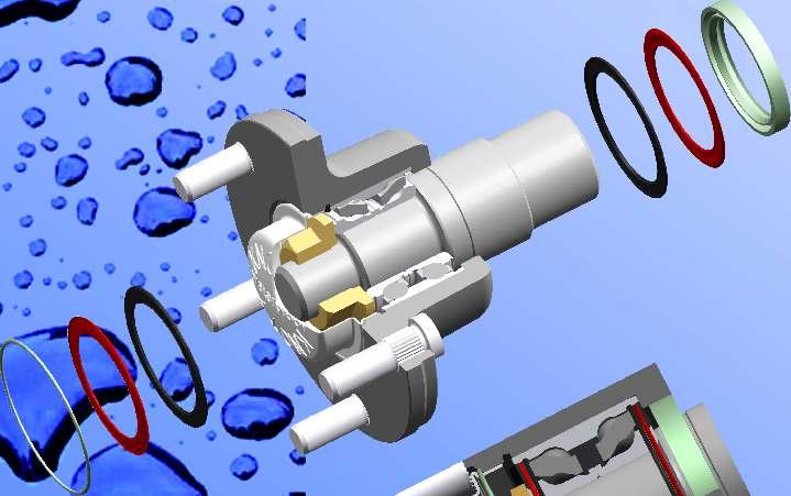
74
75

76 Double row bearing with skew influence line Spindle seal Grease cap seal Heavy duty, maintenance free, water resistant bearings with double skew influence line are applied in our series production axles Connecting to the mechanical characteristics, the skew influence line bearing with ball-row distance of.7 is equivalent to two pieces of bevel roller bearings with roller distance of
77
78 Affix First Class Stamp Here CARLISE TIRE REGISTERY P.O. BOX 570 AKRON, OHIO Affix First Class Stamp Here SEND COMPLETED CARD TO: KENDA USA 7095 Americana Parkway Reynoldsburg, OH


79 KARAVAN TRAILERS P.O. BOX 27 FOX LAKE, WISCONSIN PLACE STAMP HERE
OWNER S MANUAL AND USER S INSTRUCTIONS
 OWNER S MANUAL AND USER S INSTRUCTIONS MODELS A-60, A-75, XR-84, A-84 & A-84 (AC) HYDRAULIC BRAKE ACTUATORS A-60 2" ball A-75 2" ball XR-84 2" ball A-84 2 5 /16" ball A-84(AC) Breakaway cable clips See
AND USER'S INSTRUCTIONS
 OWNER'S MANUAL AND USER'S INSTRUCTIONS MODEL A-60 HYDRAULIC BRAKE ACTUATOR _'_ rnoducts San Marcos, CA * Winchester, TN CONTENTS WARNINGS... INTRODUCTION... HOW TO INSTALL THE ACTUATOR... 3 BLEEDING OF
Installation Instructions and Service Manual
 Installation Instructions and Service Manual Model 80 Actuator* for Trailer Brakes 8,00 lbs Capacity Drum Brake Ready Disc Brake Ready US Patents: 6,37,2 and 8,342,9 *Model 80 - Manufactured after March
Installation Instructions and Service Manual
 Installation Instructions and Service Manual Model 66 Actuator* for Trailer Brakes 6600 lbs Capacity Part #47210/86167 - Drum Brake Ready Part #47211/86165 - Disc Brake Ready *US Patent No. 6,375,211 MODEL
Trailer Brake System Bleeding Procedure:
 Trailer Brake System Bleeding Procedure: The procedure immediately below assumes that a power bleeder will be used. Two people will be required to bleed the brakes if bleeding is to be performed conventionally
Model 80 & 80E Actuator* for Trailer Brakes 8000 lbs Capacity Part #47206/ Drum Brake Ready Part #47208/ Disc Brake Ready
 Installation Instructions and Service Manual For Serial Numbers 6020 and above. Model 80 & 80E Actuator* for Trailer Brakes 8000 lbs Capacity Part #47206/47207 - Drum Brake Ready Part #47208/47209 - Disc
Model 66/660* Actuator for Trailer Brakes 6,600 lbs Capacity Drum Brake Ready or Disc Brake Ready US Patent No. 6,375,211
 Installation Instructions and Service Manual Model 66/660* Actuator for Trailer Brakes 6,600 lbs Capacity Drum Brake Ready or Disc Brake Ready US Patent No. 6,375,211 *Model 660 - Manufactured after March
Heavy Duty Bottle Jacks
 Heavy Duty Bottle Jacks Models: 10300 & 10500 10300 10500! This is the safety alert symbol. It is used to alert you to potential personal injury hazards. Obey all safety messages that follow this symbol
Hydraulic Wheel Dolly
 Hydraulic Wheel Dolly Operating Instructions & Parts Manual Model Number HW93766 Capacity 3/4 Ton Made in the U.S.A. This is the safety alert symbol. It is used to alert you to potential personal injury
Installation Instructions and Service Manual
 Installation Instructions and Service Manual Model 700LP/750LP (Low Profile) Actuator* for Trailer Brakes 7,000/7,500 lbs. Capacity Drum Brake Ready/Disc Brake Ready *US Patent No. 6,375,211 MODEL 700LP/750LP
LC I LIPPERT COMPONENTS DISC BRAKE SYSTEM FOR TRAILERS INSTALLATION, OPERATION & SERVICE MANUAL. Table of Contents
 LC I LIPPERT COMPONENTS DISC BRAKE SYSTEM FOR TRAILERS INSTALLATION, OPERATION & SERVICE MANUAL Table of Contents Introduction... 2 Safety Information... 2 Installation... 3 Solenoid Reversing Valves...
Surge Brake Troubleshooting Tips
 Surge Brake Troubleshooting Tips Surge Brake Troubleshooting Tips Think Safety!! Don t attempt working on your brakes if you aren t experienced with brake systems. These troubleshooting tips assume a person
Service Information for. DISC BRAKES Model db35
 Service Information for DISC BRAKES Model db35 TRAILERING WITH DISC BRAKES Disc brakes offer several advantages over drum brakes that you will appreciate. Disc brakes have improved resistance to fade on
Model 660E Brake Actuator Owner s Manual
 Model 660E Brake Actuator Owner s Manual Installation Instructions and Service Manual Model 660E Actuator for Trailer Brakes 6,600 lbs. Capacity Drum or Disc Brakes Table of Contents Page Actuator Installation
Air Actuated Hydraulic Bottle Jacks
 Air Actuated Hydraulic Bottle Jacks Operating Instructions & Parts Manual Model Number Atd-7412 Atd-7420 Capacity 12 Ton 20 Ton Atd Tools Inc. 160 Enterprise Drive, Wentzville MO 63385 Printed in China
Operating Instructions & Parts Manual
 Swift Lift Hydraulic Service Jack Operating Instructions & Parts Manual Model Number ATD7341 Capacity 3-1/2 Ton U.S. Patent No's. 5,946,912 6,199,379! This is the safety alert symbol. It is used to alert
A Leader in Trailer Transportation OWNER S MANUAL
 Karavan an Trailers, Inc. A Leader in Trailer Transportation OWNER S MANUAL Enclosed is operator s instructions and warranty information for your new Karavan Trailer. Please read them carefully before
BRAKE SYSTEM Return To Main Table of Contents
 BRAKE SYSTEM Return To Main Table of Contents GENERAL... 2 BRAKE PEDAL... 10 MASTER CYLINDER... 13 BRAKE BOOSTER... 16 BRAKE LINE... 18 PROPORTIONING VALVE... 19 FRONT DISC BRAKE... 20 REAR DRUM BRAKE...
Hydraulic Wheel Dolly
 Hydraulic Wheel Dolly Operating Instructions & Parts Manual Model Number HW93765 Capacity 3/4 Ton Made in the U.S.A. This is the safety alert symbol. It is used to alert you to potential personal injury
Low Profile Service Jack
 Low Profile Service Jack Model GMG29031 Capacity 3 Ton U.S. Patent No. 6,199,379! This is the safety alert symbol. It is used to alert you to potential personal injury hazards. Obey all safety messages
Fast Lift Service Jack, Low Profile
 Blackhawk Automotive is a Licensed Trade Mark Made by SFA Companies, Kansas City, MO Fast Lift Service Jack, Low Profile Operating Instructions & Parts Manual Model BH6023B Capacity 2 Ton! U.S. Patent
Operating Instructions & Parts Manual
 Aluminum / Steel Hybrid Service Jack Operating Instructions & Parts Manual Model 26017 26028 26033 Capacity 1.5 Ton 2.5 Ton 3 Ton! This is the safety alert symbol. It is used to alert you to potential
MagicLift Hydraulic Service Jack Model (w/one piece handle) (w/one piece handle)
 (w/one piece handle)") Operating Instructions & Parts Manual MagicLift Hydraulic Service Jack Model 27025 27026 (w/one piece handle) 27035 27036 (w/one piece handle) Capacity 2-1/2 Ton 2-1/2 Ton 3-1/2 Ton 3-1/2 Ton Model 27025
Operating Instructions & Parts Manual MagicLift Hydraulic Service Jack Model 27025 27026 (w/one piece handle) 27035 27036 (w/one piece handle) Capacity 2-1/2 Ton 2-1/2 Ton 3-1/2 Ton 3-1/2 Ton Model 27025
MANUAL SERVICE MANUAL FOR HYDRASTAR HYDRAULIC TRAILER BRAKE ACTUATORS
 MANUAL 440-1008 SERVICE MANUAL FOR HYDRASTAR HYDRAULIC TRAILER BRAKE ACTUATORS THIS DOCUMENT TO BE USED FOR HBA-10, HBA-12, HBA-16, MHBA-10, MHBA-12, MHBA-16 ACTUATORS ECN 04007 Manual 440-1008 Rev E Page
TITAN MODEL 6 SURG-O-MATIC ACTUATOR FOR TRAILER BRAKES
 INSTALLATION INSTRUCTION AND SERVICE MANUAL Actuator/Trailer Dealer - Please provide these instructions to the consumer. Consumer - Read and follow these instructions. Keep them with the trailer for future
Low Profile Service Jack Jack Stand Combo
 Low Profile Service Jack Jack Stand Combo Jack Stands Low Profile Service Jack U.S. Patent No. 6,199,379! This is the safety alert symbol. It is used to alert you to potential personal injury hazards.
Heavy Duty Engine Cranes
 Heavy Duty Engine Cranes Operating Instructions & Parts Manual Model Number Atd-7484 Atd-7485 (Foldable Legs) Capacity 2 Ton 2 Ton Model Atd-7484 Model Atd-7485 Atd Tools Inc. 160 Enterprise Drive, Wentzville,
Hydraulic Truck Jack
 Operating Instructions & Parts Manual Hydraulic Truck Jack Model Capacity 23221C 22 Ton 23222C (Low Profile) 22 Ton 23301 30 Ton Models 23221C & 23222C Model 23301! U.S. Patent No's. 5,341,723 & 5,94,912
Long Chassis Hydraulic Service Jacks
 Model BH6011 Long Chassis Hydraulic Service Jacks Operating Instructions and Parts Manual Capacity 10 Ton Model BH6011 U.S. Patent No's. 5,946,912 5,341,723! This is the safety alert symbol. It is used
3/16 BC20001, Rev 6. Brakes. free-backing ASSEMBLY CALIBRATION OPERATION REPLACEMENT PARTS. Page 1
 3/16 BC20001, Rev 6 Brakes free-backing UNI-servo ASSEMBLY CALIBRATION OPERATION REPLACEMENT PARTS Page 1 WARRANTY POLICY, OPERATOR MANUALS & REGISTRATION Go online to www.demco-products.com to review
Long Chassis Hydraulic Service Jacks
 Long Chassis Hydraulic Service Jacks Operating Instructions & Parts Manual Model Number Atd-7390 Atd-7391 Capacity 5 Ton 10 Ton Atd Tools Inc. 160 Enterprise Drive, Wentzville MO 63385 Printed in China
Low Profile Service Jack
 Low Profile Service Jack Operating Instructions & Parts Manual Model Number JSA200LCX Capacity 2 Ton MAC TOOLS INC. 2005 505 N. Cleveland Ave. Suite 200 Westerville, OH 43082 Printed in PRC Save these
INSTALLATION INSTRUCTIONS
 INSTALLATION INSTRUCTIONS DISC BRAKE CONVERSION KITS A121-1, A121-2, A121-3, A121-4 1967-69 Ford & Mercury Thank you for choosing STAINLESS STEEL BRAKES CORPORATION for your braking needs. Pleases take
TITAN AERO 7500 ACTUATOR FOR TRAILER BRAKES INTRODUCTION TO SURGE BRAKING
 INSTALLATION INSTRUCTION AND SERVICE MANUAL Actuator/Trailer Dealer - Please provide these instructions to the consumer. Consumer - Read and follow these instructions. Keep them with the trailer for future
INSTALLATION INSTRUCTIONS
 INSTALLATION INSTRUCTIONS REAR DISC BRAKE CONVERSION KIT A126-1 1973-87 CHEVROLET 1/2 TON 2WD Thank you for choosing STAINLESS STEEL BRAKES CORPORATION for your braking needs. Pleases take the time to
Heavy Duty Jack Stands
 Heavy Duty Jack Stands Operating Instructions & Parts Manual Made in the U.S.A. Model Number HW93511 Capacity per pair 10 Ton Model Number HW93512 Capacity per pair 10 Ton This is the safety alert symbol.
Hydraulic Transmission Jack, Telescopic
 Operating Instructions & Parts Manual Hydraulic Transmission Jack, Telescopic Model 4000 400 (Air Operated) Capacity 000 lbs. 000 lbs. Model 4000 Model 400 U.S. Patent No. 6,02,377! This is the safety
Operating Instructions & Parts Manual. Air/Manual Hydraulic Bottle Jacks
 J18124-M1_032015 Operating Instructions & Parts Manual Air/Manual Hydraulic Bottle Jacks Model J18124 J18204 Capacity 12 Ton 20 Ton U.S. Patent Nos. 6,012,377-5,946,912! This is the safety alert symbol.
Atd Tools Inc. 160 Enterprise Drive, Wentzville, MO 63385
 Owner's Manual Garage Jack Model RHO-10113 Capacity 3 Ton This is the safety alert symbol. It is used to alert you to potential personal injury hazards. Obey all safety messages that follow this symbol
Engine Crane Owner s Manual
 Engine Crane Owner s Manual Model Number ATD04 Capacity Ton WARNING: This product may contain chemicals, including lead, known to the State of California to cause cancer, birth defects or other reproductive
Air Actuated Hydraulic Bottle Jack on Wheels
 Operating Instructions & Parts Manual Air Actuated Hydraulic Bottle Jack on Wheels Model Number 18127 18207 Capacity 12 Ton 20 Ton Shinn Fu Co. of America, Inc. 2002 10939 N. Pomona Avenue Kansas City,
Hydraulic Transmission Jacks
 Hydraulic Transmission Jacks Operating Instructions & Parts Manual Model Number Atd-7435 Atd-7436 Atd-7437 Capacity 1100 Lb. 2000 Lb. 3000 Lb. Model Atd-7435 Model Atd-7436 Model Atd-7437 Atd Tools Inc.
3/18 BC20002, Rev 7. Brakes ASSEMBLY CALIBRATION OPERATION REPLACEMENT PARTS. Page 1
 3/8 BC000, Rev 7 Brakes ASSEMBLY CALIBRATION OPERATION REPLACEMENT PARTS Page WARNING: To Prevent Serious Injury or Death Failure to follow these instructions, or failure to properly maintain brakes after
Hydraulic Long Jacks
 Operating Instructions & Parts Manual Hydraulic Long Jacks Model 44915 44930 44940 44980 44981C (Air option) Capacity 1-1/2 Ton 3 Ton 4 Ton 8 Ton 8 Ton Models 44915, 44930, 44940 & 44980 Model 44981C U.S.
INSTALLATION INSTRUCTIONS
 INSTALLATION INSTRUCTIONS DISC BRAKE CONVERSION KITS A120-4 & A120-5 1964-1/2-66 Ford & Mercury Thank you for choosing STAINLESS STEEL BRAKES CORPORATION for your braking needs. Pleases take the time to
Parking brake Mechanical brake acting on rear wheels
 11 Brake System 11.1 General SPECIFICATIONS EJTC0010 Master cylinder Type Tandem type I.D. mm(in.) 20.64 mm (0.813 in.) Fluid level warning sensor Provided Brake booster Type Vacuum Boosting ratio 4.0
Atd Tools Inc. 160 Enterprise Drive, Wentzville, MO 63385
 Owner's Manual Trolley Jack Model ATD-7304 Capacity 2 Ton! This is the safety alert symbol. It is used to alert you to potential personal injury hazards. Obey all safety messages that follow this symbol
Hydraulic Clutch Jack
 Hydraulic Clutch Jack Operating Instructions & Parts Manual Model Number Atd-7404 Capacity 500 Lb. Atd Tools Inc. 160 Enterprise Drive, Wentzville MO 63385 Printed in China ATD7404-M0 05/07 Save these
Operating Instructions & Parts Manual. Hydraulic Bottle Jacks
 Operating Instructions & Parts Manual Hydraulic Bottle Jacks Models: 1005C, 10045C, 10065C, 10085C, 1015C, 1019C, 1005C, 1009C & 1000 This is the safety alert symbol. It is used to alert you to potential
CAUTION. Hydraulic Brakes. Braking Systems - Hydraulic
 Hydraulic Brakes Dexter offers several varieties of hydraulic trailer brakes. Your vehicle may be equipped with drum brakes or disc brakes. The hydraulic brakes on your trailer are much like those on your
3/4 Ton Heavy Duty Wheel Dolly
 3/4 Ton Heavy Duty Wheel Dolly Operating Instructions & Parts Manual BH8075 SFA Companies 2004 10939 N. Pomona Ave. Kansas City, MO 64153 816-891-6390 sales@blackhawk-automotive.com - Before using this
TRAILER OWNER S MANUAL
 This manual is designed to provide information for you to understand, use, maintain and service your Triton trailer. Additional help and replacement parts are available through your local dealer. TRAILER
INSTALLATION INSTRUCTIONS
 INSTALLATION INSTRUCTIONS DISC BRAKE CONVERSION KIT A120-20, A120-21 1964 1 /2-66 Ford & Mercury Thank you for choosing STAINLESS STEEL BRAKES CORPORATION for your braking needs. Pleases take the time
Eliminator Vented Disc Brakes Owners Manual
 Eliminator Vented Disc Brakes Owners Manual TIE DOWN ENGINEERING 255 Villanova Drive SW, Atlanta, GA 30336 www.tiedown.com (404) 344-0000 Fax (404) 349-0401 2008 TIE DOWN INC. ALL RIGHTS RESERVED Instruction
Heavy Duty Engine Cranes
 Heavy Duty Engine Cranes Operating Instructions & Parts Manual Model Number ATD-7484 ATD-7485 (Foldable Legs) Capacity 2 Ton 2 Ton Model ATD-7484 Model ATD-7485 WARNING: This product may contain chemicals,
1250 LB. CAPACITY MECHANICAL WHEEL DOLLY
 1250 LB. CAPACITY MECHANICAL WHEEL DOLLY 67287 SET-UP AND OPERATING INSTRUCTIONS Visit our website at: http://www.harborfreight.com Read this material before using this product. Failure to do so can result
Operating Instructions & Parts Manual
 Operating Instructions & Parts Manual MagicLift Service Jack, Low Profile Model 29023 29025 Capacity 2 Ton 2 Ton 29023 29025 U.S. Patent No s. 6,199,379 5,946,912! This is the safety alert symbol. It is
BX7322 Adventurer Tow Bar Operator Manual & Installation Instructions
 Please visit www.blueox.com for the latest version of these installation instructions. BX7322 Operator Manual & Installation Instructions Serial Number (5,000 lb) 2 Inch Coupler 292-1263 Rev J Page 1 of
Brakes. FREE BACKING # Right # Left. UNI-SERVO # Right # Left. Page 1. 1/15 BC20011, Rev 6
 1/15 BC20011, Rev 6 Brakes FREE BACKING #01971 - Right #01970 - Left UNI-SERVO #07911 - Right #07910 - Left ASSEMBLY CALIBRATION OPERATION REPLACEMENT PARTS Page 1 WARNING: To Prevent Serious Injury or
Premium Supply. Direct Push. Models PCK-3530-DP PCK DP PCK-530-DP. Operator s Manual and Installation Instructions
 Direct Push Models PCK-3530-DP PCK-3530-2DP PCK-530-DP Operator s Manual and Installation Instructions Premium Supply 2038 West Interstate 30 866-934-0777 Proud members of: and June 20, 2018 Table of Contents
TITAN MODEL 60 SURG-O-MATIC ACTUATOR FOR TRAILER BRAKES
 INSTALLATION INSTRUCTION AND SERVICE MANUAL Actuator/Trailer Dealer - Please provide these instructions to the consumer. Consumer - Read and follow these instructions. Keep them with the trailer for future
Eliminator Vented Disc Brakes Owners Manual
 Eliminator Vented Disc Brakes Owners Manual TIE DOWN ENGINEERING 255 Villanova Drive SW, Atlanta, GA 30336 www.tiedown.com (404) 344-0000 Fax (404) 349-0401 Instruction Sheet #08075 101310,C752 Eliminator
Magic Lift TM Hydraulic Service Jacks Operating Instructions & Parts Manual
 Blackhawk Automotive is a Licensed Trade Mark Made by SFA Companies, Kansas City, MO Magic Lift TM Hydraulic Service Jacks Operating Instructions & Parts Manual Model BH6057 BH6107 Capacity 5 Ton 10 Ton
TITAN 13 x 2½ BRAKES DUO-SERVO AND FREE BACKING
 INSTALLATION INSTRUCTION AND SERVICE MANUAL Actuator/Trailer Dealer - Please provide these instructions to the consumer. Consumer - Read and follow these instructions. Keep them with the trailer for future
Service Jacks Operating Instructions & Parts Manual
 Service Jacks Operating Instructions & Parts Manual Model Number HW93642 HW93652 Capacity 2 Ton 3 Ton Made in the U.S.A. This is the safety alert symbol. It is used to alert you to potential personal injury
Operating Instructions & Parts Manual. MagicLift Hydraulic Service Jack
 Operating Instructions & Parts Manual MagicLift Hydraulic Service Jack Model: 25023 Capacity: 2 Ton This is the safety alert symbol. It is used to alert you to potential personal injury hazards. Obey all
ULTRA WEIGHT DISTRIBUTING HITCH SYSTEM INSTALLATION/OPERATION INSTRUCTIONS
 ULTRA-FAB PRODUCTS, INC. 57985 St. Rd. 19 South, Elkhart, Indiana 46517 ULTRA WEIGHT DISTRIBUTING HITCH SYSTEM ULTRA WEIGHT DISTRIBUTING HITCH SYSTEM INSTALLATION/OPERATION INSTRUCTIONS ITEM # 1 EXPLODED
PREMIER, MARINE, & STANDARD
 INSTA LLATION INSTRUCTION AND SERVICE MANUAL I TITAN 12" x 2" BRAKES FREE BACKING. UNI-SERVO. DUO-SERVO PREMIER, MARINE, & STANDARD Limited Warranty TITAN Inc. ("TITAN') warrants its products to be free
INSTALLATION INSTRUCTIONS
 INSTALLATION INSTRUCTIONS PERFORMANCE AT THE WHEELS KITS W156-6 & W156-7 1965-74 MOPAR B & E BODY Thank you for choosing STAINLESS STEEL BRAKES CORPORATION for your braking needs. Pleases take the time
INSTALLATION INSTRUCTIONS
 INSTALLATION INSTRUCTIONS REAR DISC BRAKE CONVERSION KIT A158 1994-97 Dodge Ram 1500 (2WD & 4WD) and REAR DISC BRAKE CONVERSION KIT A158-1 1998-01 Dodge Ram 1500 (2WD & 4WD) Thank you for choosing STAINLESS
GORE TRAILER MANUFACTURING INCORPORATED 305 Gore Trailer Road Whiteville, North Carolina 28472
 (Revised September, 2005) GORE TRAILER MANUFACTURING INCORPORATED 305 Gore Trailer Road Whiteville, North Carolina 28472 WARRANTY TEN YEAR WARRANTY Subject to the requirements, exclusions and limitations
Operating Instructions & Parts Manual. MagicLift Hydraulic Service Jack
 Operating Instructions & Parts Manual MagicLift Hydraulic Service Jack Model 27035 27036 (w/one piece handle) Capacity 3-1/2 Ton 3-1/2 Ton Model 27035! This is the safety alert symbol. It is used to alert
Operating Instructions & Parts Manual. Capacity 2 Ton 3 Ton
 Service Jacks Operating Instructions & Parts Manual Model Number HW93642 HW93652 Capacity 2 Ton 3 Ton Made in the U.S.A. This is the safety alert symbol. It is used to alert you to potential personal injury
DISC BRAKE/DUAL MASTER CYLINDER CONVERSION. Tools, Equipment and Supplies Needed:
 Please take the time to read the enclosed instructions carefully. If you have any questions, call our Product Assistance personnel for clarification. It is important to note that these instructions contain
Installation Instructions
 Preparing your vehicle to install your brake system upgrade 1. Rack the vehicle. 2. If you don t have a rack, then you must take extra safety precautions. 3. Choose a firmly packed and level ground to
Fast Lift Hydraulic Service Jack
 Fast Lift Hydraulic Service Jack Operating Instructions & Parts Manual Model Number ATD-7314 Capacity 3.5 Ton U.S. Patent No's. 5,946,912 6,199,379! This is the safety alert symbol. It is used to alert
BX7322 Adventurer Tow Bar Operator Manual & Installation Instructions
 Please visit www.blueox.com for the latest version of these installation instructions. BX7322 Operator Manual & Installation Instructions Serial Number (5,000 lb) 2 Inch Coupler 292-1263 Rev J Page 1 of
TRAILER WINCH MODELS ST315 AND ST712. General Safety (Continued) Description. Unpacking. General Safety Information.
 Description. Unpacking. General Safety Information.") OPERATION AND MAINTENANCE MANUAL TRAILER WINCH READ CAREFULLY BEFORE ATTEMPTING TO ASSEMBLE, INSTALL, OPERATE OR MAINTAIN THE PRODUCT DESCRIBED. PROTECT YOURSELF AND OTHERS BY OBSERVING ALL SAFETY INFORMATION.
OPERATION AND MAINTENANCE MANUAL TRAILER WINCH READ CAREFULLY BEFORE ATTEMPTING TO ASSEMBLE, INSTALL, OPERATE OR MAINTAIN THE PRODUCT DESCRIBED. PROTECT YOURSELF AND OTHERS BY OBSERVING ALL SAFETY INFORMATION.
Owner s Manual & Safety Instructions
 Owner s Manual & Safety Instructions Save Save This This Manual Keep Keep this this manual manual for for the the safety safety warnings warnings and and precautions, assembly, assembly, operating, inspection,
BX Jeep Liberty Renegade 2012 Jeep Liberty Sport Installation Instructions
 Attachment Tab Height: 17.5 Attachment Tab Width: 24 Serial Number Please read BOTH these and the General Instructions prior to installing or operating this equipment. 1. Blue Ox towing products and accessories
Operating Instructions & Parts Manual. MagicLift Hydraulic Service Jack
 Operating Instructions & Parts Manual MagicLift Hydraulic Service Jack Model 25057 25107 Capacity 5 Ton 10 Ton This is the safety alert symbol. It is used to alert you to potential personal injury hazards.
Model 315. Always stand clear of the area behind and between the load or anchor point and the winch. Serious injury could occur, if the cable breaks.
 315, 712A and 912 Please read and save these instructions. Read carefully before attempting to assemble, install, operate or maintain the product described. Protect yourself and others by observing all
INSTALLATION INSTRUCTIONS
 INSTALLATION INSTRUCTIONS PERFORMANCE AT THE WHEELS KIT W120-22, W120-23 1964 1/2-69 MUSTANG Thank you for choosing STAINLESS STEEL BRAKES CORPORATION for your braking needs. Pleases take the time to read
BX7445 Aventa LX Tow Bar Operator Manual & Installation Instructions
 Please visit www.blueox.com for the latest version of these installation instructions. BX7445 Operator Manual & Installation Instructions Serial Number (10,000 lb) 2 Inch Receiver 292-2938 Rev D Page 1
FRICTION SWAY CONTROL OWNER S MANUAL
 FRICTION SWAY CONTROL OWNER S MANUAL WARNING: Read carefully and understand all INSTRUCTIONS before operating. Failure to follow the safety rules and other basic safety precautions may result in serious
TITAN MODEL 20 SURG-O-MATIC ACTUATOR FOR TRAILER BRAKES , , , INTRODUCTION TO SURGE BRAKING
 INSTALLATION INSTRUCTION AND SERVICE MANUAL Actuator/Trailer Dealer - Please provide these instructions to the consumer. Consumer - Read and follow these instructions. Keep them with the trailer for future
12. FRONT WHEEL/FRONT BRAKE/
 12 4.5kgm 0.9kg-m 4.5kg-m 12-0 SERVICE INFORMATION... 12-1 HYDRAULIC BRAKE... 12-10 TROUBLESHOOTING... 12-2 FRONT SHOCK ABSORBER... 12-16 FRONT WHEEL... 12-3 STEERING HANDLEBAR... 12-19 FRONT BRAKE...
Venture Trailers We take the world boating. visit Venture Trailers online:
 Venture Trailers We take the world boating. visit Venture Trailers online: www.venturetrailers.com Trailer Features: Corrosion resistant fasteners Larger than industry standard bunks Heavy duty winch straps
INSTALLATION INSTRUCTIONS
 INSTALLATION INSTRUCTIONS POWER FRONT DISC CONVERSION KIT A126-7 1963-66 CHEVY C10 PICKUP NON-POWER FRONT DISC CONVERSION KIT A126-8 1963-72 CHEVY C10 PICKUP Thank you for choosing STAINLESS STEEL BRAKES
DESCRIPTION & OPERATION
 2004 BRAKES Disc - TSX DESCRIPTION & OPERATION WARNING: DO NOT use air pressure or a dry brush to clean brake assemblies. Avoid breathing brake dust. Use OSHA-approved vacuum cleaner for cleaning and collecting
NATIONAL HIGHWAY TRAFFIC SAFETY ADMINISTRATION (NHTSA)
") NATIONAL HIGHWAY TRAFFIC SAFETY ADMINISTRATION (NHTSA) If you believe that your vehicle has a defect which could cause a crash or could cause injury or death, DO NOT USE THE VEHICLE. You should immediately
NATIONAL HIGHWAY TRAFFIC SAFETY ADMINISTRATION (NHTSA) If you believe that your vehicle has a defect which could cause a crash or could cause injury or death, DO NOT USE THE VEHICLE. You should immediately
INSTALLATION INSTRUCTIONS
 INSTALLATION INSTRUCTIONS REAR DISC CONVERSION KIT A128-4 1997-2004 JEEP WRANGLER (TJ) WITH DANA 44 AXLES (non-abs) Thank you for choosing STAINLESS STEEL BRAKES for your braking needs. Pleases take the
INSTALLATION INSTRUCTIONS
 INSTALLATION INSTRUCTIONS FRONT BIG BRAKE CONVERSION KIT A112-5 1987-93 FORD MUSTANG Thank you for choosing STAINLESS STEEL BRAKES CORPORATION for your braking needs. Pleases take the time to read and
INSTALLATION INSTRUCTIONS
 INSTALLATION INSTRUCTIONS REAR DISC CONVERSION KIT A126-2 1988-98 C1500 2WD 10" REAR DRUM Thank you for choosing STAINLESS STEEL BRAKES CORPORATION for your braking needs. Pleases take the time to read
INSTALLATION INSTRUCTIONS
 INSTALLATION INSTRUCTIONS REAR DISC BRAKE CONVERSION KITS A112, A112-1 & A112-93 1979-93 FORD MUSTANG with 7.5" & 8.8" AXLES Thank you for choosing STAINLESS STEEL BRAKES CORPORATION for your braking needs.
580RK SERVICE GUIDELINES For coupling models: 580 & 580J
 580 Coupling THE FIRST NAME IN QUALITY COUPLINGS 580RK SERVICE GUIDELINES For coupling models: 580 & 580J BEFORE GETTING STARTED: This procedure should only be performed by a qualified mechanic. Measure
INSTALLATION INSTRUCTIONS R1 REAR CONVERSION KIT
 INSTALLATION INSTRUCTIONS R1 REAR CONVERSION KIT INSTRUCTION FOR ASSEMBLY OF JEEP CJ SERIES W/AMC 20 REAR AXLES, 5 x 5-1/2" BOLT CIRCLE WITH A130-4 FULL FLOATING AXLE OR A130-5 (1 PIECE AXLE) Thank you
G5 Stainless Steel Brakes Owners Manual
 G5 Stainless Steel Brakes Owners Manual Important: Read all of this Stainless Steel Disc Brake Manual before starting installation or removal of any part on the disc brakes. TIE DOWN ENGINEERING 255 Villanova
Dura Force Disc Brake System Service Manual
 TS 20809_a 3501 Shotwell Drive ISO/TS 16949:2002 Registered (PH): 937.743.8125 Franklin, OH 45005 www.waltheremc.com (FX): 937.743.8232 Table of Contents General Description 1 3 Fastener Torque Chart 4
Atd Tools Inc. 160 Enterprise Drive, Wentzville, MO 63385
 Owner's Manual Model RHO-7425 High Lift Transmission Jack Capacity 700 lbs.! This is the safety alert symbol. It is used to alert you to potential personal injury hazards. Obey all safety messages that