NABRICO DF-1 NS Electric Winch Owner s Manual OM-DF1-018-A
|
|
|
- Walter Parker
- 5 years ago
- Views:
Transcription


1 NABRICO DF-1 NS Electric Winch Owner s Manual OM-DF1-018-A
2
3 NABRICO Owner s Manual Upright Electric Winch MODEL # DF-1 (Nord-Stearns) Contents Safety Information...2 Product Information Installation of Winch Electrical Power Connection Installation of Wire Rope Operating the Winch Equipment Inspection Equipment Lubrication Cleaning and Storage...15 Appendix A-Winch Technical Information (shaft mount)...17 Appendix B-Stearns Brake Technical Information...47 Product Warranty...60 NABRICO 1250 GATEWAY DRIVE GALLATIN, TN TEL: (615) FAX: (615) OM-DF1-018-A
4 NOTICE! Prior to installing and operating the winch, please read this manual thoroughly and carefully. Keep this manual and all other instructions accessible at all times. The Occupational Safety and Health Act of 1970 states that it is the employer s responsibility to provide a workplace free of hazard. To this end, all equipment should be installed, operated, and maintained in compliance with applicable trade, industrial, federal, state, and local regulations. It is the equipment owner s responsibility to obtain copies of these regulations and to determine the suitability of the equipment to its intended use. Although this manual will help you become familiar with the basic operation of the winch, it is not a substitute for proper training by your company in the safe use of winches, barge rigging and other marine equipment. This manual suggests methods of operation, but ultimately, the owners and operators of the equipment are responsible for determining whether a particular method of operation is safe and appropriate for the equipment being operated. Only individuals trained in the proper use of winches, barge rigging and other marine equipment should operate these winches. The typical operating environment of barge and towboat winches often includes very high forces, and the potential hazards associated with these high forces should not be underestimated. Improper installation or incorrect or unsafe use could result in injury or death to persons or cause equipment failure or damage. Recommended Information for Safe Operation: 2 Check lubrication before use. Do not apply tension to the winch unless there are at least three complete wraps of rope on the drum. Do not operate the winch unless you have a firm stance on a non-slippery surface. Do not wrap the wire rope around the load. This will damage the wire rope and could cause the load to escape. Rigging connectors are strongly recommended to secure the wire rope to the load. Keep fingers, loose clothing and any foreign objects away while operating the winch. Do not divert attention away while operating the equipment. Stay alert to the possibility of accidents and try to prevent them from happening. Always remain to the side of the winch while in operation. Never operate the winch from the front or when bystanders are in front of it. Operators and bystanders should stay clear of any load and the wire rope while the winch is operating. Avoid shock loads by starting and stopping the equipment smoothly. Shock loads can over load the equipment which may cause damage. Under no circumstances, should any winch be used to move, raise or lower a person(s) or equipment. Do not exceed a 15 minute duty cycle for the winch. To do so may result in equipment damage or failure. NOTICE Inspect the winch carefully at least once a month for loose fasteners, worn gears and pawls, cracked welds, and other damaged parts. If any worn, cracked or damaged parts are found, stop use immediately and remove winch from service until all appropriate repairs are completely made.

5
6 1.1 INSTALLATION OF WINCH NOTICE It is the responsibility of the customer, not the winch manufacturer, to properly locate and install the winch with regard to the safety of those operating the machinery. CAUTION Install the winch in an area where there is ample room to operate the unit without the operator becoming entangled in the cable, lines, chains, winch mechanisms, or other nearby equipment All winches must be installed on a flat, rigid, and non-slippery surface. Deck and structure must be strong enough to withstand the weight and holding capacity of the winch, and the forces likely to occur during operation. A qualified professional should inspect or design the foundation to insure that it will provide adequate support Locate the winch in a suitable area free of traffic and obstacles. The winch should also be visible during entire operation. Keep in mind that the winch needs to be accessible for proper lubrication, maintenance and operation Mounting direction should be in line with the desired direction of cable pull. The front of the winch must face in the direction from which the cable is reeled (see fig. #1). When unit is powered up the drum should rotate so that it reels cable onto the bottom of the drum from the front of the winch. 4
7 1.1.4 Maintain a fleet angle no greater that 1-1/2 degrees from winch drum to lead sheave (see fig. #2). The proper fleet helps to minimize wire rope damage by assisting the wire rope to wind uniformly onto the drum Using sufficient tack welds, secure the base bars to the deck or doubler plate. This will prevent the winch from becoming misaligned from heat distortion during the application of the seal weld Next apply a seal weld to the base bars to permanently secure the winch. The seal weld will prevent corrosion from occurring between the winch and mounting surface Inspect the winch immediately following installation. This inspection will give a good starting record of the winch condition so that future inspections can be compared. CAUTION Remember that the weld must be strong enough to withstand loads equal to or greater than the capacity of the winch. 5
8 PAGE INTENTIONALLY LEFT BLANK 6
9 1.2 ELECTRICAL POWER CONNECTION CAUTION All electrical work must be performed by a licensed electrician. Failure to do so could result in electric shock or poor equipment operation All winches have been factory tested prior to shipment to insure proper operation All winches have been factory wired to accommodate power supplies as specified by the customer Make certain that equipment is grounded before electrical power is connected Refer to Appendix A.3 for typical connection between motor and control box Ensure that the correct power supply agrees with the motor rating before connecting power to the winch. Do not operate the winch until proper power is supplied to the motor Before operation of the winch, remove the plastic plug from the gearbox breather Test connections by operating the winch. The rotation of the drum must agree with the labels of the control device, and the motor must stop when the control is released. The drum must reel the wire rope onto the bottom of the winch drum when the IN button is depressed. 7
10 1.3 INSTALLATION OF WIRE ROPE (Refer to the operation section of this manual if unclear on how to operate the winch.) To install wire rope, rotate the drum of the winch so that the U-bolt nuts are easily accessed through the round cut out located on the side of the winch (see fig. #4a) Using a standard socket wrench with an extension, loosen the nuts If installing wire rope on a new winch, remove and discard the U-bolt spacer pipe. If replacing worn out wire rope, remove the wire rope from the U-bolt and dispose of properly. CAUTION Remember to always wear the proper protective equipment when handling the wire rope Insert the new wire rope end under the winch drum and through the U-bolt from the front of the winch so that approximately 3 to 4 inches extend through the U-bolt (see fig. #4b). NOTICE Breaking strength of new wire rope must be a least 3 times greater than the largest load placed on the winch. This minimum value may be greater depending on type of load and the method of moving the load Tighten the U-bolt nuts evenly to secure the wire rope to the winch drum. The U-bolt will act as a clamp keeping the wire rope in place as the rest of the rope is reeled onto the winch. CAUTION The U-bolt nuts must be retightened periodically to insure that the wire rope end is held in place snugly against the drum flange. Over time and usage the rope will crush down at the U-bolt creating the possibility that the rope will escape. 8
11 1.3.6 Wind the wire rope onto the drum by operating the winch. Maintain tension on the wire rope to insure that the first coil lays snugly against the drum flange and each successive coil is snug against the previous coil. Make sure that the wire rope is being reeled in from the bottom on the winch drum Continue wrapping the wire rope until there are at least 3 to 4 complete wraps on the winch drum. These wraps serve as an anchor and must remain on the drum at all times. WARNING In order for the winch to attain its full holding capacity, 3 to 4 complete wraps of the wire rope must be on the winch drum at all times. Also, make sure the rope is installed securely to the drum. A poorly secured wire rope could come loose from its anchor and allow the load to escape. NOTICE Drum capacity depends on how tightly and evenly the wire rope is wound on the drum. Actual drum capacities are usually 25% to 30% less than values given in performance tables when the wire rope is loosely wound and overlapping. Also, line speed will increase with each additional layer of wire rope that is wound onto the drum. 9
12 2.1 OPERATING THE WINCH The DF-1 Upright Winch is an electrically driven system. The following operating instructions will help you become familiar with the basic operating components of the winch; it is by no means a substitute for proper training by your company in the safe use of winches, barge rigging, and other marine equipment. CAUTION Under no circumstances should the winch be used to raise or lower personnel. CAUTION Before operating make certain all personnel are clear of the deck area surrounding the winch. Notify all personnel that the winch is ready for use To reel the wire rope onto the winch drum, depress and hold the IN button located on the control box or remote operator station. Make certain that the locking pawl is disengaged by rotating the locking pawl handle to the up position and inserting the T handle locking pin to secure in place (see fig. #5a) Observe the wire rope as it winds onto the winch drum. If it becomes loose, uneven, or overlapped, stop the operation and rewind before continuing. Continued operation with undesirable wire rope lay can damage the rope and shorten its life. 10
13 2.1.3 To reel the wire rope off the winch drum, depress and hold the OUT button located on the control box or remote operator station. Some tension should be kept on the wire rope during unreeling to minimize rope fouling on the drum. CAUTION Length of winch operation should not exceed the 15 minute duty cycle rating. NOTICE Breaking in the winch occurs during the first 30 to 60 minutes. During break-in, mating surfaces become polished and clearances increase. This is desirable for efficient operation of the bearings and gears To stop the wire rope, release the IN or OUT button; this will automatically engage the electric brake located on the winch motor. As with any electric brake, there is a slight delay (approx seconds) between the IN or OUT button release and brake set After the winch is stopped and the brake is set, the locking pawl handle can be rotated down so the locking pawl is free to engage thus dogging the winch down (see fig. #5b). 11
14 3.1 EQUIPMENT INSPECTION NOTICE An inspection program should be started as soon as any equipment is put into service. A qualified person should be appointed the responsibility of regularly inspecting the equipment. Written records of inspections are recommended by the manufacturer Frequent Inspection Visually inspect the equipment before each use. Check the equipment for cracks, bending, wear, rust, corrosion, and any other damage. If any problems are discovered, stop use immediately and remove the equipment from service until all appropriate repairs are completely performed Ensure that equipment is properly lubricated. Check the gearbox for signs of leakage and make sure it is filled with the proper lubricant Check to ensure that the foundation is in good condition. Make sure that mounting fasteners and other hardware are tightened securely Check electrical wiring and connections for wear, cuts, corrosion, and other damage Ensure that the wire rope is installed correctly and anchored securely to the drum. Also, check to make sure the wire rope is in good condition While equipment is running, listen for unusual noises and look for signs of damage. Visually inspect the wire rope to ensure that it winds evenly onto drum. Make sure winch responds properly to the control device(s) and that the brake operates correctly Periodic Inspection Periodic inspections should occur every 6 months, whenever equipment is returned to service from storage, if a frequent inspection discovers any damage or poor operation, or any case where the winch may have been over loaded Visually inspect the equipment checking the finish for wear, flaking, or other damage as listed in the frequent inspection plan. Disassembly may be required in order to properly inspect individual components. 12
15 Check the gearbox oil for dirt, metal particles, water, and other signs of contamination by draining a small amount into a clean container Ensure that the gearbox is properly lubricated and replenish if necessary to restore the proper level Be certain the winch is not operating and check the winch drum by moving it with your hands. Check for excessive movement that may be the result of worn or loose gears, bearings, or shafts. Some play is normal while excessive may be the result of overloading Disconnect power and thoroughly inspect electrical equipment for signs of wear, cuts, corroded connections, moisture, burn marks, and other damage Wire Rope Inspection Wire rope inspection should be conducted according to the manufacturer s recommendations or accepted industry standards Inspect the entire length of wire cable for bent or crushed areas, broken or cut wires, corrosion, and other damage Inspect end connections and fittings for corrosion, kinking, crushing, or other damage Check the wire rope diameter for signs of decreased area (see fig. #6). Diameter decrease may be signs of wear and internal degradation in the wire rope. Generally, ropes are manufactured larger than nominal diameter. When placed in service for the first time, diameter can reduce slightly. Minimum diameter specifications can be obtained from the rope manufacturer. FIGURE #6 WIRE ROPE DIAMETER 13
16 3.2 EQUIPMENT LUBRICATION All grease fittings and external gearing should be lubricated using NABRICO s suggested lubricants or similar Drive shaft and drum shaft grease fittings should be lubricated at least once a month under normal conditions and at least once a day under adverse conditions. Lubricate while gears are rotating slowly Drive gear teeth should be coated at least once a month. Application with an aerosol can is recommended for uniform coverage. Graphite or other dry type lubricant should be used instead of gear grease when the winch is subjected to large amounts of foreign material such as coal dust. Always keep gear teeth as free of foreign material as possible. RECOMMENED LUBRICANT FOR USE WITH NABRICO DECK MACHINERY HYDRAULIC OIL (OPEN LOOP) MOBIL DTE-26M SPUR, HELICAL GEARS MOBILGEAR632 PLANETARY REDUCERS MOBILUBE HD 80W 90 MOBILE 600W SUPER CYLINDER OIL ALL WORM GEARS (INCLUDING CONE DRIVE) MIL-L-15019C SYMBOL 6135 MOBILE SCH-634 SYNTHETIC LUBRICANT OPEN GEARING (SPRAY CAN) MOBILTAC E LUBRIPLATE OPEN GEAR SHEILDING GREASE FITTINGS MOBILAX EP #2 LUBRIPLATE MARINE LUBE "A" PRESERVATIVE TREATMENT MOBILARMA 524 Note: Lubricant Manufacturers shown are not exclusive recommendations. Consult your lubricant source for more detailed information about oil selection. 14
17 3.3.1 Cleaning the Equipment 3.3 CLEANING AND STORAGE The equipment should be regularly cleaned to remove dirt and to help prevent rust and corrosion When cleaning, be sure to leave a light film of oil on all surfaces to protect them against the weather. Wipe off excessive amounts of oil to avoid the accumulation of dirt Remove all unnecessary objects from the area surrounding the equipment to prevent hazardous situations from occurring Storing the Equipment Lubricate the equipment as necessary to help prevent rust and corrosion during storage. Add a rust preventive for long term storage Seal the equipment in plastic if possible to help prevent rust, corrosion, and other damage Store the equipment upright in a cool clean place away from corrosive chemicals and moisture Rotate the drum periodically to keep bearing and gear surfaces from becoming lacquered. 15
18 PAGE INTENTIONALLY LEFT BLANK 16
19 A.1 Dimensional (Shaft Mounted) 17
20 18
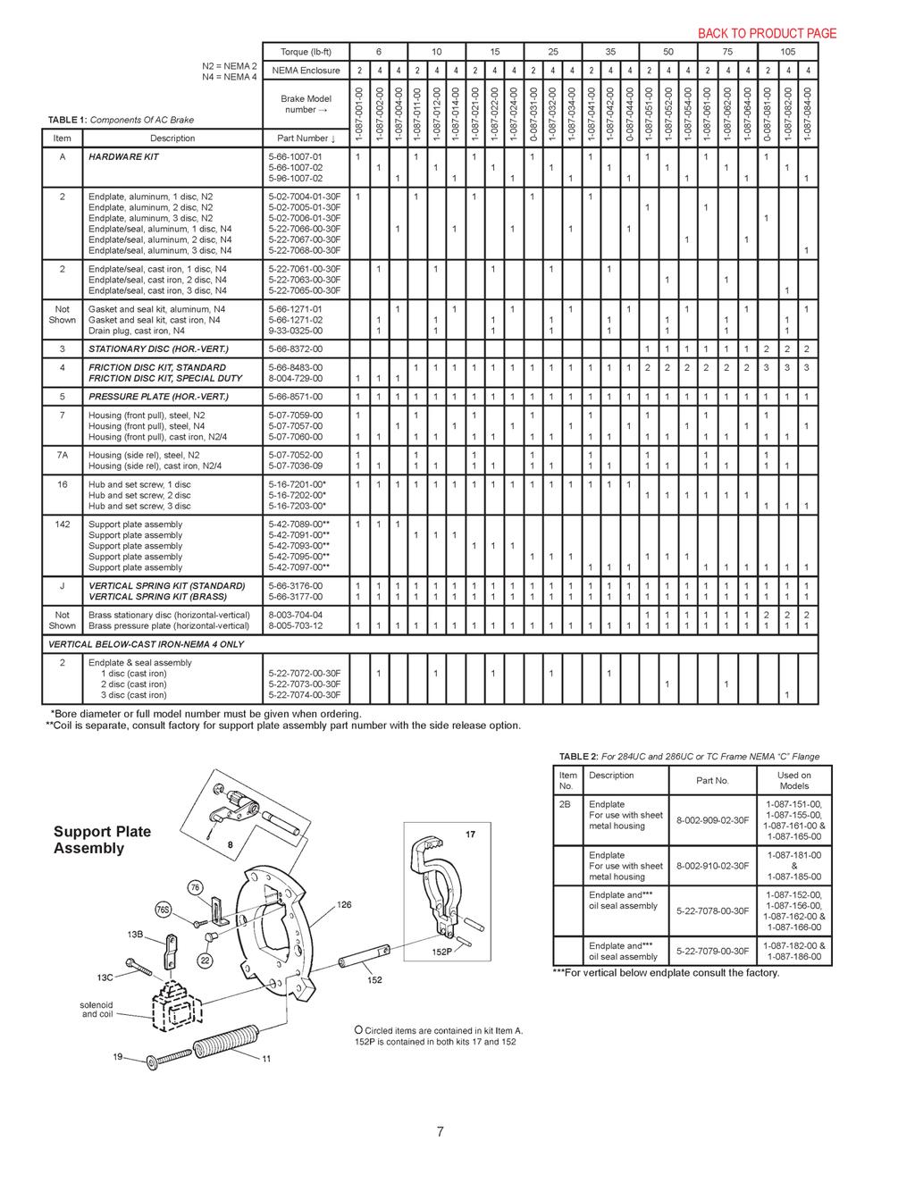
21 DF-1-40/50-NS Electric Winch Parts List DF-1-40/50-NS Electric Winch Parts List Winch Parts Fasteners and Etc. Part Description Qnt'y Part #'s Part Description Qnt'y Part #'s Pipe Separator Hex Nut 3/4" (SS) Drum Shaft Hex Head Bolt 1/2" x 2" (SS) Drum Pipe Spacer Hex Head Bolt 3/4" x 2-1/2" (SS) Drum Washer Hex Nut 7/8" (SS) Intermediate Shaft Lock Washer 7/8" (SS) Intermediate Shaft Collar Socket Head Cap Screw 3/8" x 1" (SS) Intermediate Gear Assembly (Hardened) Locking Pawl Washer Side Plate (keeper side) Washer 9/16" ID x 2-1/2" OD (SS) Side Plate (locking pawl side) Lock Washer 5/8" (SS) Drum Assembly (Hardened) Hex Head Bolt 5/8" x1" Pipe Separator Rod (SS) Socket Head Cap Screw 3/8" x 3" (SS) Drive Pinion Hex Head Bolt 5/8" x 1-3/4" (SS) Key (drive pinion) 1/2" SQ x 4-1/4" Hex Head Bolt 1/2" x 1" (SS) Base Bar Lock Washer 1/2" (SS) Locking Pawl Locking Pawl Post Locking Pawl Sleeve Bushings and Bearings Drive Shaft Part Description Qnt'y Part #'s Locking Pawl Handle (Left Hand Winch) Intermediate Gear Bushing Locking Pawl Handle (Right Hand Winch) Drum Gear Bushing Cover Plate (side mount motor cut-out) Ball Bearing Top Plate Locking Pawl Sleeve Bushing Keeper Plate (BIG) Keeper Plate (small) Miscellaneous Components Cable Guard Plate Part Description Qnt'y Part #'s Drive Shaft Collar HH Bolt (GR8) 5/8" x 4-1/2" Lock Washer (GR8) 5/8" Motor and Components Hex Nut (GR8) 5/8" Part Description Qnt'y Part #'s Cover Mounting Stud 3/8" x 1-1/2" Brake to Motor Adaptor Brass Wing Nut 3/8" Nord Gearmotor (shaft mount) 7.5 hp, ratio Protective Rubber Cover (solid) Nord Gearmotor (shaft mount) 10 hp, ratio U-Bolt with Fasteners (1" Dia. Wire) Stearns Brake (75 ft/lbs, 220/460V) Protective Rubber Cover (cut out) Stearns Brake Hub Torque Arm Spacer T-Handle (locking pawl handle)
22 A.3 Typical Control Box Information 20
23 21
24 22
25 23
26 24
27 25
28 26
29 27
30 28
31 29

32 A.4 Gearmotor Technical Information (Shaft Mounted) 30

33 31

34 32

35 33

36 34

37 35
38 36
39 37
40 38

41 39

42 40
43 41
44 42
45 43
46 44
47 45
48 46

49 B.1 Stearns Model# Electric Brake Technical Information 47
50 48
51 49
52 50

53 51
54 52
55 53
56 54
57 55
58 56
59 57
60 58

61 59

62 PRODUCT WARRANTY NABRICO warrants that all NABRICO products shall be free from defects in material and workmanship during the Warranty Period (as herein defined); provided, however that NABRICO s warranty hereunder shall not apply to any equipment, material or components that is not manufactured by NABRICO, and NABRICO makes no expressed or implied warranty that any such equipment, material or components are free from manufacturer or supplier defects. To the extent doable, NABRICO agrees to transfer and assign to a Buyer or End User any warranties extended by the manufacturer or supplier of such equipment, material or components. NABRICO shall have no obligation or responsibility to repair or replace any defective NABRICO product if a notice of defect is not reported in writing to NABRICO within 180 days from the date of shipment of any NABRICO Winch Products and 90 days from the date of shipment of any other NABRICO Products (such 180 day and 90 day periods are hereinafter referred to as Warranty Period ). In the event Buyer or End User timely notifies NABRICO in writing of any claim of defect covered by this warranty, NABRICO shall correct the nonconforming work by making repairs or replacements, at NABRICO s option and at NABRICO s expense, if NABRICO s examination shall disclose to its satisfaction that all or a portion of the NABRICO Product is defective. However, this warranty is conditional upon compliance by the Buyer or End User with the loading, use and handling in accordance with good commercial practices of the trade, and NABRICO shall not be responsible for defects caused by misleading, overheating, improper cleaning, misapplication, physical abuse or from normal wear and tear. This warranty is void where any NABRICO Product has been altered or repaired by anyone other than NABRICO or its authorized agent. THE WARRANTY AND REMEDIES SET FORTH HEREIN ARE IN SUBSTITUTION OF AND IN LIEU OF ANY AND ALL OTHER WARRANTIES AND REMEDIES EXPRESSED OR IMPLIED, INCLUDING, BUT NOT LIMITED TO, ANY IMPLIED WARRANTIES OF MERCHANTABILITY OR FITNESS FOR A PARTICULAR PURPOSE, WITH RESPECT TO THE CONSTRUCTION, DELIVERY AND SALE OF A NABRICO PRODUCT, AND NABRICO SHALL, FOLLOWING SAID DELIVERY AND SALE, IN NO EVENT BE LIABLE TO BUYER OR ANY END USER FOR THE BREACH OF ANY WARRANTY, GUARANTEE, OR REMEDY, EXPRESSED OR IMPLIED, IN FACT OR IN LAW, EXCEPT AS SPECIFICALLY SET FORTH ABOVE. EXCEPT AS PROVIDED HEREIN, NABRICO SHALL AT NO TIME AND IN NO EVENT BE LIABLE TO BUYER OR ANY END USER OR TO ANYONE CLAIMING TO OR THROUGH BUYER OR ANY END USER FOR LOSS OR DAMAGE OF ANY KIND, INCLUDING, BUT NOT LIMITED TO, ANY ACT, ERROR, OMISSION, NEGLIGENCE, STRICT LIABILITY, TORT, PRODUCT LIABILITY, OR OTHERWISE OF NABRICO, ITS EMPLOYEES OR SUBCONTRACTORS. PRODUCT NOTICES Proprietary Information. The information and sketches shown in this catalog are proprietary to NABRICO. Duplication, reproduction or manufacture from data contained herein is strictly prohibited. Usage Warnings. All NABRICO Products must be correctly sized, properly located and installed to serve their intended functions and it is the responsibility of Buyer or End User to insure such action is taken. Please note and consider the following warnings: Improper installation can result in failure of a NABRICO Product. NABRICO Products that have failed because of overloads, or which have been dislodged from foundations, or have fractures and/or deformations should be repaired or replaced immediately. Loads to bitts must be applied to the posts between the base and the midpoint in a horizontal or downward direction. Properly placed chocks will prevent line chafing. Kevels should be installed horizontally on foundation bases of sufficient size, and forces to kevels must be direct to the trunk and not the horns. Horns will fail when exposed to direct loads. And, NABRICO Products are not designed for use to lift a vessel. Dimensions. All dimensions shown in this catalog are in feet and inches. Weights are in English pounds. Capacities are in short tons of 2,000 pounds. Please note that dimensions and weights are nominal and are subject to standard variations. Maximum test pressure on hatches, doors and enclosures is 2 PSI unless advise in writing by NABRICO of a higher allowance. Product details and specifications are subject to change without notice. 60
63

64 NABRICO 1250 GATEWAY DRIVE GALLATIN, TN fax WINCHES ELECTRIC HYDRAULIC MANUAL HATCHES WATERTIGHT TWIST LOCK QUICK ACTING BITTS DOUBLE BITT SINGLE BITT THRU-DECK BITT CAPSTANS HYDRAULIC ELECTRIC CUSTOMIZABLE DOORS 6 DOG MANUAL QUICK ACTING 4 DOG MANUAL KEVELS KEVEL CHOCK KEVEL THRU-DECK KEVEL SIGNS WARNING CUT-OFF OIL POLLUTION CHOCKS CAST STEEL BUTTON ROLLER BUTTON BARGE CRANES ELECTRIC OPERATION MANUAL OPERATION OIL TANKS 300 GALLON 600 GALLON CUSTOM SIZES OCEAN DOMES MILD STEEL STAINLESS STEEL SUCTION BELLMOUTHS 6 SIZE 8 SIZE 10 SIZE
NABRICO DF-156 HE Winch Owner s Manual OM-DF156-HE-002-C
 NABRICO DF-156 HE Winch Owner s Manual OM-DF156-HE-002-C NABRICO Owner s Manual Hydra-Electric Winch MODEL # DF-156-HE Contents Safety Information...................................... 2 Product Information.....................................
OPERATIONS/PARTS MANUAL FOR PATTERSON'S WWP40E P-L/R ELECTRIC WINCH.
 DOC # A0000298 / A0000299 Patterson Company 870 Riversea Road Pittsburgh, PA 15233 Phone: 800-322-2018 FAX: 412-322-2785 OPERATIONS/PARTS MANUAL FOR PATTERSON'S WWP40E-7.5-14-208-P-L/R ELECTRIC WINCH.
OPERATIONS/PARTS MANUAL FOR PATTERSON'S MODEL # WWP65E ELECTRIC WINCH.
 DOC # 5251-F W. W. Patterson Company 3 Riversea Road Pittsburgh, PA 15233 Phone: 800-322-2018 FAX: 412-322-2785 OPERATIONS/PARTS MANUAL FOR PATTERSON'S MODEL # WWP65E-7.5-14 ELECTRIC WINCH. Please fill
OPERATIONS/PARTS MANUAL FOR PATTERSON'S MODEL # WWP65E ELECTRIC WINCH.
 DOC # 5251-N W. W. Patterson Company 3 Riversea Road Pittsburgh, PA 15233 Phone: 800-322-2018 FAX: 412-322-2785 OPERATIONS/PARTS MANUAL FOR PATTERSON'S MODEL # WWP65E-7.5-14 ELECTRIC WINCH. Please fill
NABRICO PRODUCTS.
 NABRICO PRODUCTS www.nabrico-marine.com CONTENTS Winches Manual... 2-3 Parker... 4 Low Profile... 4 2 and 5 Ton... 5 Specialty... 5 Power... 6-7 Positioning... 8-9 Anchor... 10-11 Capstans Electric...
2008 EDITION.
 2008 EDITION NABRICO PRODUCTS www.nabrico-marine.com CONTENTS Winches Manual... 2-3 Parker... 4 Low Profile... 4 2 and 5 Ton...5 Specialty... 5 Power... 6-7 Positioning... 8-9 Anchor...10-11 Capstans Electric...
OPERATIONS/PARTS MANUAL FOR PATTERSON'S MODEL # WWP50E-5-14 ELECTRIC WINCH.
 W. W. Patterson Company 3 Riversea Road Pittsburgh, PA 15233 Phone: 800-322-2018 FAX: 412-322-2785 OPERATIONS/PARTS MANUAL FOR PATTERSON'S MODEL # WWP50E-5-14 ELECTRIC WINCH. Please fill in the following
PO Box 645, Stockton, Missouri, FAX superiorgearbox.com W D0446-A 4/1/05 1
 W000-7000-D0446-A 4/1/05 1 SAFETY PRECAUTIONS CAUTION Please read this entire document prior to operating the gear drive. Gear drive failure and / or injury to operators may be caused by improper installation,
AC Electric Capstan Owner s Manual Installation and Operating Instructions
 AC Electric Capstan Owner s Manual Installation and Operating Instructions Model: HD2000-1A34-F-01 Serial Number: 123456 VAC _ Ø Hz Line Size: 1/2 CAUTION The final determination as to the suitability
Installation, Operating & Maintenance Manual 30P Planetary Winch
 Installation, Operating & Maintenance Manual 30P Planetary Winch This manual MUST be kept with the winch at all times. New winch operators MUST read and understand the contents fully. WARNING FAILURE TO
20 Gauge Super-Speed. shoprpmachine
 Operator tor s s manual 20 Gauge Super-Speed 1 WARRANTY Our guarantee on the products we manufacture is limited to repair or replacement without charge, of any part found to be defective in materials or
Visit Our Our Our Web Site at:
 Visit Our Our Our Web Site at: ww w ww w w w w. l o c k f o rr r m e r r r. c o m 711 OGDEN AVENUE, LISLE, ILLINOIS 60532-1399 Phone (630) 964-8000 Fax (630) 964-5685 09-1998 Operator tor s manual 20 Gauge
PO Box 645, Stockton, Missouri, FAX superiorgearbox.com
 I000-7000-D0447-A 4/7/05 1 SAFETY PRECAUTIONS CAUTION Please read this entire document prior to operating the gear drive. Gear drive failure and / or injury to operators may be caused by improper installation,
This Manual Provides Installation and Operation Instructions for the following models:
 OWNER'S MANUAL Capstan Powered Lift Assist This Manual Provides Installation and Operation Instructions for the following models: CAPSTAN 1000 CAPSTAN 300 QUICK CATCH POT PULLER pwcs101 12 Volt Powered
BX7322 Adventurer Tow Bar Operator Manual & Installation Instructions
 Please visit www.blueox.com for the latest version of these installation instructions. BX7322 Operator Manual & Installation Instructions Serial Number (5,000 lb) 2 Inch Coupler 292-1263 Rev J Page 1 of
INSTALLATION AND MAINTENANCE MANUAL FORM #PM-122 REV A 12/09
 HAND CRANK WELDING CABLE REEL: SERIES 100WC COXREELS The technical data and images which appear in this manual are for informational purposes only. NO WARRANTIES, EXPRESS OR IMPLIED, INCLUDING WARRANTIES
Hydraulic Wheel Dolly
 Hydraulic Wheel Dolly Operating Instructions & Parts Manual Model Number HW93765 Capacity 3/4 Ton Made in the U.S.A. This is the safety alert symbol. It is used to alert you to potential personal injury
Twin Screw Undercar Conveyor
 Twin Screw Undercar Conveyor Owner s Manual #19015700 05-00 Table of Contents Operator Qualifications...................................... 1 Safety.................................................. 2-4
Provided by: Operating, Maintenance & Parts Manual
 Provided by: www.hoistsdirect.com TB681.qxd 11/29/2004 3:04 PM Page 1 Operating, Maintenance & Parts Manual TB603 Manually Lever Operated Chain Hoist 1100 POUNDS MAXIMUM CAPACITY (500 kg) Follow all instructions
AC Electric Hoist DC Motor Model Owner s Manual Installation and Operating Instructions
 AC Electric Hoist DC Motor Model Owner s Manual Installation and Operating Instructions Model Serial Number VAC _ Ø Hz CAUTION The final determination as to the suitability of this product for any purpose
Flip - Up Conveyor. for 10" BeltVeyors OWNER'S MANUAL (12/00)
") Flip - Up Conveyor for 10" BeltVeyors OWNER'S MANUAL 19023100 (12/00) Table of Contents Warranty Information............................ Inside Front Cover Operator Qualifications........................................
Flip - Up Conveyor for 10" BeltVeyors OWNER'S MANUAL 19023100 (12/00) Table of Contents Warranty Information............................ Inside Front Cover Operator Qualifications........................................
TONS. Before each shift: Before operating: Before initial operation of hoist:
 LEVER HOIST 0.25 9 TONS Manual Notice It is the responsibility of the owner/user to install, inspect, test, maintain, and operate these lever hoists in accordance with ASME B30.21, Safety Standard for
Lincoln Hoist. Web Hoist Operating Manual. Lincoln Hoist
 Lincoln Hoist Web Hoist Operating Manual Lincoln Hoist Mfg. by Lincoln Precision Machining Company 121 Creeper Hill Road, P.O. Box 458, North Grafton, MA 01536 USA Toll Free (888) 306-7222 Phone (774)
Owner s Manual. Boat Trailer Winch: 5:1 ratio model (500kg~700kg) F10204, F10205, F10214, F10215, F10216
 F10204, F10205, F10214, F10215, F10216") Owner s Manual Boat Trailer Winch: 5:1 ratio model (500kg~700kg) F10204, F10205, F10214, F10215, F10216 Contents: Specifications and Features 1 Spare Parts Listing 2 Front and Side Elevation, Bolt Down
Owner s Manual Boat Trailer Winch: 5:1 ratio model (500kg~700kg) F10204, F10205, F10214, F10215, F10216 Contents: Specifications and Features 1 Spare Parts Listing 2 Front and Side Elevation, Bolt Down
WARNING. Electric Recovery Winch. General Safety Precautions
 1 Electric Recovery Winch Thanks for purchasing a WINCH. This manual covers operation and maintenance of the winch. All information in this publication is based on the latest production information available
BX7322 Adventurer Tow Bar Operator Manual & Installation Instructions
 Please visit www.blueox.com for the latest version of these installation instructions. BX7322 Operator Manual & Installation Instructions Serial Number (5,000 lb) 2 Inch Coupler 292-1263 Rev J Page 1 of
Hydraulic Wheel Dolly
 Hydraulic Wheel Dolly Operating Instructions & Parts Manual Model Number HW93766 Capacity 3/4 Ton Made in the U.S.A. This is the safety alert symbol. It is used to alert you to potential personal injury
Owner s Manual, Operating Instructions Manual, and Replacement Parts Manual. Lift-Rite Hand Pallet Trucks Model SS45
 Owner s Manual, Operating Instructions Manual, and Replacement Parts Manual Lift-Rite Hand Pallet Trucks Model SS45 This publication, 1188027A, applies to the Lift-Rite Hand Pallet Truck, Model SS45 and
APCO CRF-100A RUBBER FLAPPER SWING CHECK VALVES
 APCO CRF-100A RUBBER FLAPPER SWING CHECK VALVES Instruction D12043 June 2016 DeZURIK Instructions These instructions provide installation, operation and maintenance information for APCO CRF-100A Rubber
OPERATION SERVICE PARTS Manually Operated Lever Hoist
 OPERATION SERVICE PARTS Manually Operated Lever Hoist With 21 Handle A3134-XXX A3191-XXX A3192-XXX MA8196-XXX (with special attachments) MA8206-XXX (with special attachments) A3195-XXX MA8195-XXX (with
CHESTER HOIST AIR LOW HEADROOM CHAIN HOISTS AL-680 SECTION A
 CHESTER HOIST AIR LOW HEADROOM CHAIN HOISTS AL-680 SECTION A OPERATING and MAINTENANCE INSTRUCTIONS FOR AL SERIES HOISTS Users should refer to the ANSI B30.16 American National Standard and ASME HST-5M
Owner s Manual For Thern Worm Gear Hand Winches ORIGINAL TEXT
 Read this Owner s Manual thoroughly before operating the equipment. Keep it with the equipment at all times. Replacements are available from Thern, Inc., PO Box 347, Winona, MN 55987, 507-454-2996. www.thern.com
OPERATOR S MANUAL CARBON STEEL & STAINLESS STEEL BRAKE WINCHES CARBON STEEL: OZ1000BW OZ1500BW OZ2000BW
 OPERATOR S MANUAL CARBON STEEL & STAINLESS STEEL BRAKE WINCHES Working Loads: 1000 lbs. 1500 lbs. 2000 lbs. Please read the Owner s Manual carefully before operating the equipment. Keep this manual nearby
Self-Recovery Winch WARNING. General Safety Precautions
 1 Self-Recovery Winch Thank you for purchasing a Winch. This manual covers operation and maintenance of the winch. All information in this publication is based on the latest production information available
OWNER S MANUAL PRODUCT CODE: 2006T
 Jul-18 Product Code: 2006T OWNER S MANUAL PRODUCT CODE: 2006T HYDRAULIC PIPE BENDER 12,000KG Model Capacity Bending Die No of Attachments 12,000kg 1/2", 3/4", 1", 1-1/4", 1-1/2", 2" 6 Made in China to
ASSEMBLY OF TROLLEY TO HOIST
 INSTRUCTIONS AND PARTS LIST RIGID MOUNT I-BEAM AND PATENTED TRACK TROLLEYS (PUSH & HAND GEARED - 1/2 THRU 15 TON RATED LOADS) GENERAL Yale Rigid Mount I-Beam Trolleys are designed especially for use on
Clevis Plunger & Base Instruction Manual
 MODELS: CED09 & CED16 SFA Companies 10939 N. Pomona Ave. Kansas City, MO 64153 Tel: 888-332-6419 - Fax: 816-448-2142 E-mail: sales@bvahydraulics.com Website: www.bvahydraulics.com CED09-M0_102017 Clevis
OPERATION SERVICE PARTS TUGIT2. Manually Operated Short Handle Lever Hoist A3140-XXX
 OPERATION SERVICE PARTS TUGIT2 Manually Operated Short Handle Lever Hoist A3140-XXX Sold & Serviced by Morgan Aero 1450 80 th Street SW Everett WA U.S.A. 425/438.9600 SAFETY PRECAUTIONS WARNING! Improper
MetroPrime 22MPC Self-Priming Centrifugal Pump
 Page 1 of 6 prevent priming or reduce pump capacity. OPERATION The 22 MPC-Metropolitan Pump is a self-priming centrifugal pump and only requires priming prior to its initial start. The pump will retain
DeZURIK 2 20" BOS BUTTERFLY VALVES
 2 20" BOS BUTTERFLY VALVES Instruction D10459 October 2013 2-20 BOS Butterfly Valves Instructions These instructions provide information about BOS Butterfly Valves. They are for use by personnel who are
Low Profile Service Jack Jack Stand Combo
 Low Profile Service Jack Jack Stand Combo Jack Stands Low Profile Service Jack U.S. Patent No. 6,199,379! This is the safety alert symbol. It is used to alert you to potential personal injury hazards.
OWNER S MANUAL EVOLUTION 3500, 4500, 5500, & 8500 SERIES PUMPS
 OWNER S MANUAL EVOLUTION 3500, 4500, 5500, & 8500 SERIES PUMPS IMPORTANT SAFETY INSTRUCTIONS When installing and using this electrical equipment, basic safety precautions should always be followed, including
Operating Instructions & Parts Manual
 Aluminum / Steel Hybrid Service Jack Operating Instructions & Parts Manual Model 26017 26028 26033 Capacity 1.5 Ton 2.5 Ton 3 Ton! This is the safety alert symbol. It is used to alert you to potential
SHAW-BOX INSTRUCTIONS AND PARTS LIST SHAW-BOX RIGID MOUNT I-BEAM AND PATENTED TRACK TROLLEYS (PUSH & HAND GEARED - 1/2 THRU 15 TON RATED LOADS)
") SHAW-BOX INSTRUCTIONS AND PARTS LIST SHAW-BOX RIGID MOUNT I-BEAM AND PATENTED TRACK TROLLEYS (PUSH & HAND GEARED - 1/2 THRU 15 TON RATED LOADS) GENERAL SHAW-BOX Rigid Mount I-Beam Trolleys are designed
SHAW-BOX INSTRUCTIONS AND PARTS LIST SHAW-BOX RIGID MOUNT I-BEAM AND PATENTED TRACK TROLLEYS (PUSH & HAND GEARED - 1/2 THRU 15 TON RATED LOADS) GENERAL SHAW-BOX Rigid Mount I-Beam Trolleys are designed
Fast Lift Service Jack, Low Profile
 Blackhawk Automotive is a Licensed Trade Mark Made by SFA Companies, Kansas City, MO Fast Lift Service Jack, Low Profile Operating Instructions & Parts Manual Model BH6023B Capacity 2 Ton! U.S. Patent
580RK SERVICE GUIDELINES For coupling models: 580 & 580J
 580 Coupling THE FIRST NAME IN QUALITY COUPLINGS 580RK SERVICE GUIDELINES For coupling models: 580 & 580J BEFORE GETTING STARTED: This procedure should only be performed by a qualified mechanic. Measure
Air Actuated Hydraulic Bottle Jacks
 Air Actuated Hydraulic Bottle Jacks Operating Instructions & Parts Manual Model Number Atd-7412 Atd-7420 Capacity 12 Ton 20 Ton Atd Tools Inc. 160 Enterprise Drive, Wentzville MO 63385 Printed in China
Hydraulic Gear Puller Instruction Manual
 + HGP053-M0_052015 Hydraulic Gear Puller Instruction Manual MODELS: HGP053 HGP103 HGP153 HGP253 HGP503-5 Ton Capacity -10 Ton Capacity -15 Ton Capacity -25 Ton Capacity -50 Ton Capacity SFA Companies 10939
Mini Jacks Instruction Manual
 J11050-M0_062017 Instruction Manual MODELS: J11050, J11055-5 Ton Capacity J11100-10 Ton Capacity J11200-20 Ton Capacity This is the safety alert symbol. It is used to alert you to potential personal injury
Installation, Operating and Maintenance Instructions. Rotating Machine Screw Actuators. With Parts List Publication Part No.
 Installation, Operating and Maintenance Instructions With Parts List Publication Part No. SK-2389-R1 Rotating Machine Screw Actuators 1/4 Through 1-Ton Capacity Caution This manual contains important information
Guardian Steel Gear Shaft Coupling
 Guardian Steel Gear Shaft Coupling P-8609-GC GUA-MRK-DOC-026 Service & Installation Instructions TABLE OF CONTENTS NOTICES AND WARNINGS PAGE 2 SECTION 1 COUPLING OVERVIEW PAGE 3 SECTION 2 TOOLS/MATERIALS
Heavy Duty Jack Stands
 Heavy Duty Jack Stands Operating Instructions & Parts Manual Made in the U.S.A. Model Number HW93511 Capacity per pair 10 Ton Model Number HW93512 Capacity per pair 10 Ton This is the safety alert symbol.
GC-1. Roof and Gutter De-Icing Control Installation and Operating Instructions FOR EXTERIOR INSTALLATION ONLY
 GC-1 Roof and Gutter De-Icing Control Installation and Operating Instructions FOR EXTERIOR INSTALLATION ONLY GENERAL INFORMATION The GC-1 heating cable controller has been designed and manufactured for
PATRIOT LIFT CO. ON-Lift Installation Guidelines
 PATRIOT LIFT CO. ON-Lift Installation Guidelines Choosing A Landing Gear Type It is important to note that the Patriot Lift Systems operates more efficiently for speed /timing with some landing gear types
Before equipment use, please read this operation manual carefully. Serial Number: Date Purchased:
 Pushed & Geared Trolleys OPERATION MANUAL This operation manual is intended as an instruction manual for trained personnel who are in charge of installation, maintenance, repair etc. Before equipment use,
Manifold w/ Needle Valve Instruction Manual
 MODELS: MFC2 & MFC4 Manifold w/ Needle Valve Instruction Manual SFA Companies 10939 N. Pomona Ave. Kansas City, MO 64153 Tel: 888-332-6419 - Fax: 816-448-2142 E-mail: sales@bvahydraulics.com Website: www.bvahydraulics.com
Owner s Manual: PS4000 4,000 LB. WINCH
 Owner s Manual: PS4000 4,000 LB. WINCH PIERCE ARROW INC. 549 U.S. HWY 287 S. HENRIETTA, TEXAS 76365 ---------------------------------------------------- TOLL FREE 800-658-6301 FAX 940-538-4382 ----------------------------------------------------
Maintenance Instructions
 General Note These instructions contain information common to more than one model of Bevel Gear Drive. To simplify reading, similar models have been grouped as follows: GROUP 1 Models 11, 0, 1,, (illustrated),,
Low Profile Service Jack
 Low Profile Service Jack Model GMG29031 Capacity 3 Ton U.S. Patent No. 6,199,379! This is the safety alert symbol. It is used to alert you to potential personal injury hazards. Obey all safety messages
Guardian HH Shaft Coupling
 Guardian HH Shaft Coupling P-8611-GC GUA-MRK-DOC-028 Service & Installation Instructions TABLE OF CONTENTS NOTICES AND WARNINGS PAGE 2 SECTION 1 COUPLING OVERVIEW PAGE 3 SECTION 2 TOOLS/MATERIALS REQUIRED
Outload Trough Roller Conveyor
 Outload Trough Roller Conveyor OWNER'S MANUAL 00003400 (8/99) Table of Contents Warranty Information.............................. Inside Front Cover Operator Qualifications / Sign Off Sheet..............................
Lineman s Hoist. Operating, Maintenance & Parts Manual. Follow all instructions and warnings for LMST680-2
 Lineman s Hoist LMST0- Operating, Maintenance & Parts Manual Lineman s Hoist Follow all instructions and warnings for inspecting, maintaining and operating this hoist. The use of any hoist presents some
1000-LB. MOTORCYCLE LIFT TABLE OWNER S MANUAL
 1000-LB. MOTORCYCLE LIFT TABLE OWNER S MANUAL WARNING: Read carefully and understand all ASSEMBLY AND OPERATION INSTRUCTIONS before operating. Failure to follow the safety rules and other basic safety
Instructions & Operation Manual TO PREVENT SERIOUS INJURY, READ AND UNDERSTAND ALL WARNINGS AND INSTRUCTIONS BEFORE USE.
 DAVIT CRANES Instructions & Operation Manual ISO 900:008 ISO/TS 699 009 TO PREVENT SERIOUS INJURY, READ AND UNDERSTAND ALL WARNINGS AND INSTRUCTIONS BEFORE USE. Due to continuing improvements,actual product
AC Electric D / F / G Series Owner s Manual
 Model: Serial Number: VAC Ø Hz AC Electric D / F / G Series Owner s Manual Installation and Operating Instructions CAUTION: The final determination as to the suitability of this product for any purpose
Heavy Duty Bottle Jacks
 Heavy Duty Bottle Jacks Models: 10300 & 10500 10300 10500! This is the safety alert symbol. It is used to alert you to potential personal injury hazards. Obey all safety messages that follow this symbol
OPERATIONS MANUAL LEVER CHAIN HOIST
 OPERATIONS MANUAL LEVER CHAIN HOIST IMPORTANT SAFETY INFORMATION Please read, understand and follow all safety information contained in these instructions prior to the use of this hoist. Retain these instructions
APCO CSV-1600 SURGE CHECK VALVE
 APCO CSV-1600 SURGE CHECK VALVE Instruction D12022 January 2013 Instructions These instructions provide installation, operation and maintenance information for APCO CSV-1600 Surge Check Valves. They are
DEINES MANUFACTURING CORPORATION
 DEINES MANUFACTURING CORPORATION MODEL 72 SLI DECK SUPPLEMENT PARTS AND SERVICE MANUAL DEINES MANUFACTURING CORPORATION 306 WEST HIGHWAY 4 RANSOM, KS 67572 800-624-6774 martyj@gbta.net DECK MAINTENANCE
46761-E OPERATING, MAINTENANCE & PARTS MANUAL SUPPLEMENT ARMY TYPE TROLLEY HOIST
 OPERATING, MAINTENANCE & PARTS MANUAL SUPPLEMENT ARMY TYPE TROLLEY HOIST Distributed by Tri-State Equipment Company Inc. Email: sales@tsoverheadcrane.com Web: www.tsoverheadcrane.com PH: 3-69-700 FAX:
Flow Control Valve Instruction Manual
 CVM3-M0_042018 MODEL: Flow Control Valve Instruction Manual CVM3 & CVMS3 SFA Companies 10939 N. Pomona Ave. Kansas City, MO 64153 Tel: 888-332-6419 * Fax: 816-448-2142 E-mail: sales@bvahydraulics.com Website:
Guardian Taper Grid Shaft Coupling
 Guardian Taper Grid Shaft Coupling P-8608-GC GUA-MRK-DOC-025 Service & Installation Instructions TABLE OF CONTENTS NOTICES AND WARNINGS PAGE 2 SECTION 1 COUPLING OVERVIEW PAGE 3 SECTION 2 TOOLS/MATERIALS
1000-LB. ENGINE STAND
 1000-LB. ENGINE STAND WARNING: Read carefully and understand all ASSEMBLY AND OPERATION INSTRUCTIONS before operating. Failure to follow the safety rules and other basic safety precautions may result in
Heavy Duty Hoist WARNING. General Safety Precautions. Thank you for purchasing a
 Heavy Duty Hoist Thank you for purchasing a Hoist. This manual covers operation and maintenance of the hoist. All information in this publication is based on the latest production information available
Gauge Adapter Instruction Manual
 Instruction Manual MODELS: CF3812, CF3812E, CF3814 & CF4514 CF3812-M1_092017! This is the safety alert symbol. It is used to alert you to potential personal injury hazards. Obey all safety messages that
ValveSentry USER S MANUAL PLEASE READ CAREFULLY AND SAVE
 ValveSentry USER S MANUAL IMPORTANT! PLEASE READ CAREFULLY AND SAVE This user s manual contains important information about your ValveSentry device s operation. If you are installing this ValveSentry device
Thermal. Dimensions Torque Rotating. Rotating Capacity lb.ft. HPS/Min. Lb-Ft
 Bulletin No. BK4755 (11/07) 1-70 Series End-Mount Brake Instructions NEMA 2 Enclosure Read carefully before attempting to assemble, install, operate or maintain the product described. Protect yourself
60 Series End-Mount Brake Instructions Standard Housing
 Bulletin No. BK4655 (04/18) 60 Series End-Mount Brake Instructions Standard Housing Read carefully before attempting to assemble, install, operate or maintain the product described. Protect yourself and
Heavy Duty Four Wheeled Walker
 Heavy Duty Four Wheeled Walker Weight Capacity: 500 lbs. ITEM # W1802 Made in China 2011 ESSENTIAL MEDICAL SUPPLY, INC. Manufactured for Orlando, FL 32822 -- SAVE THESE INSTRUCTIONS -- Do not attempt to
3-TON DOUBLE LOCKING JACK STANDS OWNER S MANUAL
 3-TON DOUBLE LOCKING JACK STANDS OWNER S MANUAL WARNING: Read carefully and understand all ASSEMBLY AND OPERATION INSTRUCTIONS before operating. Failure to follow the safety rules and other basic safety
Read this entire manual before operation begins.
 Read this entire manual before operation begins. Record below the following information which is located on the serial number data plate. Serial No. Model No. Date of Installation Contents Specifications.............
LUBRICATOR GUN INSTRUCTIONS-PARTS LIST. 10,000 psi (700 bar) Maximum Delivery Pressure. Detachable-type
 Maximum Delivery Pressure. Detachable-type") INSTRUCTIONS-PARTS LIST 306 460 INSTRUCTIONS This manual contains important warnings and information. READ AND KEEP FOR REFERENCE. Rev. E Supercedes D Detachable-type LUBRICATOR GUN 10,000 psi (700 bar)
INSTRUCTIONS-PARTS LIST 306 460 INSTRUCTIONS This manual contains important warnings and information. READ AND KEEP FOR REFERENCE. Rev. E Supercedes D Detachable-type LUBRICATOR GUN 10,000 psi (700 bar)
Installation Instructions
 85-3180 rev. 07 03-14 Installation Instructions Thank you for purchasing this antisway bar kit. Please read through these instructions before installation. Front Anti-Sway Bar Kit for the Ford E350/450
2000-LB. ENGINE STAND
 2000-LB. ENGINE STAND WARNING: Read carefully and understand all ASSEMBLY AND OPERATION INSTRUCTIONS before operating. Failure to follow the safety rules and other basic safety precautions may result in
Installation Instructions
 85-3511 rev. 04 11-15 Installation Instructions Polyurethane Bushing Kit for Ford F-53 (Front) (replaces OE bushings and brackets) part #4139-127 1-5/8 diameter INTRODUCTION Thank you for purchasing this
Guardian FH Flywheel Coupling
 Guardian FH Flywheel Coupling P-8606-GC GUA-MRK-DOC-015 Service & Installation Instructions TABLE OF CONTENTS NOTICES AND WARNINGS PAGE 2 SECTION 1 COUPLING OVERVIEW PAGE 3 SECTION 2 TOOLS/MATERIALS REQUIRED
Operating Instructions & Parts Manual
 Swift Lift Hydraulic Service Jack Operating Instructions & Parts Manual Model Number ATD7341 Capacity 3-1/2 Ton U.S. Patent No's. 5,946,912 6,199,379! This is the safety alert symbol. It is used to alert
Heavy Duty Engine Cranes
 Heavy Duty Engine Cranes Operating Instructions & Parts Manual Model Number Atd-7484 Atd-7485 (Foldable Legs) Capacity 2 Ton 2 Ton Model Atd-7484 Model Atd-7485 Atd Tools Inc. 160 Enterprise Drive, Wentzville,
Operating Instructions & Parts Manual. Air/Manual Hydraulic Bottle Jacks
 J18124-M1_032015 Operating Instructions & Parts Manual Air/Manual Hydraulic Bottle Jacks Model J18124 J18204 Capacity 12 Ton 20 Ton U.S. Patent Nos. 6,012,377-5,946,912! This is the safety alert symbol.
Lbs Kgs Ft M
 Installation Instructions for 92600 ATV Winch 3000 lb. Rated Pull SPECIFICATIONS Rated line pull: 3000 lbs. (1360kgs) single line Motor: Permanent magnetic DC 12V with 1.2 hp. /0.9kw output Gear: Differential
User s Manual D-Series Blowers and Exhausters
 User s Manual D-Series Blowers and Exhausters D05-1 ½ HP TEFC 115/230 VOLTS, 1 PH D05-3 ½ HP TEFC 208/230/460 VOLTS, 3 PH D10-1 1 HP TEFC 115/230 VOLTS, 1 PH D10-3 1 HP TEFC 208/230/460 VOLTS, 3 PH D15-1
STRUT SPRING COMPRESSOR
 OWNER S MANUAL PRODUCT CODE: 1221T STRUT SPRING COMPRESSOR Capacity Stroke Spring Coil Spring Spring Coil Net Weight (Maximum) Thickness Length Diameter 1,000kg 330mm 10-18mm 210-570mm 100-158mm 36kg Made
Winch Trouble Shooting Guide
 Winch Trouble Shooting Guide This guide has been compiled to help resolve common problems often experienced with winches. It is only a guide to help diagnose and correct some of the more common faults
ELECTRICAL WINCH 45EWHST12
 ELECTRICAL WINCH 45EWHST12 Assembly & Operating Instructions CONTENTS INTRODUCTION... 1 GETTING TO KNOW YOUR WINCH... 2 SAFETY PRECAUTIONS... 3 GENERAL TIPS FOR SAFE OPERATION... 5 WINCHING TECHNIQUES
Read this entire manual before operation begins.
 Read this entire manual before operation begins. Record below the following information which is located on the serial number data plate. Serial No. Model No. Date of Installation Contents Specifications.............
Straight-Bore Clutch LSCC-32, 44, 54
 Straight-Bore Clutch LSCC-32, 44, 54 1 In accordance with Nexen s established policy of constant product improvement, the specifications contained in this manual are subject to change without notice. Technical
Lubricator Gun: 10,000 psi (700 bar) Maximum Delivery Pressure when disconnected from Dispenser
 Maximum Delivery Pressure when disconnected from Dispenser") INSTRUCTIONS-PARTS LIST 30 455 INSTRUCTIONS This manual contains important warnings and information. READ AND KEEP FOR REFERENCE. Rev. C Supercedes B Hand-Operated Portable Grease Dispenser Buckshot Luber
INSTRUCTIONS-PARTS LIST 30 455 INSTRUCTIONS This manual contains important warnings and information. READ AND KEEP FOR REFERENCE. Rev. C Supercedes B Hand-Operated Portable Grease Dispenser Buckshot Luber
D-Series Blowers and Exhausters
 Operation and Maintenance Manual D-Series MONOXIVENT - SOURCE CAPTURE SYSTEMS - info@ Oct. - 2015 MONOXVENT BLOWERS AND EXHAUSTERS D05-1 D05-3 D10-1 D10-3 D15-1 D15-3 D20-1 D20-3 D30-1 D30-3 ½ HP TEFC
I. General Safety Precautions
 1 2 ATV/UTV WINCH Thank you for purchasing a. This manual covers operation and maintenance of the winch. All information in this publication is based on the latest production information available at the
Owner s Manual & Safety Instructions
 Owner s Manual & Safety Instructions Save Save This This Manual Keep Keep this this manual manual for for the the safety safety warnings warnings and and precautions, assembly, assembly, operating, inspection,