RR 2T and X - Trainer oil injection and wiring trouble shooting guide
|
|
|
- Roberta Hutchinson
- 5 years ago
- Views:
Transcription


1 RR 2T and X - Trainer oil injection and wiring trouble shooting guide
2 General information 1. Before performing the following diagnostic procedures, check wiring plugs and terminals for corrosion and secure connections. 2. Inspect the wiring harness for any damage. 3. Most problems that occur are usually simple in nature, always check the basics first, spark and fuel being present or not can help determine which areas to explore first. 4. To access some areas will require the removal of the seat, tank and left air box cover, please refer to the bike specific owner s manual if you need information for these procedures. Table of contents Page Warning light and system diagnoses/ trouble shooting... 2 Diagnosis relay test (15 X Trainer only)... 3 Oil pump location and test Oil pump volume test. 4 Diagnoses relay test (15 X Trainer only)... 4 Oil pump control unit (15 X Trainer only) 4 Voltage regulator... 5 Throttle position sensor (TPS). 5 ECU/ Coil Stator/ Pick up X Trainer wiring diagram. 8, X Trainer wiring diagram. 10, X Trainer wiring diagram. 12, RR 2T Oil injected wiring diagram. 14, RR 2T Oil injected wiring diagram. 16,17 1
3 Electrical and oil injection trouble shooting Symptom and warning light Suggested checks Page (No warning light) Not charging Voltage regulator 5 Not pumping oil Diagnosis relay ( X Trainer only) 4 (Flashing warning light) No oil pumping Oil pump 3,4 TPS 5 (warning light constant) TPS 5 No spark CDI/ECU, Coil 6 No oil pumping Oil pump control unit ( X Trainer only) 4 Oil pump 3,4 2
 is approximately 80 Ohm. Check pin 30 and pin 87a for continuity.")

.")
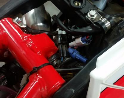
4 Diagnoses Relay (2015 X Trainer only) Oil pump location Figure 1 (X Trainer) Figure 2 ( RR ) Once the seat has been removed, remove the relay from the support and check that the resistance (pins 85 and 86) is approximately 80 Ohm. Check pin 30 and pin 87a for continuity. Power the relay coil (pins 85 and 86) with 12V on one terminal and ground on the other. Check pins 30 and 87a are in open circuit and pins 30 and 87 have continuity. *The X Trainer oil pump can be tested through the air box (Figure 1) but the RR pump can easily be tested by removing the battery strap from the battery and moving the battery and strap out of the way (Figure 2). Test the oil pump by removing the wiring plug and checking the resistance between the 2 terminals, 19.5ohms is the correct value, replace the oil pump if you get a reading greatly different then this. 3


5 Oil pump volume test Diagnosis Relay plug (2015 X Trainer only) Oil pump control unit (2105 X TRAINER ONLY) Step 1 Step 2 Step 3 *Warning light flashing or suspected incorrect oil amount. Oil flow verification: Empty the fuel tank then refill with 60:1 premix. Carefully disconnect the oil tube from the intake manifold and slide a piece of carb vent tubing over the end. Cap off the inlet jet. Start the bike and check the amount of oil flowing into the lengthened tubing. At idle there should be about 1 of oil flow in 90 seconds and 1 in 60 seconds revving or holding a higher RPM. If no oil is pumping, replace the Oil pump control unit 2015 x trainer only and the oil pump on all other bikes. *If you have oil flow and flashing warning light, proceed to step 2 on 2015 X trainer only. Test for voltage, one lead on the Pink-Black wire of the relay and the other lead to ground. Start the bike and after 15 seconds, Check that there is 12v. If you see a different voltage, replace the oil pump control unit. *See step 3 for oil control pump unit replacement. The oil pump control unit is located under the left side air box panel. The removal of the seat, air box cover and rear fender are necessary for replacement. *Once the unit has been replaced, test for normal oil flow and if it is corrected, drain the premix out of the tank and refill with standard fuel. 4
 Fig 1 Fig 2 TPS connector (RR location) Check the")


6 Regulator (same location on all bikes) TPS connector (Figures 1-3) (x Trainer location) Fig 1 Fig 2 TPS connector (RR location) Check the voltage between the battery terminals with the bike running and with a fully charged battery, if the voltage is less then 13.5v, replace the voltage regulator. Remove the fuel tank and unplug the TPS connector. Verify a resistance of 4.6 kohm between the Blue wire and the Black wire. With throttle closed, the resistance between the Yellow wire and the Black wire at 0% throttle should be 0,6 kohm and 3,2Kohm at 100% throttle. Fig 3 5


 of the primary")
 and the spark")

7 CDI/ECU (x trainer location) The CDI is located behind the air box cover, unplug the connector and check for damaged or oxidized pins and also look for damage to the harness. If everything checks out ok, proceed to the coil test on this same page. Coil Check that the resistance between tab (A) of the primary circuit and tab (B) is 0.6O Ohms +-20%. Check that the resistance between the same tab (B) and the spark plug wire end with the cap removed (C) is % The resistance measured between the ends of the cap should be 5.KOhms. *Replace the coil or cap if you find them to be out of spec. CDI/ECU (RR location) (RR location) (x trainer location) 6


")
8 Stator Pick up Wire colors Values Wire colors Values (RR location) (XT location) 7
9 2015 X Trainer only 8
10 2015 X Trainer electrical diagram legend only 9
11 2016 X Trainer only 10
12 2016 X Trainer electrical wiring diagram legend only 11
13 2017 X Trainer only 12
14 2017 X Trainer electrical wiring diagram legend only 13
15 2016 RR 2T wiring diagram only 14
16 2016 RR 2T wiring diagram legend only 15

17 2017RR 2T wiring diagram only 16
18 2017 RR 2Twiring diagram legend only 17
2T MY and X Trainer MY oil injection and Electrical trouble shooting guide
 2T MY 2016-18 and X Trainer MY 2015-18 oil injection and Electrical trouble shooting guide General information 1. Before performing the following diagnostic procedures, check wiring plugs and terminals
F - BASIC TESTING Infiniti G20 INTRODUCTION PRELIMINARY INSPECTION & ADJUSTMENTS VISUAL INSPECTION MECHANICAL INSPECTION
 F - BASIC TESTING 1992 Infiniti G20 1992 ENGINE PERFORMANCE Infiniti Basic Diagnostic Procedures G20, M30, Q45 INTRODUCTION The following diagnostic steps will help prevent overlooking a simple problem.
F - BASIC TESTING Nissan 240SX INTRODUCTION VISUAL INSPECTION COMPRESSION CHECK EXHAUST SYSTEM BACKPRESSURE CHECK
 F - BASIC TESTING 1990 Nissan 240SX 1990 ENGINE PERFORMANCE Nissan - Basic Diagnostic Procedures Nissan; Axxess, Maxima, Pathfinder, Pickup, Pulsar NX, Sentra, Stanza, Van, 240SX, 300ZX INTRODUCTION The
F - BASIC TESTING Toyota Celica INTRODUCTION PRELIMINARY INSPECTION & ADJUSTMENTS VISUAL INSPECTION MECHANICAL INSPECTION
 F - BASIC TESTING 1994 Toyota Celica 1994 ENGINE PERFORMANCE Toyota 4-Cylinder Basic Diagnostic Procedures Celica INTRODUCTION The following diagnostic steps will help prevent overlooking a simple problem.
F - BASIC TESTING Article Text 1992 Dodge Colt For a a a a a Copyright 1998 Mitchell Repair Information Company, LLC Saturday, April 27, :48PM
 Article Text ARTICLE BEGINNING 1992 ENGINE PERFORMANCE Chrysler Motors/Mitsubishi Basic Diagnostic Procedures Chrysler Motors: Colt, Colt 200, Summit Mitsubishi: Mirage INTRODUCTION The following diagnostic
4.0L CEC SYSTEM Jeep Cherokee DESCRIPTION OPERATION FUEL CONTROL DATA SENSORS & SWITCHES
 4.0L CEC SYSTEM 1988 Jeep Cherokee 1988 COMPUTERIZED ENGINE Controls ENGINE CONTROL SYSTEM JEEP 4.0L MPFI 6-CYLINDER Cherokee, Comanche & Wagoneer DESCRIPTION The 4.0L engine control system controls engine
2002 ENGINE PERFORMANCE. Self-Diagnostics - RAV4. Before performing testing procedures, check for any related Technical Service Bulletins (TSBs).
.") 2002 ENGINE PERFORMANCE Self-Diagnostics - RAV4 INTRODUCTION NOTE: Before performing testing procedures, check for any related Technical Service Bulletins (TSBs). To properly diagnosis and repair this
2002 ENGINE PERFORMANCE Self-Diagnostics - RAV4 INTRODUCTION NOTE: Before performing testing procedures, check for any related Technical Service Bulletins (TSBs). To properly diagnosis and repair this
1 of 14 9/4/2016 4:05 PM
 1 of 14 9/4/2016 4:05 PM P0068-MANIFOLD PRESSURE/THROTTLE POSITION CORRELATION P0068-Manifold Pressure/Throttle Position Correlation Theory of Operation This DTC sets when an unexpected high intake manifold
Fuel Injection System
 7. Fuel Injection System XCITING 400i Fuel Injection System This chapter covers the location and servicing of the fuel system components for the KYMCO XCITING 400i. Air box... 7-2~7-5 Fuel Tank... 7-6~7-10
Intake Manifold Tuning (IMT)
") Page 1 of 11 24-154 Intake Manifold Tuning (IMT) system Notes: The change-over of the manifold from long to short intake path occurs at approx. 4500 RPM. Component location page 24-1 Required special tools
Page 1 of 11 24-154 Intake Manifold Tuning (IMT) system Notes: The change-over of the manifold from long to short intake path occurs at approx. 4500 RPM. Component location page 24-1 Required special tools
F - BASIC TESTING Volvo 850 INTRODUCTION PRELIMINARY INSPECTION & ADJUSTMENTS VISUAL INSPECTION MECHANICAL INSPECTION
 F - BASIC TESTING 1995 Volvo 850 1995 ENGINE PERFORMANCE Volvo - Basic Diagnostic Procedures 850 INTRODUCTION NOTE: In this article, Engine Control Module (ECM) may also be referred to as Engine Control
Engine Cranks But Does Not Run
 Page 1 of 5 2000 GMC Truck GMC K Sierra - 4WD Sierra, Silverado, Suburban, Tahoe, Yukon (VIN C/K) Service Manual Engine Engine Controls - 4.8L, 5.3L, and 6.0L Diagnostic Information and Procedures Engine
ENGINE COOLING GROUP CONTENTS GENERAL INFORMATION SERVICE SPECIFICATIONS COOLANT SEALANT THERMOSTAT...
 14-1 GROUP 14 CONTENTS GENERAL INFORMATION 14-2 SERVICE SPECIFICATIONS 14-2 COOLANT 14-3 SEALANT 14-3 DIAGNOSIS 14-3 INTRODUCTION 14-3 TROUBLESHOOTING STRATEGY 14-3 SYMPTOM CHART 14-3 SYMPTOM PROCEDURES
Before performing spark test, ensure ignitor is properly grounded.
 Page 1 of 10 IGNITION CHECKS SPARK TEST NOTE: Before performing spark test, ensure ignitor is properly grounded. 1. Disconnect high tension coil wire from distributor. Hold coil wire approximately 1/2"
w.get2itparts.com Viper 90R-4 Dies After Shifting Or Indicator Lights Blink SCL /24/2005
 10/24/2005 Viper 90R-4 Dies After Shifting Or Indicator Problem: Unit will not shift into gear or engine dies when shifting into gear. (1) i. Turn on the ignition switch. ii. Set selector switch to neutral
ENGINE COOLING GROUP CONTENTS GENERAL INFORMATION SERVICE SPECIFICATIONS COOLANT SEALANT THERMOSTAT...
 14-1 GROUP 14 CONTENTS GENERAL INFORMATION 14-2 SERVICE SPECIFICATIONS 14-2 COOLANT 14-3 SEALANT 14-3 DIAGNOSIS 14-3 INTRODUCTION 14-3 TROUBLESHOOTING STRATEGY 14-3 SYMPTOM CHART 14-3 SYMPTOM PROCEDURES
FUEL INJECTION SYSTEM - MULTI-POINT
 FUEL INJECTION SYSTEM - MULTI-POINT 1988 Jeep Cherokee 1988 Electronic Fuel Injection JEEP MULTI-POINT 4.0L Cherokee, Comanche, Wagoneer DESCRIPTION The Multi-Point Electronic Fuel Injection (EFI) system
H - TESTS W/O CODES Volvo 960 INTRODUCTION SYMPTOMS SYMPTOM DIAGNOSIS ENGINE PERFORMANCE Volvo Trouble Shooting - No Codes
 H - TESTS W/O CODES 1994 Volvo 960 1994 ENGINE PERFORMANCE Volvo Trouble Shooting - No Codes Volvo; 850, 940, 960 INTRODUCTION Before diagnosing symptoms or intermittent faults, perform steps in appropriate
The installation instructions for an intake manifold flap control motor (Inlet Port Shut Off Valve) testing device of Mercedes Benz OM642 engine
 testing device of Mercedes Benz OM642 engine") The installation instructions for an intake manifold flap control motor (Inlet Port Shut Off Valve) testing device of Mercedes Benz OM642 engine 1. A brief description of the testing device. The testing
The installation instructions for an intake manifold flap control motor (Inlet Port Shut Off Valve) testing device of Mercedes Benz OM642 engine 1. A brief description of the testing device. The testing
Idle Air Control (IAC) System Diagnosis
 System Diagnosis") Page 1 of 6 2002 Chevrolet Tahoe - 4WD Avalanche, Escalade, Suburban, Tahoe, Yukon VIN C/K Service Manual Engine Engine Controls - 4.8L, 5.3L, and 6.0L Diagnostic Information and Procedures Document ID:
Page 1 of 6 2002 Chevrolet Tahoe - 4WD Avalanche, Escalade, Suburban, Tahoe, Yukon VIN C/K Service Manual Engine Engine Controls - 4.8L, 5.3L, and 6.0L Diagnostic Information and Procedures Document ID:
H - TESTS W/O CODES INTRODUCTION SYMPTOMS
 H - TESTS W/O CODES 1995 Volvo 850 1995 ENGINE PERFORMANCE Volvo - Trouble Shooting - No Codes 850 INTRODUCTION Before diagnosing symptoms or intermittent faults, perform steps in the F - BASIC TESTING
HIRTH 2703 Carburated - 55 hp
 HIRTH 2703 Carburated - 55 hp The 2703 V is an air cooled, piston controlled 2-cylinder-inline-2-stroke engine with one or two carburetors and Nikasil coated cylinders. It has one of the highest power
General Service Information
 KYMCO MXU 500i/700i Repair Manual Fuel System MXU 700i 3.Fuel System MXU 700i This chapter covers the location and servicing of the fuel system components for the fuel injected KYMCO MXU 700i models. 1.Airbox...
ELECTRONIC FUEL INJECTION
 Table of Contents ELECTRONIC FUEL INJECTION Section 3B - Troubleshooting and Diagnostics TROUBLESHOOTING AND DIAGNOSTICS Specifications........................... 3B-1 Special Tools...........................
Idle Air Control (IAC) System Diagnosis
 System Diagnosis") 2001 Oldsmobile Alero Idle Air Control (IAC) System Diagnosis Circuit Description The idle air control (IAC) valve is located in the throttle body. It consists of a movable pintle, driven by a gear attached
2001 Oldsmobile Alero Idle Air Control (IAC) System Diagnosis Circuit Description The idle air control (IAC) valve is located in the throttle body. It consists of a movable pintle, driven by a gear attached
HOWELL INSTALLATION MANUAL. Tuned Port Or LT-1 Fuel Injection Harness ( )
") HOWELL ENGINE DEVELOPMENTS, INC. FUEL INJECTION APPLICATIONS INSTALLATION MANUAL Tuned Port Or LT-1 Fuel Injection Harness (1985-1992) Howell Engine Developments, Inc. 6201 Industrial Way Marine City,
HOWELL ENGINE DEVELOPMENTS, INC. FUEL INJECTION APPLICATIONS INSTALLATION MANUAL Tuned Port Or LT-1 Fuel Injection Harness (1985-1992) Howell Engine Developments, Inc. 6201 Industrial Way Marine City,
Electronic Jet Kit Instructions
 Ver. 1.01 KFX 450 TFI-6040ST Thank you for choosing the Techlusion Electronic Jet Kit for your KFX 450, the TFI. The TFI is usable only for the following models: Kawasaki KFX 450 Thank you for choosing
TROUBLE SHOOTING > SYMPTOM DIAGNOSIS > SOME OR ALL SHIFTS MISSING TROUBLE SHOOTING > SYMPTOM DIAGNOSIS > NO 1-2, 2-3 OR 3-4 UPSHIFT (AUTOMATIC)
") AUTOMATIC TRANSMISSION - DIAGNOSIS - E4OD A/T TROUBLE SHOOTING 1997 Ford Pickup 7.3L Eng F350 Question: overdrive off light is on steady TROUBLE SHOOTING > SYMPTOM DIAGNOSIS Question: Repeat OD planetary
AUTOMATIC TRANSMISSION - DIAGNOSIS - E4OD A/T TROUBLE SHOOTING 1997 Ford Pickup 7.3L Eng F350 Question: overdrive off light is on steady TROUBLE SHOOTING > SYMPTOM DIAGNOSIS Question: Repeat OD planetary
Computers and Control Systems: Symptom Related Diagnostic Procedures C Charts. Part 1 of 6. Chart C-1 (1 Of 6)
") 1993 Cadillac DeVille V8-300 4.9L Page 1 Computers and Control Systems: Symptom Related Diagnostic Procedures C Charts Part 1 of 6 Chart C-1 (1 Of 6) 1993 Cadillac DeVille V8-300 4.9L Page 2 Wiring Diagram.
1993 Cadillac DeVille V8-300 4.9L Page 1 Computers and Control Systems: Symptom Related Diagnostic Procedures C Charts Part 1 of 6 Chart C-1 (1 Of 6) 1993 Cadillac DeVille V8-300 4.9L Page 2 Wiring Diagram.
Counter-clockwise, view to output shaft Mixture 1:50, 2-stroke-oil, fuel min. 95 octane (RON)
") HIRTH 2703 Carburated - 55 hp The 2703 V is an air cooled, piston controlled 2-cylinder-inline-2-stroke engine with one or two carburetors and Nikasil coated cylinders. It has one of the highest power
HIRTH 2703 Carburated - 55 hp The 2703 V is an air cooled, piston controlled 2-cylinder-inline-2-stroke engine with one or two carburetors and Nikasil coated cylinders. It has one of the highest power
SELF-DIAGNOSTIC TESTS
 Page 1 of 10 1997 Chrysler Sebring 2.5L Eng JX SELF-DIAGNOSTIC TESTS NOTE: When using diagnostic tests, DO NOT skip any steps or incorrect diagnosis may result. Ensure battery is fully charged. in appropriate
RETRIEVING DIAGNOSTIC TROUBLE CODES
 Page 1 of 13 SELF-DIAGNOSTICS A/C-heater control assembly monitors system circuits and stores a code in memory if a problem is detected. All codes are stored in memory except Code 2 Malfunction is current
SERVICE BULLETIN REFERENCES 1983
 J a I) SERVICE BULLETIN REFERENCES 1983 19.35 TROUBLE SHOOTING Engine Won t Start or Hard Starting Possible Cause ALL MODELS No fuel in tank. Fuel valve off. Insufficient or excessive priming. Spark plug
F - BASIC TESTING Subaru SVX INTRODUCTION PRELIMINARY INSPECTION & ADJUSTMENTS VISUAL INSPECTION MECHANICAL INSPECTION
 F - BASIC TESTING 1992 Subaru SVX 1992 ENGINE PERFORMANCE Subaru Basic Diagnostic Procedures SVX INTRODUCTION The following diagnostic steps help prevent overlooking a simple problem. This is also where
Viper 90R Dies After Shifting
 3/9/2005 Problem: Unit will not shift into gear or engine dies when shifting into gear. (1) i. Turn on the ignition switch. ii. Set selector switch to neutral (N) position. iii. Set stop switch to O position.
 Troubleshooting flowcharts CONTACT US 1-877-838-1399 support@rmstator.com Local & International: 819-849-7333 www.rmstator.com MELTED CONNECTORS CIRCLE OF DEATH Mispositioned connectors create irregular
3.4L V6 SUPERCHARGER 7 TH INJECTOR KIT
 Part Number: 00602-17620-260 00602-17620-261 00602-17620-263 00602-17620-264 00602-17620-274 00602-17620-275 00602-17620-276 Section I Installation Preparation Kit Contents Item # Quantity Reqd. Description
2005 Hyundai Truck Santa Fe V6-3.5L
 2005 Hyundai Truck Santa Fe V6-5L Vehicle» A L L Diagnostic Trouble Codes ( DTC )» Testing and Inspection» P Code Charts» P0320 DTC P0320 IGNITION/DISTRIBUTOR ENGINE SPEED INPUT CIRCUIT Component Location
ENGINE AND EMISSION CONTROL
 17-1 ENGINE AND EMISSION CONTROL CONTENTS EMISSION CONTROL SYSTEM... 2 GENERAL... 2 Outline of Changes... 2 GENERAL INFORMATION... 2 SERVICE SPECIFICATION... 2 VACUUM HOSE... 3 Vacuum Hose Piping Diagram...
DTC P1415 Secondary Air Injection (AIR) System Bank 1
 System Bank 1") Page 1 of 5 2000 GMC Truck GMC K Sierra - 4WD Sierra, Silverado, Suburban, Tahoe, Yukon (VIN C/K) Service Manual Document ID: 546887 DTC P1415 Secondary Air Injection (AIR) System Bank 1 Circuit Description
Page 1 of 5 2000 GMC Truck GMC K Sierra - 4WD Sierra, Silverado, Suburban, Tahoe, Yukon (VIN C/K) Service Manual Document ID: 546887 DTC P1415 Secondary Air Injection (AIR) System Bank 1 Circuit Description
PRELIMINARY INSPECTION & ADJUSTMENTS
 PRELIMINARY INSPECTION & ADJUSTMENTS VISUAL INSPECTION Most driveability problems in the engine control system result from faulty wiring, poor electrical connections or leaking air and vacuum hose connections.
DIAGNOSIS AND TESTING
 412-00-1 Climate Control System - General Information 412-00-1 DIAGNOSIS AND TESTING Climate Control System Refer to Wiring Diagrams Cell 54, Air Conditioning/Heater for schematic and connector information.
TEST CHART. Voltage Supply
 ALL MEASUREMENTS ARE MADE ON THE TERMINALS OF THE DISCONNECTED WIRING HARNESS PLUG TO THE CONTROL UNIT (ECU) WITH IGNITION OFF UNLESS OTHERWISE INDICATED. Voltage Supply Ignition Voltage supply to the
1 GENERAL INFORMATION,
 CONTENTS 1 GENERAL INFORMATION, AND BOATING SAFETY HOW TO USE THIS MANUAL 1 2 BOATING SAFETY 1 3 SAFETY IN SERVICE 1-11 TOOLS AND EQUIPMENT 2-2 TOOLS 2-4 FASTENERS, MEASUREMENTS AND CONVERSIONS 2-12 ENGINE
WEBER CARBURETOR TROUBLESHOOTING GUIDE
 This guide is to help pinpoint problems by diagnosing engine symptoms associated with specific vehicle operating conditions. The chart will guide you step by step to help correct these problems. For successful
INSTALLATION OVERVIEW: Connector, 7-pin. Clips w/plastic Ties. Plastic Ties. Connector, 52-pin. Step 22 a) Step 21 a) Step 23. Step 24.
 Step 21 a) Step 23. Step 24.") GENUINE PARTS INSTALLATION INSTRUCTIONS DESCRIPTION: APPLICATION: PART NUMBER: KIT CONTENTS: Tow Hitch Wire Harness Kit NV Cargo & Passenger 999T8 HW000 Installation of this accessory requires installation
GENUINE PARTS INSTALLATION INSTRUCTIONS DESCRIPTION: APPLICATION: PART NUMBER: KIT CONTENTS: Tow Hitch Wire Harness Kit NV Cargo & Passenger 999T8 HW000 Installation of this accessory requires installation
Document ID# Chevrolet Corvette
 Page 1 of 6 Document ID# 610892 2000 Chevrolet Corvette Feedback Print D T C P 0 4 6 2 F u e l L e v e l S e n s o r C i r c u i t L o w V o l t a g e C i r c u i t D e s c r i p t i
ALTERNATOR REQUESTED INFORMATION. Vehicles With Dual Generator [ Engine Mount - LH ] 2007 Ford Pickup 6.0L Eng F350 Super Duty
![ALTERNATOR REQUESTED INFORMATION. Vehicles With Dual Generator [ Engine Mount - LH ] 2007 Ford Pickup 6.0L Eng F350 Super Duty](/thumbs/72/66590437.jpg "ALTERNATOR REQUESTED INFORMATION. Vehicles With Dual Generator [ Engine Mount - LH ] 2007 Ford Pickup 6.0L Eng F350 Super Duty") ALTERNATOR 2007 Ford Pickup 6.0L Eng F350 Super Duty REQUESTED INFORMATION Vehicles With Dual Generator [ Engine Mount - LH ] Fig 1: Rotating Drive Belt Tensioner Clockwise 1. Remove the accessory drive
ALTERNATOR 2007 Ford Pickup 6.0L Eng F350 Super Duty REQUESTED INFORMATION Vehicles With Dual Generator [ Engine Mount - LH ] Fig 1: Rotating Drive Belt Tensioner Clockwise 1. Remove the accessory drive
Innovative Racing Electronics
 MPS Fast FI Mixture Control Installation Instructions The MPS Fast FI Mixture Control P/N 1-0337 is a simple means to adjust the fuel curves on your fuel-injected motorcycle. This allows for tuning after
1998 ENGINE PERFORMANCE. General Motors Corp. - Basic Diagnostic Procedures - 5.7L
 INTRODUCTION 1998 ENGINE PERFORMANCE General Motors Corp. - Basic Diagnostic Procedures - 5.7L The following diagnostic steps will help prevent overlooking a simple problem. This is also where to begin
FUEL SYSTEM DIAGNOSIS - HIGH PRESSURE SIDE
 2003 Chevy Truck C 2500 Truck 2WD V8-6.6L DSL Turbo VIN 1 Vehicle > Powertrain Management > Computers and Control Systems > Testing and Inspection > Component Tests and General Diagnostics FUEL SYSTEM
Service Manual. Extractor Model XR28QP. For The. For: Troubleshooting Adjustments
 Service Manual For The X Ride 28 Rider Extractor Model XR28QP For: Training Troubleshooting Adjustments Contents 1 Cautions ------------------------------------------------------------------------------
DIAGNOSIS AND TESTING
 412-00-1 Climate Control System - General Information 412-00-1 DIAGNOSIS AND TESTING Climate Control System Refer to Wiring Diagrams Cell 54, Air Conditioner/Heater for schematic and connector information.
HIRTH ENGINE SETTING VALUES. 55 HP Engine Fan cooled engine
 HIRTH ENGINE SETTING VALUES 55 HP Engine Fan cooled engine Engine 55HP FC Ign. Timing @ 2000 Carbureted 14 BTC Spark Plug Heat VI * 280 Spark Plug Gap.020-.024 No. of Carburetors Two Carburetor ID # Bing
 TRACTION CONTROL SYSTEM 1996 Toyota Supra 1995-96 BRAKES Traction Control Supra DESCRIPTION Toyota Traction Control (TRAC) system controls engine torque and braking of the driving wheels. TRAC system is
5 Volt Sensor Supply Circuit - Test
 Page 1 of 10 Shutdown SIS Previous Screen Product: INDUSTRIAL ENGINE Model: C4.4 INDUSTRIAL ENGINE 444 Configuration: C4.4 Industrial Engine 44400001-UP Troubleshooting C4.4 and C6.6 Industrial Engines
G - TESTS W/CODES - 2.2L
 G - TESTS W/CODES - 2.2L 1994 Toyota Celica 1994 ENGINE PERFORMANCE Toyota 2.2L Self-Diagnostics Celica INTRODUCTION If no faults were found while performing F - BASIC TESTING, proceed with self-diagnostics.
1999 Toyota RAV ACCESSORIES & EQUIPMENT Cruise Control Systems - RAV4
 1999 ACCESSORIES & EQUIPMENT Cruise Control Systems - RAV4 DESCRIPTION WARNING: Deactivate air bag system before performing any service operation. See AIR BAG RESTRAINT SYSTEMS article. DO NOT apply electrical
On Board Diagnostics II PCED
 Page 1 of 5 1999 PCED On Board Diagnostics II SECTION 5: Pinpoint Tests HD: Misfire Detection Monitor HD: Introduction HD1 DTC P0301-P0310: CHECK FOR NO LOW FUEL te: Running out of fuel can turn on the
HIRTH 3203 Carburated - 65 hp
 HIRTH 3203 Carburated - 65 hp 2706-65Hp engine shown with fan cooling HIRTH s most popular engine. The 3203 produces more horsepower and torque per pound than any other engine in its power class. Hirth
Parking Brake Indicator Is Flashing
 Page 1 of 5 Troubleshooting 247B, 257B, 267B, 277B and 287B Multi Terrain Loaders and 216B, 226B, 232B, 236B, 242B, 246B, 248B, 252B, 262B and 268B Skid Steer Loaders Interlock Electronic Control System
 Page 1 of 34 Print Date: 1994 ENGINE PERFORMANCE FORD MOTOR CO. - SYSTEM & COMPONENT TESTING - EEC-IV 5.0L INTRODUCTION 1994 Ford Mustang 5.0L Eng VIN T GT Before testing separate components or systems,
Engine Cylinder Head Installation
 Engine Cylinder Head Installation Important: Install the cylinder head without the camshafts. 1. Install the engine cylinder head to the engine block. 2. Install the AIR pump bolt and fir tree fastener
HOW TO PROCEED WITH TROUBLESHOOTING
 2005 BRAKES Anti-Lock Brake System With Electronic Brake Force Distribution (EBD) - Diagnostics - RAV4 HOW TO PROCEED WITH TROUBLESHOOTING Troubleshoot in accordance with the following procedures. Fig.
Note: If DTCs P0670 and P0684 are present, carry out DTC P0670 diagnosis before diagnosing DTC P0684.
 2008 F-250 2008 PCED 6.4L Diesel SECTION 5: Pinpoint Tests Report a problem with this article Procedure revision date: 03/09/2010 AF: Glow Plug System AF: Introduction AF1 PRELIMINARY DIAGNOSIS te: If
1984 Jeep CJ7. IGNITION SYSTEM - SOLID STATE' 'Distributors & Ignition Systems MOTORCRAFT SOLID STATE IGNITION (SSI)
") TESTING SECONDARY CIRCUIT CHECK CAUTION: When checking secondary voltage, do not remove spark plug wires from spark plugs No. 3 on 4-cylinder, No. 1 or 5 on 6-cylinder and No. 3 or 4 on V8 Engines. 1.
TESTING SECONDARY CIRCUIT CHECK CAUTION: When checking secondary voltage, do not remove spark plug wires from spark plugs No. 3 on 4-cylinder, No. 1 or 5 on 6-cylinder and No. 3 or 4 on V8 Engines. 1.
 Page 1 of 10 Year = 2008 Model = F-150 Engine = VIN = IDS Version = t Available Variable Camshaft Timing (VCT) This pinpoint test is intended to diagnose the following: VCT solenoid (6L713) or (6B297)
ARTICLE BEGINNING INTRODUCTION SELF-DIAGNOSTIC SYSTEM RETRIEVING DTCS ENGINE PERFORMANCE Volkswagen Self-Diagnostics - Gasoline
 Article Text ARTICLE BEGINNING 1996 ENGINE PERFORMANCE Volkswagen Self-Diagnostics - Gasoline Cabrio, Golf III, GTI, Jetta III, Passat INTRODUCTION If no faults were found while performing preliminary
DTC P1431 Fuel Level Sensor 2 Performance
 Page 1 of 8 Document ID# 610929 2000 Chevrolet Corvette Feedback Print DTC P1431 Fuel Level Sensor 2 Performance Circuit Description The right fuel level sensor 2, mounted in the rear
A L L Diagnostic Trouble Codes ( DTC ): P Code Charts P161B DTC P161B ECM/PCM INTERNAL ERROR - TORQUE CALCULATION
: P Code Charts P161B DTC P161B ECM/PCM INTERNAL ERROR - TORQUE CALCULATION") 2006 Kia Truck Sedona V6-3.8L Copyright 2013, ALLDATA 10.52 Page 1 A L L Diagnostic Trouble Codes ( DTC ): P Code Charts P161B DTC P161B ECM/PCM INTERNAL ERROR - TORQUE CALCULATION ENERAL DESCRIPTION Component
2006 Kia Truck Sedona V6-3.8L Copyright 2013, ALLDATA 10.52 Page 1 A L L Diagnostic Trouble Codes ( DTC ): P Code Charts P161B DTC P161B ECM/PCM INTERNAL ERROR - TORQUE CALCULATION ENERAL DESCRIPTION Component
G - TESTS W/CODES Volvo 960 INTRODUCTION SELF-DIAGNOSTIC SYSTEM ENGINE PERFORMANCE Volvo Self-Diagnostics
 G - TESTS W/CODES 1994 Volvo 960 1994 ENGINE PERFORMANCE Volvo Self-Diagnostics 960 INTRODUCTION If no faults were found while performing BASIC DIAGNOSTIC PROCEDURES, proceed with SELF-DIAGNOSTIC SYSTEM.
7/2/2018 PPT DV: Throttle Body Assembly Electronic Throttle Control (ETC) - Gasoline Engines (Powertrain Diagnostics) 2014 Ford Escape Mot
 - Gasoline Engines (Powertrain Diagnostics) 2014 Ford Escape Mot") 2014 Escape 2015 PCED Gasoline Engines SECTION 5: Pinpoint Tests Report a problem with this article Procedure revision date: 07/30/2015 DV: Throttle Body Assembly Electronic Throttle Control (ETC) DV:
2014 Escape 2015 PCED Gasoline Engines SECTION 5: Pinpoint Tests Report a problem with this article Procedure revision date: 07/30/2015 DV: Throttle Body Assembly Electronic Throttle Control (ETC) DV:
BASIC DIAGNOSTIC PROCEDURES
 BASIC DIAGNOSTIC PROCEDURES 2001 Chevrolet Camaro 2001 ENGINE PERFORMANCE Basic Diagnostic Procedures - Cars Except Metro & Prizm MODEL IDENTIFICATION MODEL IDENTIFICATION Body Code (1) Model C... Park
ENGINE 01 02A 1. Toc of SCT ON-BOARD DIAGNOSTIC [ENGINE. Toc of SCT 01 02A ON-BOARD DIAGNOSTIC [ENGINE CONTROL SYSTEM (ZM)] 01 02A
![ENGINE 01 02A 1. Toc of SCT ON-BOARD DIAGNOSTIC [ENGINE. Toc of SCT 01 02A ON-BOARD DIAGNOSTIC [ENGINE CONTROL SYSTEM (ZM)] 01 02A](/thumbs/90/103285807.jpg "ENGINE 01 02A 1. Toc of SCT ON-BOARD DIAGNOSTIC [ENGINE. Toc of SCT 01 02A ON-BOARD DIAGNOSTIC [ENGINE CONTROL SYSTEM (ZM)] 01 02A") ENGINE 01 SECTION Toc of SCT ON-BOARD DIAGNOSTIC [ENGINE CONTROL SYSTEM (ZM)]...01-02A ON-BOARD DIAGNOSTIC [ENGINE CONTROL SYSTEM (FS)]...01-02B ON-BOARD DIAGNOSTIC [CRUISE CONTROL SYSTEM].......01-02C
ENGINE 01 SECTION Toc of SCT ON-BOARD DIAGNOSTIC [ENGINE CONTROL SYSTEM (ZM)]...01-02A ON-BOARD DIAGNOSTIC [ENGINE CONTROL SYSTEM (FS)]...01-02B ON-BOARD DIAGNOSTIC [CRUISE CONTROL SYSTEM].......01-02C
01 02B ON-BOARD DIAGNOSTIC [ENGINE CONTROL SYSTEM (FS)]
![01 02B ON-BOARD DIAGNOSTIC [ENGINE CONTROL SYSTEM (FS)]](/thumbs/80/80600627.jpg "01 02B ON-BOARD DIAGNOSTIC [ENGINE CONTROL SYSTEM (FS)]") ON-BOARD DIAGNOSTIC [ENGINE CONTROL SYSTEM (FS)] CONTROL SYSTEM WIRING DIAGRAM [FS]............................ 2 CONTROL SYSTEM DEVICE AND CONTROL RELATIONSHIP CHART [FS]........ 4 Engine Control System............
ON-BOARD DIAGNOSTIC [ENGINE CONTROL SYSTEM (FS)] CONTROL SYSTEM WIRING DIAGRAM [FS]............................ 2 CONTROL SYSTEM DEVICE AND CONTROL RELATIONSHIP CHART [FS]........ 4 Engine Control System............
VEHICLE SPEED CONTROL SYSTEM
 J VEHICLE SPEED CONTROL SYSTEM 8H - 1 VEHICLE SPEED CONTROL SYSTEM CONTENTS page DIAGNOSIS... 2 GENERAL INFORMATION... 1 page SERVICE PROCEDURES... 9 GENERAL INFORMATION The vehicle speed control system
DIAGNOSIS AND TESTING
 307-01-1 Automatic Transaxle/Transmission 307-01-1 DIAGNOSIS AND TESTING Special Testing Procedures Special Tool(s) Air Test Plate, Transmission 307-405 Transmission Fluid Pressure Gauge 307-004 (T57L-77820-A)
1993 ENGINE PERFORMANCE Volkswagen Basic Diagnostic Procedures. Cabriolet, Corrado SLC, EuroVan, Fox, Golf, GTI, Jetta, Passat GL, Passat GLX
 Article Text ARTICLE BEGINNING 1993 ENGINE PERFORMANCE Volkswagen Basic Diagnostic Procedures Cabriolet, Corrado SLC, EuroVan, Fox, Golf, GTI, Jetta, Passat GL, Passat GLX INTRODUCTION The following diagnostic
SECTION Climate Control System - General Information
 412-00-i Climate Control System - General Information 412-00-i SECTION 412-00 Climate Control System - General Information CONTENTS PAGE DIAGNOSIS AND TESTING Climate Control System... 412-00-2 Inspection
75/90 FOURSTROKE EFI WIRING DIAGRAM
 75/0 FOURSTROKE EFI WIRING DIAGRAM 0-87725 MARCH 2005 Page 8A-3 75/0 FourStroke EFI Wiring Diagram - Electronic control module (ECM) 2 - Engine water temperature sensor 3 - Ignition coil for cylinder #
Simple Carburettor Fuel System for a Piston Engine. And how it works
 Simple Carburettor Fuel System for a Piston Engine And how it works Inlet Exhaust Tank PISTON ENGINE Carburettor Fuel System Filler Cap COCKPIT FUEL GAUGE E FUEL 1/2 F Filler Neck Tank Cavity FUEL LEVEL
DTC P0102 Mass Air Flow (MAF) Sensor Circuit Low Frequency
 Sensor Circuit Low Frequency") Page 1 of 5 1997 Pontiac Grand Prix Grand Prix (VIN W) Service Manual Engine Engine Controls - 3.8L Diagnostic Information and Procedures Document ID: 106986 DTC P0102 Mass Air Flow (MAF) Sensor Circuit
Page 1 of 5 1997 Pontiac Grand Prix Grand Prix (VIN W) Service Manual Engine Engine Controls - 3.8L Diagnostic Information and Procedures Document ID: 106986 DTC P0102 Mass Air Flow (MAF) Sensor Circuit
1995 Ford Mustang ENGINE PERFORMANCE System/Component Tests - EEC-IV (5.0L)
") DISTRIBUTOR IGNITION SYSTEM Preliminary Check Perform following preliminary checks: Visually inspect engine compartment to verify vacuum hoses and spark plug wires are properly routed/securely connected.
DISTRIBUTOR IGNITION SYSTEM Preliminary Check Perform following preliminary checks: Visually inspect engine compartment to verify vacuum hoses and spark plug wires are properly routed/securely connected.
Thank you for choosing the Techlusion Electronic Jet Kit, the TFI. The TFI is usable for sequential fuel injection 2 cylinder Suzuki motorcycles **.
 Rev 1.1.1 2055ST TFI TFI Patent Numbers: 7,000,599 & 7,124,742 TFI Instructions Suzuki Thank you for choosing the Techlusion Electronic Jet Kit, the TFI. The TFI is usable for sequential fuel injection
SPN 51 or Suspect Parameter Number (SPN) and Failure Mode Indicator (FMI) Description
 and Failure Mode Indicator (FMI) Description") SPN 51 or 3673 Suspect Parameter Number (SPN) and Failure Mode Indicator (FMI) Description SPN FMI Description Possible Causes 51 3 TPS1 Sensor Signal Voltage High Open/high resistance in low Short to
SPN 51 or 3673 Suspect Parameter Number (SPN) and Failure Mode Indicator (FMI) Description SPN FMI Description Possible Causes 51 3 TPS1 Sensor Signal Voltage High Open/high resistance in low Short to
Error codes Diagnostic plug Read-out Reset Signal Error codes
 Error codes Diagnostic plug Diagnostic plug: 1 = Datalink LED tester (FEN) 3 = activation error codes (TEN) 4 = positive battery terminal (+B) 5 = ground Read-out -Connect LED tester to positive battery
SUZUKI SV
 SUZUKI SV650 2007-2011 Z-Fi Installation Instructions Part # F640 May result in the activation of the FI light (indicating injector fault) but does NOT cause actual running issues Parts List: Z-Fi Control
Intake air temperature sensor may be also identified using appropriate illustration in THEORY/OPERATION article.
 Page 1 of 5 ARTICLE BEGINNING INTRODUCTION Sensor operating range information can help determine if a sensor is out of calibration. An out-ofcalibration sensor may not set a trouble code, but it may cause
The following diagnostic steps will help prevent overlooking a simple problem. This is also where to begin diagnosis for a no-start condition.
 ENGINE CONTROLS - BASIC TESTING INTRODUCTION 1991 Cadillac Seville 4.9L Eng STS The following diagnostic steps will help prevent overlooking a simple problem. This is also where to begin diagnosis for
D - ADJUSTMENTS Nissan 240SX ENGINE COMPRESSION VALVE CLEARANCE IGNITION TIMING ENGINE PERFORMANCE On-Vehicle Adjustments
 D - ADJUSTMENTS 1990 Nissan 240SX 1990 ENGINE PERFORMANCE On-Vehicle Adjustments Nissan; Axxess, Stanza, 240SX ENGINE COMPRESSION 1) Start engine and warm to normal operating temperature. Disconnect distributor
AUTOMATIC AIR CONDITIONER > COMPONENT DIAGNOSIS > BLOWER MOTOR CONTROL SYSTEM > SYSTEM DESCRIPTION > SYSTEM DESCRIPTION
 2008 Nissan Armada 5.6L Eng SE HEATER & AIR CONDITIONING CONTROL SYSTEM MOTOR CONTROL SYSTEM > SYSTEM DESCRIPTION > SYSTEM DESCRIPTION Component Parts Blower speed control system components are: A/C auto
REMOVAL. Fig Sized for Print
 ALLDATA Online - 2000 Dodge Truck Grand Caravan FWD V6-3.3L VIN R - Intake M... Page 1 of 10 REMOVAL 1. Remove windshield wiper module. 2. Perform fuel system pressure release procedure (before attempting
DIAGNOSIS AND TESTING
 206-09-1 Vehicle Dynamic Systems 206-09-1 DIAGNOSIS AND TESTING Anti-Lock Control Traction Control and Stability Assist Special Tool(s) Principles of Operation 73III Automotive Meter 105-R0057 or equivalent
255 Liter/Hr, In Tank Fuel Pump For Chrysler Front Wheel Drive Vehicles Catalog # INSTALLATION INSTRUCTIONS
 255 Liter/Hr, In Tank Fuel Pump For 1984-1990 Chrysler Front Wheel Drive Vehicles Catalog # 17934 INSTALLATION INSTRUCTIONS PLEASE study these instructions carefully before installing your new In-Tank
Propane and Gasoline Electronic Fuel Injection
 Zenith Electronic Engine Management System Propane and Gasoline Electronic Fuel Injection 1 Slide 1 2 Slide 2 Home Page System Advantages Block Diagram, Electronic Control Unit Inputs Output Controls System
On all settings above 100 horsepower the following precautions should be observed:
 ELECTRONIC FUEL INJECTED 5.0 COYOTE PLATE SYSTEM INSTALLATION INSTRUCTIONS Congratulations on the purchase of your Nitrous Express Coyote Plate system. Nitrous Express utilizes only the highest quality
 Page 1 of 54 412-00 Climate Control System General Information and Diagnostics 2006 Crown Victoria/Grand Marquis DIAGNOSIS AND TESTING Procedure revision date: 12/23/2008 Climate Control System Printable
Honda Accord/Prelude
 Honda Accord/Prelude 1984-1995 In Tank Fuel Pumps TEST 1. Turn the ignition OFF. 2. On the Accord, remove the screws securing the underdash fuse box to its mount. Remove the fuel cut off relay from the
1994 ENGINE PERFORMANCE TOYOTA SYSTEM & COMPONENT TESTING
 1 of 65 12/5/2014 1:13 PM 1994 ENGINE PERFORMANCE TOYOTA SYSTEM & COMPONENT TESTING INTRODUCTION Before testing separate components or systems, perform procedures in articles listed below: BASIC TESTING
Counter-clockwise, view to output shaft Mixture 1:50, 2-stroke-oil, fuel min. 95 octane (RON)
") HIRTH 2703 Carburated - 55 hp The 2703 V is an air cooled, piston controlled 2-cylinder-inline-2-stroke engine with one or two carburetors and Nikasil coated cylinders. It has one of the highest power
HIRTH 2703 Carburated - 55 hp The 2703 V is an air cooled, piston controlled 2-cylinder-inline-2-stroke engine with one or two carburetors and Nikasil coated cylinders. It has one of the highest power