PF SERIES PUMPS PFS ATEX VERSION (INCLUDES M6A, M6XA, M10X MOTORS & SPK) OPERATION & PARTS MANUAL
|
|
|
- Mervin Holland
- 6 years ago
- Views:
Transcription


1 PF SERIES PUMPS PFS ATEX VERSION (INCLUDES M6A, M6XA, M10X MOTORS & SPK) OPERATION & PARTS MANUAL
2 Introduction This manual pertains to the PF Series, specifically the ATEX version of the PFS stainless steel drum pump. Finish Thompson Inc. thanks you for choosing our products. We believe the use of our products will be fully satisfactory. When properly installed and operated, your Finish Thompson motor and pump will provide long, trouble-free service; therefore, please read this manual carefully before carrying out any operations on the pump/motor unit. Any use other than that described herein is considered incorrect; and, consequently, Finish Thompson Inc. shall not be held responsible for any damages to people or property. In case of doubt or enquiries, please reply to our Technical Service department directly at the following address: Finish Thompson, Inc. 921 Greengarden Rd. Erie, PA U.S.A. Tel ; Fax Index Introduction... 1 Warranty, General Terms & Conditions... 2 Safety... 3 Pump Specifications... 4 ATEX Specifications... 5 PFS Installation... 6 Static Protection Kit Assembly Maintenance Disassembly... 7 Inspection... 8 Reassembly... 8 Exploded View... 9 Pump Tube Spare Parts List M6A Spare Parts LIst & View M6XA Spare Parts List & View M10X Spare Parts LIst & View ATEX Certificates EC Certificates of Conformity Technical Service Hotlne: or techservice@finishthompson.com 1
3 Warranty, General Terms & Conditions 1. The following terms and conditions apply to the sale of machinery, components and related services and products, of Finish Thompson Inc. (hereinafter the products ) 2. Finish Thompson Inc. (the manufacturer) warrants only that: a) its products are free of defects in material, design and workmanship at the time of original purchase; b) its products will function in accordance with Finish Thompson Inc. operation manuals; Finish Thompson Inc. does not guarantee that the product will meet the precise needs of the Customer, except for those purposes set out in any invitation to render documents or other documents specifically made available to Finish Thompson Inc. before entering into this agreement; c) high quality materials are used in the construction of the pumps and that machining and assembly are carried out to the highest standards. Except as expressly stated above, Finish Thompson Inc. makes no warranties, express or implied, concerning the products, including all warranties of fitness for a particular purpose. This warranty shall not be applicable in circumstances other than defects in material, design, and workmanship. In particular warranty shall not cover the following: d) Periodic checks, maintenance, repair and replacement of parts due to normal wear and tear; e) Damage to the product resulting from: i. Tampering with, abuse or misuse, including but not limited to failure to use the product for its normal purposes as stated at the time of purchase or in accordance with Finish Thompson, Inc. instructions for use and maintenance of the product, or the installation or improper ventilation or use of the product in a manner inconsistent with the technical or ii. safety standard in force; Repairs performed by non-authorized service workshop, or opening of the unit by non-authorized personnel, or use of non genuine Finish Thompson Inc. parts; iii. Accidents, force majeure or any cause beyond the control of Finish Thompson Inc., including but not limited to lightning, water, fire, earthquake, and public disturbances, etc. 3. The warranty shall cover the replacement or repair of any part, which is documented to be faulty due to construction or assembling, with new or repaired parts free of charge delivered by Finish Thompson, Inc. Parts subjected to normal wear and tear shall not be covered by the warranty. Finish Thompson, Inc. shall decide as to whether the defective or faulty part shall be replaced or repaired. Transportation charges are prepaid to Finish Thompson. 4. The warranty of the products shall be valid for a period of 12 months from the date of delivery, under the condition that notice of the alleged defect to the products or parts thereof be given to Finish Thompson, Inc. within the term of 8 days from the discovery. 5. Repair or replacement under the terms of this warranty shall not give a right to an extension to, or a new commencement of, the period of warranty. Repair or replacement under the terms of this warranty may be fulfilled with functionally equivalent reconditioned units. Finish Thompson Inc. qualified personnel shall be solely entitled to carry out repair or replacement of faulty parts after careful examination of the motor. Faulty parts or components when replaced by Finish Thompson Inc. will become the property of Finish Thompson Inc. If this warranty does not apply, the purchaser shall bear all cost for labor, material and transportation. 6. Finish Thompson Inc. will not be liable on any claim, whether in contact, tort, or otherwise, for any indirect, special, incidental, or consequential damages, caused to the customer or to third parties, including loss of profits, process down time, transportation costs, costs associated with replacement or substitution products, labor costs, installation or removal costs. In any and all events, manufacturer s liability shall not exceed the purchase price of the product and/or accessories. 7. Return Policy. Should you have any problems with this product, please contact the distributor in your area. The distributor will determine if a return to the factory is necessary and will contact the factory for a Return Authorization Number. Otherwise, contact our Technical Service Hotline ( ) or techservice@finishthompson.com if you have any questions regarding product operation or repair. 2
4 Safety 1. Introduction This manual contains all the information needed for the correct installation, use and maintenance of your new Finish Thompson pump. It should be read and understood by all the personnel involved in installation, operating and servicing of the pump before it is started. 2. Operator Qualification and Training The personnel in charge of the installation, the operation, and the maintenance of the pump must be qualified and able to perform the operations described in this manual. Finish Thompson, Inc. shall not be held responsible for the training level of personnel and for the fact that they are not fully aware of the contents of this manual. 3. Safety Instructions FOR YOUR OWN SAFETY BEFORE using or servicing your pump, please make sure to wear the proper clothing, eye protection and follow standard safety procedures when handling corrosive or personally harmful materials. GENERAL DANGER ALWAYS use a stainless steel pump tube with an explosion proof electric motor or air motor and static protection kit with grounded discharge hose when pumping or mixing flammable or combustible material. ALWAYS use and store the pump and motor in an upright position. NEVER use in pressurized containers. ALWAYS use a chemically compatible hose rated for the temperature of the product being pumped. ALWAYS select the proper o-ring material. Improper material selection could lead to swelling and be a possible source of leaks. This is the responsibility of the end user. ALWAYS check the pump for leaks on a regular basis. If leaks are noticed, the pump must be repaired or replaced immediately. ALWAYS clean the pump on a regular basis to avoid any dust buildup greater than 5mm deep. ALWAYS check compatibility and temperature range of pump with liquids used. A Chemical Resistance and Material Selection Guide can be downloaded from our website at NEVER run dry. NEVER use with liquids containing solids that can damage the internals (i.e. metal chips) without optional strainer. ALWAYS flush unit with water after each use. ALWAYS store unit upright, i.e. motor above pump, and away from corrosive liquids and vapors. ALWAYS check bearings for signs of overheating, abnormal noise or other signs of premature failure on a daily basis. Bearings should be replaced at the first sign of failure. ALWAYS when using an air motor, use an automatic airline lubricator, moisture trap, and filter in the airline before the motor (use SAE#10 oil in the lubricator). Adjust lubricator to feed one drop of oil per minute of continuous run time. Do not exceed 80 psi (5.5 bar) on M6A and 100 psi (6.9 bar) on M6XA. Maximum air consumption: M6A = 27 cfm (12.7 lps), M6XA = 30 cfm (14.2 lps). DANGER: POWER SUPPLY Refer to instructions in this manual. 4. Noise Level 90 db at a distance of 3 feet (approximately 1 meter). 5. Modifications and Spare Parts Any changes concerning the service of the pump as originally purchased can be executed only after written approval from Finish Thompson Inc. It is recommended to use only genuine Finish Thompson Inc. spare parts and approved accessories. The use of non-original spare parts or non-approved accessories will void warranty and removes any responsibility on the manufacturer s behalf for any damage caused to people or things. 6. Cleaning It is highly recommended to flush pumps with clean water or some other neutralizing fluid compatible with pump materials when done pumping or when switching chemicals. 3
5 Outer Tube Diameter Discharge Type PUMP SPECIFICATIONS MODEL PFS ATEX 2 (51 mm) 1 hose barb Max. Specific Gravity 1.83 Max. Viscosity Min./ Max. Fluid Temperature Wetted Materials 500 cp 5 F Min. to 220 F Max. 21 C Min. to 105 C Max. 316 Stainless Steel, Perlast, PTFE, ETFE 5-5/ /32 MODEL DIM A (in) DIM B (in) DIM C (in) DIM A (mm) DIM B (mm) DIM C (mm) PFS / PFS / PFS / PFS / PFS /
6 ATEX COMPLIANCE The FTI PFS drum pump has been designed for use in hazardous environments. It meets the requirements set forth by EC directive 94/9/EC. This pump is designed to operate in zone 0 where explosive atmospheres are present. All three components (drum pump tube, motor and Static Protection Kit) must be properly installed. TEMPERATURE CLASSIFICATION The surface temperature of the PFS pump depends upon the temperature of the fluid being pumped. Below is a chart showing the temperature class that the pump falls in for various fluid temperatures, when used in locations where the ambient air temperature is no greater than 104 F (40 C). The PFS, when used in hazardous locations, should only be used on products that allow for safe operation within these classes. Fluid Temperature Maximum Surface Temperature Temperature Class Maximum Allowable Surface Temperature 75 F (24 C) 171 F (77 C) T5 212 F (100 C) 135 F (57 C) 185 F (85 C) T4 275 F (135 C) 190 F (88 C) 200 F (93 C) T4 275 F (135 C) 220 F (104 C) 208 F (97 C) T4 275 F (135 C) ATEX MOTOR INFORMATION This symbol appears on labels of motors that are designed for use in hazardous atmospheres. These motors comply with the applicable standards and specifications and meet the requirements of the guidelines of the EC directive 94/9EC (ATEX 100a). They are intended to be used in zones 1 and 2 where explosive atmospheres are likely to occur. Complete the following checklist prior to starting installation in a hazardous area. All actions must be completed in accordance with ATEX 100a. Checklist for installation in hazardous areas: Read motor label to check that motor has been designed for use in a hazardous application: Hazardous Zone Hazardous category Equipment group Temperature class Maximum surface temperatures Check the site environment for potentially explosive oils, acids, gases, vapors or radiation Check the site to make sure that the motor will be adequately ventilated and that there is no external heat input. The cooling air may not exceed 104ºF/40ºC. Check that the motor is not damaged. Maximum motor surface temperature should not exceed 275ºF/135ºC based on ATEX temperature class T4 ambient range +1C to + 40 C (34 F / 104 F). 5
7 Installation, Assembly & Maintenance Instructions PFS Installation Installation 1. Remove the drum pump and motor from its packaging and inspect for shipping damage. 2. Spin the pump coupling to verify there is no binding. Verify that the black rubber coupling insert is firmly seated in the metal pump coupling. 3. Verify that the housing cover (item 16) is on tight (it has left hand threads). 4. Remove the (2) socket head screws and nuts from the motor/ motor mount. 5. Position the pump and motor couplings for proper alignment. 6. Slide the pump tube and motor together until the couplings mate and are completely seated. 7. Install the (2) socket head screws and nuts and tighten securely. 8. Connect Static protection kit per diagram located below. NOTE: When pumping flammable or combustible materials, DO NOT operate pump unless the static protection kit is properly connected; otherwise, the pump/motor will not comply with ATEX requirements. Static Protection Kit Assembly Hose attachment to pump: 1. Place the stainless steel hose clamp onto the short section of the grounded hose. 2. Slide the short section of the grounded hose assembly over the pump tubes discharge spout. Tighten the clamp. 3. Attach the ground wire assembly to the pump tube using the #8 ring terminal and supplied 8-32 x 1/4 brass screw and brass lock washer. 4. Attach the ground wire assembly to the motor (see instructions below). 5. Check electrical continuity between the clamp on the end of the ground wire assembly and the end of the grounded hose. The electrical resistance must be one (1) Ohm or less. If it is greater than one (1) Ohm, recheck all connections. 6
8 Ground wire attachment to motors: Electric Explosion Proof: 1. Screw #10-32 plated nut onto exposed machine screw in motor housing. 2. Attach #10 ring terminal from the end of the ground wire assembly to exposed machine screw in motor housing using #10-32 plated nut and #10 lock washer. Air Motor: 1. Remove one of the Allen head set screws from the motor mount. 2. Slide the ¼-20 x 5/8 long round head machine screw through the 1/4 ring terminal on ground wire assembly. 3. Thread ¼-20 plated nut onto the screw. 4. Insert the screw into the hole on the motor mount and tighten (do not over tighten). 5. Using a 7/16 wrench, tighten the ¼-20 nut against the ring terminal. Drum Pump Installation 1. Install the pump and Static Protection Kit as described and shown in Figure Connect the ground wire assembly to an earth ground using the supplied clamp. 3. Connect the ground wire between the drum and the earth ground. 4. Connect the ground wire between the receiving container and earth ground (or use a bonding wire to con nect to the drum). 5. Check electrical continuity of all components before pumping. All should be one (1) Ohm or less. 6. Avoid splashing when operating the pump. Splash filling can create static electricity. PFS Maintenance Disassembly 1. Remove the housing cover (item 16) by turning it clockwise (left hand thread) while gripping the impeller housing (item 13). 2. Turn the impeller (item 15) counterclockwise (right-hand thread) while holding the coupling half (item 2) with the other hand to prevent the shaft from turning and remove it. 3. Remove the impeller housing (item 13) by gripping the intake tube and turning the housing clockwise (left hand thread). 4. Place a wooden board or rubber mat on the floor (to protect the threads on the bottom of the shaft) and gently tap the shaft (item 14) on it until the inner tube (item 9), shaft sleeve (item 10), and bottom bearing (item 11) drops out. Continue to tap the shaft until both bearings (item 3) are exposed at the top of the pump. 5. Pull the bearings and shaft out through the top of the pump. 7
9 Inspection 1. Check the housing cover (item 16), the impeller (item 15), and the impeller housing (item 13) for wear, rubbing, or damage from foreign objects. Replace if damaged. Note: The double impeller design of this pump is dependant on the impeller working correctly. Any damage to the impeller can cause pump failure. 2. Inspect the pump shaft (item 14) for wear in the bottom bearing (item 11) and the lip seal (item 4) areas. Replace the shaft if needed. 3. Inspect the bottom bearing (item 11) for internal wear. Inspect all o-rings (items 8 &12) for nicks or chemical attack. Replace as needed. 4. Inspect the bearing assembly (item 3) for rust or corrosion. 5. If the bearing assembly needs to be replaced, unthread it from the shaft. Hold the bearing assembly by the half coupling. Turn the shaft counterclockwise (right hand thread) to loosen and remove. If corroded, then a penetrating fluid may be used on the threads to help loosen. Note: Never reuse the lip seal. Reassembly 1. Install new lip seal (item 4) into the pump head with the grooved side facing the bottom of the pump. 2. If bearing assembly is replaced -- thread the shaft (item 14) into the bearing assembly (item 3) with the longer threaded end. Carefully insert the shaft straight through the lip seal (to avoid seal damage) from the top and seat the bearing assembly (item 3) into the pump head. 3. If o-rings are replaced -- install 2 inner tube o-rings (item 8) in the grooves. Install the impeller housing o- ring (item 12) inside the top of the housing. Apply a small amount of Vaseline to the o-rings to aid in assembly. 4. With the pump on a bench, slide shaft liner (item 10) into the inner tube (item 9) assembly onto the shaft until it stops. Slide the shaft liner/inner tube/shaft assembly into the outer tube (item 7) using the shaft (item 14) as a guide. 5. Slide the impeller housing over the shaft, center the bottom of the lower inner tube into the counter bore in the top of the impeller housing, and push / thread into the intake tube bottom (left hand thread). 6. Gripping the coupling at the top of the pump, thread the impeller on (right hand thread). Install the housing cover (left hand thread). turn the coupling to verify there is no binding inside the pump. 8
10 PFS ATEX SPARE PARTS EXPLODED VIEW 9
11 ITEM QTY DESCRIPTION PART NUMBER * 1 4* * * 1 11* 1 12* * *Recommended Spare Parts PUMP SPARE PARTS LIST COUPLING INSERT J COUPLING HALF CAST ALUMINUM 1/4-20 THREAD FOR S/N & UP J BEARING ASSEMBLY (INCLUDES COUPLING HALF) A LIP SEAL 1/ LOCK WASHER #8 BRASS J SCREW #8-32 X 1/4 BRASS PAN HEAD J INTAKE TUBE ASSEMBLY 27 MODELS MODELS MODELS MODELS MODELS INNER TUBE O-RING PERLAST STAINLESS STEEL INNER TUBE 27 MODELS MODELS MODELS MODELS MODELS PTFE SHAFT SLEEVE 27 MODELS MODELS MODELS MODELS MODELS BOTTOM BEARING PTFE IMPELLER HOUSING O-RING PERLAST IMPELLER HOUSING Stainless steel ** SHAFT 27 MODELS M MODELS M MODELS M MODELS M MODELS M IMPELLER ASSEMBLY ETFE A HOUSING COVER STAINLESS STEEL ** **If either impeller housing or housing cover are being replaced, both must be ordered to ensure proper fit. Part number for housing cover and impeller housing kit is
12 M6A AIR MOTOR SPARE PARTS LIST & VIEW ITEM QTY DESCRIPTION PART NUMBER 1 1 AIR MOTOR M PIPE NIPPLE J HEX REDUCER BUSHING J BALL VALVE J HOSE FITTING J MUFFLER J SET SCREW J AIR MOTOR MOUNT M CAP SCREW SOCKET HEAD J NUT HEX J HALF COUPLING J LUBRICATOR J PIPE NIPPLE J FILTER J Not shown: Air Motor Repair Kit J
13 M6XA AIR MOTOR SPARE PARTS LIST & VIEW ITEM QTY DESCRIPTION PART NUMBER 1 1 AIR MOTOR M PIPE NIPPLE J BALL VALVE J HOSE FITTING J MUFFLER J SET SCREW J AIR MOTOR MOUNT M CAP SCREW SOCKET HEAD J NUT HEX J HALF COUPLING J LUBRICATOR J PIPE NIPPLE J FILTER J Not shown: Air Motor Repair Kit J
14 M10X ELECTRIC MOTOR SPARE PARTS The M10X Series motor housing repair kit number is A Repairs to any item other than the thermoplastic enclosure voids warranty. Note: Motor housing repair kits include motor covers, labels and screws to repair the motor should it be damaged. 13


15 M10X Switch Replacement Instructions Warning: Motor is ATEX certified and repair work must be performed by persons with competent electrical skills who are familiar with ATEX regulations. Warning: Make sure the machined aluminum surfaces of the explosion proof housing are not scratched or damaged during assembly/disassembly. Figure 1 1. Remove the screws from plastic motor housing and strain relief connector. See figure Carefully pry two plastic housings apart. The halves are sealed with two beads of silicone caulking but will separate. Remove the aluminum motor from the plastic housing. Figure 2 3. Remove the screws from the top aluminum cover. See figure Pull the switch up from the slots in the motor housing and remove the wires from the switch terminals. Note the wire locations. See figure Press wire terminals onto the terminals of the new switch making sure they are in the correct location. When the letters E-T-A on one side of the switch are facing up, the line connectors are on the right switch terminals and the load connectors are on the left switch terminals. 6. Press the switch into slots of the aluminum housing. Make sure the letters E-T-A on one side of the switch is facing up. The sides of the switch are trimmed at the factory to fit the slot, slight additional trimming may be required. See figure Replace the aluminum cover and install screws until they are tight. Figure 3 Figure 4 8. Install a bead of silicone caulking in the center slot of each plastic motor half. See figure Place the motor body in the slot of one plastic motor half and place the other plastic motor half on top. See figure Reinstall all the screws. Plug in the motor and turn it on to verify proper operation. Figure 5 Figure 6
16 14
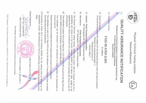
17 EU DECLARATION OF CONFORMITY Finish Thompson Inc. hereby declares that the following machines fully comply with the applicable health and safety requirements as specified by the EU Directives listed. This declaration is valid provided that the devices are fully assembled and no modifications are made to these machines. Type of Device: Drum or Container Pump Pump Models: PFS-27, PFS-40, PFS-48, PFS-60, PFS-72 EU Directives: Equipment and protective systems intended for use in potentially explosive atmospheres (2014/34/EU) EU-Type Examination: Physical Technical testing Institute 1026 Ostrava-Radvanice FTZU 04 ATEX 0293X Product Quality Assurance Notification: Physical Technical Testing Institute 1026 Ostrava-Radanice FTZU 08 ATEX Q 003 Applicable Harmonized Standards: EN : 2011 EN :2009 EN :2011 Signed, Casey D. Bowes CEO and President August 1,
18 EU DECLARATION OF CONFORMITY Finish Thompson Inc. hereby declares that the following machines fully comply with the applicable health and safety requirements as specified by the EU Directives listed. This declaration is valid provided that the devices are fully assembled and no modifications are made to these machines. Type of Device: Pump Motor Pump Motor Models: M10X EU Directives: Equipment and protective systems intended for use in potentially explosive atmospheres (2014/34/EU) EU-Type Examination: Physical Technical Testing Institute 1026 Ostrava-Radvanice FTZU 08 ATEX 0083X Product Quality Assurance Notification: Physical Technical Testing Institute 1026 Ostrava-Radanice FTZU 08 ATEX Q 003 Applicable Harmonized Standards: EN :2012 EN :2014 Signed, Casey D. Bowes CEO and President April 20, 2016

19 EU DECLARATION OF CONFORMITY Finish Thompson Inc. hereby declares that the following machines fully comply with the applicable health and safety requirements as specified by the EU Directives listed: Type of Device: Pump Motor Pump Motor Models: M6A, M6XA EU Directives: Equipment and Protective Systems Intended For Use In Potentially Explosive Atmospheres (2014/34/EU) Applicable Harmonized Standards: DIN EN :2011 DIN EN :2009 DIN EN : 2011 The products are marked with the following characteristics: II 2 GDc +1 o C Ta +40 o C Documentation archived in FTZÚ Ostrava Radviance, EU code 1026 This declaration is valid provided that the devices are fully assembled and no modifications are made to these machines. Casey D. Bowes CEO and President 20 April 2016
20 Service P/N Rev. 16, 5/19/2017
PF SERIES PUMPS PFS ATEX VERSION (INCLUDES M6A, M6XA, M10X MOTORS & SPK) OPERATION & PARTS MANUAL
 OPERATION & PARTS MANUAL") PF SERIES PUMPS PFS ATEX VERSION (INCLUDES M6A, M6XA, M10X MOTORS & SPK) OPERATION & PARTS MANUAL Introduction This manual pertains to the PF Series, specifically the ATEX version of the PFS stainless
PF SERIES PUMPS PFS ATEX VERSION (INCLUDES M6A, M6XA, M10X MOTORS & SPK) OPERATION & PARTS MANUAL Introduction This manual pertains to the PF Series, specifically the ATEX version of the PFS stainless
PF SERIES PUMPS PFS OPERATION & PARTS MANUAL
 PF SERIES PUMPS PFS OPERATION & PARTS MANUAL For Serial Number 162859 & above EU Declaration of Conformity Finish Thompson Inc. hereby declares that the following machine(s) fully comply with the applicable
TB SERIES PUMPS TBS OPERATION & PARTS MANUAL
 TB SERIES PUMPS TBS OPERATION & PARTS MANUAL EU Declaration of Conformity Finish Thompson Inc. hereby declares that the following machine(s) fully comply with the applicable health and safety requirements
TM SERIES MIXER TMS OPERATION & PARTS MANUAL
 TM SERIES MIXER TMS OPERATION & PARTS MANUAL EU Declaration of Conformity Finish Thompson Inc. hereby declares that the following machine(s) fully comply with the applicable health and safety requirements
TBP SERIES PUMPS OPERATION & PARTS MANUAL
 TBP SERIES PUMPS OPERATION & PARTS MANUAL EU Declaration of Conformity Finish Thompson Inc. hereby declares that the following machine(s) fully comply with the applicable health and safety requirements
EF SERIES PUMPS OPERATION & PARTS MANUAL
 EF SERIES PUMPS OPERATION & PARTS MANUAL EU Declaration of Conformity Finish Thompson Inc. hereby declares that the following machine(s) fully comply with the applicable health and safety requirements
PF SERIES PUMPS PFM, PFP, PFV OPERATION, INSTALLATION & PARTS MANUAL
 PF SERIES PUMPS PFM, PFP, PFV OPERATION, INSTALLATION & PARTS MANUAL EU Declaration of Conformity Finish Thompson Inc. hereby declares that the following machine(s) fully comply with the applicable health
EF SERIES MOTORS OPERATION & PARTS MANUAL
 EF SERIES MOTORS OPERATION & PARTS MANUAL Models S1, S2, S3, S4 S1, S2, S3 S4 EU Declaration of Conformity Finish Thompson Inc. hereby declares that the following motors fully comply with the applicable
PF SERIES PUMPS PFM, PFP, PFV OPERATION, INSTALLATION & PARTS MANUAL
 PF SERIES PUMPS PFM, PFP, PFV OPERATION, INSTALLATION & PARTS MANUAL EU Declaration of Conformity Finish Thompson Inc. hereby declares that the following machine(s) fully comply with the applicable health
MV Series Motors Operation & Parts Manual
 MV Series Motors Operation & Parts Manual Models M3V, M5V, M5V-US For use with M3V s/n 101057 & below, M3V-UK s/n 103013 & below, M5V & M5V-US s/n 102972 & below. EU Declaration of Conformity Finish Thompson
EF SERIES EFS ATEX VERSION (INCLUDES OPTIONAL S4A MOTOR & SPK) OPERATION & PARTS MANUAL
 OPERATION & PARTS MANUAL") EF SERIES EFS ATEX VERSION (INCLUDES OPTIONAL S4A MOTOR & SPK) OPERATION & PARTS MANUAL Introduction This manual pertains to the EF Series, specifically the ATEX version of the EFS stainless steel drum
EF SERIES EFS ATEX VERSION (INCLUDES OPTIONAL S4A MOTOR & SPK) OPERATION & PARTS MANUAL Introduction This manual pertains to the EF Series, specifically the ATEX version of the EFS stainless steel drum
MV Series Motors Operation & Parts Manual. Models M3V, M5V, M5V-US
 MV Series Motors Operation & Parts Manual Models M3V, M5V, M5V-US Introduction This manual pertains to drum pump motors MV Series. Finish Thompson, Inc. thanks you for choosing our products. We believe
EF SERIES PUMPS EFP, EFS, & EFV OPERATION & PARTS MANUAL
 EF SERIES PUMPS EFP, EFS, & EFV OPERATION & PARTS MANUAL EU Declaration of Conformity Finish Thompson Inc. hereby declares that the following machine(s) fully comply with the applicable health and safety
S Series Motors. Model S6 * Operation & Parts Manual. For EF Series Pump Tubes Only. Patent pending.
 S Series Motors Model S6 * Operation & Parts Manual For EF Series Pump Tubes Only * Patent pending. EU Declaration of Conformity Finish Thompson Inc. hereby declares that the following electrical equipment
OPERATION AND PARTS MANUAL
 OPERATION AND PARTS MANUAL DRUM PUMPS AND MOTORS HVDP SERIES 1 TABLE OF CONTENTS Introduction...3 Warranty...3 Chemical Reaction Disclaimer...3 Return Policy...3 Safety Precautions...4 Maintenance Precautions...4
User s Guide XXXXXX. Xxxxx Xxxxxxxx. Shop online at. omega.com For latest product manuals: omegamanual.info
 User s Guide Shop online at omega.com e-mail: info@omega.com For latest product manuals: omegamanual.info XXXXXX Xxxxx Xxxxxxxx OMEGAnet Online Service omega.com Internet e-mail info@omega.com Servicing
ALITA LINEAR AIR PUMP OPERATION & MAINTENANCE MANUAL. AL- Model Number Date Code / Serial Number Date of Purchase
 ALITA LINEAR AIR PUMP OPERATION & MAINTENANCE MANUAL AL- Model Number Date Code / Serial Number Date of Purchase LIMITED WARRANTY ALITA warrants to the original retail consumer purchaser ( Customer ) that
AK / AV 4 & 5 SERIES Metallic Vertical Centrifugal Pumps Installation and Maintenance Instructions
 AK / AV 4 & 5 SERIES Metallic Vertical Centrifugal Pumps Installation and Maintenance Instructions ASSEMBLY PUMPS WITH MOTORS 1. No assembly required. Simply unpack the pump and motor and examine for any
Air Operated Diaphragm Pumps Operating and Maintenance Instructions
 Product & Chemical Disclaimer The user must take responsibility in the selection of the products materials of construction. Empire Pumps Ltd will act in an advisory role and offer recommendations; however,
KC 5.5, 6, 6H, 7, 8, & 10 SERIES Non-Metallic Centrifugal Pumps Installation and Maintenance Instructions
 KC 5.5, 6, 6H, 7, 8, & 10 SERIES Non-Metallic Centrifugal Pumps Installation and Maintenance Instructions ASSEMBLY Unpack the pump, drive magnet assembly and hardware package from carton and check for
OWNER/OPERATOR MANUAL. Airmotor effective dia. in. 2.5
 MODELS 282050, 282716 & 283513 AIR OPERATED CHASSIS PUMP SERIES A OWNER/OPERATOR MANUAL SPECIFICATIONS Airmotor effective dia. in. 2.5 Airinlet Material outlet 1/4 NPTF 1/4 NPTF Liquid to Air Pressure
Air Operated Double Diaphragm Pump. M-Pump ½ Metallic Non Metallic Pump INSTALLATION, OPERATION & MAINTENANCE MANUAL
 Air Operated Double Diaphragm Pump M-Pump ½ Metallic Non Metallic Pump INSTALLATION, OPERATION & MAINTENANCE MANUAL 0.5 I.O.M rev 05. 12/2015 INDEX Title Section Introduction.1 Safety.2 Warranty, General
PUMP-FIT MODEL SERIES PF Assembly, Installation and Operation Manual
 PUMP-FIT MODEL SERIES PF66605 Assembly, Installation and Operation Manual EU Declaration of Conformity Pump-Fit hereby declares that the following machine(s) fully comply with the applicable health and
4. All Federal, State, and local safety codes should be followed.
 Standard Pump Description Standard s Drum Pumps are designed to transfer a variety of materials from 55 gallon drums and tanks. Standard Pump offers several different pumps, each designed for specific
Colt Series C400, C500
 Colt Series C400, C500 RP/IS-A-C400/C500 C400 OSY Reduced Pressure Zone Assemblies Reduced Pressure Detector Assemblies Sizes: 2 1 2" 10" (65 250mm) Installation Service Repair Kits Maintenance For other
Model FM1000 Series Operating Instructions. Drum Pump Flow Meter
 Model FM1000 Series Operating Instructions Drum Pump Flow Meter Table of Contents Safety... 1 Introduction... 1 Specificatons... 1 Features... 1 Section 1 - Installation... 2 Section 2 - Operation... 2
Series 957, 957N, 957Z, 957RPDA, 957NRPDA, 957ZRPDA
 Series 957, 957N, 957Z, 957RPDA, 957NRPDA, 957ZRPDA Reduced Pressure Zone Assemblies Reduced Pressure Detector Assemblies Sizes: 2 1 2" 10" (65 250mm) Installation Service Repair Kits Maintenance RP/IS-957/957RPDA
Centrifugal Drum Pump Motor Models: SP-410EX, SP-420EX, SP-280P, SP-ENC, SP-A1 & SP-A2
 Standard Pump Standard s Drum Pumps are designed to transfer a variety of materials from 55 gallon drums and tanks. Standard Pump offers several different pumps, each designed for specific applications.
BMRX Series ROTARY LEVEL CONTROL
 BMRX Series ROTARY LEVEL CONTROL OPERATING INSTRUCTIONS PLEASE READ CAREFULLY 925-0292 Rev C TABLE OF CONTENTS GENERAL SPECIFICATIONS... 3 SAFETY SUMMARY... 4 1.0 INTRODUCTION... 5 2.0 INSTALLATION...
Nilfisk-CFM SS Vapor Vacuum Instructions for Use and Spare Parts Manual
 Nilfisk-CFM SS Vapor Vacuum Instructions for Use and Spare Parts Manual Caution: This Nilfisk-CFM vacuum cleaner is not to be used in explosion hazardous areas as serious injury could result. Your new
VKC5.5,6,6H, 7,8,10 SERIES Sealless Non-Metallic Vertical Pumps Installation and Maintenance Instructions. Pat.No. 5,708,313
 ASSEMBLY WARNING: Magnetic field hazard. This pump contains powerful rare earth magnets. When the pump is disassembled (not connected to a motor) and the magnets are exposed, these magnets produce powerful
MetroPrime 22MPC Self-Priming Centrifugal Pump
 Page 1 of 6 prevent priming or reduce pump capacity. OPERATION The 22 MPC-Metropolitan Pump is a self-priming centrifugal pump and only requires priming prior to its initial start. The pump will retain
Operation Manual FLG-G5 Transtech Gravity Spray Gun SB-E ISS.05
 Operation Manual FLG-G5 Transtech Gravity Spray Gun SB-E-2-790 ISS.05 Operation Manual FLG5 Gravity-feed Spray Gun Important Read and follow all instructions and Safety Precautions before using this equipment
4000SS. For other repair kits and service parts, send for Ames Repair Parts Price List, PL-A-RP-BPD.
 Series 4000SS RP/IS-A-4000SS 4000SS Reduced Pressure Zone Assemblies Sizes: 8" 10" (200 250mm) Installation Service Repair Kits Maintenance For other repair kits and service parts, send for Ames Repair
1. Before operating the pump, read and understand these operating instructions.
 Standard Pump Description Standard s Drum Pumps are designed to transfer a variety of materials from 55 gallon drums and tanks. Standard Pump offers several different pumps, each designed for specific
Watts Series CSM-91. Grooved/Flanged Flow Measurement/Balancing Valves. Installation and Operating Instructions. Table of Contents. 1.
 Watts Series CSM-9 Grooved/Flanged Flow Measurement/Balancing Valves Installation and Operating Instructions IS-CSM-9 Table of Contents Item Description Page. Installation of Valve Angle Design 2. Installation
Operator s Manual. Nitro 1000 Nitro 1000X. Nitro 750 Nitro 750X. September REV0
 Operator s Manual Nitro 750 Nitro 750X Nitro 1000 Nitro 1000X September.27.2018REV0 Table of Contents Introduction...3 Safety.....4 Equipment Requirements......5 What You Have Received. 5 Serial Number...6
Model AS-FM64 Wall Mount. Full Motion Television Wall Mount
 Model AS-FM64 Wall Mount Full Motion Television Wall Mount Getting Started Introduction Congratulations on the purchase of your new Audio Solutions AS-FM64 Television Wall Mount. For maximum benefit, please
FCB-450, LCB-600, MCB-800
 AIR CHAMP PRODUCTS User Manual FCB-450, LCB-600, MCB-800 Clutch-Brakes (i) In accordance with Nexen s established policy of constant product improvement, the specifications contained in this manual are
Straight-Bore Clutch LSCC-32, 44, 54
 Straight-Bore Clutch LSCC-32, 44, 54 1 In accordance with Nexen s established policy of constant product improvement, the specifications contained in this manual are subject to change without notice. Technical
BC Brake Caliper. (i) MEX (55) QRO (442) MTY (81) DIST. AUTORIZADO
 MEX (55) QRO (442) MTY (81) DIST. AUTORIZADO") MEX (55) 5 6 QRO (44) 95 7 60 MTY () 54 0 BC Brake Caliper (i) FORM NO. L-0066-B-040 In accordance with Nexen s established policy of constant product improvement, the specifications contained in this
MEX (55) 5 6 QRO (44) 95 7 60 MTY () 54 0 BC Brake Caliper (i) FORM NO. L-0066-B-040 In accordance with Nexen s established policy of constant product improvement, the specifications contained in this
Operating and Installation Instructions
 Model Number 20902 Fabricator's Power Module Kit - Aluminum Operating and Installation Instructions CAUTION! This product is to be installed only by persons knowledgeable in the repair and modification
Telescopic Transmission Jacks
 Telescopic Transmission Jacks Operating Instructions & Parts Manual Model Number BH7051 BH7055 (Air/Manual) Capacity 1/2 Ton 1/2 Ton SFA Companies 2006 10939 N. Pomona Ave. Kansas City, MO 64153 816-891-6390
Sample Pro 3/4" Portable MicroPurge Pump. User's Guide P/N REV The World Leader in Air Powered Pumps
 PATENT PENDING Pro 3/4" Portable MicroPurge Pump User's Guide P/N 959 REV. -8-03 The World Leader in Air Powered For Remediation, Landfills and Ground Water Sampling Ground water Sampling Remediation,
Hydraulic Transmission Jacks
 Hydraulic Transmission Jacks Operating Instructions & Parts Manual Model Number Atd-7435 Atd-7436 Atd-7437 Capacity 1100 Lb. 2000 Lb. 3000 Lb. Model Atd-7435 Model Atd-7436 Model Atd-7437 Atd Tools Inc.
Solutions beyond products...
 ORIGINAL INSTRUCTIONS IH102C Installation, Operation & Maintenance Manual Model B177 External Automatic Bypass Valve Model B177 External Automatic Bypass Valve Warning: (1) Periodic inspection and maintenance
Models: 8500, 8501, 8513, 8514, 8500BL, 8501BL, 8513BL, 8514BL, 8540, 8541, 8550, 8551, 8540BL, 8541BL, 8550BL & 8551BL
 Standard Pump Ultra Mass High Viscosity Batch Control System Description Standard s Drum Pumps are designed to transfer a variety of materials from 55 gallon drums and tanks. Standard Pump offers several
Elgin Hydraulic Clutch-Brake ECB-240, Product Number FORM NO. L F FORM NO. L F-0704
 Elgin Hydraulic Clutch-Brake ECB-20, Product Number 96225 FORM NO. L-20283-F-070 1 FORM NO. L-20283-F-070 In accordance with Nexen s established policy of constant product improvement, the specifications
DeZURIK 2 20" BOS BUTTERFLY VALVES
 2 20" BOS BUTTERFLY VALVES Instruction D10459 October 2013 2-20 BOS Butterfly Valves Instructions These instructions provide information about BOS Butterfly Valves. They are for use by personnel who are
LUBRICATOR GUN INSTRUCTIONS-PARTS LIST. 10,000 psi (700 bar) Maximum Delivery Pressure. Detachable-type
 Maximum Delivery Pressure. Detachable-type") INSTRUCTIONS-PARTS LIST 306 460 INSTRUCTIONS This manual contains important warnings and information. READ AND KEEP FOR REFERENCE. Rev. E Supercedes D Detachable-type LUBRICATOR GUN 10,000 psi (700 bar)
INSTRUCTIONS-PARTS LIST 306 460 INSTRUCTIONS This manual contains important warnings and information. READ AND KEEP FOR REFERENCE. Rev. E Supercedes D Detachable-type LUBRICATOR GUN 10,000 psi (700 bar)
Old Proportioning Pumps
 Repair - Parts Old Proportioning Pumps 311391F For proportioning pumps on Gusmer and Old Graco H-25 and H-XP2 Hydraulic Proportioners. Important Safety Instructions Read all warnings and instructions in
SERIES FE MAGNETIC COUPLED PUMPS
 SERIES FE MAGNETIC COUPLED PUMPS Refer to Bulletin P-518 O-2804 TABLE OF CONTENTS Description Page Number Important Information...3 Chemical Reaction Disclaimer...3 Safety Precautions...3 Installation/Operation
AGITATED LID ASSEMBLY
 SERVICE MANUAL EN 31-425 AGITATED LID ASSEMBLY 41-3312, 41-3312-S DIRECT DRIVE AGITATORS 77-1474-R20 (3/2018) 1 / 8 www.carlisleft.com AGITATOR ASSEMBLY FOR 25 Litre (5 Gal.) PAIL IMPORTANT: Read and follow
Easytork Solenoid Valve IOM
 Easytork Solenoid Valve IOM General This installation document is to be read in conjunction with the Easytork Vane Actuator IOM. Description The Easytork Solenoid Valve ( ESV ) series is intended for the
PENBERTHY MODELS GL AND GH GAS OPERATED JET PUMPS INSTALLATION, OPERATION AND MAINTENANCE INSTRUCTIONS
 Before installation, these instructions must be read carefully and understood. PRODUCT WARRANTY Emerson warrants its Penberthy products as designed and manufactured to be free of defects in the material
Operation Manual Cobra 1 Automatic Spray Gun
 SB-E-2-CBA1 ISS.06 Operation Manual Cobra 1 Automatic Spray Gun E P 1 12 1 Operation Manual Cobra 1 Automatic Spraygun Important Read and follow all instructions and Safety Precautions before using this
POLYPROPYLENE PUMP TUBE SP-PP SERIES
 POLYPROPYLENE PUMP TUBE SP-PP SERIES * * * 0 * V-seal - Viton Pump coupling Drive shaft, " (00 mm) Discharge housing Bearing unit assembled - each Viton shielded bearings, spacer, snap ring, bearing can
ROUSH Short Throw Shifter Kit
 ROUSH Short Throw Shifter Kit Part Number 1310R7400 Application: 2010 Ford Mustang GT Installation Instructions Before installing your ROUSH Performance Product(s), read through the entire installation
OWNER S MANUAL EVOLUTION 3500, 4500, 5500, & 8500 SERIES PUMPS
 OWNER S MANUAL EVOLUTION 3500, 4500, 5500, & 8500 SERIES PUMPS IMPORTANT SAFETY INSTRUCTIONS When installing and using this electrical equipment, basic safety precautions should always be followed, including
Model FMBC3000 Series Operating Instructions. Drum Pump Flow Meter
 Model FMBC3000 Series Operating Instructions Drum Pump Flow Meter Table of Contents Safety... 1 Introduction... 1 Specificatons... 1 Features... 1 Section 1 - Installation... 2 Section 2 - Operation...
Models: 8500, 8501, 8513, 8514, 8500BL, 8501BL, 8513BL, 8514BL, 8540, 8541, 8550, 8551, 8540BL, 8541BL, 8550BL & 8551BL
 Standard Pump Ultra Mass High Viscosity Batch Control System Description Standard s Drum Pumps are designed to transfer a variety of materials from 55 gallon drums and tanks. Standard Pump offers several
USER MANUAL. NEMA 48C Flange Mounted, Enclosed, Clutch Brake. FMCBE Model 500 FORM NO. L A (i)
") USER MANUAL NEMA 48C Flange Mounted, Enclosed, Clutch Brake FMCBE Model 500 (i) In accordance with Nexen s established policy of constant product improvement, the specifications contained in this manual
USER MANUAL NEMA 48C Flange Mounted, Enclosed, Clutch Brake FMCBE Model 500 (i) In accordance with Nexen s established policy of constant product improvement, the specifications contained in this manual
Air Actuated Hydraulic Bottle Jacks
 Air Actuated Hydraulic Bottle Jacks Operating Instructions & Parts Manual Model Number Atd-7412 Atd-7420 Capacity 12 Ton 20 Ton Atd Tools Inc. 160 Enterprise Drive, Wentzville MO 63385 Printed in China
CRD610 Automatic Fitting Inserter
 CRD610 Automatic Fitting Inserter OPERATIONS MANUAL VERSION 1.2 LAST EDITED 12.12.2018 cleanroomdevices.com 1 Table of Contents Title Page. 1 Table of Contents...2 1.0 General Product & Safety Information....3
Artesian2 Owners Manual
 Artesian2 Owners Manual Energy-Efficient, Self Priming Centrifugal Pumps Discharge Inlet Important Safety Instructions Please read all instructions completely before you install or operate your new pump.
JD-2 TOLL FREE UG August /2011
 Instructions Manual Office Phone: 1-800-503-7534 / 305-868-1603 Fax: 305-866-2704 sales@skyfood.us - www.skyfood.us Warehouse Phone: 1-800-445-6601 / 973-482-5070 Fax: 973-482-0725 Juice Dispenser Model
Artesian Owners Manual
 Artesian Owners Manual Energy-Efficient, Self Priming Centrifugal Pumps Discharge Inlet Important Safety Instructions Please read all instructions completely before you install or operate your new pump.
Operating Instructions
 Operating Instructions WARNING: Do not attempt to assemble, connect to power source, or operate the Burrell Wrist-Action Shaker without first reading these instructions. Also assure that each person that
OPERATING INSTRUCTIONS PLEASE READ CAREFULLY
 OPERATING INSTRUCTIONS PLEASE READ CAREFULLY 925-0330 Rev 0 0416 TABLE OF CONTENTS SAFETY SUMMARY... 3 SPECIFICATIONS... 4 1.0 INTRODUCTION/DESCRIPTION.... 5 2.0 LOCATION AND MOUNTING... 5 3.0 CONNECTIONS
CONTENTS. VIKING PUMP, INC. A Unit of IDEX Corporation Cedar Falls, IA USA SECTION TSM 710.1
 TECHNICAL SERVICE MANUAL industrial heavy duty motor speed pumps SERIES 4076 AND 4176 SIZES hle, ate and ale SECTION TSM 710.1 PAGE 1 of 8 ISSUE B CONTENTS Introduction....................... 1 Safety
MODEL BARE REEL SERIES E
 MODEL 84275 BARE REEL SERIES E SPECIFICATIONS Maximum working pressure 5000 p.s.i. Material Inlet 1/2 NPT (Female) Material outlet 1/2 NPT (Female) Sheave width 10 Sheave diameter 19-1/4 Drum diameter
INSTALLATION INSTRUCTION & OWNER S MANUAL
 CS-2500 & CS-2500P Water Filtration System INSTALLATION INSTRUCTION & OWNER S MANUAL Ver 1.2 All Rights Reserved APEC Water Systems Please keep this Owner s Manual for future reference. It contains useful
ALUMAREEL. Electrical Cord Reel. Model EC6 100 Model EC Operational, Maintenance and Installation Manual
 ALUMAREEL TM Electrical Cord Reel Model EC6 100 Model EC3 100 Operational, Maintenance and Installation Manual READ AND UNDERSTAND THIS MANUAL BEFORE USING THIS PRODUCT. RETAIN FOR FUTURE REFERENCE 1 P
PENBERTHY FROST PROOF EXTENSION INSTALLATION, OPERATION AND MAINTENANCE INSTRUCTIONS
 Before installation these instructions must be read fully and understood PRODUCT WARRANTY Emerson warrants its Penberthy products as designed and manufactured to be free of defects in the material and
Read this entire manual before operation begins.
 Read this entire manual before operation begins. Record below the following information which is located on the serial number data plate. Serial No. Model No. Date of Installation Contents Specifications.............
 CUSTOMER SERVICE: 800-973-8374 Frame Assembly Instructions Headboard Installation E 1. Use the remote control to raise the head of the adjustable foundation in order to gain access to the foundation
Manual PN: Rev 01. Otterbine Barebo Inc. Fractional Series 50Hz Installation Manual
 Manual PN: 75-0009 Rev 01 Otterbine Barebo Inc. Fractional Series 50Hz Installation Manual SAFETY INSTRUCTIONS ALL ELECTRICAL WORK MUST BE PERFORMED BY A QUALIFIED LICENSED ELECTRICIAN AND CONFORM WITH
DP-139 PUMP DIMENSIONS
 3/2019 Table of Contents NOTES TO THE OWNER... 3 SELECTION OF PUMP AND EQUIPMENT DESIGN... 3 SAFETY PRECAUTIONS... 3 WARNING... 4 INSTALLATION SCHEME... 5 ORDINARY MAINTENANCE FOR DIAPHRAGM PUMPS... 6-7
Operation & Service Manual
 Operation & Service Manual Model: 02-1248-0112 12 Ton Single Stage Jack 11/2004 Rev. 02 Includes Illustrated Parts Lists 1740 Eber Rd Tronair, Inc. Phone: (419) 866-6301 Holland, OH 43528-9794 www.tronair.com
TECHNICAL SERVICE MANUAL
 Electronic copies of the most current TSM issue can be found on the Viking Pump website at www.vikingpump.com TECHNICAL SERVICE MANUAL industrial heavy duty motor speed pumps SERIES 4076 AND 4176 SIZES
DAP-625S and DAP-875S
 AIR CHAMP PRODUCTS DAP-625S and DAP-875S (i) FORM NO. L-20078-B-0501 In accordance with Nexen s established policy of constant product improvement, the specifications contained in this manual are subject
Pressurized oil drain for collection of used lubricants and anti-freeze.
 Instructions - Parts List 24-Gallon (90-Liter) Oil Ace 30864B Pressurized oil drain for collection of used lubricants and anti-freeze. Model 9577 Series A 8 psi (55 kpa,5 bar) Maximum Working Pressure
Stainless Steel Air Motor Conversion Kits
 Instructions Stainless Steel Air Motor Conversion Kits 096D Conversion Kit 650 For 00 Pumps Conversion Kit 65 For 590 Pumps Conversion Kit 65 For 50 Pumps Model 650 Model 65 Model 65 Installation Pressure
Operating Instructions
 Operating Instructions Repair Light > Contents 1 Contents 1 Contents...2 2 General Information...2 3 General Safety Information...3 4 Designated Use...4 5 Technical Data...4 6 Transport, Storage and Disposal...6
Merkur Displacement Pump
 Repair/Parts Merkur Displacement Pump 32792G EN For use with high-performance finishing and coating pumps in hazardous and non-hazardous locations. For professional use only. Important Safety Instructions
Hayes Performance Systems 5800 W. Donges Bay Rd. Mequon, WI Tel: Web:
 PRO/Comp Hayes Performance Systems 5800 W. Donges Bay Rd. Mequon, WI 53092 Tel: 888.686.3472 Email: techsupport@hayesbicycle.com Web: www.hayescomponents.com Hayes Components Europe Dirnismaning 20 a 85748
Model AS-RC3260 TV Cart. Rolling Cart for Audio Mount System & Flat Panel TVs
 Model AS-RC3260 TV Cart Rolling Cart for Audio Mount System & Flat Panel TVs GETTING STARTED Introduction Congratulations on the purchase of your new Helios AS-RC3260 Rolling Cart. For maximum benefit,
DELTA O-RING CARTRIDGE SEAL ASSEMBLY AND INSTALLATION INSTRUCTIONS INTRODUCTION:
 DELTA O-RING CARTRIDGE SEAL ASSEMBLY AND INSTALLATION INSTRUCTIONS INTRODUCTION: These instructions are provided to familiarize the user with the seal and its use. The instructions must be read carefully
PREDICTIVE STEERING HUBS. Service Manual
 2015 PREDICTIVE STEERING HUBS Service Manual SRAM LLC WARRANTY EXTENT OF LIMITED WARRANTY Except as otherwise set forth herein, SRAM warrants its products to be free from defects in materials or workmanship
18VDC ESB6 Series Cordless Screwdrivers Operation Manual
 18VDC ESB6 Series Cordless Screwdrivers Screwdriver Models : ESB6-8, ESB6-12, ESB6-15, ESB6-22 CAUTION - Please read, understand, and follow all operating and safety instructions in this manual before
Air Actuated Hydraulic Bottle Jack on Wheels
 Operating Instructions & Parts Manual Air Actuated Hydraulic Bottle Jack on Wheels Model Number 18127 18207 Capacity 12 Ton 20 Ton Shinn Fu Co. of America, Inc. 2002 10939 N. Pomona Avenue Kansas City,
Stainless Steel Air Motor Conversion Kits
 Instructions Stainless Steel Air Motor Conversion Kits 096B Conversion Kit 650 For 00 Pumps Conversion Kit 65 For 590 Pumps Conversion Kit 65 For 50 Pumps Model 650 Model 65 Model 65 Graco Inc. P.O. Box
Otte. erbine Frac. ctiona anuall
 Otte erbine e Barrebo Inc. Frac ctiona al Series CE Insta I anuall llation Ma Manu ual PN: 75-00 010 Rev 01 SAFETY ALL ELECTRICAL WORK MUST BE PERFORMED BY A QUALIFIED LICENSED ELECTRICIAN AND CONFORM
operating instruction
 operating instruction a.560pn #125101 DE, EN, FR, SE Table of Contents Installation... 3 Tool use...4-5 Safety precautions...6-7 Troubleshooting and maintenance... 8 Technical specification... 9 Spare
ROUSH Performance Air Induction Kit Pt # R
 ROUSH Performance Air Induction Kit Pt # R07060087 C. A. R. B. EO # D-418-14 See Important EO Note below Included with your ROUSH Intake System Kit is a sticker with a California Air Resources Board (C.
LABORATORY DISPERSERER
 LABORATORY DISPERSERER OWNERS MANUAL DS4000 SERIES DISPERSERERS Contents: Page: Warranty: Our products are guaranteed against defective materials and workmanship. We will repair or replace such items as
CRD400 Fitting Inserter OPERATIONS MANUAL
 CRD400 Fitting Inserter OPERATIONS MANUAL ORIGINAL INSTRUCTIONS VERSION 3.4 LAST EDITED 01.07.2019 www.cleanroomdevices.com 1 Table of Contents Title Page.. 1 Table of Contents... 2 1.0 General Product
25 GALLON PORTABLE OIL LIFT
 25 GALLON PORTABLE OIL LIFT Model 92859 SET UP AND OPERATING INSTRUCTIONS Diagrams within this manual may not be drawn proportionally. Due to continuing improvements, actual product may differ slightly
AIR CHAMP PRODUCTS. User Manual. Sheave & Pilot Mount Clutch-Brake Model BCB-275 FORM NO. L F-0414 FORM NO. L F-0414
 AIR CHAMP PRODUCTS User Manual Sheave & Pilot Mount Clutch-Brake Model BCB-275 i In accordance with Nexen s established policy of constant product improvement, the specifications contained in this manual
OPERATING INSTRUCTIONS ZDX 7-1/2AS
 OPERATING INSTRUCTIONS ZDX 7-1/2AS www. sethco. com info@sethco.com INDEX Warranty 2 Safety Rules 3 Operating Instructio ns 4 General Description 4 Pre-installation 4 Pump Installation 4 Piping the Pump