EF SERIES EFS ATEX VERSION (INCLUDES OPTIONAL S4A MOTOR & SPK) OPERATION & PARTS MANUAL
|
|
|
- Sherman Dickerson
- 5 years ago
- Views:
Transcription


1 EF SERIES EFS ATEX VERSION (INCLUDES OPTIONAL S4A MOTOR & SPK) OPERATION & PARTS MANUAL
2 Introduction This manual pertains to the EF Series, specifically the ATEX version of the EFS stainless steel drum pump. Finish Thompson Inc. thanks you for choosing our products. We believe the use of our products will be fully satisfactory. When properly installed and operated, your Finish Thompson motor and pump will provide long, trouble-free service; therefore, please read this manual carefully before carrying out any operations on the pump/motor unit. Any use other than that described herein is considered incorrect; and, consequently, Finish Thompson Inc. shall not be held responsible for any damages to people or property. In case of doubt or enquiries, please reply to our Technical Service department directly at the following address: Finish Thompson, Inc. 921 Greengarden Rd. Erie, PA U.S.A. Tel ; Fax Index Introduction...2 Warranty, General Terms & Conditions...3 Safety Pump Specifications...5 ATEX Specifications...6 EFS Installation...7 Static Protection Kit Assembly Operation...8 Maintenance Disassembly Inspection...9 Reassembly Exploded Views...11 Pump Tube Spare Parts List...12 S4A Spare Parts List & View...13 ATEX Certificates...14 CE Certificates of Conformity Technical Service Hotline: or 2
3 Warranty, General Terms & Conditions 1. The following terms and conditions apply to the sale of machinery, components and related services and products, of Finish Thompson Inc. (hereinafter the products ) 2. Finish Thompson Inc. (the manufacturer) warrants only that: a) its products are free of defects in material, design and workmanship at the time of original purchase; b) its products will function in accordance with Finish Thompson Inc. operation manuals; Finish Thompson Inc. does not guarantee that the product will meet the precise needs of the Customer, except for those purposes set out in any invitation to render documents or other documents specifically made available to Finish Thompson Inc. before entering into this agreement; c) high quality materials are used in the construction of the pumps and that machining and assembly are carried out to the highest standards. Except as expressly stated above, Finish Thompson Inc. makes no warranties, express or implied, concerning the products, including all warranties of fitness for a particular purpose. This warranty shall not be applicable in circumstances other than defects in material, design, and workmanship. In particular warranty shall not cover the following: d) Periodic checks, maintenance, repair and replacement of parts due to normal wear and tear; e) Damage to the product resulting from: i. Tampering with, abuse or misuse, including but not limited to failure to use the product for its normal purposes as stated at the time of purchase or in accordance with Finish Thompson, Inc. instructions for use and maintenance of the product, or the installation or improper ventilation or use of the product in a manner inconsistent with the technical or ii. safety standard in force; Repairs performed by non-authorized service workshop, or opening of the unit by non-authorized personnel, or use of non genuine Finish Thompson Inc. parts; iii. Accidents, force majeure or any cause beyond the control of Finish Thompson Inc., including but not limited to lightning, water, fire, earthquake, and public disturbances, etc. 3. The warranty shall cover the replacement or repair of any part, which is documented to be faulty due to construction or assembling, with new or repaired parts free of charge delivered by Finish Thompson, Inc. Parts subjected to normal wear and tear shall not be covered by the warranty. Finish Thompson, Inc. shall decide as to whether the defective or faulty part shall be replaced or repaired. Transportation charges are prepaid to Finish Thompson. 4. The warranty of the products shall be valid for a period of 12 months from the date of delivery, under the condition that notice of the alleged defect to the products or parts thereof be given to Finish Thompson, Inc. within the term of 8 days from the discovery. 5. Repair or replacement under the terms of this warranty shall not give a right to an extension to, or a new commencement of, the period of warranty. Repair or replacement under the terms of this warranty may be fulfilled with functionally equivalent reconditioned units. Finish Thompson Inc. qualified personnel shall be solely entitled to carry out repair or replacement of faulty parts after careful examination of the motor. Faulty parts or components when replaced by Finish Thompson Inc. will become the property of Finish Thompson Inc. If this warranty does not apply, the purchaser shall bear all cost for labor, material and transportation. 6. Finish Thompson Inc. will not be liable on any claim, whether in contact, tort, or otherwise, for any indirect, special, incidental, or consequential damages, caused to the customer or to third parties, including loss of profits, process down time, transportation costs, costs associated with replacement or substitution products, labor costs, installation or removal costs. In any and all events, manufacturer s liability shall not exceed the purchase price of the product and/or accessories. 7. Return Policy. Should you have any problems with this product, please contact the distributor in your area. The distributor will determine if a return to the factory is necessary and will contact the factory for a Return Authorization Number. Otherwise, contact our Technical Service Hotline ( ) or techservice@finishthompson.com if you have any questions regarding product operation or repair. 3
4 1. Introduction Safety This manual contains all the information needed for the correct installation, use and maintenance of your new Finish Thompson pump. It should be read and understood by all the personnel involved in installation, operating and servicing of the pump before it is started. 2. Operator Qualification and Training The personnel in charge of the installation, the operation, and the maintenance of the pump must be qualified and able to perform the operations described in this manual. Finish Thompson, Inc. shall not be held responsible for the training level of personnel and for the fact that they are not fully aware of the contents of this manual. 3. Safety Instructions FOR YOUR OWN SAFETY BEFORE using or servicing your pump, please make sure to wear the proper clothing, eye protection and follow standard safety procedures when handling corrosive or personally harmful materials. GENERAL DANGER ALWAYS use a Model EFS ATEX pump tube with a Model S4A air motor. A grounded discharge hose and grounding wire are also required and must be connected according to these instructions under the section below titled Static Protection Kit Assembly. Finish Thompson Inc. recommends using their Static Protection Kit with grounded discharge Hose P/N Similar to the Finish Thompson Static Protection Kit with grounded discharge Hose, any customer supplied grounded discharge hose must ensure a fluid velocity less than 1m/s (3.2ft./s.) and compliance with EN and CLC/TR ALWAYS use and store the pump and motor in an upright position. NEVER use in pressurized containers. ALWAYS use a chemically compatible hose rated for the temperature of the product being pumped. ALWAYS select the proper o-ring material. Improper material selection could lead to swelling and be a possible source of leaks. This is the responsibility of the end user. ALWAYS check the pump for leaks on a regular basis. If leaks are noticed, the pump must be repaired or replaced immediately. ALWAYS clean the pump on a regular basis to avoid any dust buildup greater than 5mm deep. ALWAYS check compatibility and temperature range of pump with liquids used. A Chemical Resistance and Material Selection Guide can be downloaded from our website at NEVER run dry. NEVER use with liquids containing solids that can damage the internals (i.e. metal chips) without optional strainer. ALWAYS flush unit with water after each use. ALWAYS store unit upright, i.e. motor above pump, and away from corrosive liquids and vapors. ALWAYS check bearings, bushings, & sleeves for signs of grinding, abnormal noise, overheating, or other signs of premature failure on a daily basis. Bearings, bushings, & sleeves should be replaced at the first sign of failure. Ensure the impeller spins freely by hand and does not bind. ALWAYS check the pump after an impact or drop. Ensure the tube and shaft are not bent and the impeller spins freely by hand without binding. Excessive running vibration may indicate a bent tube or shaft. Replace any bent or damaged components prior to operation. ALWAYS check that all hardware is tightly fastened to ensure the motor is securely attached to the pump. ALWAYS when using an air motor, use an automatic airline lubricator, moisture trap, and filter in the airline before the motor (use SAE#10 oil in the lubricator). Adjust lubricator to feed one drop of oil per minute of continuous run time. Do not exceed 40 psi (2.8 bar) on S4A. Maximum air consumption: S4A = 27 cfm (12.5 lps). DANGER: POWER SUPPLY Refer to instructions in this manual. 4
5 4. Noise Level 78 db at a distance of 3 feet (approximately 1 meter). 5. Modifications and Spare Parts Any changes concerning the service of the pump as originally purchased can be executed only after written approval from Finish Thompson Inc. It is recommended to use only genuine Finish Thompson Inc. spare parts and approved accessories. The use of non-original spare parts or non-approved accessories will void warranty and removes any responsibility on the manufacturer s behalf for any damage caused to people or things. 6. Cleaning It is highly recommended to flush pumps with clean water or some other neutralizing fluid compatible with pump materials when done pumping or when switching chemicals. PUMP SPECIFICATIONS Outer Tube Diameter 1-1/4 (3.2 cm) Discharge Spout 3/4 Barb Discharge Thread Optional Max. Specific Gravity 1.6 Max. Viscosity 50 cp (when used with S4A and SPK) Min./ Max. Fluid Temperature 0 F Min. to 212 F Max. (-18 C Min. to 100 C Max.) Wetted Materials 316 SS, FKM, PTFE, ETFE, PFA, (optional Ekonol, EPDM, Perlast) 5
6 ATEX COMPLIANCE The FTI EFS ATEX drum pump has been designed for use in hazardous environments. It meets the requirements set forth by EC directive 94/9/EC. This pump is designed to operate in zone 0 where explosive atmospheres are present. All three components (EFS ATEX pump, S4A motor, and grounded hose / ground cables) must be properly installed. TEMPERATURE CLASSIFICATION Below is a chart showing the temperature class that the pump falls in when used in locations where the ambient air temperature is no greater than 104 F (40 C). The EFS, when used in hazardous locations, should only be used on products that allow for safe operation within these classes. Temperature Class Maximum Allowable Surface Temperature T3 200 C ATEX MOTOR INFORMATION This symbol appears on labels of motors that are designed for use in hazardous atmospheres. These motors comply with the applicable standards and specifications and meet the requirements of the guidelines of the EC directive 94/9/EC (ATEX 100a). They are intended to be used in zones 1 and 2 where explosive atmospheres are likely to occur. Complete the following checklist prior to starting installation in a hazardous area. All actions must be completed in accordance with ATEX 100a. Checklist for installation in hazardous areas: Read motor label to check that motor has been designed for use in a hazardous application: Hazardous Zone Hazardous category Equipment group Temperature class Maximum surface temperatures Check the site environment for potentially explosive oils, acids, gases, vapors or radiation Check the site to make sure that the motor will be adequately ventilated and that there is no external heat input. The cooling air may not exceed 104ºF/40ºC. Check that the motor is not damaged. Maximum motor surface temperature should not exceed 392ºF/200ºC based on ATEX temperature class T3 ambient range +1C to + 40 C (34 F / 104 F). 6
 is on tight (it has left hand threads). Figure 1 3. Spin the pump coupling to verify there is no binding. 4.")

7 Installation, Assembly & Maintenance Instructions EFS Motor Installation Installation 1. Remove the drum pump and motor from its packaging and inspect for shipping damage. 2. Verify that the Diffuser Cover (item 19) is on tight (it has left hand threads). Figure 1 3. Spin the pump coupling to verify there is no binding. 4. Place the motor upside down on a tabletop surface with the coupling facing upwards and place the yellow coupling insert onto the motor s coupling. See figures 1 & Firmly press the pump tube onto the motor until it is fully seated. A slight twist may be necessary for the coupling splines to line up properly. 6. Align the 4 bolt holes in the pump to the 4 holes in the motor, and fasten with 4 Philips screws (item 8) and 4 Lock washers (item 9). 7. Tighten using a # 2 Phillips head screwdriver. 8. Connect a grounded hose and grounding wires per diagram located below. FTI recom- Figure 2 mends using Static Protection Kit P/N: NOTE: When pumping flammable or combustible materials, DO NOT operate the pump unless a grounded hose and ground wires are properly connected as shown below; otherwise, the pump/motor will not comply with ATEX requirements. Static Protection Kit Assembly Hose attachment to pump: 1. Place the stainless steel hose clamp onto the short section of the grounded hose. 2. Slide the short section of the grounded hose assembly over the pump tubes discharge spout. Tighten the clamp. 3. Attach the ground wire assembly to the pump tube using the #8 ring terminal and supplied 8-32 x 1/4 brass screw and brass lock washer. 4. Attach the ground wire assembly to the motor (see instructions below). 5. Check electrical continuity between the clamp on the end of the ground wire assembly and the end of the grounded hose. The electrical resistance must be one (1) Ohm or less. If it is greater than one (1) Ohm, re- check all connections. Figure 3 7


 Ohm or less. 6. Avoid splashing when operating the pump. Splash filling can create static electricity. Operation 1. Turn the air motor ball valve to the closed position. 2.")
8 Ground wire attachment to motors: Air Motor: 1. Remove one of the Allen head set screws (item 8) from the motor mount (item 2). 2. Slide the ¼-20 x 1-1/4 long round head machine screw through the 1/4 ring terminal on ground wire assembly. 3. Thread ¼-20 plated nut onto the screw. 4. Insert the screw into the hole on the motor mount and tighten (do not over tighten). 5. Using a 7/16 wrench, tighten the ¼-20 nut against the ring terminal. Drum Pump Installation: 1. Install the pump and Static Protection Kit as described and shown in Figure Connect the ground wire assembly to an earth ground using the supplied clamp. 3. Connect the ground wire between the drum and the earth ground. 4. Connect the ground wire between the receiving container and earth ground (or use a bonding wire to connect to the drum). 5. Check electrical continuity of all components before pumping. All should be one (1) Ohm or less. 6. Avoid splashing when operating the pump. Splash filling can create static electricity. Operation 1. Turn the air motor ball valve to the closed position. 2. Attach the air motor to an air supply line filtered, lubricated (use detergent SAE #10 oil) and regulated to lps using a ¼ FNPT fitting. (Note: Finish Thompson offers an optional Filter / Lubricator, P/N A ) 3. Insert the pump tube into the fluid to be dispensed and the hose in the container to be filled. 4. While holding the air motor ball valve and hose, slowly turn the valve to the desired flow rate. (Note: Pump performance will vary depending on air pressure & volume.) See figure 4. Figure 4 EFS Maintenance Disassembly 1. Prior to pump disassembly remove the motor and static protection kit hose & grounding cable. 2. Diffuser Cover Removal - Remove the Diffuser Cover (item 19) by turning it clockwise (left hand thread) while gripping the Diffuser (item 17). See figure Impeller Removal - While holding the pump s coupling insert (item 1) or coupling half (item 2), turn the impeller (item 18) counterclockwise (right-hand thread) and remove it. See figure 6. If the Coupling Half unthreads rather than the Impeller, repeat the process, but while holding the top of the shaft threads with pliers. 4. Bearing & Shaft Removal - Once the Impeller is removed, place a wooden board or rubber mat on the floor (to protect the threads on the bottom of the shaft) and gently tap the shaft on it until the bearing (item 3) is exposed at the top of the pump. Figure 5 Figure 6 8
. See figure 8. 7. Inner Tube & Shaft Sleeve Removal - The outer tube and head for the EFS is welded together.")


, Shaft Sleeve, and seal for wear. Replace the worn parts as needed. 3. Inspect the Diffuser Bushing (item 20) for internal wear.")

9 Note: Bearing and shaft should only be removed if seal is worn and leaking, or bearing is hard to turn or frozen otherwise leave it pressed into the head assembly item Pull the bearing and shaft out through the top of the pump. See figure Diffuser Removal - Now unthread the Diffuser by turning it clockwise (left hand thread). See figure Inner Tube & Shaft Sleeve Removal - The outer tube and head for the EFS is welded together. To remove the inner tube and shaft sleeve (items 13 & 15) hold the outer tube and head assembly in a vertical position, and the shaft sleeve will fall out. To remove the inner tube, pretend to hit the bottom of the pump on the floor but stop before it actually hits. This motion will allow the weight of the inner tube to release the o-rings, and it will drop out of the bottom of the pump. It is recommended to do this over a soft surface to prevent damaging the inner tube as it drops out of the pump. 8. Seal Removal- To remove the seal (item 5) from the pump head assembly (item 16) use a hook tool, available at most hardware stores, to pull the seal out from the top of the head assembly. Take care not to damage the seal seat area. See figure 9. Inspection 1. Check the Diffuser Cover (item 19), the impeller (item 18), and the Diffuser (item 17) for wear, rubbing or damage from foreign objects. Replace if damaged. 2. Inspect the shaft (item 4), Shaft Sleeve, and seal for wear. Replace the worn parts as needed. 3. Inspect the Diffuser Bushing (item 20) for internal wear. Inspect all o-rings (items 12 & 21) for nicks or chemical attack. Replace as needed. 4. Inspect the bearing (item 3) for rust or corrosion. 5. If the bearing needs replaced, it is offered only in a shaft replacement kit, which includes the bearing pre-pressed onto the shaft & a new half coupling. If replacing shaft, also replace the seal item 5. Note: Never reuse the old seal. Figure 7 Figure 8 Figure 9 Reassembly 1. Seal Replacement - Install a new seal (item 5) into the pump head with the grooved side facing the bottom of the pump. See figures 10 & 11. Press in place until it sits slightly below the surface. 2. Bearing & Shaft Replacement - If replacing the shaft/bearing, carefully insert the shaft straight through the lip seal (to avoid seal damage) from the top and seat the bearing into the pump head. See figure 12. Figure 10 Figure 11 Figure 12 9


 inside the top of the Diffuser (item 17). See figure 15.")
 into the outer tube (item 16) using the shaft as a guide push")
 will hold it in place. See figure 17. Figure 14 Figure 15 Figure 16 Figure 17 7.")
10 Reassembly 3. Shaft Installation - Slide the shaft down through the seal until the bearing engages the bearing bore in the head. Use any size dowel under 1 (25.4 mm) in diameter and press the coupling half/bearing into place using a press or by lightly tapping with a soft mallet. Note: Do not use excessive force. Unthread the coupling half counter clockwise (right hand thread) to verify that the bearing is seated properly. Reinstall the coupling half. See figure 13. Figure O-Ring Replacement - If o-rings are replaced, install 2 inner tube o-rings (item 12) in the upper grooves of (item 13). See figure 14. Install the Diffuser o-rings (item 21) inside the top of the Diffuser (item 17). See figure 15. Apply a small amount of Vaseline to the o-rings to aid in assembly. 5. With the pump laying horizontally on a bench, slide the Inner tube (item 13) into the outer tube (item 16) using the shaft as a guide push the o-rings up into the head until they seat. See figure Slide the shaft sleeve into the inner tube. Shaft Sleeve is free floating, Diffuser (item 17) will hold it in place. See figure 17. Figure 14 Figure 15 Figure 16 Figure Slide the Diffuser (item 17) over the shaft and thread into the Outer Tube (left hand thread). May require a slight push to engage the threads. See figures 18 & Gripping the coupling insert or coupling half at the top of the pump, thread the impeller on (right hand thread). DO NOT overtighten. There should be about a 1/16 gap between the Impeller and Diffuser. Install the Diffuser cover (left hand thread). See figure Turn the coupling to verify there is no binding inside the pump. Figure 18 Figure 19 Figure 20 10
11 EFS ATEX SPARE PARTS EXPLODED VIEW 11
12 EFS ATEX SPARE PARTS LIST ITEM QUANTITY DESCRIPTION PART NUMBER 1 1 COUPLING INSERT J EFS ATEX REPAIR KIT (COUPLING HALF, BEARING & SHAFT)** *2, 3, (2) (1) COUPLING HALF (IF PURCHASED SEPARATELY FROM KIT) SEAL *5 1 FKM - USE WITH FKM O-RINGS EKONOL - USE WITH PERLAST OR EPDM O-RINGS SCREW SS LOCK WASHER SS *12 2 INNER TUBE O-RING FKM PERLAST EPDM INNER TUBE SS SS SS SS SHAFT SLEEVE 16 - CARBON FILLED PFA * CARBON FILLED PFA CARBON FILLED PFA CARBON FILLED PFA OUTER TUBE w/ HEAD 16" " " " DIFFUSER KIT (DIFFUSER, COVER, BUSHING, & O-RING) 17, 19, 316SS w / PTFE BUSHING & FKM O-RINGS , SS w / PTFE BUSHING & PERLAST O-RINGS SS w / PTFE BUSHING & EPDM O-RINGS *18 1 IMPELLER TEFZEL (WHITE) (20) (1) DIFFUSER BUSHING (IF PURCHASED SEPARATELY FROM KIT) PTFE (21) (2) DIFFUSER O-RING (IF PURCHASED SEPARATELY FROM KIT) FKM PERLAST EPDM GROUNDING SCREW BRASS J GROUNDING SCREW LOCK WASHER BRASS J *Recommended spare parts **Coupling half included in kit, but can be purchased separately. Bearing and shaft are only available in the repair kit. Item number 17 and 19 sold as part of a kit only to ensure proper fit. Item 20 and 21 are available as part of kit or separately. 12
13 S4A AIR MOTOR SPARE PARTS EXPLODED VIEW S4 AIR MOTOR SPARE PARTS LIST ITEM QUANTITY DESCRIPTION PART NUMBER 1 1 AIR MOTOR ONLY J AIR MOTOR ADAPTER COUPLING HALF J NIPPLE J HEX REDUCER BUSHING J BALL VALVE J UNION (BRASS) J SET SCREW J MUFFLER J N/S 1 AIR MOTOR REPAIR KIT (INCLUDES MUFFLER, FILTER, VANES, GASKETS, & BEARINGS) J N/S 1 FILTER / LUBRICATOR (OPTIONAL) A N/S 1 COUPLING INSERT J N/S = NOT SHOWN 13

14 14
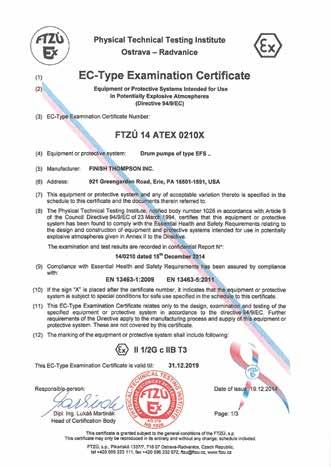
15 EC DECLARATION OF CONFORMITY Finish Thompson Inc. hereby declares that the following machines fully comply with the applicable health and safety requirements as specified by the EC Directives listed. This declaration is valid provided that the devices are fully assembled and no modifications are made to these machines. Type of Device: Drum or Container Pump Pump Models: EFS-16 ATEX, EFS-27 ATEX, EFS-40 ATEX, EFS-48 ATEX EC Directives: Equipment and protective systems intended for use in potentially explosive atmospheres (94/9/EC) EC-Type Examination: Physical Technical testing Institute 1026 Ostrava-Radvanice FTZU 14 ATEX 0210X Product Quality Assurance Notification: Physical Technical Testing Institute 1026 Ostrava-Radanice FTZU 08 ATEX Q 003 Applicable Harmonized Standards: EN : 2011 EN :2009 EN :2011 Casey D. Bowes CEO and President January 6,

16 EC DECLARATION OF CONFORMITY Finish Thompson Inc. hereby declares that the following machines fully comply with the applicable health and safety requirements as specified by the EC Directives listed: Type of Device: Pump Motor Pump Motor Models: S4A EC Directives: Equipment and Protective Systems Intended For Use In Potentially Explosive Atmospheres (94/9/EC) Applicable Harmonized Standards: DIN EN :2011 DIN EN :2099 DIN EN : 2011 The products are marked with the following characteristics: Ex II 2 GD c T4+1 C<Ta<+40 C Documentation archived in FTZÚ Ostrava Radviance, EC code 1026 This declaration is valid provided that the devices are fully assembled and no modifications are made to these machines. CEO and President January 26,
 fully comply with the applicable health and safety requirements as specified be the EC Directives listed.")
17 EU Declaration of Conformity Finish Thompson Inc. hereby declares that the following machine(s) fully comply with the applicable health and safety requirements as specified be the EC Directives listed. The product may not be taken into service until it has been established that the driven Drum and Container pump complies with the provisions of all relevant EC Directives. The complete product complies with the provisions of the EC Directive on machinery safety provided pumps manufactured by Finish Thompson Inc. are used. This declaration is valid provided that the devices are fully assembled and no modifications are made to these devices. Type of Device: Air Motors for Driving Drum and Container Pumps Models: M6 M6X M18 M19 M20 M57 M65 M66 S4 S4A EC Directives: Machinery Safety (2006/42/EC) Applied Harmonized Standards: EN ISO Part 1 EN ISO Part 2 EN 983 Manufacturer: Finish Thompson Inc. 921 Greengarden Road Erie, Pennsylvania U.S.A Signed, President 27 February 2015 Person(s) Authorized to Compile Technical File: Finish Thompson GmbH Otto-Hahn-Strasse 16 Maintal, D DEU Telephone: 49 (0)
18 Service P/N Rev. 0, 3/13/2015
PF SERIES PUMPS PFS OPERATION & PARTS MANUAL
 PF SERIES PUMPS PFS OPERATION & PARTS MANUAL For Serial Number 162859 & above EU Declaration of Conformity Finish Thompson Inc. hereby declares that the following machine(s) fully comply with the applicable
TB SERIES PUMPS TBS OPERATION & PARTS MANUAL
 TB SERIES PUMPS TBS OPERATION & PARTS MANUAL EU Declaration of Conformity Finish Thompson Inc. hereby declares that the following machine(s) fully comply with the applicable health and safety requirements
TBP SERIES PUMPS OPERATION & PARTS MANUAL
 TBP SERIES PUMPS OPERATION & PARTS MANUAL EU Declaration of Conformity Finish Thompson Inc. hereby declares that the following machine(s) fully comply with the applicable health and safety requirements
PF SERIES PUMPS PFS ATEX VERSION (INCLUDES M6A, M6XA, M10X MOTORS & SPK) OPERATION & PARTS MANUAL
 OPERATION & PARTS MANUAL") PF SERIES PUMPS PFS ATEX VERSION (INCLUDES M6A, M6XA, M10X MOTORS & SPK) OPERATION & PARTS MANUAL Introduction This manual pertains to the PF Series, specifically the ATEX version of the PFS stainless
PF SERIES PUMPS PFS ATEX VERSION (INCLUDES M6A, M6XA, M10X MOTORS & SPK) OPERATION & PARTS MANUAL Introduction This manual pertains to the PF Series, specifically the ATEX version of the PFS stainless
EF SERIES PUMPS OPERATION & PARTS MANUAL
 EF SERIES PUMPS OPERATION & PARTS MANUAL EU Declaration of Conformity Finish Thompson Inc. hereby declares that the following machine(s) fully comply with the applicable health and safety requirements
TM SERIES MIXER TMS OPERATION & PARTS MANUAL
 TM SERIES MIXER TMS OPERATION & PARTS MANUAL EU Declaration of Conformity Finish Thompson Inc. hereby declares that the following machine(s) fully comply with the applicable health and safety requirements
EF SERIES MOTORS OPERATION & PARTS MANUAL
 EF SERIES MOTORS OPERATION & PARTS MANUAL Models S1, S2, S3, S4 S1, S2, S3 S4 EU Declaration of Conformity Finish Thompson Inc. hereby declares that the following motors fully comply with the applicable
PF SERIES PUMPS PFM, PFP, PFV OPERATION, INSTALLATION & PARTS MANUAL
 PF SERIES PUMPS PFM, PFP, PFV OPERATION, INSTALLATION & PARTS MANUAL EU Declaration of Conformity Finish Thompson Inc. hereby declares that the following machine(s) fully comply with the applicable health
EF SERIES PUMPS EFP, EFS, & EFV OPERATION & PARTS MANUAL
 EF SERIES PUMPS EFP, EFS, & EFV OPERATION & PARTS MANUAL EU Declaration of Conformity Finish Thompson Inc. hereby declares that the following machine(s) fully comply with the applicable health and safety
PF SERIES PUMPS PFM, PFP, PFV OPERATION, INSTALLATION & PARTS MANUAL
 PF SERIES PUMPS PFM, PFP, PFV OPERATION, INSTALLATION & PARTS MANUAL EU Declaration of Conformity Finish Thompson Inc. hereby declares that the following machine(s) fully comply with the applicable health
MV Series Motors Operation & Parts Manual
 MV Series Motors Operation & Parts Manual Models M3V, M5V, M5V-US For use with M3V s/n 101057 & below, M3V-UK s/n 103013 & below, M5V & M5V-US s/n 102972 & below. EU Declaration of Conformity Finish Thompson
PF SERIES PUMPS PFS ATEX VERSION (INCLUDES M6A, M6XA, M10X MOTORS & SPK) OPERATION & PARTS MANUAL
 OPERATION & PARTS MANUAL") PF SERIES PUMPS PFS ATEX VERSION (INCLUDES M6A, M6XA, M10X MOTORS & SPK) OPERATION & PARTS MANUAL Introduction This manual pertains to the PF Series, specifically the ATEX version of the PFS stainless
PF SERIES PUMPS PFS ATEX VERSION (INCLUDES M6A, M6XA, M10X MOTORS & SPK) OPERATION & PARTS MANUAL Introduction This manual pertains to the PF Series, specifically the ATEX version of the PFS stainless
MV Series Motors Operation & Parts Manual. Models M3V, M5V, M5V-US
 MV Series Motors Operation & Parts Manual Models M3V, M5V, M5V-US Introduction This manual pertains to drum pump motors MV Series. Finish Thompson, Inc. thanks you for choosing our products. We believe
OPERATION AND PARTS MANUAL
 OPERATION AND PARTS MANUAL DRUM PUMPS AND MOTORS HVDP SERIES 1 TABLE OF CONTENTS Introduction...3 Warranty...3 Chemical Reaction Disclaimer...3 Return Policy...3 Safety Precautions...4 Maintenance Precautions...4
S Series Motors. Model S6 * Operation & Parts Manual. For EF Series Pump Tubes Only. Patent pending.
 S Series Motors Model S6 * Operation & Parts Manual For EF Series Pump Tubes Only * Patent pending. EU Declaration of Conformity Finish Thompson Inc. hereby declares that the following electrical equipment
AK / AV 4 & 5 SERIES Metallic Vertical Centrifugal Pumps Installation and Maintenance Instructions
 AK / AV 4 & 5 SERIES Metallic Vertical Centrifugal Pumps Installation and Maintenance Instructions ASSEMBLY PUMPS WITH MOTORS 1. No assembly required. Simply unpack the pump and motor and examine for any
PUMP-FIT MODEL SERIES PF Assembly, Installation and Operation Manual
 PUMP-FIT MODEL SERIES PF66605 Assembly, Installation and Operation Manual EU Declaration of Conformity Pump-Fit hereby declares that the following machine(s) fully comply with the applicable health and
KC 5.5, 6, 6H, 7, 8, & 10 SERIES Non-Metallic Centrifugal Pumps Installation and Maintenance Instructions
 KC 5.5, 6, 6H, 7, 8, & 10 SERIES Non-Metallic Centrifugal Pumps Installation and Maintenance Instructions ASSEMBLY Unpack the pump, drive magnet assembly and hardware package from carton and check for
ALITA LINEAR AIR PUMP OPERATION & MAINTENANCE MANUAL. AL- Model Number Date Code / Serial Number Date of Purchase
 ALITA LINEAR AIR PUMP OPERATION & MAINTENANCE MANUAL AL- Model Number Date Code / Serial Number Date of Purchase LIMITED WARRANTY ALITA warrants to the original retail consumer purchaser ( Customer ) that
User s Guide XXXXXX. Xxxxx Xxxxxxxx. Shop online at. omega.com For latest product manuals: omegamanual.info
 User s Guide Shop online at omega.com e-mail: info@omega.com For latest product manuals: omegamanual.info XXXXXX Xxxxx Xxxxxxxx OMEGAnet Online Service omega.com Internet e-mail info@omega.com Servicing
DB3, 4, 5 & 5.5 Series Sealless Centrifugal Pumps. Assembly, Installation and Operation Manual
 DB3, 4, 5 & 5.5 Series Sealless Centrifugal Pumps Assembly, Installation and Operation Manual EU Declaration of Conformity Finish Thompson Inc. hereby declares that the following machine(s) fully comply
Air Operated Diaphragm Pumps Operating and Maintenance Instructions
 Product & Chemical Disclaimer The user must take responsibility in the selection of the products materials of construction. Empire Pumps Ltd will act in an advisory role and offer recommendations; however,
( Versions Available)
") STYLE 494 ELECTRIC LADDER PIPE INSTALLATION, OPERATING AND MAINTENANCE INSTRUCTIONS ( Versions Available) The following is intended to provide the basic instructions for installation, operating and maintenance
STYLE 494 ELECTRIC LADDER PIPE INSTALLATION, OPERATING AND MAINTENANCE INSTRUCTIONS ( Versions Available) The following is intended to provide the basic instructions for installation, operating and maintenance
Nilfisk-CFM SS Vapor Vacuum Instructions for Use and Spare Parts Manual
 Nilfisk-CFM SS Vapor Vacuum Instructions for Use and Spare Parts Manual Caution: This Nilfisk-CFM vacuum cleaner is not to be used in explosion hazardous areas as serious injury could result. Your new
DeZURIK 2 20" BOS BUTTERFLY VALVES
 2 20" BOS BUTTERFLY VALVES Instruction D10459 October 2013 2-20 BOS Butterfly Valves Instructions These instructions provide information about BOS Butterfly Valves. They are for use by personnel who are
VKC5.5,6,6H, 7,8,10 SERIES
 VKC5.5,6,6H, 7,8,10 SERIES Sealless Non-Metallic Vertical Pumps Installation and Maintenance Instructions Pat.No. 5,708,313 ASSEMBLY WARNING: Magnetic field hazard. This pump contains powerful rare earth
Colt Series C400, C500
 Colt Series C400, C500 RP/IS-A-C400/C500 C400 OSY Reduced Pressure Zone Assemblies Reduced Pressure Detector Assemblies Sizes: 2 1 2" 10" (65 250mm) Installation Service Repair Kits Maintenance For other
LUBRICATOR GUN INSTRUCTIONS-PARTS LIST. 10,000 psi (700 bar) Maximum Delivery Pressure. Detachable-type
 Maximum Delivery Pressure. Detachable-type") INSTRUCTIONS-PARTS LIST 306 460 INSTRUCTIONS This manual contains important warnings and information. READ AND KEEP FOR REFERENCE. Rev. E Supercedes D Detachable-type LUBRICATOR GUN 10,000 psi (700 bar)
INSTRUCTIONS-PARTS LIST 306 460 INSTRUCTIONS This manual contains important warnings and information. READ AND KEEP FOR REFERENCE. Rev. E Supercedes D Detachable-type LUBRICATOR GUN 10,000 psi (700 bar)
MetroPrime 22MPC Self-Priming Centrifugal Pump
 Page 1 of 6 prevent priming or reduce pump capacity. OPERATION The 22 MPC-Metropolitan Pump is a self-priming centrifugal pump and only requires priming prior to its initial start. The pump will retain
Air Operated Double Diaphragm Pump. M-Pump ½ Metallic Non Metallic Pump INSTALLATION, OPERATION & MAINTENANCE MANUAL
 Air Operated Double Diaphragm Pump M-Pump ½ Metallic Non Metallic Pump INSTALLATION, OPERATION & MAINTENANCE MANUAL 0.5 I.O.M rev 05. 12/2015 INDEX Title Section Introduction.1 Safety.2 Warranty, General
Lubricator Gun: 10,000 psi (700 bar) Maximum Delivery Pressure when disconnected from Dispenser
 Maximum Delivery Pressure when disconnected from Dispenser") INSTRUCTIONS-PARTS LIST 30 455 INSTRUCTIONS This manual contains important warnings and information. READ AND KEEP FOR REFERENCE. Rev. C Supercedes B Hand-Operated Portable Grease Dispenser Buckshot Luber
INSTRUCTIONS-PARTS LIST 30 455 INSTRUCTIONS This manual contains important warnings and information. READ AND KEEP FOR REFERENCE. Rev. C Supercedes B Hand-Operated Portable Grease Dispenser Buckshot Luber
18VDC ESB6-X Series Cordless Screwdrivers Operation Manual
 18VDC ESB6-X Series Cordless Screwdrivers Screwdriver Models : ESB6-X3.5, ESB6-X3.5F, ESB6-X5F ESB6-X6, ESB6-X9, ESB6-X12 CAUTION - Please read, understand, and follow all operating and safety instructions
Models: 8500, 8501, 8513, 8514, 8500BL, 8501BL, 8513BL, 8514BL, 8540, 8541, 8550, 8551, 8540BL, 8541BL, 8550BL & 8551BL
 Standard Pump Ultra Mass High Viscosity Batch Control System Description Standard s Drum Pumps are designed to transfer a variety of materials from 55 gallon drums and tanks. Standard Pump offers several
Centrifugal Drum Pump Motor Models: SP-410EX, SP-420EX, SP-280P, SP-ENC, SP-A1 & SP-A2
 Standard Pump Standard s Drum Pumps are designed to transfer a variety of materials from 55 gallon drums and tanks. Standard Pump offers several different pumps, each designed for specific applications.
SERIES FE MAGNETIC COUPLED PUMPS
 SERIES FE MAGNETIC COUPLED PUMPS Refer to Bulletin P-518 O-2804 TABLE OF CONTENTS Description Page Number Important Information...3 Chemical Reaction Disclaimer...3 Safety Precautions...3 Installation/Operation
Sample Pro 3/4" Portable MicroPurge Pump. User's Guide P/N REV The World Leader in Air Powered Pumps
 PATENT PENDING Pro 3/4" Portable MicroPurge Pump User's Guide P/N 959 REV. -8-03 The World Leader in Air Powered For Remediation, Landfills and Ground Water Sampling Ground water Sampling Remediation,
VKC5.5,6,6H, 7,8,10 SERIES Sealless Non-Metallic Vertical Pumps Installation and Maintenance Instructions. Pat.No. 5,708,313
 ASSEMBLY WARNING: Magnetic field hazard. This pump contains powerful rare earth magnets. When the pump is disassembled (not connected to a motor) and the magnets are exposed, these magnets produce powerful
18VDC ESB6 Series Cordless Screwdrivers Operation Manual
 18VDC ESB6 Series Cordless Screwdrivers Screwdriver Models : ESB6-8, ESB6-12, ESB6-15, ESB6-22 CAUTION - Please read, understand, and follow all operating and safety instructions in this manual before
Operation Manual FLG-G5 Transtech Gravity Spray Gun SB-E ISS.05
 Operation Manual FLG-G5 Transtech Gravity Spray Gun SB-E-2-790 ISS.05 Operation Manual FLG5 Gravity-feed Spray Gun Important Read and follow all instructions and Safety Precautions before using this equipment
Models: 8500, 8501, 8513, 8514, 8500BL, 8501BL, 8513BL, 8514BL, 8540, 8541, 8550, 8551, 8540BL, 8541BL, 8550BL & 8551BL
 Standard Pump Ultra Mass High Viscosity Batch Control System Description Standard s Drum Pumps are designed to transfer a variety of materials from 55 gallon drums and tanks. Standard Pump offers several
CRD610 Automatic Fitting Inserter
 CRD610 Automatic Fitting Inserter OPERATIONS MANUAL VERSION 1.2 LAST EDITED 12.12.2018 cleanroomdevices.com 1 Table of Contents Title Page. 1 Table of Contents...2 1.0 General Product & Safety Information....3
Model FM1000 Series Operating Instructions. Drum Pump Flow Meter
 Model FM1000 Series Operating Instructions Drum Pump Flow Meter Table of Contents Safety... 1 Introduction... 1 Specificatons... 1 Features... 1 Section 1 - Installation... 2 Section 2 - Operation... 2
OWNER/OPERATOR MANUAL. Airmotor effective dia. in. 2.5
 MODELS 282050, 282716 & 283513 AIR OPERATED CHASSIS PUMP SERIES A OWNER/OPERATOR MANUAL SPECIFICATIONS Airmotor effective dia. in. 2.5 Airinlet Material outlet 1/4 NPTF 1/4 NPTF Liquid to Air Pressure
Series 957, 957N, 957Z, 957RPDA, 957NRPDA, 957ZRPDA
 Series 957, 957N, 957Z, 957RPDA, 957NRPDA, 957ZRPDA Reduced Pressure Zone Assemblies Reduced Pressure Detector Assemblies Sizes: 2 1 2" 10" (65 250mm) Installation Service Repair Kits Maintenance RP/IS-957/957RPDA
Straight-Bore Clutch LSCC-32, 44, 54
 Straight-Bore Clutch LSCC-32, 44, 54 1 In accordance with Nexen s established policy of constant product improvement, the specifications contained in this manual are subject to change without notice. Technical
Hydraulic Transmission Jacks
 Hydraulic Transmission Jacks Operating Instructions & Parts Manual Model Number Atd-7435 Atd-7436 Atd-7437 Capacity 1100 Lb. 2000 Lb. 3000 Lb. Model Atd-7435 Model Atd-7436 Model Atd-7437 Atd Tools Inc.
POLYPROPYLENE PUMP TUBE SP-PP SERIES
 POLYPROPYLENE PUMP TUBE SP-PP SERIES * * * 0 * V-seal - Viton Pump coupling Drive shaft, " (00 mm) Discharge housing Bearing unit assembled - each Viton shielded bearings, spacer, snap ring, bearing can
USER MANUAL. NEMA 48C Flange Mounted, Enclosed, Clutch Brake. FMCBE Model 500 FORM NO. L A (i)
") USER MANUAL NEMA 48C Flange Mounted, Enclosed, Clutch Brake FMCBE Model 500 (i) In accordance with Nexen s established policy of constant product improvement, the specifications contained in this manual
USER MANUAL NEMA 48C Flange Mounted, Enclosed, Clutch Brake FMCBE Model 500 (i) In accordance with Nexen s established policy of constant product improvement, the specifications contained in this manual
Operator s Manual. Nitro 1000 Nitro 1000X. Nitro 750 Nitro 750X. September REV0
 Operator s Manual Nitro 750 Nitro 750X Nitro 1000 Nitro 1000X September.27.2018REV0 Table of Contents Introduction...3 Safety.....4 Equipment Requirements......5 What You Have Received. 5 Serial Number...6
4. All Federal, State, and local safety codes should be followed.
 Standard Pump Description Standard s Drum Pumps are designed to transfer a variety of materials from 55 gallon drums and tanks. Standard Pump offers several different pumps, each designed for specific
OWNER S MANUAL EVOLUTION 3500, 4500, 5500, & 8500 SERIES PUMPS
 OWNER S MANUAL EVOLUTION 3500, 4500, 5500, & 8500 SERIES PUMPS IMPORTANT SAFETY INSTRUCTIONS When installing and using this electrical equipment, basic safety precautions should always be followed, including
Linear Actuator. Installation Manual. warranty installation parts list. Linear Actuator Installation Manual Page 1
 Linear Actuator Installation Manual warranty installation parts list January 2004 Linear Actuator Installation Manual Page 1 MA1221B12 Warranty Information Chore-Time Equipment ( Chore-Time ) warrants
GEN-3 Super-duty Supercharger Shaft Kit PART# - RY17040-UK-6S5-3
 GEN-3 Super-duty Supercharger Shaft Kit PART# - RY17040-UK-6S5-3 We strongly recommend the use of a service manual to familiarize yourself with the various components and procedures involved with this
CRD600 Automatic Fitting Inserter
 CRD600 Automatic Fitting Inserter OPERATIONS MANUAL VERSION 2.3 LAST EDITED 12.07.2018 cleanroomdevices.com 1 Table of Contents Title Page.. 1 Table of Contents. 2 1.0 General Product & Safety Information...3
4000SS. For other repair kits and service parts, send for Ames Repair Parts Price List, PL-A-RP-BPD.
 Series 4000SS RP/IS-A-4000SS 4000SS Reduced Pressure Zone Assemblies Sizes: 8" 10" (200 250mm) Installation Service Repair Kits Maintenance For other repair kits and service parts, send for Ames Repair
APCO CRF-100A RUBBER FLAPPER SWING CHECK VALVES
 APCO CRF-100A RUBBER FLAPPER SWING CHECK VALVES Instruction D12043 June 2016 DeZURIK Instructions These instructions provide installation, operation and maintenance information for APCO CRF-100A Rubber
1. Before operating the pump, read and understand these operating instructions.
 Standard Pump Description Standard s Drum Pumps are designed to transfer a variety of materials from 55 gallon drums and tanks. Standard Pump offers several different pumps, each designed for specific
TBM Series 3-Way Ball Valve
 www.simtechusa.com TBM Series 3-Way Ball Valve Operating, Installation, & Maintenance Manual Corrosion Resistant Fluid and Air Handling Systems. Dated 06-26-13 TBM Series Ball Valves SIMTECHRECOMMENDSREADINGTHEFOLLOWINGINFORMATIONPRIORTOINSTALLINGANDUSING
HSIV PLOW OPERATOR S MANUAL
 PLOW RWF INDUSTRIES 873 Devonshire Ave., Woodstock, Ontario N4S 8Z4 Tel: (519) 421-0036 Toll Free: 1-800-263-1060 Fax: (519) 421-0028 Email: parts@rwfbron.com JANUARY 2015 THE INFORMATION CONTAINED IN
Heavy Duty Engine Cranes
 Heavy Duty Engine Cranes Operating Instructions & Parts Manual Model Number Atd-7484 Atd-7485 (Foldable Legs) Capacity 2 Ton 2 Ton Model Atd-7484 Model Atd-7485 Atd Tools Inc. 160 Enterprise Drive, Wentzville,
BMRX Series ROTARY LEVEL CONTROL
 BMRX Series ROTARY LEVEL CONTROL OPERATING INSTRUCTIONS PLEASE READ CAREFULLY 925-0292 Rev C TABLE OF CONTENTS GENERAL SPECIFICATIONS... 3 SAFETY SUMMARY... 4 1.0 INTRODUCTION... 5 2.0 INSTALLATION...
CONTENTS. VIKING PUMP, INC. A Unit of IDEX Corporation Cedar Falls, IA USA SECTION TSM 710.1
 TECHNICAL SERVICE MANUAL industrial heavy duty motor speed pumps SERIES 4076 AND 4176 SIZES hle, ate and ale SECTION TSM 710.1 PAGE 1 of 8 ISSUE B CONTENTS Introduction....................... 1 Safety
CRD400 Fitting Inserter OPERATIONS MANUAL
 CRD400 Fitting Inserter OPERATIONS MANUAL ORIGINAL INSTRUCTIONS VERSION 3.4 LAST EDITED 01.07.2019 www.cleanroomdevices.com 1 Table of Contents Title Page.. 1 Table of Contents... 2 1.0 General Product
Operation Manual Cobra 1 Automatic Spray Gun
 SB-E-2-CBA1 ISS.06 Operation Manual Cobra 1 Automatic Spray Gun E P 1 12 1 Operation Manual Cobra 1 Automatic Spraygun Important Read and follow all instructions and Safety Precautions before using this
CLEAN ROOM DEVICES, LLC "WHERE TUBING AND FITTINGS COME TOGETHER"
 CLEAN ROOM DEVICES, LLC "WHERE TUBING AND FITTINGS COME TOGETHER" CRD600AF Automatic Fitting Inserter With Auto Feed OPERATIONS MANUAL (Shown with optional alcohol dispenser) 1 VERSION 1.1 LAST EDITED
AGITATED LID ASSEMBLY
 SERVICE MANUAL EN 31-425 AGITATED LID ASSEMBLY 41-3312, 41-3312-S DIRECT DRIVE AGITATORS 77-1474-R20 (3/2018) 1 / 8 www.carlisleft.com AGITATOR ASSEMBLY FOR 25 Litre (5 Gal.) PAIL IMPORTANT: Read and follow
PREDICTIVE STEERING HUBS. Service Manual
 2015 PREDICTIVE STEERING HUBS Service Manual SRAM LLC WARRANTY EXTENT OF LIMITED WARRANTY Except as otherwise set forth herein, SRAM warrants its products to be free from defects in materials or workmanship
HALLMARK INDUSTRIES INC
 Performance Part No. HP. CONVERTIBLE JET PUMP USER S MANUAL GPH of Water @ Total Discharge Pressure of 40 psi Max. Pressure Max suction (shallow well) Max Suction (deep well) Max GPM (@0 head) Max Discharge
Elgin Hydraulic Clutch-Brake ECB-240, Product Number FORM NO. L F FORM NO. L F-0704
 Elgin Hydraulic Clutch-Brake ECB-20, Product Number 96225 FORM NO. L-20283-F-070 1 FORM NO. L-20283-F-070 In accordance with Nexen s established policy of constant product improvement, the specifications
580RK SERVICE GUIDELINES For coupling models: 580 & 580J
 580 Coupling THE FIRST NAME IN QUALITY COUPLINGS 580RK SERVICE GUIDELINES For coupling models: 580 & 580J BEFORE GETTING STARTED: This procedure should only be performed by a qualified mechanic. Measure
SB-E-2-CBA1 ISS.13. Operation Manual Cobra 1 Automatic Spray Gun
 EN SB-E-2-CBA1 ISS.13 Operation Manual Cobra 1 Automatic Spray Gun Operation Manual Cobra 1 Automatic Spraygun Important Read and follow all instructions and Safety Precautions before using this equipment
Air Actuated Hydraulic Bottle Jack on Wheels
 Operating Instructions & Parts Manual Air Actuated Hydraulic Bottle Jack on Wheels Model Number 18127 18207 Capacity 12 Ton 20 Ton Shinn Fu Co. of America, Inc. 2002 10939 N. Pomona Avenue Kansas City,
DAP-625S and DAP-875S
 AIR CHAMP PRODUCTS DAP-625S and DAP-875S (i) FORM NO. L-20078-B-0501 In accordance with Nexen s established policy of constant product improvement, the specifications contained in this manual are subject
BC Brake Caliper. (i) MEX (55) QRO (442) MTY (81) DIST. AUTORIZADO
 MEX (55) QRO (442) MTY (81) DIST. AUTORIZADO") MEX (55) 5 6 QRO (44) 95 7 60 MTY () 54 0 BC Brake Caliper (i) FORM NO. L-0066-B-040 In accordance with Nexen s established policy of constant product improvement, the specifications contained in this
MEX (55) 5 6 QRO (44) 95 7 60 MTY () 54 0 BC Brake Caliper (i) FORM NO. L-0066-B-040 In accordance with Nexen s established policy of constant product improvement, the specifications contained in this
operating instruction
 operating instruction a.560pn #125101 DE, EN, FR, SE Table of Contents Installation... 3 Tool use...4-5 Safety precautions...6-7 Troubleshooting and maintenance... 8 Technical specification... 9 Spare
Operation & Technical Manual. Model: Ground Test Motor
 Operation & Technical Manual Model: 13-6604-6600 Ground Test Motor 05/2009 Rev. 05 Includes Illustrated Parts Lists DEVELOPED IN CONJUNCTION WITH HAMILTON-SUNDSTRAND 1740 Eber Rd Tronair, Inc. Phone: (419)
OWNER S MANUAL SELF-PRIMING PORTABLE UTILITY PUMP
 Model 54011-0 OWNER S MANUAL SELF-PRIMING PORTABLE UTILITY PUMP Questions, problems, missing parts? Before returning to the store call AQUAPRO Customer Service 8 a.m. - 5 p.m., EST, Monday-Friday 1-844-242-2475
PARTS AND INSTALLATION MANUAL
 PSP-3240 POLYPROPYLENE SELF-PRIMING 2 CENTRIFUGAL PUMP PARTS AND INSTALLATION MANUAL PSP-3240 Shown with GX-160 Honda CDS-JOHN BLUE COMPANY DIVISION OF ADVANCED SYSTEMS TECHNOLOGY, INC. 165 Electronics
Installation, Operation, and Maintenance Manual
 Industrial Process Installation, Operation, and Maintenance Manual Cam-Tite Ball Valve Table of Contents Table of Contents Introduction and Safety...2 Safety message levels...2 User health and safety...2
Instruction Manual For Baldor Buffers
 No. 280F Replaces 280E LB7011 Instruction Manual For Baldor Buffers SAFETY NOTICE: WARNING statements describe conditions that may lead to personnel injury including potentially fatal injuries if the machine
PENBERTHY MODELS GL AND GH GAS OPERATED JET PUMPS INSTALLATION, OPERATION AND MAINTENANCE INSTRUCTIONS
 Before installation, these instructions must be read carefully and understood. PRODUCT WARRANTY Emerson warrants its Penberthy products as designed and manufactured to be free of defects in the material
Manifold w/ Needle Valve Instruction Manual
 MODELS: MFC2 & MFC4 Manifold w/ Needle Valve Instruction Manual SFA Companies 10939 N. Pomona Ave. Kansas City, MO 64153 Tel: 888-332-6419 - Fax: 816-448-2142 E-mail: sales@bvahydraulics.com Website: www.bvahydraulics.com
900 SERIES SPLIT CASE FIRE PUMP REPAIR PARTS INDEX
 900 SERIES SPLIT CASE FIRE PUMP REPAIR PARTS INDEX Read and understand the pump and motor instructions before attempting to install, disassemble or repair the pump. Part # AF-03-326 2015 Pentair Ltd. 01/30/15
UV PROCESS SUPPLY, INC.
 UV PROCESS SUPPLY, INC. GENERAL DESCRIPTION The ¼ Diaphragm Pump others high volume delivery even at low air pressures, easy self-priming, the ability to pump various viscosity materials and the ability
CLEAN ROOM DEVICES, LLC "WHERE TUBING AND FITTINGS COME TOGETHER"
 CLEAN ROOM DEVICES, LLC "WHERE TUBING AND FITTINGS COME TOGETHER" CRD600 Automatic Fitting Inserter OPERATIONS MANUAL VERSION 2.1 LAST EDITED 7.25.14 DOCUMENT NUMBER 001 cleanroomdevices.com 1 Table of
AXIAL FANS Axis / Tubo OPERATION MANUAL
 TUBO-M AXIS-QA AXIS-Q AXIS-QR AXIS-F AXIS-QRA AXIAL FANS Axis / Tubo OPERATION MANUAL Axis / Tubo www.blaubergventilatoren.de CONTENT 3 Introduction 3 General 3 Safety rules 3 Transport and storage requirements
Guardian Steel Gear Shaft Coupling
 Guardian Steel Gear Shaft Coupling P-8609-GC GUA-MRK-DOC-026 Service & Installation Instructions TABLE OF CONTENTS NOTICES AND WARNINGS PAGE 2 SECTION 1 COUPLING OVERVIEW PAGE 3 SECTION 2 TOOLS/MATERIALS
NOTE: Visit our website at for video repair procedures, under the Tools section.
 Repair Instructions Hypro Repair Tools: Tool Box No. 3010-0168 1/4" Allen Wrench No. 3020-0008 Support Bars (2) No. 3010-0064 Port Brush No. 3010-0066 1/16" Allen Wrench No. 3020-0009 Brush Holder No.
Model FMBC3000 Series Operating Instructions. Drum Pump Flow Meter
 Model FMBC3000 Series Operating Instructions Drum Pump Flow Meter Table of Contents Safety... 1 Introduction... 1 Specificatons... 1 Features... 1 Section 1 - Installation... 2 Section 2 - Operation...
Guardian Taper Grid Shaft Coupling
 Guardian Taper Grid Shaft Coupling P-8608-GC GUA-MRK-DOC-025 Service & Installation Instructions TABLE OF CONTENTS NOTICES AND WARNINGS PAGE 2 SECTION 1 COUPLING OVERVIEW PAGE 3 SECTION 2 TOOLS/MATERIALS
INSTALLATION NOTES: nbeckon-26
 INSTALLATION NOTES: nbeckon-26 1. Caution and Safety Instructions Qualified personnel must install and/or service product in a manner consistent with its intended use and in compliance with the National
Installation and Maintenance Manual
 Installation and Maintenance Manual WorldWide Helical Inline Speed Reducers This operation manual includes important information for the installation, assembly, operation and maintenance of the WorldWide
Heavy Duty Engine Cranes
 Heavy Duty Engine Cranes Operating Instructions & Parts Manual Model Number ATD-7484 ATD-7485 (Foldable Legs) Capacity 2 Ton 2 Ton Model ATD-7484 Model ATD-7485 WARNING: This product may contain chemicals,
INSTALLATION INSTRUCTION & OWNER S MANUAL
 CS-2500 & CS-2500P Water Filtration System INSTALLATION INSTRUCTION & OWNER S MANUAL Ver 1.2 All Rights Reserved APEC Water Systems Please keep this Owner s Manual for future reference. It contains useful
Service Letter. Ariens Company 655 W. Ryan St. Brillion, WI
 Date: Dec. 2012 No. L-2124R Service Letter Ariens Company 655 W. Ryan St. Brillion, WI 54110 www.ariens.com Product Family: Ariens and Gravely Products with Hydro-Gear Components Subject: Hydro-Gear Warranty
FCB-450, LCB-600, MCB-800
 AIR CHAMP PRODUCTS User Manual FCB-450, LCB-600, MCB-800 Clutch-Brakes (i) In accordance with Nexen s established policy of constant product improvement, the specifications contained in this manual are
Operating Instructions
 Operating Instructions WARNING: Do not attempt to assemble, connect to power source, or operate the Burrell Wrist-Action Shaker without first reading these instructions. Also assure that each person that
MODEL 1385 & 1385-H Professional Rotary Drum Pump
 NOV - 2010 Form 404168 Section - B5 Page - 47 OWNER/OPERATOR RESPONSIBILITY All instructions and warnings contained in this manual shall be read and understood by the owner/operator prior to operating
EZ-IN Series Turbine Flowmeter
 Class I, Group A, B, C, D, Division I Complies with ASME Standard B31.3 NUFLO EZ-IN Series Turbine Flowmeter Installation Manual Part No. 9A-100062997, Rev. 01 Measurement Systems EZ-IN Series BF Turbine
TECHNICAL SERVICE MANUAL
 Electronic copies of the most current TSM issue can be found on the Viking Pump website at www.vikingpump.com TECHNICAL SERVICE MANUAL industrial heavy duty motor speed pumps SERIES 4076 AND 4176 SIZES